JP2012024965A - Paper container forming machine - Google Patents

Paper container forming machine Download PDF

Info

Publication number
JP2012024965A
JP2012024965A JP2010163764A JP2010163764A JP2012024965A JP 2012024965 A JP2012024965 A JP 2012024965A JP 2010163764 A JP2010163764 A JP 2010163764A JP 2010163764 A JP2010163764 A JP 2010163764A JP 2012024965 A JP2012024965 A JP 2012024965A
Authority
JP
Japan
Prior art keywords
blank
hot air
mandrel
heat
paper
Prior art date
Legal status (The legal status is an assumption and is not a legal conclusion. Google has not performed a legal analysis and makes no representation as to the accuracy of the status listed.)
Granted
Application number
JP2010163764A
Other languages
Japanese (ja)
Other versions
JP5587077B2 (en
Inventor
Shigeru Kuriyama
茂 栗山
Takehiro Matsumoto
武浩 松本
Motoyoshi Murata
元義 村田
Current Assignee (The listed assignees may be inaccurate. Google has not performed a legal analysis and makes no representation or warranty as to the accuracy of the list.)
Daiwa Can Co Ltd
Shin Nippon Koki KK
Dixie Japan Ltd
Original Assignee
Daiwa Can Co Ltd
Shin Nippon Koki KK
Dixie Japan Ltd
Priority date (The priority date is an assumption and is not a legal conclusion. Google has not performed a legal analysis and makes no representation as to the accuracy of the date listed.)
Filing date
Publication date
Application filed by Daiwa Can Co Ltd, Shin Nippon Koki KK, Dixie Japan Ltd filed Critical Daiwa Can Co Ltd
Priority to JP2010163764A priority Critical patent/JP5587077B2/en
Publication of JP2012024965A publication Critical patent/JP2012024965A/en
Application granted granted Critical
Publication of JP5587077B2 publication Critical patent/JP5587077B2/en
Active legal-status Critical Current
Anticipated expiration legal-status Critical

Links

Images

Abstract

PROBLEM TO BE SOLVED: To surely prevent all areas except a target area from being heated, when the restricted range of the end of a blank where a thermoplastic resin is provided on the front or rear surface thereof is heated to melt or soften the thermoplastic resin.SOLUTION: A heating device in a paper container forming machine includes a heater 27 ejecting hot air toward the front surface of one end of the blank 5 or the rear surface of the other end of the blank 5 and a heat insulation member which is closely adhered to the front surface or the rear surface, exposes the area where a synthetic resin is softened or melted of the front surface or the rear surface to the hot air and shields all places except the area of the front surface or the rear surface from the hot air.

Description

本発明は、板紙基材に例えばポリエチレン樹脂がラミネートされたブランクシートより形成された切頭円錐状(以下、「テーパー形状」とも呼ぶ)のシェルやそのシェルの底部に板紙製の底板を取り付けたテーパー形状の容器などを成形するための装置に関し、特にその製造過程でラミネート樹脂を溶融させて板紙基材の端部同士を接着するために、その板紙基材の両端部を加熱して、その表面の合成樹脂を溶融もしくは軟化させる加熱装置を備えた成形機に関するものである。   In the present invention, a frustoconical (hereinafter also referred to as “taper shape”) shell formed from a blank sheet in which, for example, a polyethylene resin is laminated on a paperboard substrate, and a bottom made of paperboard are attached to the bottom of the shell. With regard to an apparatus for molding a tapered container or the like, in particular, in order to melt the laminating resin and bond the ends of the paperboard substrate in the production process, both ends of the paperboard substrate are heated, The present invention relates to a molding machine provided with a heating device for melting or softening a synthetic resin on the surface.

従来、インスタント食品やスナック菓子などの食品用の容器として、コップや椀などのガラス製あるいは陶器製の容器を模して樹脂により作成された容器が使用されていることは周知のとおりである。これらの容器は樹脂製であることにより成形性が良好で、形状の自由度が高いが、最近では環境に対する負荷の低減や加工技術の向上によって、従来樹脂製とされていた容器を紙製とすることが試みられるようになってきている。   As is well known, as a container for foods such as instant foods and snacks, a container made of a resin simulating a glass or earthenware container such as a cup or candy is used. These containers are made of resin and have good moldability and a high degree of freedom in shape.Recently, containers made of resin have been replaced with paper by reducing the burden on the environment and improving processing technology. Attempts have been made to do so.

このような容器に用いられる紙基材として、容器の耐水性を確保し、また断熱性を高めるために、合成樹脂をコーティングもしくはラミネートされたものが使用される。そのため、ブランクシートからカップ胴部用のブランクを打ち抜き、筒状に成形するために、ブランクを丸めるのに先立って、ブランクの一方の端部表面と他方の端部裏面とのそれぞれを加熱することにより、それらの接着対象部分の合成樹脂を溶融もしくは軟化させ、ブランクを切頭円錐状に丸めた際にそれらの部分を互いに重ね合わせて加圧し、合成樹脂を接着剤として、ブランクの端部同士を接合している。これによりカップ容器における胴部が成形され、この胴部に対してボトム部(底部)が取り付けられ、また、端部がカール成形され、紙製の容器が製造される。胴部を構成するブランクの端部同士を接合するための合成樹脂などの溶融もしくは軟化は、加熱装置によるホットエア(以下、「熱風」ともいう)などで行われ、このような紙製の容器の成形工程におけるブランクの加熱方法および装置が特許文献1ないし4に記載されている。   As a paper base material used for such a container, a synthetic resin-coated or laminated one is used in order to ensure the water resistance of the container and to improve the heat insulation. Therefore, in order to punch out the blank for the cup body from the blank sheet and form it into a cylindrical shape, heating each of the one end surface and the other end back surface of the blank prior to rounding the blank. By melting or softening the synthetic resin of the parts to be bonded, when the blanks are rounded into a truncated cone, the parts are overlapped and pressed together, and the ends of the blanks are bonded together using the synthetic resin as an adhesive. Are joined. Thereby, the trunk | drum in a cup container is shape | molded, a bottom part (bottom part) is attached with respect to this trunk | drum, and an edge part is curled, and a paper container is manufactured. The melting or softening of the synthetic resin or the like for joining the end portions of the blank constituting the body portion is performed by hot air (hereinafter, also referred to as “hot air”) by a heating device, and such a paper container Patent Documents 1 to 4 describe a blank heating method and apparatus in a molding process.

特許文献1には、両端部から成る一対ののりしろ部を互いに結合することによりほぼテーパー形状の筒紙となるように、多少湾曲した長方形状のシート部材から構成され、紙をベースとしてその表面を熱可塑性樹脂で被覆されているブランクにより筒状体すなわち紙コップを成形する筒状体成形装置が記載されている。この筒状体成形装置には、シート状ブランクをマンドレルに供給するためのコンベア機構およびブランク位置決め台が設けられている。コンベア機構は、上下一対のベルトコンベアから成り、これら一対のベルトコンベアの間に挟持されたブランクをターレットの中心に向かう方向に移送してブランク位置決め台に順次供給する。ブランクは、この供給の途中において、コンベア機構の左右両側に配置された左右一対のガスバーナなどの加熱手段によりその左右両端部が加熱されて、その表面の熱可塑性樹脂が溶融される。そして、ブランクは、マンドレルの外周面にほぼ切頭円錐状となるように巻き付けられて、その左右両端部から成る一対ののりしろ部が互いに重ね合せられてのりしろ部が互いに溶着されるので、ほぼテーパー形状の筒紙となる。その後、底紙ののりしろ部が筒紙の底部とこの筒紙の上記底部に隣接する部分との間に挟み込まれる。また、この挟み込みにより、のりしろ部は、上記底部と上記隣接部分とにそれぞれ溶着され、カーリングなどが施されて、紙コップの完成品に仕上げられる。   In Patent Document 1, a pair of marginal portions composed of both end portions are combined with each other so as to form a substantially tapered tubular paper sheet, which is composed of a slightly curved rectangular sheet member. A cylindrical body forming apparatus for forming a cylindrical body, that is, a paper cup, with a blank coated with a thermoplastic resin is described. The cylindrical body forming apparatus is provided with a conveyor mechanism and a blank positioning table for supplying a sheet blank to a mandrel. The conveyor mechanism is composed of a pair of upper and lower belt conveyors, and a blank held between the pair of belt conveyors is transferred in a direction toward the center of the turret and sequentially supplied to the blank positioning table. In the middle of this supply, the blank is heated at both left and right ends by a heating means such as a pair of left and right gas burners arranged on the left and right sides of the conveyor mechanism, and the thermoplastic resin on the surface is melted. The blank is wound around the outer peripheral surface of the mandrel so as to have a substantially truncated conical shape, and a pair of margins composed of left and right ends thereof are overlapped with each other, and the margins are welded to each other. It becomes a tube paper of shape. Thereafter, the margin of the bottom paper is sandwiched between the bottom of the tube paper and the portion adjacent to the bottom of the tube paper. Further, by this sandwiching, the margin part is welded to the bottom part and the adjacent part, respectively, and is subjected to curling or the like to finish a finished paper cup.

特許文献2には、コップ状耐熱紙容器の製造ラインが高速であっても、コップ状耐熱紙容器の胴部のサイドシール部を、接着剤を使用せずにヒートシールのみで確実に接着でき、内容物が液体であっても液漏れが発生することなく、オーブンや電子レンジで加熱することができるコップ状耐熱紙容器及びその製造方法が記載されている。より具体的には、胴部のサイドシール部では、胴部用ブランクの縦方向端縁のポリエステル系樹脂フィルム層をホットエアで急速加熱して溶融させ、溶融したポリエステル系樹脂フィルム層と他方の端縁外層とが圧着されて、コップ状耐熱紙容器が形成される。   In Patent Document 2, even if the production line of a cup-shaped heat-resistant paper container is high-speed, the side seal portion of the body of the cup-shaped heat-resistant paper container can be securely bonded only by heat sealing without using an adhesive. A cup-shaped heat-resistant paper container that can be heated in an oven or a microwave oven without causing liquid leakage even if the contents are liquid and a method for manufacturing the same are described. More specifically, in the side seal portion of the body portion, the polyester resin film layer at the longitudinal direction edge of the body portion blank is rapidly heated and melted with hot air, and the molten polyester resin film layer and the other end are melted. The outer edge layer is pressure-bonded to form a cup-shaped heat-resistant paper container.

特許文献3には、サイドブランクの接着対象部位にホットエアを吹き付けるプレヒーター機構が記載されている。このプレヒーター機構は、カップ成型装置及びブランク供給部とともに備えられ、ヒーター本体と、ホットエアを排出するヒーター本体の排出口に連通するとともにサイドブランク側に向かって開口する第1凹部を有するベース部と、前記第1凹部と相まってホットエアの通路を形成する第2凹部と、接着対象部位に沿うように配置されて第2凹部とサイドブランク側の外部とを連通するノズル孔とを有するノズル部と、通路に沿って形成され通路内を少なくとも2つの部位に仕切るとともに、仕切られた通路の一方側の部位から他方側の部位への前記ホットエアの流通を可能とする切欠部を有する仕切プレートとを備えている。そして、プレヒーター機構の通路に仕切プレートを設け、この切欠部の大きさや形成位置を部分的に調節することにより、ホットエアの量を部分的に増減し、加熱処理の性能を向上させ、所望の接着強度を確保できるようにしたことが記載されている。   Patent Document 3 describes a pre-heater mechanism that blows hot air onto a bonding target portion of a side blank. The pre-heater mechanism is provided with a cup molding device and a blank supply unit, and has a heater body, a base portion having a first recess that communicates with a discharge port of the heater body that discharges hot air and opens toward the side blank side. A nozzle portion having a second recess that forms a passage of hot air in combination with the first recess, and a nozzle hole that is disposed along the bonding target portion and communicates with the second recess and the outside on the side blank side; A partition plate that is formed along the passage and divides the passage into at least two portions, and has a notch portion that allows the hot air to flow from one portion of the partitioned passage to the other portion. ing. A partition plate is provided in the passage of the pre-heater mechanism, and by partially adjusting the size and position of the notch, the amount of hot air is partially increased or decreased to improve the performance of the heat treatment. It describes that the adhesive strength can be secured.

特許文献4に記載された容器成型装置には、シート材からなるサイドブランクの一方の主面の加熱対象部位にホットエアを吹き付けて加熱するプレヒーター機構と、サイドブランクの他方の主面側を支持する板状の支持機構とを備え、支持機構はその内部に冷却水が流通する通路が形成され、通路は、加熱対象部位から離れて配置されているブランク処理装置が記載され、ブランクに加熱処理等の処理を施す際に、ホットエアの吹き付けによりサイドブランクが変形するのを防ぎ、また、加熱対象部位以外の部分が必要以上に加熱されるのを防ぐことができると記載されている。   The container molding apparatus described in Patent Document 4 supports a pre-heater mechanism that heats hot air by spraying a portion to be heated on one main surface of a side blank made of a sheet material, and the other main surface side of the side blank. A plate-like support mechanism is formed, a passage through which the cooling water flows is formed in the support mechanism, and the passage describes a blank processing device arranged away from the heating target part, and the blank is heat-treated. It is described that the side blank can be prevented from being deformed by blowing hot air and other parts than the part to be heated can be prevented from being heated more than necessary.

特許第3513717号公報Japanese Patent No. 3513317 特開2003−200920号公報JP 2003-200920 A 特開2009−83237号公報JP 2009-83237 A 特開2009−83238号公報JP 2009-83238 A

上述した特許文献1に記載の筒状体成形装置は、コンベア機構の左右両側に配置された左右一対のガスバーナなどの加熱手段によりその左右両端部が加熱されて、シート状ブランクの表面の熱可塑性樹脂が溶融される構成となっている。このようなガスバーナの火炎は、ブランクの端部を直接加熱するだけでなく、周囲の空気を加熱し、またその加熱した空気を火炎と共にブランクの端部に吹き付けるように作用するから、ブランクの広い範囲が加熱される可能性が高い。そのため、互いに接合するべき端部に隣接する部分をも加熱されて表面の合成樹脂が溶融もしくは軟化してしまい、さらには不必要に発泡してしまう虞がある。   In the cylindrical body forming apparatus described in Patent Document 1 described above, the left and right ends are heated by heating means such as a pair of left and right gas burners arranged on the left and right sides of the conveyor mechanism, and the thermoplasticity of the surface of the sheet-like blank is obtained. The resin is melted. Such a gas burner flame not only directly heats the edge of the blank, but also heats the surrounding air and blows the heated air along with the flame onto the edge of the blank, so that the blank of the blank The range is likely to be heated. For this reason, the portions adjacent to the end portions to be joined to each other are also heated, so that the synthetic resin on the surface may be melted or softened and further foamed unnecessarily.

また、特許文献2の発明では、加熱のためにホットエアをカーテン状に噴射しているが、コップ状耐熱紙容器のサイドシール部に吹き付けられたホットエアは、未だ熱を持ったままその周囲に拡がるから、加熱箇所を決められた局部に限ることが困難であり、上記の特許文献1に記載されている発明と同様に、ブランクの端部に隣接する部分をも加熱してしまって、加熱対象部位以外の部分における合成樹脂が必要以上に加熱されて溶融や軟化、あるいは発泡を招来し、その後のブランクフィードへの悪影響やシェルフォーミングの成形不良を起こす可能性がある。このような技術的な課題は、加熱のためにホットエアを使用している特許文献3や特許文献4に記載されている発明においても同様に内在している。   In the invention of Patent Document 2, hot air is sprayed in a curtain shape for heating, but the hot air blown to the side seal portion of the cup-shaped heat-resistant paper container still spreads around the hot air. From the above, it is difficult to limit the heating location to the determined local part. Similarly to the invention described in Patent Document 1, the part adjacent to the end of the blank is also heated and heated. The synthetic resin in the portion other than the portion may be heated more than necessary to cause melting, softening, or foaming, which may cause adverse effects on the subsequent blank feed and poor molding of shell forming. Such a technical problem is also inherent in the inventions described in Patent Document 3 and Patent Document 4 that use hot air for heating.

本発明は上記の技術的課題に着目してなされたものであり、熱可塑性樹脂がコーティングもしくはラミネートされた紙容器用ブランクの端部を熱風で加熱するにあたり、目標範囲を超えた加熱を防止もしくは抑制することができ、また、溶融もしくは軟化させた合成樹脂が、ブランクを支持する支持機構に付着するのを防止もしくは抑制して、ブランクを安定してフィードできる加熱装置を提供することを目的とするものである。   The present invention has been made paying attention to the above technical problem, and when heating the end of a paper container blank coated or laminated with a thermoplastic resin with hot air, heating exceeding the target range is prevented or An object of the present invention is to provide a heating device capable of stably feeding a blank by preventing or suppressing adhesion of a melted or softened synthetic resin to a support mechanism that supports the blank. To do.

上記の目的を達成するために、請求項1の発明は、紙容器の胴部を平板状に展開した形状をなす紙板の少なくとも片面に熱可塑性樹脂からなる被覆層が設けられたブランクに対し、そのブランクの一方の端部の表面と他方の端部の裏面の少なくとも一方の面を加熱して、その面の前記樹脂を軟化もしくは溶融させ、前記ブランクを丸めて端部を互いに重ね合わせて加圧して、ブランクの両端部を接合する紙容器成形機において、前記ブランクにおける一方の端部の表面と他方の端部の裏面の少なくとも一方の面を加熱する加熱装置が、前記ブランクにおける一方の端部の表面もしくは他方の端部の裏面に向けて熱風を噴射するヒーターと、前記表面もしくは裏面に接触ないしは接近させられて前記表面もしくは裏面のうち前記樹脂を軟化もしくは溶融させるべき領域を前記熱風に対して露出させ、かつ前記熱風の噴射ノズルに隣接して中央側に配置され、前記表面もしくは裏面のうち前記領域以外の箇所を前記熱風に対して遮断する熱遮断部材とを備えていることを特徴とするものである。   In order to achieve the above object, the invention of claim 1 is directed to a blank in which a coating layer made of a thermoplastic resin is provided on at least one side of a paper board having a shape in which a body portion of a paper container is developed into a flat plate shape. Heating at least one of the surface of one end of the blank and the back of the other end softens or melts the resin on that surface, rounds the blank and overlaps the ends. In the paper container molding machine that presses and joins both ends of the blank, a heating device that heats at least one of the surface of one end of the blank and the back of the other end is one end of the blank. A heater that injects hot air toward the front surface of the part or the back surface of the other end, and the resin of the front surface or back surface is softened by contacting or approaching the front surface or back surface. Is a heat that exposes a region to be melted to the hot air, and is disposed on the central side adjacent to the hot air injection nozzle, and blocks portions other than the region of the front surface or the back surface from the hot air. And a blocking member.

請求項2の発明は、請求項1の発明において、前記ブランクを間欠的に搬送する搬送機構を更に備えるとともに、前記遮断部部材は、前記ブランクの表面側に配置される上下動可能な熱遮断バーと、前記熱遮断バーと対峙して前記ブランクの裏面側に固定配置される熱遮断走行板とから構成され、間欠停止状態にある前記ブランクに対し前記遮断バーを接触ないしは接近させ、かつ前記ブランクが前記搬送機構によって搬送させられる際に前記遮断バーを、前記ブランクに対して上方に前記ブランクから離隔させる駆動機構を更に備えていることを特徴とする紙容器成形機である。   The invention of claim 2 further comprises a transport mechanism for intermittently transporting the blank in the invention of claim 1, and the blocking member is a heat shield capable of moving up and down arranged on the surface side of the blank. And a heat shield traveling plate fixedly arranged on the back side of the blank in opposition to the heat shield bar, contacting or approaching the shield bar to the blank in an intermittent stop state, and When the blank is transported by the transport mechanism, the paper container forming machine further includes a drive mechanism that separates the blocking bar upward from the blank with respect to the blank.

請求項3の発明は、請求項1または2の発明において、前記熱遮断部材の内部に冷却液を循環させて流通させることにより前記熱遮断部材を冷却する冷却機構を更に備えていることを特徴とする紙容器成形機である。   The invention of claim 3 is the invention of claim 1 or 2, further comprising a cooling mechanism for cooling the heat blocking member by circulating a coolant through the heat blocking member. This is a paper container molding machine.

本発明によれば、紙容器用のブランクは、その表面もしくは裏面、もしくは両面に設けられている樹脂を加熱して溶融もしくは軟化させ、これを接着剤として、容器の胴部の形状に成形した際に、その両端部の接着対象領域が互いに接合されて筒状の胴部いわゆるシェルとされる。そのための加熱は、ヒーターから熱風を噴射し、これをブランクの端部に吹き付けることにより行われる。その場合、樹脂を溶融もしくは軟化させる領域とそれ以外の領域とが熱遮断部材によって区分され、合成樹脂を溶融もしくは軟化させるべき領域のみが熱風に対して露出させられる。その結果、接合するべき端部以外の樹脂が加熱溶融したり、軟化したりする事態を未然に防止もしくは抑制でき、表面が綺麗な品質に優れた欠陥のない紙容器を製造することができ、また、紙基材に含まれている水分の蒸発に伴う樹脂の発泡により接着対象領域外のシェル側壁が厚くなり外側に膨らんで外寸が変化してしまうのを防ぎ、後工程への搬送上でのトラブルを回避することができる。   According to the present invention, a blank for a paper container is formed into a container body shape by heating and melting or softening a resin provided on the front surface, back surface, or both surfaces thereof. At this time, the bonding target regions at both ends thereof are joined to each other to form a cylindrical body portion so-called shell. Heating for that purpose is performed by spraying hot air from a heater and spraying it on the end of the blank. In that case, the region where the resin is melted or softened and the other region are separated by the heat blocking member, and only the region where the synthetic resin is to be melted or softened is exposed to the hot air. As a result, it is possible to prevent or suppress the situation where the resin other than the end parts to be joined is heated and melted or softened, and it is possible to produce a paper container free from defects with excellent surface quality, In addition, the foaming of the resin accompanying the evaporation of moisture contained in the paper substrate prevents the shell side wall outside the adhesion target area from becoming thick and bulging outward to change the outer dimensions. Trouble can be avoided.

また、ブランクを間欠的に搬送する搬送機構とのタイミングに合わせて、その搬送の過程で、停止状態のブランクに対して、熱遮断バーを接近ないし接触させ、熱風で樹脂を溶融もしくは軟化させる際は、ブランクの押さえとして作用し、ブランクの端部の加熱を効果的に行うことができるとともに、またブランクが搬送させられる際は、熱遮断バーをブランクから離隔させる駆動機構により、搬送させられる際のブランクに対して、熱遮断バーを上方へ逃がし、接着面の溶融もしくは軟化した樹脂が熱遮断バーに擦れて付着するのを防ぎ、ブランクの搬送性への影響をなくし、ブランクを安定して搬送させることができる。   In addition, when the thermal shut-off bar is approached or brought into contact with the blank in a stopped state in accordance with the timing of the transport mechanism that intermittently transports the blank, the resin is melted or softened with hot air. Acts as a blank presser and can effectively heat the end of the blank, and when the blank is transported, it is transported by a drive mechanism that separates the heat shield bar from the blank. The heat shield bar is allowed to escape upward against the blank of this type, and the melted or softened resin on the adhesive surface is prevented from rubbing and adhering to the heat shield bar, eliminating the effect on blank transportability and stabilizing the blank. Can be transported.

さらに、ブランクの表面あるいは裏面の少なくとも一方の端部に熱風を吹き付ける際に、熱遮断部材は、直接的ないしは間接的に熱風による熱の影響を受けて熱くなるが、その熱は熱遮断部材の内部を循環して流れる冷却液によって運び去られるので、熱遮断部材の過熱や熱遮断部材を介して加熱対象部位以外の部分が必要以上に加熱されるなどの不都合を未然に回避もしくは抑制することができる。   Furthermore, when hot air is blown onto at least one end of the front surface or back surface of the blank, the heat blocking member is heated directly or indirectly by the influence of heat from the hot air, but the heat of the heat blocking member Since it is carried away by the coolant that circulates inside, avoiding or suppressing inconveniences such as overheating of the heat blocking member and excessive heating of parts other than the heating target part through the heat blocking member Can do.

紙容器成形機に組み込まれた本発明に係るそのヒーターの平面図である。It is a top view of the heater concerning the present invention built into a paper container molding machine. そのヒーターの縦断側面図である。It is a vertical side view of the heater. ヒーターおよびノズル、熱遮断走行板の形状および位置を説明するための概略説明図である。It is a schematic explanatory drawing for demonstrating the shape and position of a heater, a nozzle, and a heat insulation traveling plate. 本発明に係る熱遮断バーおよびその駆動機構の一例を示す斜視図である。It is a perspective view which shows an example of the thermal insulation bar | burr which concerns on this invention, and its drive mechanism. ヒーターおよび熱遮断部材のブランクフィードラインFとの位置関係を示す説明図である。It is explanatory drawing which shows the positional relationship with the blank feed line F of a heater and a heat interruption | blocking member. 本発明に係る加熱装置を備えた成形機の一例を示す全体概略図である。1 is an overall schematic diagram illustrating an example of a molding machine including a heating device according to the present invention. その成形機の一部省略した正面図である。It is the front view which a part of the molding machine omitted. その成形機におけるクランプ機構の一例を示す概略説明図である。It is a schematic explanatory drawing which shows an example of the clamp mechanism in the molding machine. 給紙位置におけるマンドレルの下側にブランクを供給する概略説明図である。It is a schematic explanatory drawing which supplies a blank to the lower side of the mandrel in a paper feeding position. ブランクを「U」字状に曲げるためのガイドバーの配置状態をフィード方向から見た概略説明図である。It is the schematic explanatory drawing which looked at the arrangement state of the guide bar for bending a blank in the shape of "U" from the feed direction. その巻き付け爪の部分の構成を示す部分図である。It is a fragmentary figure which shows the structure of the part of the winding nail | claw. 本発明で対象とする容器の一例を示す断面図である。It is sectional drawing which shows an example of the container made into object by this invention. 本発明で対象とする容器の成形過程を説明するための工程図である。It is process drawing for demonstrating the formation process of the container made into object by this invention.

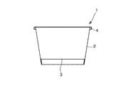
本発明は、紙容器を製造するにあたり、その素材であるブランクの端部を加熱して、ブランクの表面と裏面との少なくとも一方に設けられている熱可塑性樹脂フィルムもしくは樹脂被膜(以下、単に「合成樹脂層」という)を溶融もしくは軟化させるための装置である。その紙容器について説明すると、図12にはその一例を断面図で示してあり、この容器1は外径に対して高さが相対的に低く、開口部が大きい(例えば直径140mm以上)のいわゆるどんぶり型もしくはカップ状の紙容器であり、胴部2および底板部3のいずれもが紙を主体として構成されている。また、上側の開口端には、胴部2の上端縁を外側にカール成形することによるカール部4が形成されており、また下端縁は内側にカール成形することにより底板部3に形成されているフランジ部を巻き込んで底板部3を固定している。そして、その胴部2は上部開口端の径が底部の径より大きい切頭円錐状(テーパー形状)を成しており、その外周面の中心軸線に対する傾斜角は、現在流通している紙容器の傾斜角より比較的大きな角度になっている(例えばテーパー角22°以上)。さらに、この容器1の表面は、予め形成してある合成樹脂層を最終的に紙基材の水分を蒸発させて発泡させることにより、断熱層として機能させることもできるように構成されている。   In producing a paper container, the present invention heats an end of a blank, which is a raw material, to provide a thermoplastic resin film or a resin coating (hereinafter simply referred to as “ It is an apparatus for melting or softening a synthetic resin layer. FIG. 12 shows an example of the paper container in a cross-sectional view. The container 1 has a relatively low height relative to the outer diameter and a large opening (for example, a diameter of 140 mm or more). It is a bowl-shaped or cup-shaped paper container, and both the body portion 2 and the bottom plate portion 3 are mainly composed of paper. Further, a curled portion 4 is formed at the upper opening end by curling the upper end edge of the body portion 2 outward, and the lower end edge is formed at the bottom plate portion 3 by curling inward. The bottom plate portion 3 is fixed by winding the flange portion. And the trunk | drum 2 has comprised the truncated cone shape (taper shape) whose upper opening end diameter is larger than the diameter of a bottom part, and the inclination angle with respect to the central-axis line of the outer peripheral surface is the paper container currently distribute | circulating. The inclination angle is relatively larger than the inclination angle (for example, a taper angle of 22 ° or more). Further, the surface of the container 1 is configured so that a synthetic resin layer formed in advance can function as a heat insulating layer by finally evaporating moisture of the paper base material and foaming.

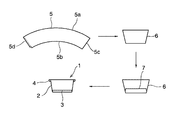
上記の容器1を成形する工程の概略を図13に示してある。先ず、胴部2は、片面もしくは両面に合成樹脂フィルムを両面にラミネート(もしくはコーティング)したブランク5を筒状に丸めて構成されており、そのブランク5はカール成形する前の胴部2を平面に展開した形状すなわちシート状の板紙であり、扇状に開いた(湾曲した)帯状を成し、その幅は容器1の高さ程度になっている。そのブランク5を切頭円錐状に丸め(少なくとも内面側を樹脂面として丸め)、その両端部を重ね合わせて接合することにより筒状のシェル6が成形される。そのシェル6の内部に底紙7が挿入されてシェル6の底部近くに接合される。すなわち、底紙7は、上記のブランク5と同様の板紙を素材とした円盤状の部材であり、その外周部には下向きに折り曲げて形成されたフランジ部が設けられている。この底紙7が挿入されたシェル6の下端縁を内側にカール成形して底紙7のフランジ部を巻き込んで接合することにより底紙7がシェル6に固定される。なお、上端部側のカール部4は底紙7を固定した後に成形される。   An outline of the process of forming the container 1 is shown in FIG. First, the body part 2 is configured by rolling a blank 5 in which a synthetic resin film is laminated (or coated) on one side or both sides into a cylindrical shape, and the blank 5 is a flat surface of the body part 2 before curling. 1 is a sheet-like paperboard, which forms a fan-shaped (curved) belt-like shape, the width of which is about the height of the container 1. The blank 5 is rounded into a truncated cone (rounded at least on the inner surface side as a resin surface), and both ends thereof are overlapped and joined to form a cylindrical shell 6. A bottom paper 7 is inserted into the inside of the shell 6 and joined near the bottom of the shell 6. That is, the bottom paper 7 is a disk-shaped member made of the same paperboard as that of the blank 5 described above, and a flange portion formed by bending downward is provided on the outer peripheral portion thereof. The bottom paper 7 is fixed to the shell 6 by curling the lower end edge of the shell 6 in which the bottom paper 7 is inserted inward and winding the flange portion of the bottom paper 7 together. The curled portion 4 on the upper end side is formed after the bottom paper 7 is fixed.

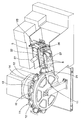
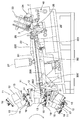
上記の容器1を成形するための装置の一例を説明すると、図6はその全体的な構成を概略的に示しており、この成形機は、水平な軸線を中心に回転させられるターレット10が設けられており、その外周部に複数のマンドレルユニット11が円周方向に一定の間隔を空けて取り付けられている。各マンドレルユニット11は、前述したブランク5を巻き付けて切頭円錐状に成形するためのマンドレル12と、ブランク5をマンドレル12との間に挟み付けて固定するブランククランプ13と、マンドレル12に巻き付けたブランク5における互いに重ね合わせた両端部(すなわちシーム部)を押さえ付けるシームクランプ14とから主に構成されている。   An example of an apparatus for molding the container 1 will be described. FIG. 6 schematically shows the overall configuration, and this molding machine is provided with a turret 10 that is rotated around a horizontal axis. A plurality of mandrel units 11 are attached to the outer periphery of the outer periphery of the mandrel unit 11 at regular intervals in the circumferential direction. Each mandrel unit 11 is wound around the mandrel 12, a mandrel 12 for winding the blank 5 described above to form a truncated cone, a blank clamp 13 for sandwiching and fixing the blank 5 between the mandrel 12, and the mandrel 12. It is mainly comprised from the seam clamp 14 which presses down the both ends (namely, seam part) which mutually overlap | superposed in the blank 5. FIG.

マンドレル12は、成形するべき容器1の形状と同様のテーパー形状の部分を先端側に有し、その中心軸線をターレット10の半径方向に一致させ、かつ小径側をターレット10の半径方向で外周側に向けてターレット10に取り付けられている。図に示す例では、マンドレル12がブランク5に対して図の上から下に移動するように(時計方向に)ターレット10が間欠的に回転しており、図示の状態ではそのマンドレル12の下側すなわちターレット10の回転方向で前方側にブランククランプ13が配置され、これとは反対に図示の状態で上側すなわちターレット10の回転方向で後側にシームクランプ14が配置されている。   The mandrel 12 has a tapered portion similar to the shape of the container 1 to be molded on the distal end side, the central axis thereof is aligned with the radial direction of the turret 10, and the small diameter side is the outer peripheral side in the radial direction of the turret 10. It is attached to the turret 10 toward. In the example shown in the figure, the turret 10 is rotated intermittently (clockwise) so that the mandrel 12 moves from the top to the bottom of the figure with respect to the blank 5, and in the illustrated state, the lower side of the mandrel 12 That is, the blank clamp 13 is disposed on the front side in the rotational direction of the turret 10, and the seam clamp 14 is disposed on the upper side, that is, the rear side in the rotational direction of the turret 10 in the illustrated state.

これらのクランプ13,14は、幅が狭くかつマンドレル12の側面幅とほぼ同じ長さの板状の金属製部材であって(本例では、軽量化のためアルミニウム製部材とする)、後述する図8および図11に示すように、ターレット10に設けられている支点ボルト400,401を中心として揺動するレバー15,16に腕長さを調整可能に取り付けられたアーム17,18の先端部にそれぞれ取り付けられている。クランプ13,14の押圧面の形状はフラットでもよいが、マンドレル12の外周面に沿うように曲面形状にすることが左右のブレを矯正させて均一な押圧力が掛けられるので好ましい。   These clamps 13 and 14 are plate-like metal members having a narrow width and substantially the same length as the side surface width of the mandrel 12 (in this example, aluminum members are used for weight reduction), which will be described later. As shown in FIGS. 8 and 11, the distal ends of the arms 17 and 18 that are attached to the levers 15 and 16 that swing around the fulcrum bolts 400 and 401 provided in the turret 10 so that the arm length can be adjusted. Are attached to each. The pressing surfaces of the clamps 13 and 14 may be flat, but it is preferable to use a curved surface along the outer peripheral surface of the mandrel 12 because the left and right blurs are corrected and a uniform pressing force is applied.

ターレット10は、各マンドレル12の間隔を1ピッチとして間欠的に回転させられるように構成されており、各マンドレル12はその中心軸線が水平になる位置で一時的に止められ、そのように止められる位置が給紙位置21となっている。その給紙位置21におけるマンドレル12とブランククランプ13との隙間に滑り込ませるようにブランク5を供給するためのフィーダー22が設けられている。そのブランク5は、容器1の胴部を形成する素材であって、図13に示すように、扇状に湾曲した帯状の板紙であり、フィーダー22はそのブランク5を一枚ずつ、給紙位置21におけるマンドレル12の下側に供給するように構成されている。   The turret 10 is configured to be intermittently rotated with the interval between the mandrels 12 as one pitch, and each mandrel 12 is temporarily stopped at a position where the central axis is horizontal, and is stopped as such. The position is the paper feed position 21. A feeder 22 for supplying the blank 5 is provided so as to slide into the gap between the mandrel 12 and the blank clamp 13 at the paper feeding position 21. The blank 5 is a material for forming the body portion of the container 1 and is a strip-shaped paper board that is curved in a fan shape as shown in FIG. 13. The feeder 22 feeds the blank 5 one by one to the paper feeding position 21. It is comprised so that it may supply to the lower side of the mandrel 12 in.

具体的に説明すると、図7に示すように、フィーダー22は、所定の間隔を空けて互いに平行に配置された複数本のガイドレール220,221と、それらのガイドレール220,221の間をガイドレール220,221と平行に走行するように配置された上側フィードベルトB1と下側フィードベルトB2とを備えており、フィードラインFの上に載せたブランク5を上下のフィードベルトB1,B2により挟んで給紙位置21の方向へ間欠移動させるように構成されている。そして、そのガイドレール220,221あるいはフィードベルトB1,B2の先端部は、給紙位置21で中心軸線を水平にして停止させられているマンドレル12の下側近傍まで延びており、少なくともその位置でマンドレル12の外周面の母線と平行になっている。すなわち、マンドレル12の外周面がテーパー面となっていることにより、水平線に対して傾斜しているその外周面と平行になるように、フィーダー22のフィードラインFも水平線に対して傾斜している。   More specifically, as shown in FIG. 7, the feeder 22 guides between a plurality of guide rails 220 and 221 arranged in parallel with each other at a predetermined interval, and between the guide rails 220 and 221. An upper feed belt B1 and a lower feed belt B2 arranged so as to run parallel to the rails 220 and 221 are provided, and a blank 5 placed on the feed line F is sandwiched between the upper and lower feed belts B1 and B2. Is configured to intermittently move in the direction of the paper feed position 21. The leading end portions of the guide rails 220 and 221 or the feed belts B1 and B2 extend to the vicinity of the lower side of the mandrel 12 that is stopped at the paper feed position 21 with the central axis being horizontal, at least at that position. It is parallel to the generatrix of the outer peripheral surface of the mandrel 12. That is, since the outer peripheral surface of the mandrel 12 is a tapered surface, the feed line F of the feeder 22 is also inclined with respect to the horizontal line so as to be parallel to the outer peripheral surface inclined with respect to the horizontal line. .

上記のガイドレール220,221およびフィードベルトB1,B2は、給紙位置21からターレット10の半径方向で外側に延びており、その後端部の上方には多数枚のブランク5を重ねて収容するブランクスタッカー23が配置されている。このブランクスタッカー23は、上下両側が開口した枠状の部材であって、円弧長が長いことにより凸となっている縁部(図13の5a)が給紙方向で前方側となるようにブランク5を積層して収容するように構成されている。また、ブランクスタッカー23は、その内部のブランク5が水平にならずに、その凸となる縁部5a側が若干上向きに傾斜するように、垂直線(または鉛直線)に対して後方に傾斜して配置されている。さらに、ブランクスタッカー23の下端側には、ブランク5を一枚ずつ引き下げてフィーダー22に供給するための機構40が設けられている。   The guide rails 220 and 221 and the feed belts B1 and B2 extend outward from the paper feeding position 21 in the radial direction of the turret 10 and are placed in a blank space for storing a plurality of blanks 5 stacked on the rear end. A tucker 23 is arranged. The blank stacker 23 is a frame-like member that is open on both the upper and lower sides, and is blank so that the edge (5a in FIG. 13) that is convex due to the long arc length is on the front side in the paper feeding direction. 5 is stacked and accommodated. Further, the blank stacker 23 is inclined backward with respect to the vertical line (or vertical line) so that the blank 5 inside thereof is not horizontal but the convex edge 5a side is inclined slightly upward. Has been placed. Furthermore, a mechanism 40 is provided at the lower end side of the blank stacker 23 for pulling down the blanks 5 one by one and supplying them to the feeder 22.

先ず、ブランクスタッカー23の下端部には、その内部に積層されたブランク5のうち下端部側の複数枚のブランク5における円弧長が短いことにより凹となっている縁部(図13の5b)を押圧するゲージングシリンダ24が設けられている。また、ブランクスタッカー23の下方には、ブランクスタッカー23に積層されているブランク5のうち最も下側のブランク5を吸着して引き下げる吸着パッド25が上下動するように配置されている。この吸着パッド25を上下動させるための機構40は、前述した各クランプ13,14と同様に、ターレット10の回転と同期させるために、ターレット10を回転させる駆動力をカム機構などの適宜の連動機構によって吸着パッド25に伝達するように構成することが好ましい。なお、吸着パッド25によって引き下げられたブランク5を前述したフィードベルトB1,B2に受け渡すために複数のローラ26が適宜の連動機構によって駆動するベースローラ26’に対して上下動し、ブランク5を挟んでフィーダー22に送り込むように設けられている。   First, at the lower end portion of the blank stacker 23, an edge portion that is concave due to the short arc length of the plurality of blanks 5 on the lower end side among the blanks 5 stacked inside (5b in FIG. 13). A gauging cylinder 24 is provided to press the. In addition, below the blank stacker 23, a suction pad 25 that sucks and pulls down the lowermost blank 5 among the blanks 5 stacked on the blank stacker 23 is arranged to move up and down. The mechanism 40 for moving the suction pad 25 up and down, like the above-described clamps 13 and 14, is synchronized with the rotation of the turret 10 so that the driving force for rotating the turret 10 is appropriately interlocked with a cam mechanism or the like. It is preferable to be configured to transmit to the suction pad 25 by a mechanism. In order to deliver the blank 5 pulled down by the suction pad 25 to the above-described feed belts B1 and B2, a plurality of rollers 26 move up and down with respect to the base roller 26 'driven by an appropriate interlocking mechanism, and the blank 5 is moved. It is provided so as to be fed into the feeder 22 with being sandwiched.

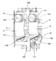
さらに、フィーダー22の途中すなわち給紙位置21とブランクスタッカー23との間にブランク5の互いに重ね合わされて接合される端部を加熱するヒーター27が設けられている。すなわち、ブランク5は合成樹脂でラミネートされているので、その合成樹脂を接着剤として機能させるために、ブランク5の一方の端部の表面(容器1では内面)側と、他方の端部の裏面(容器1では外面)側とを熱風加熱するようになっている。図7にはブランク5の表面側を加熱するヒーター27を示してあるが、図7ではこれとは反対側の裏面側を加熱するヒーターは省略してある。   Further, a heater 27 is provided in the middle of the feeder 22, that is, between the paper feed position 21 and the blank stacker 23, to heat the end portion of the blank 5 that is overlapped and joined. That is, since the blank 5 is laminated with a synthetic resin, in order to make the synthetic resin function as an adhesive, the front surface (the inner surface in the container 1) side of the blank 5 and the back surface of the other end are used. The outer side of the container 1 is heated with hot air. FIG. 7 shows a heater 27 for heating the front surface side of the blank 5, but in FIG. 7, the heater for heating the back surface side opposite to this is omitted.

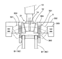
本発明は、そのヒーター27を含む加熱装置に特徴があり、その具体的な構成を更に説明すると、図1は、ヒーター27をフィーダー22の左右に一対ずつ、合計4台のヒーター27を設けた例を示し、ブランク5の進行方向で右側にはブランク5の右端部の上面(容器1された場合には内面)に向けて熱風を吹き付ける2台のヒーター27が、ブランク5の搬送方向に並んで配置されている。また、ブランク5の進行方向で左側にはブランク5の左端部の下面(容器1された場合には外面)に向けて熱風を吹き付ける2台のヒーター27が、ブランク5の搬送方向に並んで配置されている。なお、ブランク5の搬送方向に並んで配置されているヒーター27の間隔は、間欠送りされるブランク5の1ピッチ分の移動量に相当する距離である。このようにヒーター22を複数台設ける理由は、1台のヒーターでは、加熱に時間を要するが、2台のヒーター27で加熱工程を複数にすれば、ブランク5が間欠搬送される途中の短い停止時間で加熱することができるためである。   The present invention is characterized by a heating device including the heater 27. The specific configuration will be further described. In FIG. 1, a total of four heaters 27 are provided, one pair of heaters 27 on the left and right sides of the feeder 22. An example is shown, and two heaters 27 for blowing hot air toward the upper surface (the inner surface when the container 1 is used) of the blank 5 are arranged in the conveyance direction of the blank 5 on the right side in the traveling direction of the blank 5. Is arranged in. In addition, two heaters 27 for blowing hot air toward the lower surface of the left end portion of the blank 5 (the outer surface in the case of the container 1) are arranged side by side in the conveyance direction of the blank 5 on the left side in the traveling direction of the blank 5. Has been. In addition, the space | interval of the heater 27 arrange | positioned along with the conveyance direction of the blank 5 is a distance corresponded to the movement amount for 1 pitch of the blank 5 intermittently fed. The reason why a plurality of heaters 22 are provided in this way is that it takes time to heat with one heater, but if the heating process is made plural with two heaters 27, a short stop in the middle of intermittent conveyance of the blank 5 It is because it can heat in time.

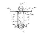
各ヒーター27は、供給された空気を加熱して上向きもしくは下向きに噴射するように構成されており、その具体的な構成の一例を図2に示してある。このヒーター27は全体として円筒状をなしており、軸線方向での一端側の外周面に吸気口27aが形成され、また軸線方向での一方の端面の中央部に噴射口27bが形成されている。その吸気口27aに、図示しないコンプレッサーなどのエア源から空気が供給されるように構成されている。また、ヒーター27の内部には、径の異なる複数の円筒状の仕切板27cが設けられており、それらの仕切板27cの軸線方向で互いに異なる端部側に、板厚方向に貫通する貫通孔27dが形成されている。そして、上記の吸気口27aは最外周側の仕切板27cの外周部に開口し、また噴射口27bは最内周側の仕切板27cの内周部に開口しており、したがって吸気口27aと噴射口27bとの間に、軸線方向に上昇・下降を繰り返すエア通路27eが形成されている。   Each heater 27 is configured to heat the supplied air and inject it upward or downward, and an example of the specific configuration is shown in FIG. The heater 27 has a cylindrical shape as a whole, and an air inlet 27a is formed on the outer peripheral surface at one end in the axial direction, and an injection port 27b is formed at the center of one end surface in the axial direction. . Air is supplied to the intake port 27a from an air source such as a compressor (not shown). In addition, a plurality of cylindrical partition plates 27c having different diameters are provided inside the heater 27, and through holes that penetrate in the plate thickness direction at different end sides in the axial direction of the partition plates 27c. 27d is formed. The intake port 27a is opened to the outer peripheral portion of the outermost peripheral partition plate 27c, and the injection port 27b is opened to the inner peripheral portion of the innermost peripheral partition plate 27c. An air passage 27e that repeats rising and lowering in the axial direction is formed between the injection port 27b.

そして、そのエア通路27eの途中に空気を加熱して昇温させるための発熱部材が設けられている。具体的には、最内周側の仕切板27cの外周部と、内周側から二番目の仕切板27cの外周部とに電熱線(電熱コイル)27fが取り付けられており、ここを流れる空気を加熱するとともに仕切板27cを加熱してその内外周側を流れる空気を加熱するように構成されている。なお、電熱コイル27fの電流制御は、図示しない適宜のコントローラによって行うことができ、例えば噴射口27bやその近傍での温度を図示しないセンサで検出し、その温度が目標温度となるように電熱コイル27fの電流を制御するように構成することができる。   A heating member is provided in the middle of the air passage 27e to heat the air and raise the temperature. Specifically, a heating wire (electric heating coil) 27f is attached to the outer peripheral portion of the innermost peripheral partition plate 27c and the outer peripheral portion of the second partition plate 27c from the inner peripheral side, and the air flowing therethrough And the partition plate 27c are heated to heat the air flowing on the inner and outer peripheral sides. The current control of the electric heating coil 27f can be performed by an appropriate controller (not shown). For example, the electric heating coil 27b and its vicinity are detected by a sensor (not shown) and the temperature is set to the target temperature. It can be configured to control the current of 27f.

上記の噴射口27bから噴出された熱風をブランク5の長手方向における端部に吹き付けるためのノズル27gが設けられている。このノズル27gは、ホットエアを帯状に絞ってブランク5の端部における限られた範囲に吹き付けるためのものであり、したがってその開口部27hは、ブランク5の幅より僅かに長く、かつブランク5の加熱するべき端部の幅より僅かに広い幅の矩形状に形成されている。そして、そのノズル27gは、前述したフィーダー22によって間欠的に搬送されるブランク5における長手方向での両端部に対向する位置に固定配置されている。その状態を図3に示してあり、ノズル27gの開口部27hは、ブランク5の長手方向での端縁から所定寸法の小さい幅の領域を加熱部としてその加熱部と平行に配置されている。なお、ノズル27gとブランク5との間隔は、搬送中のブランク5がノズル27gに接触せず、またノズル27gから吹き出したホットエアが不必要に拡散しない程度の小さい間隔に設定されている。   There is provided a nozzle 27g for blowing hot air ejected from the ejection port 27b to the end of the blank 5 in the longitudinal direction. This nozzle 27g is used to squeeze hot air into a band and spray it to a limited area at the end of the blank 5, and therefore the opening 27h is slightly longer than the width of the blank 5 and the blank 5 is heated. It is formed in a rectangular shape that is slightly wider than the width of the end portion to be made. The nozzle 27g is fixedly disposed at a position facing both ends in the longitudinal direction of the blank 5 intermittently conveyed by the feeder 22 described above. The state is shown in FIG. 3, and the opening 27 h of the nozzle 27 g is arranged in parallel with the heating portion with a region having a small width from the edge in the longitudinal direction of the blank 5 as a heating portion. In addition, the space | interval of the nozzle 27g and the blank 5 is set to such a small space | interval that the blank 5 in conveyance does not contact the nozzle 27g, and the hot air blown out from the nozzle 27g does not spread | diffuse unnecessarily.

上記のヒーター27は、ブランク5の長手方向における両端部を加熱し、その限られた領域の熱可塑性合成樹脂(例えば、ポリエチレンなど)を溶融もしくは軟化させるためのものであり、これに対してブランク5の表裏両面の全体に合成樹脂層が設けられているので、限られた領域を超えて合成樹脂を加熱して溶融もしくは軟化させないようにするために熱遮断部材が設けられている。その理由は、所定領域以外の樹脂が加熱溶融もしくは軟化して発泡しまうと、樹脂が搬送面に擦れて付着しブランクが傷付いたり、ブランクの搬送性が悪くなったりするため、所定の領域外に熱風の熱が伝わるのを防ぐためである。その熱遮断部材の一例を図4および図5を参照して説明すると、ここに示す例では、ブランク5の表面(上面)に接触ないし接近させられる左右二対(合計4つ)の熱遮断バー101,102,103,104、およびブランク5の裏面(下面)側に固定配置されている熱遮断走行板120,121によって熱遮断部材が構成されている。これらの熱遮断バー101〜104は、フィーダー22によって間欠的に搬送されるブランク5の左右両端縁と平行に配置されており、したがってブランク5の搬送方向での左側(もしくは右側)に配置されている熱遮断バー101,103と、右側(もしくは左側)に配置されている熱遮断バー102,104とは、ブランク5の左右両端縁と同様に、ブランク5の搬送方向に対して扇状に開いた状態に配置されている。なお、熱遮断バー101,103同士、熱遮断バー102,104同士は互いに平行になっている。また、熱遮断バー101,103同士の間隔、および熱遮断バー102,104同士の間隔は、ブランク5を間欠的に搬送する1ピッチの送り量と同じに設定されている。したがって、一対の熱遮断バー101,102に対応する位置にブランク5が停止している状態では、他の一対の熱遮断バー103,104に対応する位置にブランク5が停止しているように構成されている。すなわち、フィーダー22の左右両側にそれぞれ2台のヒーター27が設けられていることに対応して左右に二対の熱遮断バー101〜104が設けられている。   The heater 27 is for heating both ends of the blank 5 in the longitudinal direction to melt or soften a limited area of thermoplastic synthetic resin (for example, polyethylene). Since the synthetic resin layers are provided on both the front and back surfaces of the sheet 5, a heat blocking member is provided to prevent the synthetic resin from being heated and melted or softened beyond a limited region. The reason is that if the resin outside the specified area is heated and melted or softened and foamed, the resin will rub against and adhere to the transfer surface and the blank may be damaged or the transferability of the blank may deteriorate. This is to prevent the heat of hot air from being transmitted. An example of the heat blocking member will be described with reference to FIGS. 4 and 5. In the example shown here, two pairs of left and right (four in total) heat blocking bars which are brought into contact with or approach the surface (upper surface) of the blank 5. 101, 102, 103, 104 and the heat insulation traveling plates 120, 121 fixedly arranged on the back surface (lower surface) side of the blank 5 constitute a heat insulation member. These heat shielding bars 101 to 104 are arranged in parallel with the left and right edges of the blank 5 that is intermittently conveyed by the feeder 22, and are therefore arranged on the left side (or right side) in the conveyance direction of the blank 5. The heat shielding bars 101 and 103 and the heat shielding bars 102 and 104 arranged on the right side (or left side) are opened in a fan shape with respect to the conveyance direction of the blank 5, similarly to the left and right edges of the blank 5. Arranged in a state. Note that the heat shield bars 101 and 103 and the heat shield bars 102 and 104 are parallel to each other. Moreover, the space | interval of heat insulation bar | burr 101,103 and the space | interval of heat | fever insulation bar | burr 102,104 are set to the same feed amount of 1 pitch which conveys the blank 5 intermittently. Therefore, in a state where the blank 5 is stopped at a position corresponding to the pair of heat shield bars 101, 102, the blank 5 is stopped at a position corresponding to the other pair of heat shield bars 103, 104. Has been. That is, two pairs of heat blocking bars 101 to 104 are provided on the left and right sides corresponding to the two heaters 27 provided on the left and right sides of the feeder 22 respectively.

図4および図5に示すように、ブランク5の搬送方向での左側に配置されている熱遮断バー101,103は、ブランク5に対して上側に配置されるとともに、ブランク5の下側には、熱遮断走行板120がノズル27gに隣接して中央側に固定配置されている。一方、ブランク5の搬送方向の右側に配置されている熱遮断バー102,104は、ブランク5に対して上側に配置され、ノズル27gに隣接して中央側に配置されるとともに、ブランク5の下側には、熱遮断走行板121がノズル27gに対向して中央側に固定配置されている。   As shown in FIGS. 4 and 5, the heat shielding bars 101 and 103 arranged on the left side in the conveyance direction of the blank 5 are arranged on the upper side with respect to the blank 5 and on the lower side of the blank 5. The heat shield travel plate 120 is fixedly disposed on the center side adjacent to the nozzle 27g. On the other hand, the heat shield bars 102 and 104 arranged on the right side in the conveyance direction of the blank 5 are arranged on the upper side with respect to the blank 5, arranged on the center side adjacent to the nozzle 27 g, and below the blank 5. On the side, a heat shield travel plate 121 is fixedly disposed on the center side facing the nozzle 27g.

それぞれ熱遮断バー101,103は所定形状のフレーム部材105の一部として一体化されており、他方の熱遮断バー102,104はフレーム部材106の一部として一体化されている。そして、間欠的に停止しているブランク5の表面に接触ないし接近させられ、ブランク5が搬送される際には後述する駆動機構によりブランク5の表面から上方に離れるように構成され、ブランク5の搬送される隙間を広くしブランク5に溶融もしくは軟化した樹脂が搬送面に付着するのを防止している。なお、ヒーター27に対向して設けられている熱遮断走行板121および熱遮断バー102,104は、熱風の噴射の力でブランク5の両端部が押し曲げられてしまうのを防止して、フラット状態でブランク5を搬送できるようにするためでもある。   Each of the heat shield bars 101 and 103 is integrated as a part of a frame member 105 having a predetermined shape, and the other heat shield bars 102 and 104 are integrated as a part of the frame member 106. And it is comprised so that it may be made to contact or approach the surface of the blank 5 which has stopped intermittently, and when the blank 5 is conveyed, it will leave | separate upward from the surface of the blank 5 with the drive mechanism mentioned later, The gap to be conveyed is widened to prevent the molten or softened resin in the blank 5 from adhering to the conveying surface. The heat shield travel plate 121 and the heat shield bars 102 and 104 provided to face the heater 27 are flat against the both ends of the blank 5 being pushed and bent by the force of hot air injection. It is also for enabling the blank 5 to be conveyed in the state.

そして、ノズル27gの開口部27hに隣接して配置されている熱遮断バー102,104および熱遮断走行板120は、間欠的に搬送されるブランク5の左右の両端部をホットエア(合成樹脂の融点近くの温度、例えば、130℃程度の熱風)に対して露出させるような配置関係にあって、それより中心側の領域に熱風による熱の伝播を防ぐように構成されている。したがって、これら各熱遮断バー101〜104および熱遮断走行板120,121の内部には冷却水路(図示せず)が形成されており、フレーム105,106に設けられている給排水ポート107,108および熱遮断走行板120,121に設けられている給排水ポート122,123を介して冷却水を連続的に流通させることにより、熱遮断バー101〜104および熱遮断走行板120,121を冷却するように構成されている。すなわち、本発明における冷却機構が設けられている。これは、熱遮断バー101〜104および熱遮断走行板120,121を経由してブランク5に対して熱が伝わってブランク5が不必要に加熱されることを回避して、樹脂の発泡を防ぐとともに、樹脂カスや紙粉が搬送面に付着したり堆積したりすることを防止するためである。なお、各熱遮断バー101〜104および熱遮断走行板120,121のうち、熱遮断バー101,103および熱遮断走行板121には、外側に向けて放熱用のフィン109がそれぞれ形成され、冷却機能に加えて放熱機能も備えている。   The heat shield bars 102 and 104 and the heat shield travel plate 120 arranged adjacent to the opening 27h of the nozzle 27g are connected with hot air (melting point of the synthetic resin) at the left and right ends of the blank 5 that is intermittently conveyed. It is arranged so as to be exposed to a nearby temperature (for example, hot air of about 130 ° C.), and is configured to prevent heat from being transmitted by the hot air to a region closer to the center. Therefore, a cooling water channel (not shown) is formed inside each of the heat blocking bars 101 to 104 and the heat blocking traveling plates 120 and 121, and the water supply / drain ports 107 and 108 provided in the frames 105 and 106, and As the cooling water is continuously circulated through the water supply / drain ports 122 and 123 provided in the heat shield travel plates 120 and 121, the heat shield bars 101 to 104 and the heat shield travel plates 120 and 121 are cooled. It is configured. That is, the cooling mechanism in the present invention is provided. This prevents heat from being transmitted to the blank 5 via the heat blocking bars 101 to 104 and the heat blocking traveling plates 120 and 121, thereby heating the blank 5 unnecessarily and preventing foaming of the resin. At the same time, it is for preventing resin residue and paper dust from adhering to or accumulating on the conveying surface. Of the heat shield bars 101 to 104 and the heat shield travel plates 120 and 121, the heat shield bars 101 and 103 and the heat shield travel plate 121 are respectively provided with heat dissipating fins 109 toward the outside for cooling. In addition to the function, it also has a heat dissipation function.

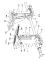
次に、各熱遮断バー101〜104を、それぞれ取り付けているフレーム105,106を介して上下動させる駆動機構110について説明すると、フィーダー22の左右両側には、側板111,112が立設されており、それぞれの側板111,112には上下方向に直線的に案内移動させるスライダ113,114が取り付けられており、その各スライダ113,114の上端部に、前述したフレーム105,106が取り付けられている。また、各側板111,112の下側は、それらの側板111,112を貫通するように揺動軸115が配置されており、その揺動軸115のうち各側板111,112に近い位置には、アーム116,117が取り付けられ、そのアーム116,117とそれぞれに対応するフレーム部材105,106とがコネクションロッド118,119によって連結されている。したがって、揺動軸115が、図4に示すように、オシレータ(図示せず)により左右に回動することによって、フレーム部材105,106がコネクションロッド118,119を介してスライダ113,114に沿って上下方向に移動するように構成されている。   Next, the drive mechanism 110 that moves the heat shield bars 101 to 104 up and down via the attached frames 105 and 106 will be described. Side plates 111 and 112 are erected on the left and right sides of the feeder 22. In addition, sliders 113 and 114 that are linearly guided and moved in the vertical direction are attached to the side plates 111 and 112, respectively, and the above-described frames 105 and 106 are attached to the upper ends of the sliders 113 and 114, respectively. Yes. In addition, a swing shaft 115 is disposed below the side plates 111 and 112 so as to pass through the side plates 111 and 112, and the swing shaft 115 is located near the side plates 111 and 112. The arms 116 and 117 are attached, and the arm members 116 and 117 are connected to the corresponding frame members 105 and 106 by connection rods 118 and 119, respectively. Therefore, as shown in FIG. 4, the swing shaft 115 is rotated left and right by an oscillator (not shown), so that the frame members 105 and 106 are moved along the sliders 113 and 114 via the connection rods 118 and 119, respectively. Are configured to move up and down.

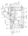
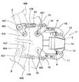
つぎに、前記ターレット10やその外周部に一定間隔で取り付けられたマンドレル12などを主体とする成形機の構成について更に具体的に説明すると、前記クランプ13,14が取り付けられているそれぞれのアーム17,18の中間部分には、図8に示すように、コネクションダンパ19,20の一方の端部が連結されており、またそのコネクションダンパ19,20の他方の端部は、ターレット10に設けられている支点ボルト402,403を中心に回動するレバー404,405に連結されている。それらのコネクションダンパ19,20には、クランプ13,14がマンドレル12に対してブランク5を所定の押圧力で固定できるようにバネ406が内装されている。また、マンドレル12に圧接したときの衝撃力を緩和するための緩衝機能を備えている。なお、マンドレル12に対する前記各クランプ13,14の押圧力をマンドレル12の母線方向で均一化させるために、アーム17,18には、各クランプ13,14の背面と当接するストッパーPが、高さ(α)を調整可能に設けられている。   Next, the configuration of the molding machine mainly including the turret 10 and a mandrel 12 attached to the outer periphery of the turret 10 at regular intervals will be described in more detail. Each arm 17 to which the clamps 13 and 14 are attached is described. , 18 is connected to one end of connection dampers 19, 20 as shown in FIG. 8, and the other end of the connection dampers 19, 20 is provided on the turret 10. It is connected to levers 404 and 405 that rotate around supporting fulcrum bolts 402 and 403. The connection dampers 19 and 20 are provided with springs 406 so that the clamps 13 and 14 can fix the blank 5 to the mandrel 12 with a predetermined pressing force. In addition, a buffer function is provided for alleviating the impact force when pressed against the mandrel 12. In order to make the pressing force of the clamps 13 and 14 against the mandrel 12 uniform in the direction of the generatrix of the mandrel 12, the arms 17 and 18 are provided with stoppers P that are in contact with the back surfaces of the clamps 13 and 14. (Α) is provided to be adjustable.

一方、コネクションダンパ19,20を作動させるレバー404,405には、カムフォロアー407,407が設けられ、これらのカムフォロアー407,407は、ブランククランプ13用の溝カム408の環状のカム溝Bと、シームクランプ用の溝カム409の環状のカム溝Sとにそれぞれ係合されている。そして、溝カム408と409は、ターレット10と同軸上に設けられている。したがって、ターレット10の回転に従ってカムフォロアー407,407はカム溝Bおよびカム溝Sに係合した状態で周回できるように構成されている。この溝カム408,409は、ターレット10の両側(紙面の表側と裏側)にそれぞれ配置され、オシレータ駆動系(図示せず)により溝カム自体をターレット10の軸を中心に所定の振り角度でそれぞれ別々のタイミングで揺動できるように図示しないリンクで連結制御されている。この溝カム408,409は、このように各クランプ13,14を独立した溝カム機構によりマンドレル12に対して別々な開閉動作ができるようにしておけば、ブランククランプ13については、ブランク5をマンドレル12との間に挟み付けるだけなのでブランククランプ13とマンドレル5の隙間を大きく設定する必要がなく小さなストロークで充分であるのに対して、シームクランプ14の方は、ブランク5の両端をマンドレル12に巻き付けて互いに重ね合わせる際に、シームクランプ14が邪魔にならない程度にマンドレル12から離しておく必要がありブランククランプ13よりも大きなストロークを確保することができる。勿論、同じストロークでも差し支えないが、クランプの加速度などの慣性力を調整する上でも別々な開閉機構にしておくのが望ましい。   On the other hand, the levers 404 and 405 for operating the connection dampers 19 and 20 are provided with cam followers 407 and 407, which are connected to the annular cam groove B of the groove cam 408 for the blank clamp 13. Are engaged with the annular cam groove S of the groove cam 409 for the seam clamp. The groove cams 408 and 409 are provided coaxially with the turret 10. Therefore, the cam followers 407 and 407 are configured so as to be able to circulate while being engaged with the cam groove B and the cam groove S according to the rotation of the turret 10. The groove cams 408 and 409 are disposed on both sides (the front side and the back side of the paper surface) of the turret 10, respectively, and the groove cam itself is centered around the axis of the turret 10 by an oscillator drive system (not shown). The connection is controlled by a link (not shown) so that it can swing at different timings. If the groove cams 408 and 409 are configured so that the clamps 13 and 14 can be separately opened and closed with respect to the mandrel 12 by the independent groove cam mechanism, the blank 5 is replaced with the mandrel. The gap between the blank clamp 13 and the mandrel 5 does not need to be set large, and a small stroke is sufficient. On the other hand, the seam clamp 14 has both ends of the blank 5 attached to the mandrel 12. When wrapping and overlapping each other, it is necessary to keep the seam clamp 14 away from the mandrel 12 to the extent that the seam clamp 14 does not get in the way, and a larger stroke than the blank clamp 13 can be secured. Of course, the same stroke may be used, but it is desirable to use separate opening / closing mechanisms for adjusting the inertial force such as the acceleration of the clamp.

こうすることによって、シームクランプ14の動作とブランククランプ13の動作を、それぞれに適した条件でマンドレル12に対して開閉動作を行うことができる。また、設備面では、一つのターレット10の両側に溝カム機構を配置し、環状の溝カムに従って周回する各クランプの開閉を溝カムの振り角で簡単に開閉制御することができるため、装置を大型化することなくマンドレル12毎にブランククランプ13とシームクランプ14との両方を設けることが可能となる。   By doing so, the operation of the seam clamp 14 and the operation of the blank clamp 13 can be performed on the mandrel 12 under conditions suitable for each. In terms of equipment, a groove cam mechanism is arranged on both sides of one turret 10, and the opening and closing of each clamp that circulates according to the annular groove cam can be easily controlled by the swing angle of the groove cam. Both the blank clamp 13 and the seam clamp 14 can be provided for each mandrel 12 without increasing the size.

更に加えて、図8に示すように、ブランククランプ13の駆動機構はターレット10の裏側に設けられ、これに対してシームクランプ14の駆動機構はターレット10の表側に設けられている。そして各クランプ用の溝カム408,409はターレット10が間欠停止している時に動かされてカム溝Bおよびカム溝Sに従ってレバー404,405を揺動させ、それに伴い、コネクションダンパ19,20を介して各クランプ13,14がマンドレル12に対して「開」「閉」の動作が行われるように操作制御されている。このように溝カム408,409および駆動機構がターレット10の表裏両側にそれぞれ配置されることによりターレット10に対する偏荷重が抑制できる(各クランプ圧によるカム溝B,Sに掛かる反力のバランスがとれる)。その結果、カム溝B,Sをカムフォロアー407,407がスムーズに周回でき、しかもマンドレル12の母線方向(ブランク5の接合部)に対するシームクランプ14の捩れの発生を防止することが可能となる。   In addition, as shown in FIG. 8, the drive mechanism of the blank clamp 13 is provided on the back side of the turret 10, while the drive mechanism of the seam clamp 14 is provided on the front side of the turret 10. The groove groove cams 408 and 409 for each clamp are moved when the turret 10 is intermittently stopped to swing the levers 404 and 405 according to the cam groove B and the cam groove S, and accordingly, via the connection dampers 19 and 20. Thus, the clamps 13 and 14 are controlled to perform an “open” and “close” operation on the mandrel 12. As described above, the groove cams 408 and 409 and the drive mechanism are arranged on both the front and back sides of the turret 10 so that the uneven load on the turret 10 can be suppressed (the reaction force applied to the cam grooves B and S by each clamp pressure can be balanced). ). As a result, the cam followers 407 and 407 can smoothly circulate in the cam grooves B and S, and it is possible to prevent the seam clamp 14 from being twisted in the busbar direction of the mandrel 12 (joint portion of the blank 5).

なお、コネクションダンパ19,20の駆動をカム手段によって行わせているが、本例に限定されず、ターレット10の回転停止中に動作させる機構であれば特に制限はなく、ターレット10の機構とは別個の駆動機構を備えた、その他の適宜の連動機構、例えばアクチュエータによって各コネクションダンパ19,20に駆動力を伝達するように構成してもよい。   Although the connection dampers 19 and 20 are driven by cam means, the present invention is not limited to this example, and there is no particular limitation as long as it is a mechanism that operates while rotation of the turret 10 is stopped. What is the mechanism of the turret 10? You may comprise so that a driving force may be transmitted to each connection damper 19 and 20 with another appropriate interlocking mechanism provided with a separate drive mechanism, for example, an actuator.

一方、前述した給紙位置21にはブランク5を所定の位置および姿勢に位置決めするための位置決め手段が設けられている。すなわち、図9に示すように、フィードベルトB1,B2の先端側には、マンドレル12の下側近傍まで送られたブランク5を最終的にマンドレル12の真下まで短いストロークで押し込み、ストッパー301に当てて位置決めさせる押し込み爪300がマンドレル12の左右両側に設けられている。それらの押し込み爪300は、適宜のアクチュエータによって軸300′(図7参照)を中心に前後方向に移動させる構成にしてもよいが、ターレット10の回転など他の機構との連動を確実に行うために、ターレット10を回転させる駆動力をカム機構などの適宜の運動機構によって各押し込み爪300に伝達するように構成することが好ましい。また、その給紙位置21の左右両側には、前記フィーダー22により送られてくるブランク5を給紙位置21に保持させるテーブル302が設けられており、ブランク5の両端部の樹脂被膜が溶融もしくは軟化した状態にあるため、ブランク5の両端部がテーブル302表面に直接接触しないように、テーブル302の上面には、ブランク5の両端部を僅かに浮かせて保持するために少し凸状に形成された吸引部304がマンドレル12の左右両側に設けられている。なお、この吸引部304の表面には、吸着力をブランク5の下面に付与し、ブランク5をほぼ平らな姿勢で保持するための吸引孔が複数形成され、図示しない真空源と連動している。また、ブランク5の左右両側の位置決めを行うサイドガイド303が位置調整可能に設けられている。   On the other hand, a positioning means for positioning the blank 5 at a predetermined position and posture is provided at the paper feed position 21 described above. That is, as shown in FIG. 9, the blank 5 fed to the vicinity of the lower side of the mandrel 12 is finally pushed into the front side of the feed belts B <b> 1 and B <b> 2 with a short stroke to just below the mandrel 12 and hits the stopper 301. The pushing claws 300 for positioning are provided on both the left and right sides of the mandrel 12. These pushing claws 300 may be configured to be moved in the front-rear direction around a shaft 300 ′ (see FIG. 7) by an appropriate actuator. However, in order to reliably interlock with other mechanisms such as rotation of the turret 10. In addition, it is preferable that the driving force for rotating the turret 10 is transmitted to each pushing claw 300 by an appropriate motion mechanism such as a cam mechanism. Further, on both the left and right sides of the paper feed position 21, tables 302 for holding the blank 5 sent by the feeder 22 at the paper feed position 21 are provided, and the resin coating on both ends of the blank 5 is melted or Since the both ends of the blank 5 are not in direct contact with the surface of the table 302, the upper surface of the table 302 is formed in a slightly convex shape so that the both ends of the blank 5 are slightly floated and held. The suction portions 304 are provided on both the left and right sides of the mandrel 12. Note that a plurality of suction holes are formed on the surface of the suction portion 304 to apply suction force to the lower surface of the blank 5 and hold the blank 5 in a substantially flat posture, and are linked to a vacuum source (not shown). . Further, side guides 303 for positioning the left and right sides of the blank 5 are provided so that the position can be adjusted.

そして、図10に示すように、前記テーブル302の下方には、マンドレル12が図の下側に移動することに伴って、ブランククランプ13によって挟み付けられたブランク5の左右両側を相対的に押し上げて、ブランク5をいわゆる「U」の字状に曲げるブラシ付きガイドバー28,28がブラシ28’,28’を内側に向けて設けられている。なお、ブラシ28’,28’はブランク5の傷付きを防止するためのものであり、適宜の軟質材に置き換えてもよい。このガイドバー28は、下側に移動するマンドレル12の外周面とブラシ28’とが接触する程度に間隔を空けてマンドレル12の左右両側に配置され、かつマンドレル12の大径側と小径側のそれぞれに所定の間隔を空けてほぼ平行に配置されて固定された複数の帯状(もしくは棒状)の部材によって構成されている。そして、そのガイドバー28は、前述したフィーダー22の先端側にある給紙位置21におけるブランク5のテーブル302下面を上端(始端部)とし、ここからマンドレル12の旋回方向にその旋回半径とほぼ等しい半径で湾曲した円弧状に形成されている。すなわち、給紙位置21に位置決めされているブランク5をマンドレル12が押し下げることにより、ガイドバー28がそのブランク5の両端部を相対的に押し上げ、その結果、ブランク5をその外周面を傷付けることなく「U」字状に湾曲させるように構成されている。   Then, as shown in FIG. 10, the left and right sides of the blank 5 sandwiched between the blank clamps 13 are relatively pushed up under the table 302 as the mandrel 12 moves downward in the figure. Thus, guide bars 28, 28 with brushes for bending the blank 5 into a so-called "U" shape are provided with the brushes 28 ', 28' facing inward. The brushes 28 ′ and 28 ′ are for preventing the blank 5 from being damaged, and may be replaced with an appropriate soft material. The guide bars 28 are arranged on both the left and right sides of the mandrel 12 so that the outer peripheral surface of the mandrel 12 moving downward and the brush 28 ′ are in contact with each other, and on the large diameter side and the small diameter side of the mandrel 12. Each is constituted by a plurality of strip-shaped (or rod-shaped) members arranged and fixed substantially in parallel with a predetermined interval. The guide bar 28 has the lower surface of the table 302 of the blank 5 at the paper feed position 21 on the front end side of the feeder 22 as the upper end (starting end portion), and from here on, the turning radius of the mandrel 12 is substantially equal to the turning radius. It is formed in an arc shape curved with a radius. That is, when the mandrel 12 pushes down the blank 5 positioned at the paper feed position 21, the guide bar 28 relatively pushes up both ends of the blank 5, and as a result, the blank 5 is not damaged on the outer peripheral surface. It is configured to be bent in a “U” shape.

そのガイドバー28の下端側(終端部側)で、各マンドレル12の間隔とほぼ等しい間隔だけ、前記給紙位置21から下がった位置に、「U」字状に曲げられているブランク5の左右両側を更にマンドレル12に向けて押すことによりマンドレル12に巻き付ける巻き付け爪29が配置されている(図11参照)。この巻き付け爪29は、上記の給紙位置21から1ピッチ、下側に回転して停止しているマンドレル12の両側に配置され、前記ガイドバー28を構成している帯状材(もしくは棒状材)の間からマンドレル12の外周面に沿って進退するように構成されている。この巻き付け爪29は、適宜のアクチュエータによって前後動させるように構成してもよいが、ターレット10の回転など他の機構との連動を確実に行うために、ターレット10を回転させる駆動力をカム機構などの適宜の連動機構によって各プッシュロッドに伝達するように構成することが好ましい。   On the lower end side (terminal end side) of the guide bar 28, the left and right sides of the blank 5 bent in a “U” shape at a position approximately equal to the interval between the mandrels 12 and lowered from the paper feeding position 21. A winding claw 29 is disposed to wind the mandrel 12 by pressing both sides toward the mandrel 12 (see FIG. 11). The winding claws 29 are arranged on both sides of the mandrel 12 that is rotated downward by 1 pitch from the paper feeding position 21 and is a strip-shaped material (or rod-shaped material) constituting the guide bar 28. It is comprised so that it may advance / retreat along the outer peripheral surface of the mandrel 12 from between. The winding claw 29 may be configured to be moved back and forth by a suitable actuator. However, in order to reliably interlock with other mechanisms such as rotation of the turret 10, a driving force for rotating the turret 10 is applied to the cam mechanism. It is preferable to be configured to transmit to each push rod by an appropriate interlocking mechanism such as.

つぎに上述した成形機の作用について説明する。図13に示す扇状に開いた帯状をなすブランク5は、その凸となっている縁部5aがフィード方向での前方側となるようにブランクスタッカー23に積層されて収容されており、その下側の複数枚がゲージングシリンダ24によってブランクスタッカー23との間に挟み付けられているので、積層されたブランク5がブランクスタッカー23の内部に保持されている。一方、ターレット10は、各マンドレル12の間隔を1ピッチとして間欠的に回転させられており、各マンドレル12がその中心軸線を水平にした状態に前記給紙位置21に順次割り出されている。   Next, the operation of the above-described molding machine will be described. The blank 5 having a fan-shaped strip shape shown in FIG. 13 is stacked and accommodated on the blank stacker 23 so that the convex edge 5a is on the front side in the feed direction. Are sandwiched between the blank stacker 23 by the gauging cylinder 24, so that the stacked blanks 5 are held inside the blank stacker 23. On the other hand, the turret 10 is intermittently rotated with the interval between the mandrels 12 as one pitch, and the mandrels 12 are sequentially indexed to the paper feeding position 21 with the center axis thereof being horizontal.

ブランクスタッカー23における最下端のブランク5に対して前記吸着パッド25が上昇し、そのブランク5を吸着した後、下降することによりブランク5がブランクスタッカー23から引き下げられる。その場合、ブランクスタッカー23が傾斜した状態で保持され、その状態からブランク5の凹となっている縁部5bの下端部を支点として回転させつつ引き下げるので、ブランク5を確実に1枚ずつ取り出しフィードラインF上に乗せることができる。   The suction pad 25 ascends with respect to the blank 5 at the lowermost end of the blank stacker 23, adsorbs the blank 5, and then lowers the blank 5 from the blank stacker 23. In that case, the blank stacker 23 is held in an inclined state, and from that state, the lower end of the edge 5b, which is a concave portion of the blank 5, is pulled down while rotating, so that the blanks 5 are reliably taken out one by one and fed. Can be placed on line F.

吸着パッド25が元の位置に下がると、ブランク5の吸着が解除され、そのブランク5はフィーダー22におけるローラ26によってフィードベルトに受け渡され、給紙位置21に向けて送られる。なお、ターレット10およびこれに取り付けられたマンドレル12が前述したように間欠的に回転していることにより、吸着パッド25によるブランク5の取り出し、およびフィーダー22によるブランク5の送給は間欠的に行われる。ブランク5が移動させられている状態では、前述した熱遮断バー101〜104はフィードラインFから離れており、ブランク5は遮断バー101〜104に干渉することなく前進させられる。そして、フィーダー22上のブランク5は、ヒーター27が設けられている箇所で一時的に停止させられ、これとほぼ同時若しくは相前後して、前述した揺動軸115が揺動することにより各熱遮断バー101〜104がブランク5側に移動し、その端部の表面に接触ないし接近する。その状態では、ブランク5の両端部は各熱遮断バー101〜104と各熱遮断走行板120,121とで覆われ、端縁から所定の幅の領域が熱風に対して露出させられている。各ヒーター27におけるノズル27g,27gは、熱遮断バー102,104および熱遮断走行板120にそれぞれ隣接しており、したがって、ヒーター27から噴射させられた熱風は、ブランク5の一方の端部の表面および他方の端部の裏面に吹き付けられ、その部分を加熱する。その場合、熱風は、冷却された熱遮断バー102,104および熱遮断走行板120に遮られブランク5の中心側に流れることはなく、かつノズル27g,27gと対向する側には、それぞれ冷却された熱遮断バー101,103および熱遮断走行板121によりブランク5の裏面の温度上昇を防ぐことができるので、ブランク5の長手方向での端部のみが加熱され、その部分の合成樹脂が溶融もしくは軟化させられる。したがって、互いに接合されられる端部以外の部分で樹脂が溶融もしくは軟化させられるなどの事態を未然に回避もしくは防止することができる。   When the suction pad 25 is lowered to the original position, the suction of the blank 5 is released, and the blank 5 is transferred to the feed belt by the roller 26 in the feeder 22 and sent toward the paper feeding position 21. Since the turret 10 and the mandrel 12 attached thereto are intermittently rotated as described above, the blank 5 is taken out by the suction pad 25 and the blank 5 is fed by the feeder 22 intermittently. Is called. In the state where the blank 5 is moved, the above-described heat blocking bars 101 to 104 are separated from the feed line F, and the blank 5 is advanced without interfering with the blocking bars 101 to 104. Then, the blank 5 on the feeder 22 is temporarily stopped at a place where the heater 27 is provided, and the above-described swing shaft 115 swings substantially simultaneously with or in parallel with this, so that each heat The blocking bars 101 to 104 move to the blank 5 side and contact or approach the surface of the end portion. In this state, both end portions of the blank 5 are covered with the respective heat shielding bars 101 to 104 and the respective heat shielding traveling plates 120 and 121, and a region having a predetermined width is exposed to the hot air from the edge. The nozzles 27g and 27g in each heater 27 are adjacent to the heat blocking bars 102 and 104 and the heat blocking traveling plate 120, respectively. Therefore, the hot air jetted from the heater 27 is the surface of one end of the blank 5. And it sprays on the back surface of the other edge part, The part is heated. In that case, the hot air is blocked by the cooled heat blocking bars 102 and 104 and the heat blocking traveling plate 120 and does not flow to the center side of the blank 5, and is cooled on the side facing the nozzles 27g and 27g. Since the temperature increase of the back surface of the blank 5 can be prevented by the heat shield bars 101 and 103 and the heat shield traveling plate 121, only the end portion in the longitudinal direction of the blank 5 is heated, and the synthetic resin in that portion is melted or Softened. Therefore, it is possible to avoid or prevent a situation in which the resin is melted or softened at a portion other than the end portions joined to each other.

熱遮断バー101〜104をブランク5に接触ないし接近させた状態での熱風の吹き付け、すなわちブランク5の端部の加熱は、ブランク5の送給が一時的に停止している間の所定時間、実行され、その後、前記揺動軸115が上記の場合とは反対に回転して熱遮断バー101〜104がブランク5から離され、その状態で上下のフィードベルトB1,B2が再度走行して、ブランク5が1ピッチ、前進させられる。フィーダー22によって間欠的に搬送される後続のブランク5は、上述した場合と同様にその両端部の表面あるいは裏面が熱風によって加熱され、その合成樹脂層が溶融もしくは軟化させられる。その都度、熱遮断バー101〜104はブランク5に接触ないし接近させられ、その状態で熱風が吹き付けられるが、各熱遮断バー101〜104および熱遮断走行板120,121の内部には冷却水が流れていて冷却されているので、予め定めた温度以上に上昇することはない。   The blowing of hot air in a state where the heat shut-off bars 101 to 104 are in contact with or close to the blank 5, that is, heating of the end of the blank 5 is performed for a predetermined time while feeding of the blank 5 is temporarily stopped, After that, the rocking shaft 115 rotates in the opposite direction to the above, and the heat shield bars 101 to 104 are separated from the blank 5, and in this state, the upper and lower feed belts B1 and B2 travel again. The blank 5 is advanced by 1 pitch. As in the case described above, the subsequent blank 5 that is intermittently conveyed by the feeder 22 is heated with hot air at the both ends thereof, and the synthetic resin layer is melted or softened. In each case, the heat shield bars 101 to 104 are brought into contact with or close to the blank 5 and hot air is blown in that state, but cooling water is contained inside each of the heat shield bars 101 to 104 and the heat shield traveling plates 120 and 121. Since it is flowing and cooled, it does not rise above a predetermined temperature.

こうしてブランク5は、フィーダー22のフィードベルトB1,B2により給紙位置21におけるマンドレル12の下側近傍まで送られ、続いて、ブランク5の先端部がテーブル302の吸引部304の吸引により、合成樹脂層が溶融もしくは軟化したブランク5の両端部が搬送ガイド等に接触するのを防ぎながら、かつ、サイドガイド303により左右方向の姿勢を矯正し、ブランク5の縁部5bが押し込み爪300により押し込まれ、ブランク5は縁部5aがストッパー301に当たる位置まで押し込まれてマンドレル12の下側に位置決めされる。その場合、フィーダー22が前述したように、マンドレル12の外周面の母線と平行になるように傾斜しているので、ブランク5はマンドレル12の下側でマンドレル12の外周面(もしくはその母線)と平行に位置決めされている。   Thus, the blank 5 is fed to the vicinity of the lower side of the mandrel 12 at the paper feeding position 21 by the feed belts B 1 and B 2 of the feeder 22, and subsequently, the leading end portion of the blank 5 is sucked by the suction portion 304 of the table 302, so While preventing the both ends of the blank 5 whose layer has been melted or softened from coming into contact with the conveyance guide or the like, the lateral guide is corrected by the side guide 303, and the edge 5 b of the blank 5 is pushed in by the push-in claw 300. The blank 5 is pushed down to a position where the edge 5a hits the stopper 301 and positioned below the mandrel 12. In that case, since the feeder 22 is inclined so as to be parallel to the generatrix of the outer peripheral surface of the mandrel 12 as described above, the blank 5 is located on the lower side of the mandrel 12 with the outer peripheral surface of the mandrel 12 (or its generatrix). They are positioned in parallel.

一方、ブランク5が給紙位置21に送られる直前ないし直後に、オシレータ駆動系(図示せず)により溝カム408をターレット10の軸を中心に所定の振り角度で回動させてレバー404を揺動させ、それに伴い、コネクションダンパ19を介してブランククランプ13がマンドレル12に対して「閉」となる方向に動作する。その状態でブランククランプ13が押し上げられて位置決めされたブランク5をマンドレル12の外周面との間に挟み付けてマンドレル12に対して固定する。即ち、マンドレル12の外周面とブランク5とが平行になっており、しかも両者が接近しているので、ブランク5はマンドレル12の外周面に向けて平行移動させられ、給紙方向を変えることなくブランク5の先端と後端とが同時に挟み込まれる。したがって、容器1のテーパー角が大きく、また径に対して高さが低く、それに伴ってブランク5が比較的細長く大きな扇角で帯状に開いた形状(ブランクの両端部が中央位置よりも後方にある形状)であっても、ブランク5がクランプされる際にブランク5のマンドレル12に対する位置や姿勢がずれることがない。   On the other hand, immediately before or after the blank 5 is sent to the paper feeding position 21, the groove cam 408 is rotated around the axis of the turret 10 by a predetermined swing angle by an oscillator drive system (not shown) to swing the lever 404. Accordingly, the blank clamp 13 moves in the direction of “closing” with respect to the mandrel 12 via the connection damper 19. In this state, the blank 5 positioned with the blank clamp 13 pushed up is sandwiched between the outer peripheral surface of the mandrel 12 and fixed to the mandrel 12. That is, since the outer peripheral surface of the mandrel 12 and the blank 5 are parallel to each other and are close to each other, the blank 5 is translated toward the outer peripheral surface of the mandrel 12 without changing the sheet feeding direction. The front end and the rear end of the blank 5 are sandwiched at the same time. Therefore, the taper angle of the container 1 is large and the height is low with respect to the diameter, and accordingly, the blank 5 is relatively long and has a large fan angle and is opened in a band shape (both ends of the blank are located behind the center position). Even when the blank 5 is clamped, the position and posture of the blank 5 with respect to the mandrel 12 are not shifted.

ブランク5がブランククランプ13によってマンドレル12に対して固定されるのと相前後して、ターレット10の回転によってマンドレル12が図の下側に向けて移動(もしくは旋回)する。そのマンドレル12の左右両側にはガイドバー28,28が配置されているから、ブランククランプ13によってマンドレル12に対して固定されているブランク5は、マンドレル12が下降することによりガイドバー28の間に押し込められる状態になり、その結果、ブランク5の左右両側が相対的に押し上げられて、マンドレル12の外周面に沿って「U」字状に曲げられる。ターレット10が1ピッチ、回転してマンドレル12がガイドバー28のほぼ下端部にまで移動すると、ブランク5はほぼ完全に「U」字状に湾曲させられ、マンドレル12のほぼ下半部に密着した状態に巻き付けられる。すなわち、このようなブランク5の曲げ成形が、ブランク5の搬送と並行して行われる。ブランク5をこのように巻き付ける過程でブランク5の外面がガイドバー28に擦れるが、ガイドバー28の側面には前述したブラシ28’などの軟質構造材が設けられているので、ブランク5の表面(容器としての外面)が傷付くことが回避される。   Before and after the blank 5 is fixed to the mandrel 12 by the blank clamp 13, the mandrel 12 moves (or turns) toward the lower side of the figure by the rotation of the turret 10. Since the guide bars 28 are disposed on the left and right sides of the mandrel 12, the blank 5 fixed to the mandrel 12 by the blank clamp 13 is moved between the guide bars 28 when the mandrel 12 is lowered. As a result, the left and right sides of the blank 5 are relatively pushed up and bent into a “U” shape along the outer peripheral surface of the mandrel 12. When the turret 10 is rotated by 1 pitch and the mandrel 12 is moved to almost the lower end of the guide bar 28, the blank 5 is almost completely curved in a “U” shape and is in close contact with the lower half of the mandrel 12. Wound into the state. That is, such bending of the blank 5 is performed in parallel with the conveyance of the blank 5. In the process of winding the blank 5 in this manner, the outer surface of the blank 5 is rubbed against the guide bar 28. Since the side surface of the guide bar 28 is provided with the soft structure material such as the brush 28 'described above, the surface of the blank 5 ( Damage to the outer surface of the container) is avoided.

図10に示すように、マンドレル12が1ピッチ移動した位置は、巻き付け爪29が配置されている位置に対応する位置であり、したがってそのマンドレル12に対して巻き付け爪29が点線の位置まで前進し、「U」字状に曲げられているブランク5の左右両側をマンドレル12の外周面に沿わせて更に湾曲させる。その場合、左右の巻き付け爪29の前進のタイミングが僅かにずれており、その結果、ブランク5の左右の端部のうちの一方が先に曲げられるので、その一方の端部の上に他方の端部が重ね合わされる。なお、各巻き付け爪29の前進のタイミングのズレは、それぞれを駆動する機構の動作タイミングを制御することにより行うか、あるいは巻き付け爪29の長さを異ならせることにより行う。   As shown in FIG. 10, the position where the mandrel 12 has moved by one pitch is a position corresponding to the position where the winding claw 29 is disposed. Therefore, the winding claw 29 moves forward to the dotted line position with respect to the mandrel 12. The left and right sides of the blank 5 bent in a “U” shape are further curved along the outer peripheral surface of the mandrel 12. In that case, the timing of advancement of the left and right winding claws 29 is slightly shifted, and as a result, one of the left and right end portions of the blank 5 is bent first, so that the other end is placed on the one end portion. The ends are overlaid. It should be noted that the deviation of the advance timing of each winding claw 29 is performed by controlling the operation timing of the mechanism that drives each of the winding claws 29, or by varying the length of the winding claw 29.

一方、オシレータ駆動系(図示せず)により溝カム409をターレット10の軸を中心に所定の振り角度で揺動させ、レバー405を揺動させ、それに伴い、コネクションダンパ20を介してシームクランプ14がマンドレル12に対して「閉」となる方向に動作するように制御される。   On the other hand, the groove cam 409 is swung at a predetermined swing angle about the axis of the turret 10 by an oscillator drive system (not shown), and the lever 405 is swung. Accordingly, the seam clamp 14 is connected via the connection damper 20. Is controlled to operate in the direction of “closed” with respect to the mandrel 12.

こうして互いに重なった端部に向けてかつ、左右の巻き付け爪29の間を通ってシームクランプ14が前進し、ブランク5の互いに重ね合わされている端部をマンドレル12との間に均一な押圧力で挟み付ける。その場合、マンドレル12に対するブランク5の位置および姿勢にズレが生じていないので、ブランク5の両端部は、ずれることなく正確に重ね合わされる。こうしてシームクランプ14によって押さえ付けられたブランク5の両端部は、前述したようにヒーター27によって加熱されて、それぞれの互いに対向する面の合成樹脂層が軟化もしくは溶融されているので、その合成樹脂層を接着剤として各端部が互いに接合される。   In this way, the seam clamp 14 advances toward the overlapping end portions and between the left and right winding claws 29, and the end portions of the blank 5 that are overlapped with each other are uniformly pressed against the mandrel 12. Pinch. In this case, since there is no deviation in the position and posture of the blank 5 with respect to the mandrel 12, both end portions of the blank 5 are accurately overlapped without shifting. Both ends of the blank 5 thus pressed by the seam clamp 14 are heated by the heater 27 as described above, and the synthetic resin layers on the mutually opposing surfaces are softened or melted. The ends are bonded to each other using an adhesive.

シームクランプ14がブランク5の互いに重ね合わされた両端部を押さえ付けた後、巻き付け爪29が後退し、その後、マンドレル12はターレット10と共に更に回転し、あるいはマンドレル12が移動を開始するのと相前後して巻き付け爪29が後退する。なお、ブランク5の重ね合わされた両端部が完全に接合するまでには幾分時間を要するので、シームクランプ14によってブランク5の端部を押さえ付けた状態が維持される。また、巻き付け爪29によるブランク5の成形およびシームクランプ14によるいわゆるシーム部の押圧などが行われている間に、後続のマンドレル12に対してもブランク5の供給、ブランククランプ13による把持・固定、「U」字状への曲げ成形などの一連の動作が行われる。   After the seam clamp 14 presses the overlapping ends of the blank 5, the winding claw 29 moves backward, and then the mandrel 12 further rotates with the turret 10, or before and after the mandrel 12 starts moving. Then, the winding claw 29 moves backward. In addition, since it takes some time until both ends of the overlapped blank 5 are completely joined, the state where the end of the blank 5 is pressed by the seam clamp 14 is maintained. In addition, while the blank 5 is formed by the winding claws 29 and the so-called seam portion is pressed by the seam clamp 14, the blank 5 is supplied to the subsequent mandrel 12, held and fixed by the blank clamp 13, A series of operations such as bending into a “U” shape is performed.

したがって、マンドレル12に対するブランク5の巻き付けおよびその両端部の接合の工程と同時に、他のマンドレル12に対するブランク5の供給、その「U」字状の曲げなどの工程が実行され、「U」字状への曲げがブランク5の搬送と並行して行われることと相まって、容器1の胴部(すなわち容器シェル)の成形に要する時間を短縮することができる。   Therefore, simultaneously with the process of winding the blank 5 around the mandrel 12 and joining the both ends thereof, the process of supplying the blank 5 to the other mandrel 12 and bending the “U” shape thereof is performed. The time required for forming the trunk portion (that is, the container shell) of the container 1 can be reduced in combination with the fact that the bending of the container 5 is performed in parallel with the conveyance of the blank 5.

なお、本発明は上述した具体例に限定されないのであって、本発明における熱遮断部材は上記の熱遮断バーとして例示した軸状の構成である必要は特になく、要は、表面あるいは裏面の予め定めた一部を熱風に対して露出させ、それ以外の部分をホットエアから遮蔽きる構成であればよい。また、本発明では、ブランクの一方の端部のみを加熱するように構成してもよい。   Note that the present invention is not limited to the specific examples described above, and the heat blocking member in the present invention is not particularly required to have the shaft-like configuration exemplified as the above-described heat blocking bar. Any structure may be employed as long as the determined part is exposed to hot air and the other part can be shielded from hot air. Moreover, in this invention, you may comprise so that only one edge part of a blank may be heated.

1…容器、 2…胴部、 5…ブランク、 22…フィーダー、 27…ヒーター、 101,〜104…熱遮断バー、 107,108…給排水ポート、 110…駆動機構。   DESCRIPTION OF SYMBOLS 1 ... Container, 2 ... Trunk part, 5 ... Blank, 22 ... Feeder, 27 ... Heater, 101-104 ... Heat insulation bar | burr, 107, 108 ... Water supply / drainage port, 110 ... Drive mechanism.

Claims (3)

紙容器の胴部を平板状に展開した形状をなす紙板の少なくとも片面に熱可塑性樹脂からなる被覆層が設けられたブランクに対し、そのブランク被覆面の一方の端部の表面と他方の端部の裏面の少なくとも一方の面を加熱して、その面の前記樹脂を軟化もしくは溶融させ、前記ブランクを丸めて端部を互いに重ね合わせて加圧して、ブランクの両端部を接合する紙容器成形機において、
前記ブランクにおける一方の端部の表面と他方の端部の裏面の少なくとも一方の面を加熱する加熱装置が、
前記ブランクにおける一方の端部の表面もしくは他方の端部の裏面に向けて熱風を噴射するヒーターと、
前記表面もしくは裏面に接触ないしは接近させられて前記表面もしくは裏面のうち前記樹脂を軟化もしくは溶融させるべき領域を前記熱風に対して露出させ、かつ前記熱風の噴射ノズルに隣接して中央側に配置され、前記表面もしくは裏面のうち前記領域以外の箇所を前記熱風に対して遮断する熱遮断部材とを備えている
ことを特徴とする紙容器成形機。
For a blank provided with a coating layer made of a thermoplastic resin on at least one side of a paper plate having a flattened shape of the body of the paper container, the surface of one end and the other end of the blank coating surface A paper container molding machine that heats at least one surface of the back surface of the sheet, softens or melts the resin on the surface, rounds the blank, overlaps the ends of the blank, pressurizes them, and joins both ends of the blank In
A heating device that heats at least one surface of the surface of one end and the back surface of the other end of the blank,
A heater for injecting hot air toward the surface of one end of the blank or the back of the other end;
An area of the front or back surface where the resin is to be softened or melted is exposed to the hot air by being brought into contact with or close to the front or back surface, and is disposed on the central side adjacent to the hot air injection nozzle. A paper container molding machine comprising: a heat shielding member that shields a portion other than the region of the front surface or the back surface from the hot air.
前記ブランクを間欠的に搬送する搬送機構を更に備えるとともに、
前記遮断部部材は、前記ブランクの表面側に配置される上下動可能な熱遮断バーと、前記熱遮断バーと対峙して前記ブランクの裏面側に固定配置される熱遮断走行板とから構成され、
間欠停止状態にある前記ブランクに対し前記遮断バーを接触ないしは接近させ、かつ前記ブランクが前記搬送機構によって搬送させられる際に前記遮断バーを、前記ブランクに対して上方に前記ブランクから離隔させる駆動機構を更に備えている
ことを特徴とする請求項1に記載の紙容器成形機。
While further comprising a transport mechanism for intermittently transporting the blank,
The blocking member includes a heat blocking bar capable of moving up and down arranged on the surface side of the blank, and a heat blocking traveling plate fixedly arranged on the back side of the blank so as to face the heat blocking bar. ,
A drive mechanism for bringing the blocking bar into contact with or approaching the blank in an intermittently stopped state, and separating the blocking bar from the blank upward with respect to the blank when the blank is transported by the transport mechanism The paper container molding machine according to claim 1, further comprising:
前記熱遮断部材の内部に冷却液を循環させて流通させることにより前記熱遮断部材を冷却する冷却機構を更に備えていることを特徴とする請求項1または2に記載の紙容器成形機。   3. The paper container molding machine according to claim 1, further comprising a cooling mechanism that cools the heat blocking member by circulating a coolant through the heat blocking member. 4.
JP2010163764A 2010-07-21 2010-07-21 Paper container forming machine Active JP5587077B2 (en)

Priority Applications (1)

Application Number Priority Date Filing Date Title
JP2010163764A JP5587077B2 (en) 2010-07-21 2010-07-21 Paper container forming machine

Applications Claiming Priority (1)

Application Number Priority Date Filing Date Title
JP2010163764A JP5587077B2 (en) 2010-07-21 2010-07-21 Paper container forming machine

Publications (2)

Publication Number Publication Date
JP2012024965A true JP2012024965A (en) 2012-02-09
JP5587077B2 JP5587077B2 (en) 2014-09-10

Family

ID=45778513

Family Applications (1)

Application Number Title Priority Date Filing Date
JP2010163764A Active JP5587077B2 (en) 2010-07-21 2010-07-21 Paper container forming machine

Country Status (1)

Country Link
JP (1) JP5587077B2 (en)

Cited By (4)

* Cited by examiner, † Cited by third party
Publication number Priority date Publication date Assignee Title
CN109732986A (en) * 2018-12-24 2019-05-10 天津海利成纸制品有限公司 A kind of carton automatic flattening press
WO2020031870A1 (en) * 2018-08-10 2020-02-13 凸版印刷株式会社 Paper container and method for manufacturing paper container
JP2020026291A (en) * 2018-08-10 2020-02-20 凸版印刷株式会社 Container made of paper and method of manufacturing container made of paper
JP2020104882A (en) * 2018-12-27 2020-07-09 凸版印刷株式会社 Paper-made container and method for manufacturing the same

Citations (7)

* Cited by examiner, † Cited by third party
Publication number Priority date Publication date Assignee Title
JPH06210767A (en) * 1993-01-14 1994-08-02 Dainippon Printing Co Ltd Fabrication of paper container for liquid
JPH09141763A (en) * 1995-11-22 1997-06-03 Dainippon Printing Co Ltd Thermal fusion
JP2000301631A (en) * 1999-04-19 2000-10-31 Toppan Printing Co Ltd Method for molding cardboard sleeve cone cup and molding machine therefor
JP2004181882A (en) * 2002-12-05 2004-07-02 Totani Corp Bag making machine
JP2006334798A (en) * 2005-05-31 2006-12-14 Toppan Printing Co Ltd Heater for heat sealing region of carton blank sheet
JP2009083237A (en) * 2007-09-28 2009-04-23 Toppan Printing Co Ltd Heater mechanism
JP2009083238A (en) * 2007-09-28 2009-04-23 Toppan Printing Co Ltd Blank processor

Patent Citations (7)

* Cited by examiner, † Cited by third party
Publication number Priority date Publication date Assignee Title
JPH06210767A (en) * 1993-01-14 1994-08-02 Dainippon Printing Co Ltd Fabrication of paper container for liquid
JPH09141763A (en) * 1995-11-22 1997-06-03 Dainippon Printing Co Ltd Thermal fusion
JP2000301631A (en) * 1999-04-19 2000-10-31 Toppan Printing Co Ltd Method for molding cardboard sleeve cone cup and molding machine therefor
JP2004181882A (en) * 2002-12-05 2004-07-02 Totani Corp Bag making machine
JP2006334798A (en) * 2005-05-31 2006-12-14 Toppan Printing Co Ltd Heater for heat sealing region of carton blank sheet
JP2009083237A (en) * 2007-09-28 2009-04-23 Toppan Printing Co Ltd Heater mechanism
JP2009083238A (en) * 2007-09-28 2009-04-23 Toppan Printing Co Ltd Blank processor

Cited By (7)

* Cited by examiner, † Cited by third party
Publication number Priority date Publication date Assignee Title
WO2020031870A1 (en) * 2018-08-10 2020-02-13 凸版印刷株式会社 Paper container and method for manufacturing paper container
JP2020026291A (en) * 2018-08-10 2020-02-20 凸版印刷株式会社 Container made of paper and method of manufacturing container made of paper
EP3835227A4 (en) * 2018-08-10 2022-04-06 Toppan Printing Co., Ltd. Paper container and method for manufacturing paper container
JP7268300B2 (en) 2018-08-10 2023-05-08 凸版印刷株式会社 PAPER CONTAINER AND PAPER CONTAINER MANUFACTURING METHOD
CN109732986A (en) * 2018-12-24 2019-05-10 天津海利成纸制品有限公司 A kind of carton automatic flattening press
JP2020104882A (en) * 2018-12-27 2020-07-09 凸版印刷株式会社 Paper-made container and method for manufacturing the same
JP7156017B2 (en) 2018-12-27 2022-10-19 凸版印刷株式会社 PAPER CONTAINER AND PAPER CONTAINER MANUFACTURING METHOD

Also Published As

Publication number Publication date
JP5587077B2 (en) 2014-09-10

Similar Documents

Publication Publication Date Title
JP5587077B2 (en) Paper container forming machine
JP5450996B2 (en) Vertical bagging and packaging method and apparatus
JP3370102B2 (en) Apparatus for making tubular bodies
JP2003502240A (en) Conveyor folding device for flexible packaging material
JP5462948B2 (en) Labeling machine and method for applying tubular labels to individual articles
JP6280752B2 (en) Cup-shaped paper container forming machine
US4011122A (en) Method for producing plastic-covered containers
US11390051B2 (en) Manufacturing method and manufacturing apparatus for pouch container
US2403995A (en) Method of making fiber container
JPH08238691A (en) Device for mounting slice of plastic film material on flattened workpiece
CN108349610B (en) Heating unit for heating a package housing and device comprising such a heating unit
JP2007269353A (en) Longitudinal seal tape sealing mechanism, longitudinal sealing mechanism, and liquid paper-made container forming device
JP3701143B2 (en) Foil material joining apparatus and method
KR101447350B1 (en) Laminating apparatus for car sheet
JP2006334798A (en) Heater for heat sealing region of carton blank sheet
US8459528B2 (en) Assembly for head welding
JP2004099045A (en) Method and apparatus for fold-applying to stick closure seal of box-shaped package
JP2007276485A (en) Method for forming paper container
JP6204300B2 (en) Vertical sealing device for bag making and filling machine
JP5535804B2 (en) Tapered paper container molding machine
JP2003311851A (en) Method and device for manufacturing bag-like container with mouth member
CN110997277B (en) Machine for manufacturing plastic articles by blow moulding
US5044145A (en) Film packaging
US20160288411A1 (en) Container bottom heater
JP2012024962A (en) Forming machine for tapered paper container

Legal Events

Date Code Title Description
A621 Written request for application examination

Free format text: JAPANESE INTERMEDIATE CODE: A621

Effective date: 20130621

A977 Report on retrieval

Free format text: JAPANESE INTERMEDIATE CODE: A971007

Effective date: 20140313

A131 Notification of reasons for refusal

Free format text: JAPANESE INTERMEDIATE CODE: A131

Effective date: 20140318

A521 Request for written amendment filed

Free format text: JAPANESE INTERMEDIATE CODE: A523

Effective date: 20140515

TRDD Decision of grant or rejection written
A01 Written decision to grant a patent or to grant a registration (utility model)

Free format text: JAPANESE INTERMEDIATE CODE: A01

Effective date: 20140708

A61 First payment of annual fees (during grant procedure)

Free format text: JAPANESE INTERMEDIATE CODE: A61

Effective date: 20140723

R150 Certificate of patent or registration of utility model

Ref document number: 5587077

Country of ref document: JP

Free format text: JAPANESE INTERMEDIATE CODE: R150

R250 Receipt of annual fees

Free format text: JAPANESE INTERMEDIATE CODE: R250

S111 Request for change of ownership or part of ownership

Free format text: JAPANESE INTERMEDIATE CODE: R313117

R350 Written notification of registration of transfer

Free format text: JAPANESE INTERMEDIATE CODE: R350

R250 Receipt of annual fees

Free format text: JAPANESE INTERMEDIATE CODE: R250

R250 Receipt of annual fees

Free format text: JAPANESE INTERMEDIATE CODE: R250