JP2012024924A - Cutting insert, cutting tool using cutting insert and cutting method - Google Patents
Cutting insert, cutting tool using cutting insert and cutting method Download PDFInfo
- Publication number
- JP2012024924A JP2012024924A JP2011243094A JP2011243094A JP2012024924A JP 2012024924 A JP2012024924 A JP 2012024924A JP 2011243094 A JP2011243094 A JP 2011243094A JP 2011243094 A JP2011243094 A JP 2011243094A JP 2012024924 A JP2012024924 A JP 2012024924A
- Authority
- JP
- Japan
- Prior art keywords
- cutting
- insert
- cutting edge
- flat
- groove
- Prior art date
- Legal status (The legal status is an assumption and is not a legal conclusion. Google has not performed a legal analysis and makes no representation as to the accuracy of the status listed.)
- Pending
Links
Images

Classifications
-
- B—PERFORMING OPERATIONS; TRANSPORTING
- B23—MACHINE TOOLS; METAL-WORKING NOT OTHERWISE PROVIDED FOR
- B23C—MILLING
- B23C5/00—Milling-cutters
- B23C5/02—Milling-cutters characterised by the shape of the cutter
- B23C5/10—Shank-type cutters, i.e. with an integral shaft
- B23C5/109—Shank-type cutters, i.e. with an integral shaft with removable cutting inserts
-
- B—PERFORMING OPERATIONS; TRANSPORTING
- B23—MACHINE TOOLS; METAL-WORKING NOT OTHERWISE PROVIDED FOR
- B23C—MILLING
- B23C5/00—Milling-cutters
- B23C5/16—Milling-cutters characterised by physical features other than shape
- B23C5/20—Milling-cutters characterised by physical features other than shape with removable cutter bits or teeth or cutting inserts
- B23C5/202—Plate-like cutting inserts with special form
-
- B—PERFORMING OPERATIONS; TRANSPORTING
- B23—MACHINE TOOLS; METAL-WORKING NOT OTHERWISE PROVIDED FOR
- B23C—MILLING
- B23C2200/00—Details of milling cutting inserts
- B23C2200/12—Side or flank surfaces
- B23C2200/128—Side or flank surfaces with one or more grooves
-
- B—PERFORMING OPERATIONS; TRANSPORTING
- B23—MACHINE TOOLS; METAL-WORKING NOT OTHERWISE PROVIDED FOR
- B23C—MILLING
- B23C2200/00—Details of milling cutting inserts
- B23C2200/20—Top or side views of the cutting edge
- B23C2200/205—Discontinuous cutting edges
-
- B—PERFORMING OPERATIONS; TRANSPORTING
- B23—MACHINE TOOLS; METAL-WORKING NOT OTHERWISE PROVIDED FOR
- B23C—MILLING
- B23C2200/00—Details of milling cutting inserts
- B23C2200/32—Chip breaking or chip evacuation
- B23C2200/326—Chip breaking or chip evacuation by chip-breaking grooves
-
- Y—GENERAL TAGGING OF NEW TECHNOLOGICAL DEVELOPMENTS; GENERAL TAGGING OF CROSS-SECTIONAL TECHNOLOGIES SPANNING OVER SEVERAL SECTIONS OF THE IPC; TECHNICAL SUBJECTS COVERED BY FORMER USPC CROSS-REFERENCE ART COLLECTIONS [XRACs] AND DIGESTS
- Y10—TECHNICAL SUBJECTS COVERED BY FORMER USPC
- Y10T—TECHNICAL SUBJECTS COVERED BY FORMER US CLASSIFICATION
- Y10T407/00—Cutters, for shaping
- Y10T407/19—Rotary cutting tool
- Y10T407/1906—Rotary cutting tool including holder [i.e., head] having seat for inserted tool
- Y10T407/1908—Face or end mill
- Y10T407/1924—Specified tool shape
-
- Y—GENERAL TAGGING OF NEW TECHNOLOGICAL DEVELOPMENTS; GENERAL TAGGING OF CROSS-SECTIONAL TECHNOLOGIES SPANNING OVER SEVERAL SECTIONS OF THE IPC; TECHNICAL SUBJECTS COVERED BY FORMER USPC CROSS-REFERENCE ART COLLECTIONS [XRACs] AND DIGESTS
- Y10—TECHNICAL SUBJECTS COVERED BY FORMER USPC
- Y10T—TECHNICAL SUBJECTS COVERED BY FORMER US CLASSIFICATION
- Y10T407/00—Cutters, for shaping
- Y10T407/19—Rotary cutting tool
- Y10T407/1952—Having peripherally spaced teeth
- Y10T407/1962—Specified tooth shape or spacing
-
- Y—GENERAL TAGGING OF NEW TECHNOLOGICAL DEVELOPMENTS; GENERAL TAGGING OF CROSS-SECTIONAL TECHNOLOGIES SPANNING OVER SEVERAL SECTIONS OF THE IPC; TECHNICAL SUBJECTS COVERED BY FORMER USPC CROSS-REFERENCE ART COLLECTIONS [XRACs] AND DIGESTS
- Y10—TECHNICAL SUBJECTS COVERED BY FORMER USPC
- Y10T—TECHNICAL SUBJECTS COVERED BY FORMER US CLASSIFICATION
- Y10T407/00—Cutters, for shaping
- Y10T407/23—Cutters, for shaping including tool having plural alternatively usable cutting edges
-
- Y—GENERAL TAGGING OF NEW TECHNOLOGICAL DEVELOPMENTS; GENERAL TAGGING OF CROSS-SECTIONAL TECHNOLOGIES SPANNING OVER SEVERAL SECTIONS OF THE IPC; TECHNICAL SUBJECTS COVERED BY FORMER USPC CROSS-REFERENCE ART COLLECTIONS [XRACs] AND DIGESTS
- Y10—TECHNICAL SUBJECTS COVERED BY FORMER USPC
- Y10T—TECHNICAL SUBJECTS COVERED BY FORMER US CLASSIFICATION
- Y10T408/00—Cutting by use of rotating axially moving tool
- Y10T408/03—Processes
-
- Y—GENERAL TAGGING OF NEW TECHNOLOGICAL DEVELOPMENTS; GENERAL TAGGING OF CROSS-SECTIONAL TECHNOLOGIES SPANNING OVER SEVERAL SECTIONS OF THE IPC; TECHNICAL SUBJECTS COVERED BY FORMER USPC CROSS-REFERENCE ART COLLECTIONS [XRACs] AND DIGESTS
- Y10—TECHNICAL SUBJECTS COVERED BY FORMER USPC
- Y10T—TECHNICAL SUBJECTS COVERED BY FORMER US CLASSIFICATION
- Y10T408/00—Cutting by use of rotating axially moving tool
- Y10T408/89—Tool or Tool with support
- Y10T408/909—Having peripherally spaced cutting edges
-
- Y—GENERAL TAGGING OF NEW TECHNOLOGICAL DEVELOPMENTS; GENERAL TAGGING OF CROSS-SECTIONAL TECHNOLOGIES SPANNING OVER SEVERAL SECTIONS OF THE IPC; TECHNICAL SUBJECTS COVERED BY FORMER USPC CROSS-REFERENCE ART COLLECTIONS [XRACs] AND DIGESTS
- Y10—TECHNICAL SUBJECTS COVERED BY FORMER USPC
- Y10T—TECHNICAL SUBJECTS COVERED BY FORMER US CLASSIFICATION
- Y10T409/00—Gear cutting, milling, or planing
- Y10T409/30—Milling
- Y10T409/303752—Process
- Y10T409/303808—Process including infeeding
Landscapes
- Engineering & Computer Science (AREA)
- Mechanical Engineering (AREA)
- Milling Processes (AREA)
- Cutting Tools, Boring Holders, And Turrets (AREA)
Abstract
【課題】切削抵抗が小さく、切削性能に優れる切削インサートおよびこれを用いる切削工具、並びに切削方法を提供することである。
【解決手段】上面と複数の側面とを有するインサート本体と、側面のうちの少なくとも1つの側面と上面との稜線の両端間に位置する切刃と、稜線の一端に位置する高位部と、該高位部よりインサート本体の厚み方向において低位でありかつ稜線の他端に位置する低位部とを備え、切刃は、高位部側と略同一高さの第1平坦切刃と、高位部から低位部に向かって高さが低くなる傾斜切刃とを備えており、少なくとも1つの側面には、該側面から上面に亘り切刃を分断する少なくとも1つの溝部が形成されており、少なくとも1つの溝部は傾斜切刃にのみ形成されている切削インサートおよびこれを用いる切削工具、並びに切削方法である。
【選択図】図1A cutting insert having a low cutting resistance and excellent cutting performance, a cutting tool using the cutting insert, and a cutting method are provided.
An insert body having an upper surface and a plurality of side surfaces, a cutting blade positioned between both ends of a ridge line between at least one of the side surfaces and the upper surface, a high-level portion positioned at one end of the ridge line, The cutting edge includes a first flat cutting edge having a height substantially equal to that of the high-level part and a low-level part positioned at the other end of the ridge line. And at least one groove portion that divides the cutting blade from the side surface to the upper surface is formed on at least one side surface, and at least one groove portion is provided. Is a cutting insert formed only on an inclined cutting edge, a cutting tool using the cutting insert, and a cutting method.
[Selection] Figure 1
Description
本発明は、金属材料等の切削加工に使用する切削工具に装着される切削インサートおよびこれを用いる切削工具、並びに切削方法に関する。 The present invention relates to a cutting insert attached to a cutting tool used for cutting a metal material or the like, a cutting tool using the same, and a cutting method.
一般に、金属材料等の切削加工に使用する切削工具として、切刃を有する切削インサートを装着したものがある。例えば特許文献1には、所定の切削インサートと、この切削インサートを装着した切削工具(具体的には、エンドミル)とが記載されている。
Generally, as a cutting tool used for cutting a metal material or the like, there is a tool equipped with a cutting insert having a cutting edge. For example,
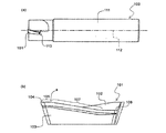
図16(a)は、特許文献1に記載されているような従来の切削工具を示す側面図であり、図16(b)は、図16(a)の切削工具に装着される従来の切削インサートを示す拡大側面図である。図16(a)に示すように、エンドミルである切削工具100は、切刃を有する切削インサート101と、この切削インサート101を取り付けるための切削インサートポケット110が先端部に設けられたホルダ111とで構成されている。そして、ホルダ111を該ホルダ111の軸心112を中心に回転させて、切削インサート101にて切削加工を行う。
16 (a) is a side view showing a conventional cutting tool as described in
ここで、切削インサート101は、図16(b)に示すように、上面102と側面103との稜線に切刃を有し、該切刃は、高位コーナ切刃104と、高位コーナ切刃104と略同一高さの平坦切刃105と、高位コーナ切刃104から低位コーナ部106に向かって漸次高さが低くなる傾斜切刃107とで構成されている。
しかしながら、このような構成の切削インサート101は、切削加工時において切削抵抗が大きい。そのため、切削加工時において振動が発生しやすく、切刃が欠損しやすいという問題がある。このような問題は、特に重切削加工において大きくなる。
Here, as shown in FIG. 16 (b), the
However, the
本発明の課題は、切削加工時における振動の発生と、切刃の欠損とを抑制することができる切削インサートおよびこれを用いる切削工具、並びに切削方法を提供することである。
本発明の他の課題は、切削抵抗が小さく、切削性能に優れる切削インサートおよびこれを用いる切削工具、並びに切削方法を提供することである。
The subject of this invention is providing the cutting insert which can suppress generation | occurrence | production of the vibration at the time of cutting, and the defect | deletion of a cutting blade, a cutting tool using the same, and a cutting method.
Another object of the present invention is to provide a cutting insert having a low cutting resistance and excellent cutting performance, a cutting tool using the same, and a cutting method.
本発明者は、上記課題を解決すべく鋭意検討を重ねた結果、以下の知見を得た。すなわち、切削インサート101が有する上記切刃のうち、ホルダ111の先端に位置する平坦切刃105は、常に切削加工に使用される高位コーナ切刃104の強度を保持するためのものである。前記平坦切刃105は、切削加工時に被削材が最初に接触するため強度が必要とされる。このため、前記平坦切刃105は、強度と切刃角度の維持とを両立させる上で、高位コーナ切刃104と略同一高さで形成される。
As a result of intensive studies to solve the above-mentioned problems, the present inventor has obtained the following knowledge. That is, among the cutting blades of the
一方、傾斜切刃107を設けると、切削インサート101自体に軸方向すくい角(アキシャルレーキ角)が付与されるので、ホルダ111への切削インサート101取付時に、ホルダ111を軸方向すくい角を大きく取らなくても、切削性を向上させ切削抵抗の低減を図ることができる。また、切削インサート101の底面下に位置するホルダ111の肉厚を確保することができ、ホルダ111の剛性を保つことができる。
On the other hand, when the
ところが、切刃をこのように構成すると、該切刃の途中で切刃の角度が変わる、すなわち平坦切刃105と傾斜切刃107との交点において、切刃の角度が変わる交点aを有することになる(図16(b)参照)。そして、この交点aには切削加工時に応力がかかり易く、該交点aを起点として切削加工時に振動が発生し、切刃の欠損が生じ易い。
However, when the cutting edge is configured in this way, the angle of the cutting edge changes in the middle of the cutting edge, that is, at the intersection of the
そこで、逃げ面103に特定の溝部を形成すると、切削抵抗を低減することができる。また、少なくとも1つの前記溝部を、平坦切刃105を延長した延長線と、傾斜切刃107を延長した延長線との交点を含む領域、すなわち前記切刃の角度が変わる交点aを含む領域に形成するか、または前記溝部を介して第1平坦切刃と傾斜切刃とを連続して形成すると、切削加工時に交点aに集中する応力を低減することができる。その結果、切削加工時における振動の発生と、切刃の欠損とを抑制することができる。
Therefore, if a specific groove is formed on the
すなわち、本発明の切削インサートは、上面と複数の側面とを有するインサート本体と、前記側面のうちの少なくとも1つの側面と前記上面との稜線の両端間に位置する切刃と、該高位部より前記インサート本体の厚み方向において低位でありかつ前記稜線の他端に位置する低位部とを備え、前記切刃は、前記高位部側と略同一高さの第1平坦切刃と、高位部から低位部に向かって高さが低くなる傾斜切刃とを備えており、前記少なくとも1つの側面には、該側面から前記上面に亘り前記切刃を分断する少なくとも1つの溝部が形成されており、該少なくとも1つの溝部は、前記第1平坦切刃を延長した第1延長線と、前記傾斜切刃を延長した第2延長線との交点を含む領域に形成されていることを特徴とする。 That is, the cutting insert of the present invention includes an insert main body having an upper surface and a plurality of side surfaces, a cutting blade positioned between both ends of a ridge line between at least one side surface of the side surfaces and the upper surface, and the high-order portion. A low level portion that is low in the thickness direction of the insert main body and located at the other end of the ridge line, and the cutting blade includes a first flat cutting blade that is substantially the same height as the high level portion side, and a high level portion. An inclined cutting edge having a height that decreases toward the lower portion, and at least one groove portion that divides the cutting blade from the side surface to the upper surface is formed on the at least one side surface, The at least one groove portion is formed in a region including an intersection of a first extension line extending from the first flat cutting edge and a second extension line extending from the inclined cutting edge.
本発明の切削インサートは、上面と複数の側面とを有するインサート本体と、前記側面のうちの少なくとも1つの側面と前記上面との稜線の両端間に位置する切刃と、前記稜線の一端に位置する高位部と、該高位部より前記インサート本体の厚み方向において低位でありかつ前記稜線の他端に位置する低位部とを備え、前記切刃は、前記高位部側と略同一高さの第1平坦切刃と、高位部から低位部に向かって高さが低くなる傾斜切刃とを備えており、前記少なくとも1つの側面には、該側面から前記上面に亘り前記切刃を分断する少なくとも1つの溝部が形成されており、前記1つの溝部を介して前記第1平坦切刃と前記傾斜切刃とが連続して形成されていることを特徴とする。 The cutting insert of the present invention includes an insert body having an upper surface and a plurality of side surfaces, a cutting blade positioned between both ends of the ridge line between at least one of the side surfaces and the upper surface, and one end of the ridge line. And a lower portion that is lower in the thickness direction of the insert body than the higher portion and located at the other end of the ridge line, and the cutting blade has a first height substantially the same as that of the higher portion. 1 a flat cutting edge and an inclined cutting edge whose height decreases from a high part to a low part, and the at least one side surface includes at least a part that cuts the cutting blade from the side surface to the top surface. One groove is formed, and the first flat cutting edge and the inclined cutting edge are continuously formed through the one groove.
また、本発明者は、上記他の課題を解決すべく鋭意研究を重ねた結果、以下の構成からなる解決手段を見出し、本発明を完成するに至った。
すなわち、本発明の他の切削インサートは、上面と複数の側面とを有するインサート本体と、前記側面のうちの少なくとも1つの側面と前記上面との稜線の両端間に位置する切刃と、前記稜線の一端に位置する高位部と、該高位部より前記インサート本体の厚み方向において低位でありかつ前記稜線の他端に位置する低位部とを備え、備え切刃は前記低位部側と略同一高さの後端溝部が形成されていると\ich前記切刃は、前記高位部側と略同一高さの第1平坦切刃と、高位部から低位部に向かって高さが低くなる傾斜切刃とを備えており、前記少なくとも1つの側面には、該側面から前記上面に亘り前記切刃を分断する少なくとも1つの溝部が形成されており、前記少なくとも1つの溝部は前記傾斜切刃にのみ形成されていることを特徴とする。
Further, as a result of intensive studies to solve the above-mentioned other problems, the present inventor has found a solution means having the following configuration, and has completed the present invention.
That is, another cutting insert of the present invention includes an insert body having an upper surface and a plurality of side surfaces, a cutting edge positioned between both ends of a ridge line between at least one of the side surfaces and the upper surface, and the ridge line. A high-order portion located at one end of the insert body, and a low-order portion that is lower in the thickness direction of the insert body than the high-order portion and located at the other end of the ridgeline, and the cutting blade is substantially the same height as the low-order portion side. When the rear end groove portion is formed, the cutting blade includes a first flat cutting blade having substantially the same height as the high-order portion side, and an inclined cutting edge whose height decreases from the high-order portion toward the low-order portion. And at least one groove portion that divides the cutting blade from the side surface to the upper surface is formed on the at least one side surface, and the at least one groove portion is formed only on the inclined cutting blade. It is characterized by being formed .
本発明の他の切削インサートは、上面と複数の側面とを有するインサート本体と、前記側面のうちの少なくとも1つの側面と前記上面との稜線の両端間に位置する切刃と、前記稜線の一端に位置する高位部と、該高位部より前記インサート本体の厚み方向において低位でありかつ前記稜線の他端に位置する低位部とを備え、前記切刃は、前記高位部側と略同一高さの第1平坦切刃と、前記低位部側と略同一高さの第2平坦切刃と、前記第1平坦切刃と第2平坦切刃との間に位置して高位部から低位部に向かって高さが低くなる傾斜切刃とを備えており、前記少なくとも1つの側面には、該側面から前記上面に亘り前記切刃を分断する少なくとも1つの溝部が形成されていると共に、前記溝部は、前記傾斜切刃または第2平坦切刃にのみ形成されていることを特徴とする。 Another cutting insert of the present invention includes an insert body having an upper surface and a plurality of side surfaces, a cutting blade positioned between both ends of the ridge line between at least one of the side surfaces and the upper surface, and one end of the ridge line. And a low-order part positioned lower than the high-order part in the thickness direction of the insert main body and at the other end of the ridgeline, and the cutting edge is substantially the same height as the high-order part side. The first flat cutting blade, the second flat cutting blade having substantially the same height as the low level portion, and the first flat cutting blade and the second flat cutting blade are positioned between the high level portion and the low level portion. And at least one groove portion that divides the cutting blade from the side surface to the upper surface is formed on the at least one side surface, and the groove portion. Is formed only on the inclined cutting edge or the second flat cutting edge. And wherein the are.
本発明の他の切削インサートは、上面と複数の側面とを有するインサート本体と、前記側面のうちの少なくとも1つの側面と前記上面との稜線の両端間に位置する切刃と、前記稜線の一端に位置する高位部と、該高位部より前記インサート本体の厚み方向において低位でありかつ前記稜線の他端に位置する低位部とを備え、前記切刃は、前記高位部側と略同一高さの第1平坦切刃と、前記低位部側と略同一高さの第2平坦切刃と、前記第1平坦切刃と第2平坦切刃との間に位置して高位部から低位部に向かって高さが低くなる傾斜切刃とを備えており、前記少なくとも1つの側面には、該側面から前記上面に亘り前記切刃を分断する複数の溝部が形成されており、前記複数の溝部のうち、最も高位部側に位置するものを先端溝部、最も低位部側に位置するものを後端溝部としたとき、前記高位部から前記先端溝部までの距離Aは、前記低位部から前記後端溝部までの距離Bよりも長いことを特徴とする。 Another cutting insert of the present invention includes an insert body having an upper surface and a plurality of side surfaces, a cutting blade positioned between both ends of the ridge line between at least one of the side surfaces and the upper surface, and one end of the ridge line. And a low-order part positioned lower than the high-order part in the thickness direction of the insert main body and at the other end of the ridgeline, and the cutting edge is substantially the same height as the high-order part side. The first flat cutting blade, the second flat cutting blade having substantially the same height as the low level portion, and the first flat cutting blade and the second flat cutting blade are positioned between the high level portion and the low level portion. A plurality of groove portions that divide the cutting blade from the side surface to the upper surface are formed on the at least one side surface, and the plurality of groove portions. Of these, the one located on the highest position side is the tip groove, the lowest position When the rear end groove those located a distance A from the higher portion to said tip groove is characterized by longer than the distance B from the lower portion to the rear end groove.
本発明の切削インサートによれば、前記側面には、該側面から上面に亘り切刃を分断する少なくも1つの溝部が形成されている。したがって、この溝部を形成した切削インサートを用いて切削加工を行うと、前記溝部に対応する位置の被削材は切削されないので、この切削しない分だけ切削抵抗を低減することができる。 According to the cutting insert of the present invention, at least one groove for dividing the cutting blade from the side surface to the upper surface is formed on the side surface. Therefore, when cutting is performed using the cutting insert in which the groove portion is formed, the work material at a position corresponding to the groove portion is not cut, so that the cutting resistance can be reduced by the amount not cut.
しかも、前記少なくとも1つの溝部は、第1平坦切刃を延長した第1延長線と、傾斜切刃を延長した第2延長線との交点(すなわち切刃の角度が変わる交点)を含む領域に形成されているので、切削加工時に前記交点に集中する応力を低減することができ、切削加工時における振動の発生と、切刃の欠損とを抑制することができる。 In addition, the at least one groove portion is in a region including an intersection (that is, an intersection where the angle of the cutting edge changes) between a first extension line extending the first flat cutting edge and a second extension line extending the inclined cutting edge. Since it is formed, the stress concentrated on the intersection at the time of cutting can be reduced, and the occurrence of vibrations at the time of cutting and chipping of the cutting edge can be suppressed.
また、前記溝部を介して、平坦切刃と傾斜切刃とが連続して形成されているので、前記と同様に、切削加工時における振動の発生と、切刃の欠損とを抑制することができる。 Further, since the flat cutting edge and the inclined cutting edge are continuously formed via the groove portion, similarly to the above, it is possible to suppress the generation of vibrations during cutting and chipping of the cutting edge. it can.
本発明の他の切削インサートによれば、前記側面には、該側面から上面に亘り切刃を分断する少なくとも1つの溝部が形成されている。したがって、前記した本発明の切削インサートと同様に、溝部に対応する位置の被削材は切削されないので、この切削しない分だけ切削抵抗を低減することができる。 According to another cutting insert of the present invention, the side surface is formed with at least one groove portion that divides the cutting blade from the side surface to the upper surface. Therefore, similarly to the cutting insert of the present invention described above, the work material at the position corresponding to the groove is not cut, so that the cutting resistance can be reduced by the amount not cut.
しかも、前記溝部を前記傾斜切刃にのみ形成するので、切刃強度を保持しつつ切削抵抗を低減することができる。すなわち切削インサートが有する切刃のうち、前記第1平坦切刃は、常に切削加工に使用される高位部の強度を保持するためのものであり、切削加工時に被削材が最初に接触するため強度が必要とされる。 And since the said groove part is formed only in the said inclined cutting blade, cutting resistance can be reduced, maintaining cutting blade strength. That is, among the cutting blades of the cutting insert, the first flat cutting blade is for always maintaining the strength of the high-order portion used for cutting work, and the work material first comes into contact with the cutting work. Strength is required.
一方、傾斜切刃を設けると、切削インサート自体に軸方向すくい角(アキシャルレーキ角)が付与されるので、工具ホルダへの切削インサート取付時に、工具ホルダを減肉して軸方向すくい角を大きく取らなくても切削性能を向上することができる。本発明の他の切削インサートによれば、この傾斜切刃にのみ前記溝部を形成するので、第1平坦切刃に溝部を形成することによる第1平坦切刃の強度低下がなく、常に切削加工に使用される高位部の強度を保持することができる。したがって、切刃強度を保持しつつ切削抵抗を低減することができ、優れた切削性能を示すことができる。 On the other hand, when an inclined cutting edge is provided, an axial rake angle (axial rake angle) is given to the cutting insert itself, so that when the cutting insert is attached to the tool holder, the tool holder is thinned to increase the axial rake angle. Cutting performance can be improved without taking. According to another cutting insert of the present invention, since the groove is formed only on the inclined cutting edge, there is no reduction in strength of the first flat cutting edge due to the formation of the groove on the first flat cutting edge. It is possible to maintain the strength of the high-order portion used in the above. Therefore, cutting resistance can be reduced while maintaining the cutting edge strength, and excellent cutting performance can be exhibited.
また、前記溝部を、前記傾斜切刃または第2平坦切刃にのみ形成するので、第1平坦切刃に溝部を形成することによる第1平坦切刃の強度低下がなく、切刃強度を保持しつつ切削抵抗を低減することができ、優れた切削性能を示すことができる。しかも、切刃が第2平坦切刃を備えるので、切削性能をより向上させることができる。 Further, since the groove is formed only on the inclined cutting edge or the second flat cutting edge, the strength of the first flat cutting edge is not reduced by forming the groove on the first flat cutting edge, and the cutting edge strength is maintained. However, the cutting resistance can be reduced and excellent cutting performance can be exhibited. Moreover, since the cutting edge includes the second flat cutting edge, the cutting performance can be further improved.
前記溝部のうち、最も高位部側に位置するものを先端溝部とし、最も低位部側に位置するものを後端溝部としたとき、前記高位部から先端溝部までの距離Aを、低位部から後端溝部までの距離Bよりも長く構成するので、高位部の強度を十分に保持することができる。その結果、切刃強度を保持しつつ切削抵抗を低減することができ、優れた切削性能を示すことができる。しかも、切刃が第2平坦切刃を備えるので、切削性能をより向上させることができる。 When the groove located on the highest position side among the grooves is the leading groove and the groove located on the lowest position is the trailing groove, the distance A from the high position to the leading groove is determined from the low position to the rear. Since it is configured to be longer than the distance B to the end groove portion, the strength of the high-order portion can be sufficiently maintained. As a result, cutting resistance can be reduced while maintaining cutting edge strength, and excellent cutting performance can be exhibited. Moreover, since the cutting edge includes the second flat cutting edge, the cutting performance can be further improved.
<切削インサート>
(第1の実施形態)
以下、本発明にかかる切削インサートの第1の実施形態について図面を参照して詳細に説明する。
<Cutting insert>
(First embodiment)
Hereinafter, a first embodiment of a cutting insert according to the present invention will be described in detail with reference to the drawings.
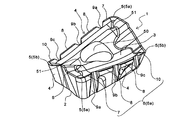
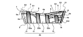
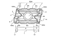
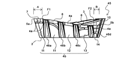
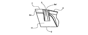
図1〜図3に示すように、本実施形態にかかる切削インサート(以下、インサートと略す。)1は、上面視で略平行四辺形のインサート本体を有しており、着座面をなす底面2と、すくい面を有する上面3と、逃げ面を有する側面4とを備えている。さらに、上面3と側面4との稜線のうち前記インサート本体の角部に位置するコーナ部5(5a,5b)と、前記稜線のうち2つのコーナ部5,5の間(すなわち前記稜線の両端間)に位置し、前記2つのコーナ部5,5とつながる切刃6とを備えている。
As shown in FIGS. 1 to 3, a cutting insert (hereinafter abbreviated as an insert) 1 according to the present embodiment has a substantially parallelogram-shaped insert body in a top view, and a
上面3が有する前記すくい面とは、上面3のうち生成した切り屑が擦過する面のことを意味する。上面3の中央部には、底面2まで貫通した貫通穴50が形成されている。この貫通穴50は、インサート1を後述する図12,図13に示す工具ホルダ(以下、ホルダと略す。)60に固定するためのものである。インサート1は、該貫通穴50の中心軸に対して180度回転対称な形状であり、これにより使用している一方の切刃が摩耗した際には、インサート1を180度回転させ、使用していない他方の切刃を用いることができるので使い勝手がよい。
The rake face of the
上面3の長手方向には、下記で説明する高位コーナ切刃5aおよび切刃6から中央に向かうにつれて一旦低くなった後に隆起する隆起部51を有するようにチップブレーカが形成されている(図1参照)。これにより、切屑がカールされるか、分断されるので、生成する切屑を良好に排出することができる。
In the longitudinal direction of the
コーナ部5は、一方の対角線上に位置する2つの高位コーナ切刃5a,5a(高位部)と、該高位コーナ切刃5aよりインサート本体の厚み方向において低位でありかつ他方の対角線上に位置する2つの低位コーナ部5b,5b(低位部)とを備えている。高位コーナ切刃5aは、常に切削加工に使用される切刃であり、その曲率半径は、切刃強度と加工形状とのバランスから、通常、0.4〜6.4mm程度であるのが好ましい。
The
切刃6のうち、インサート1の長手方向に位置する主切刃6aは、高位コーナ切刃5a側と略同一高さの第1平坦切刃7と、高位コーナ切刃5aから低位コーナ部5bに向かって漸次高さが低くなる傾斜切刃8とを備えている。第1平坦切刃7は、常に切削加工に使用される高位コーナ切刃5aの強度を保持するためのものであり、切削加工時に被削材が最初に接触するため強度が必要とされ、強度と切刃角度の維持とを両立させる上で、高位コーナ切刃5aと略同一高さで形成される。
Among the
また、傾斜切刃8を設けることにより、インサート1自体に軸方向すくい角(アキシャルレーキ角)が付与されるので、ホルダ60へのインサート1取付時に、ホルダ60を減肉して軸方向すくい角を大きく取らなくても、切削性を向上させ切削抵抗の低減を図ることができる。さらに、前記理由から、ホルダ60にインサート1が取付けられた状態での軸方向すくい角を最小限にすることができるので、インサート1の底面2下に位置するホルダ60の肉厚を確保することができ、ホルダ60の剛性を保つことができる。
Further, by providing the
ここで、インサート1の各長手方向における側面4には、該側面4から上面3に亘り主切刃6aを分断する複数の溝部(ニック)として、溝部9a,9b,9cがそれぞれ形成されている。これにより、切削加工時における切削抵抗を低減することができる。すなわち、このインサート1を用いて切削加工を行うと、溝部9a,9b,9cに対応する位置の被削材は切削されないので、この切削しない分だけ切削抵抗を低減することができる。なお、未切削部分については、例えば後述するホルダ60におけるインサート1の取付位置を調整するか、インサート1と、図4,図5に示すような溝部の個数が4つのインサート21とを組み合わせる等して切削加工を行えばよい。
Here, on the side surface 4 in each longitudinal direction of the
そして、図3に示すように、溝部9a,9b,9cうち溝部9aが、第1平坦切刃7を延長した第1延長線S1と、傾斜切刃8を延長した第2延長線S2との交点aを含む領域に形成されている。また、該溝部9aを介して、第1平坦切刃7と傾斜切刃8とが連続して形成されている。これにより、切削加工時に交点aに集中する応力を低減することができ、切削加工時における振動の発生と、切刃の欠損とを抑制することができる。これに対し、溝部9aが交点aを含む領域に形成されていないか、または溝部9aを介して第1平坦切刃7と傾斜切刃8とが連続して形成されていない場合には、切削加工時に振動が発生して切刃が欠損する。
And as shown in FIG. 3, the
特に、本実施形態では、交点aを含む領域に形成された溝部9aは、主切刃6aに形成された複数の溝部9a,9b,9cのうち、最も高位コーナ切刃5a側に位置する。これにより、切削加工時に被削材が最初に接触するため大きな応力がかかる第1平坦切刃7の強度を保つことができる。これに対し、溝部9aよりも高位コーナ切刃5a側にさらに溝部を設けると、第1平坦切刃7の厚みが減るため強度が低下し、切刃が欠損するおそれがある。
In particular, in this embodiment, the
溝部9a,9b,9cは、上面3から下面2に向かって漸次幅が広くなるように形成されている。これにより、主切刃6aの減肉による強度低下を抑制し、該主切刃6aの強度を保持することができる。なお、少なくとも最も高位コーナ部5a側に位置する溝部9aが当該構成を備えていることにより、常に切削加工に使用される高位コーナ切刃5aの強度を保持することができる。
The
主切刃6aは、低位コーナ部5b側と略同一高さの第2平坦切刃10を備えている。これにより、切削性が向上する。また、主切刃6aの後端部において厚み減少によるインサート1の強度低下を抑制することができ、側面4のホルダ60への拘束面積を確保することができる。
The
さらに、傾斜切刃8は第1平坦切刃7と第2平坦切刃10との間に位置し、溝部9cが、傾斜切刃6aを延長した第2延長線S2と、第2平坦切刃10を延長した第3延長線S3との交点bを含む領域に形成されている。これにより、前記交点aで説明したのと同様に、切削加工時に交点bに集中する応力を低減することができ、切削加工時における振動の発生と、切刃の欠損とを抑制することができる。
Further, the
インサート1の長手方向における側面4は、主切刃6a側に形成され高位コーナ切刃5aから低位コーナ部5bに向かって漸次逃げ角が大きくなる切刃側逃げ面4aを備えている(図3参照)。これにより、軸方向すくい角(アキシャルレーキ角)が付加されるか、または刃先が芯高(半径方向すくい角(ラジアルレーキ角)が負角)となるようにホルダ60にインサート1が装着されるような状態においても、インサート1がホルダ60に取り付けられた状態における逃げ角(実逃げ角)が過大になることなく適正角度で維持されることから、切刃強度を確保することが可能である。
The side surface 4 in the longitudinal direction of the
インサート1の長手方向における側面4のうち、切刃側逃げ面4aから底面2に亘る側面4bは、第1平坦切刃7の前記インサート本体の厚み方向における低位側の領域に第1逃げ面11、傾斜切刃8の前記低位側領域に第2逃げ面12、第2平坦切刃10の前記低位側領域に第3逃げ面13をそれぞれ有している。そして、第1逃げ面11および第3逃げ面13は、略同一平面上に位置する拘束面を備えている。すなわち、第1逃げ面11および第3逃げ面13が略同一の逃げ角で構成されている。これにより、インサート1をホルダ60に取り付けた際には、第1逃げ面11および第3逃げ面13がホルダ60に接するための安定面、すなわち拘束面となるので、ホルダ60への拘束力が高まり、切削加工時の振動の発生をより抑制することができる。なお、本実施形態では、第2逃げ面12が、第1逃げ面11および第3逃げ面13から突出するように構成されているが、本発明はこれに限定されるものではなく、第1逃げ面11、第2逃げ面12および第3逃げ面13が、それぞれ略同一の逃げ角で構成されていてもよい。
Of the side surfaces 4 in the longitudinal direction of the
第3逃げ面13には、高位コーナ切刃5aから低位コーナ部5bに向かって漸次幅が広くなる平面部14が設けられている(図3参照)。これにより、インサート1に正の軸方向すくい角を付してホルダ60へ取り付けた際には、インサート1の底面2側の角部と被削材との干渉を抑制することができる。
The
(第2の実施形態)
次に、第2の実施形態について図面を参照して詳細に説明する。なお、参照する図4,図5においては、前述した図1〜図3と同一の構成部分には同一の符号を付して説明は省略する。
(Second Embodiment)
Next, a second embodiment will be described in detail with reference to the drawings. 4 and 5 to be referred to, the same components as those shown in FIGS.
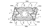
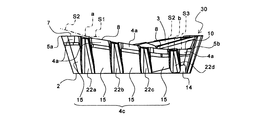
本実施形態のインサートは、形成される溝部の個数が4つである点で、溝部の個数が3つである第1の実施形態にかかるインサート1と異なる。すなわち、図4,図5に示すように、本実施形態にかかるインサート21は、各長手方向おける側面4において、該側面4から上面3に亘り主切刃6aを分断する複数の溝部として、溝部22a,22b,22c,22dがそれぞれ形成されている。したがって、上記インサート1よりも溝部の個数が多いので、切削加工時における切削抵抗をより低減することができる。
The insert of this embodiment is different from the
そして、溝部22a〜22dうち溝部22aが、第1平坦切刃7を延長した第1延長線S1と、傾斜切刃8を延長した第2延長線S2との交点aを含む領域に形成されており、溝部22aを介して、第1平坦切刃7と傾斜切刃8とが連続して形成されている。したがって、溝部を4つ設ける本実施形態のような構成であっても、上記で説明した第1の実施形態と同様に、切削加工時に交点aに集中する応力を低減することができ、切削加工時における振動の発生と、切刃の欠損とを抑制することができる。
Of the
また、本実施形態においても、溝部22dが、傾斜切刃8を延長した第2延長線S2と、第2平坦切刃10を延長した第3延長線S3との交点bを含む領域に形成されている。これにより、上記で説明した第1の実施形態と同様に、切削加工時に交点bに集中する応力を低減することができる。
Also in the present embodiment, the
溝部22a〜22dは、上面3から下面2に向かって漸次幅が広くなるように形成されている。これにより、主切刃6aの強度を保持することができる。
なお、上記した以外の構成は、上記で説明した第1の実施形態と同様であるので、説明は省略する。
The
Since the configuration other than the above is the same as that of the first embodiment described above, description thereof will be omitted.
(第3の実施形態)
次に、第3の実施形態について図面を参照して詳細に説明する。なお、参照する図6においては、前述した図1〜図5と同一の構成部分には同一の符号を付して説明は省略する。
(Third embodiment)
Next, a third embodiment will be described in detail with reference to the drawings. In FIG. 6 to be referred to, the same components as those in FIGS.
本実施形態のインサートは、切刃側逃げ面4aから底面2に亘る側面において、第1逃げ面11、第2逃げ面12および第3逃げ面13が形成されていない点で、これらの逃げ面が形成されている上記で説明した第2の実施形態にかかるインサート21と異なる。すなわち、図6に示すように、本実施形態にかかるインサート30は、切刃側逃げ面4aから底面2に亘る側面4cが、高位コーナ切刃5aから低位コーナ部5bに向かって漸次逃げ角が変化する逃げ面15で構成されている。これにより、側面4cを加工する際の工程が簡略化されるので、コストダウンを図ることができる。
The insert according to this embodiment is such that the
そして、溝部22a〜22dうち溝部22aが、前記交点aを含む領域に形成されており、溝部22aを介して、第1平坦切刃7と傾斜切刃8とが連続して形成されている。したがって、本実施形態のような構成であっても、上記で説明した第1,第2の実施形態と同様に、切削加工時に交点aに集中する応力を低減することができ、切削加工時における振動の発生と、切刃の欠損とを抑制することができる。
なお、上記した以外の構成は、上記で説明した第1,第2の実施形態と同様であるので、説明は省略する。
And the
Since the configuration other than the above is the same as that of the first and second embodiments described above, description thereof will be omitted.
(第4の実施形態)
次に、第4の実施形態について図面を参照して詳細に説明する。なお、参照する図7,図8においては、前述した図1〜図6と同一の構成部分には同一の符号を付して説明は省略する。
(Fourth embodiment)
Next, a fourth embodiment will be described in detail with reference to the drawings. In FIGS. 7 and 8 to be referred to, the same components as those in FIGS.
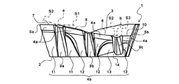
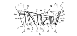
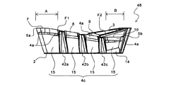
図7,図8に示すように、本実施形態にかかるインサート41は、長手方向の側面4において、該側面4から上面3に亘り主切刃6aを分断する複数の溝部として、溝部42a,42b,43cがそれぞれ形成されている。これにより、切削加工時における切削抵抗を低減することができる。
As shown in FIGS. 7 and 8, the
そして、溝部42a,42b,43cが、傾斜切刃8および第2平坦切刃10にのみ形成されている(図7参照)。これにより、第1平坦切刃7に溝部を形成することによる第1平坦切刃7の強度低下がなく、高位コーナ切刃5aの強度を保持することができ、その結果、切刃強度を保持しつつ切削抵抗を低減することができる。
And groove
さらに図8に示すように、本実施形態では溝部42a,42b,42cのうち、最も高位コーナ切刃5a側に位置する溝部42aを先端溝部とし、最も低位コーナ部5b側に位置する溝部42cを後端溝部としたとき、高位コーナ切刃5aから先端溝部(42a)までの距離Aは、低位コーナ部5bから後端溝部(42c)までの距離Bよりも長く構成されている。これにより、高位コーナ切刃5aの強度を十分に保持することができ、切刃強度を保持しつつ切削抵抗を低減することができ、優れた切削性能を示すことができる。
Further, as shown in FIG. 8, in the present embodiment, of the
一方、前記距離A,Bが前記所定の関係に構成されていないと、高位コーナ切刃5aの強度が低下して切刃が欠損しやすくなる。
前記距離Aとは、高位コーナ切刃5aから、溝部42aにおける最も高位コーナ切刃5a側に位置する縁部F1までの距離のことを意味する。前記距離Bとは、低位コーナ部5bから、溝部42cにおける最も低位コーナ部5b側に位置する縁部F2までの距離を意味する。
On the other hand, if the distances A and B are not configured in the predetermined relationship, the strength of the high-order
The distance A means the distance from the high-order
また図7に示すように、主切刃6aの長さをLとし、第1平坦切刃7の長さをL1としたとき、L:L1=1:0.15〜0.30、好ましくは1:0.15であるのがよい。これにより、第1平坦切刃7が十分な強度を有するので、高位コーナ切刃5aの強度を確実に保持することができる。
7, when the length of the
第1平坦切刃7は、第2平坦切刃10よりも短く形成されているのが好ましい。これにより、切削加工時において第1平坦切刃7にかかる負荷を低減することができ、切削抵抗をより低減することができる。具体的には、図7に示すように、第1平坦切刃7の長さをL1とし、第2平坦切刃10の長さをL2としたとき、L1:L2=1:2〜4、好ましくは1:2であるのがよい。これにより、切削抵抗をさらに低減することができる。
The first
溝部42a,42b,42cは、上面3から下面2に向かって漸次幅が広くなるように形成されている。これにより、主切刃6aの強度を保持することができる。
本実施形態では、主切刃6aが第2平坦切刃10を備えているが、用途に応じて主切刃が第2平坦切刃10を備えていなくてもよい。この場合には、複数の溝部である溝部42a,42b,42cは、傾斜切刃8にのみ形成されていればよく、これにより上記で説明した場合と同様の効果を奏することができる。
なお、上記した以外の構成は、上記で説明した第1〜第3の実施形態と同様であるので、説明は省略する。
The
In the present embodiment, the
Since the configuration other than the above is the same as that of the first to third embodiments described above, description thereof will be omitted.
(第5の実施形態)
次に、第5の実施形態について図面を参照して詳細に説明する。なお、参照する図9,図10においては、前述した図1〜図8と同一の構成部分には同一の符号を付して説明は省略する。
(Fifth embodiment)
Next, a fifth embodiment will be described in detail with reference to the drawings. In FIGS. 9 and 10 to be referred to, the same components as those in FIGS.
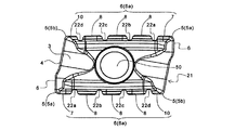
本実施形態のインサートは、形成される溝部の個数が4つである点で、溝部の個数が3つである上記で説明した第4の実施形態にかかるインサート41と異なる。すなわち、図9,図10に示すように、本実施形態にかかるインサート45は、長手方向の側面4において、該側面4から上面3に亘り主切刃6aを分断する複数の溝部として、溝部46a,46b,46c,46dがそれぞれ形成されている。したがって、上記インサート41よりも溝部の個数が多いので、切削加工時における切削抵抗をより低減することができる。
The insert of this embodiment is different from the
そして、溝部46a〜46dは、上記で説明した第4の実施形態と同様に、傾斜切刃8および第2平坦切刃10にのみ形成されている。したがって、溝部を4つ設ける本実施形態のような構成であっても、第4の実施形態と同様に、第1平坦切刃7に溝部を形成することによる第1平坦切刃7の強度低下がなく、高位コーナ切刃5aの強度を保持することができ、その結果、切刃強度を保持しつつ切削抵抗を低減することができる。特に、本実施形態によれば、溝部の個数が多い分、第4の実施形態よりも切削加工時における切削抵抗をより低減することができる。
And the
さらに本実施形態では、溝部46a〜46dのうち、最も高位コーナ切刃5a側に位置する溝部46aを先端溝部とし、最も低位コーナ部5b側に位置する溝部46dを後端溝部としたとき、高位コーナ切刃5aから先端溝部(46a)までの距離Aは、低位コーナ部5bから後端溝部(46d)までの距離Bよりも長く構成されている。したがって、第4の実施形態と同様に、高位コーナ切刃5aの強度を十分に保持することができ、切刃強度を保持しつつ切削抵抗を低減することができ、優れた切削性能を示すことができる。
Furthermore, in this embodiment, when the
溝部46a〜46dは、上面3から下面2に向かって漸次幅が広くなるように形成されている。これにより、主切刃6aの強度を保持することができる。
なお、上記した以外の構成は、上記で説明した第1〜第4の実施形態と同様であるので、説明は省略する。
The
Since the configuration other than the above is the same as that of the first to fourth embodiments described above, the description thereof will be omitted.
(第6の実施形態)
次に、第6の実施形態について図面を参照して詳細に説明する。なお、参照する図11においては、前述した図1〜図10と同一の構成部分には同一の符号を付して説明は省略する。
(Sixth embodiment)
Next, a sixth embodiment will be described in detail with reference to the drawings. In FIG. 11 to be referred to, the same components as those in FIGS.
本実施形態のインサートは、切刃側逃げ面4aから底面2に亘る側面において、第1逃げ面11、第2逃げ面12および第3逃げ面13が形成されていない点で、これらの逃げ面が形成されている上記で説明した第4の実施形態にかかるインサート41と異なる。すなわち、図11に示すように、本実施形態にかかるインサート48は、切刃側逃げ面4aから底面2に亘る側面4cが、高位コーナ切刃5aから低位コーナ部5bに向かって漸次逃げ角が変化する逃げ面15で構成されている。これにより、側面4cを加工する際の工程が簡略化されるので、コストダウンを図ることができる。
The insert according to this embodiment is such that the
そして、溝部42a〜42cは、上記で説明した第4の実施形態と同様に、傾斜切刃8および第2平坦切刃10にのみ形成されている。したがって、本実施形態のような構成であっても、第1平坦切刃7に溝部を形成することによる第1平坦切刃7の強度低下がなく、高位コーナ切刃5aの強度を保持することができ、その結果、切刃強度を保持しつつ切削抵抗を低減することができる。
なお、上記した以外の構成は、上記で説明した第1〜第5の実施形態と同様であるので、説明は省略する。
And the
In addition, since structures other than those described above are the same as those in the first to fifth embodiments described above, description thereof will be omitted.
<切削工具・切削方法>
次に、本発明にかかる切削工具および切削方法の一実施形態について図面を参照して詳細に説明する。なお、参照する図12においては、前述した図1〜図11と同一の構成部分には同一の符号を付して説明は省略する。
<Cutting tools and cutting methods>
Next, an embodiment of a cutting tool and a cutting method according to the present invention will be described in detail with reference to the drawings. Note that, in FIG. 12 to be referred to, the same components as those in FIGS.
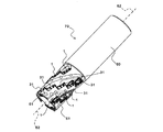
図12に示すように、本実施形態にかかる切削工具70は、溝部の個数が3つである第1の実施形態にかかるインサート1と、溝部の個数が2つである以外はインサート1と同様に構成されたインサート31と、先端外周側に複数のインサート1,31を着脱自在に取り付けるための切削インサートポケット(以下、ポケットと略す。)61を複数設けた略円筒状のホルダ60とを備えたエンドミルである。そして、ホルダ60を該ホルダ60の軸心62を中心に回転させて、インサート1,31にて切削加工を行う。
As shown in FIG. 12, the cutting
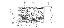
具体的には、図13に示すように、ホルダ60の先端外周側に設けられているポケット61は、ホルダ60の周方向に所定の間隔で、かつホルダ60の軸心62方向に複数列で設けられている。そして、上記で説明したインサート1の貫通穴50に締付けネジを挿通し、該締付けネジの先端側をポケット61の座面に形成されたネジ穴63に螺合することにより、複数のインサート1を軸心62方向に設けられた各ポケット61に着脱自在に取り付ける。
Specifically, as shown in FIG. 13, the
インサート1の側面4bにおける第1逃げ面11,第3逃げ面13は略同一平面上に位置する拘束面を備えているので、第1逃げ面11,第3逃げ面13に当接するポケット61の横当接面64,65も略同一平面で構成することができる。したがって、ポケット61を高い精度で加工することができるので、インサート1を高い取付精度と、高い拘束力とで取り付けることができ、切削加工時の振動の発生をより抑制することができる。
Since the
また、インサート1の側面4bにおける第2逃げ面12は、ポケット61の横当接面64,65の間に形成された切欠き部66に収納され、インサート1の切刃側逃げ面4aは、ポケット61の横当接面64,65の上部に形成された逃がし部67に収納される。これにより、インサート1をポケット61に取り付けた際には、切削に関与しない一方の主切刃6aは、ホルダ60に接触しない状態になる。
Further, the
ここで、インサート1は、切削工具70を回転させて被削材に接触させる時に、第1平坦切刃7が最初に被削材と接触するようにホルダ60に取り付けられている。このような特定の配置でインサート1がホルダ60に取り付けられることによって、インサート1が有する前記した効果を発揮させることが可能になる。
Here, the
一方、インサート31は、インサート1で切削加工を行った際に生じる未切削部分(すなわち溝部9a,9b,9cに対応する位置)にインサート31の切刃が位置するように取り付けられる以外は、インサート1と同様にして、複数のインサート31を軸心62方向に設けられた各ポケット61に着脱自在に取り付けられる。
On the other hand, the
このようにしてインサート1,31を各ポケット61に取り付けることにより、図12に示す構成の切削工具70とすることができる。この切削工具70は、溝部の個数が異なるインサート1,31を組み合わせた構成となっているので、切削加工を効率よく行うことができる。すなわち、溝部の個数が3つであるインサート1は、溝部の個数が2つであるインサート31よりも切削抵抗は低いが、未切削部分がインサート31よりも多く生じる。この未切削部分をインサート31が切削するので、切削抵抗を低減させながら効率よく切削加工を行うことができる。
By attaching the
上記した切削工具70を用いて切削加工を行うには、ホルダ60を該ホルダ60の軸心62を中心に回転させた状態で、インサート1,31の切刃を被削材(切削加工される金属ワーク等)の側面に当接させながら、ホルダ60を被削材に対して側面方向または深さ方向へ送ることによって所望の形状に被削材を切削加工することができる。
In order to perform cutting using the above-described
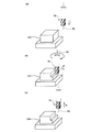
具体的には、この切削工具70を用いる被削材の切削方法は、近接工程、切削工程および離間工程を備える。すなわち近接工程では、図14(a)に示すように、被削材120に切削工具70を相対的に近づける(図14(a)中の矢印i方向)。切削工程では、図14(b)に示すように、切削工具70を回転させ、切削工具70の切刃を被削材120の表面に接触させて、切削工具70を矢印ii方向に送りながら被削材120を切削する。離間工程では、図14(c)に示すように、被削材120と切削工具70とを相対的に遠ざける(図14(c)中の矢印iii方向)。
Specifically, the cutting method of the work material using this
ここで、インサート1,31は、本発明にかかる複数の溝部が形成されているので、切削抵抗をより低減することができる。また、前記複数の溝部のうちの1つの溝部が、第1平坦切刃7を延長した第1延長線S1と、傾斜切刃8を延長した第2延長線S2との交点aを含む領域に形成されており、1つの前記溝部を介して第1平坦切刃7と傾斜切刃8とが連続して形成されているので、切削加工時に交点aに集中する応力を低減することができ、切削加工時における振動の発生と、切刃の欠損とを抑制することができる。したがって、切削工具70は、切削加工時における振動の発生を抑制しつつ、長期に亘り優れた切削性能を発揮することができる。
Here, since the
なお、前記近接工程において、切刃と被削材120とは相対的に近づけばよく、例えば被削材120を切削工具70に近づけてもよい。これと同様に、前記離間工程において、被削材120と切削工具70とは相対的に遠ざかればよく、例えば被削材120を切削工具70から遠ざけてもよい。切削加工を継続する場合には、切削工具70を回転させた状態を保持して、被削材120の異なる箇所に切削工具70の切刃を接触させる工程を繰り返せばよい。使用している切刃が摩耗した際には、インサート1,31を貫通穴50の中心軸に対して180度回転させ、使用していない切刃を用いればよい。
In the proximity step, the cutting edge and the
次に、本発明にかかる切削工具の他の実施形態について説明する。本実施形態にかかる切削工具は、インサート1に代えて溝部の個数が3つである第4の実施形態にかかるインサート41を、インサート31に代えて溝部の個数が2つである以外はインサート41と同様に構成されたインサートをそれぞれ用いた以外は、前記した切削工具70と同様に構成されている。
Next, another embodiment of the cutting tool according to the present invention will be described. The cutting tool according to the present embodiment is different from the
これらのインサートは、傾斜切刃8,第2平坦切刃10にのみ所定の複数の溝部が形成されている。また、インサートは、高位コーナ切刃5aから先端溝部までの距離Aが、低位コーナ部5bから後端溝部までの距離Bよりも長く構成されているので、切刃強度を保持しつつ切削抵抗を低減することができ、優れた切削性能を示すことができる。したがって、本実施形態にかかる切削工具は、切削加工時における切削抵抗が小さく、長期に亘り優れた切削性能を発揮することができる。
なお、上記した以外の構成は、上記で説明した一実施形態と同様であるので、説明は省略する。
In these inserts, a plurality of predetermined grooves are formed only in the
Since the configuration other than the above is the same as that of the embodiment described above, the description thereof will be omitted.
以上、本発明にかかるいくつかの実施形態について示したが、本発明は上述した実施形態に限定されるものではなく、本発明の要旨を逸脱しない範囲で変更や改良したものにも適用できることは言うまでもない。例えば前記した各実施形態では、溝部の個数が2〜4つのインサートについて説明したが、本発明にかかる溝部の個数はこれに限定されるものではなく、インサートの強度を低下させず、かつ切削抵抗を低減する上で、通常、1〜6つ程度、好ましくは2〜4つの範囲で任意に選定すればよい。この範囲内で、所定の溝部を複数形成すると、切削抵抗をより低減することができる。 As mentioned above, although some embodiment concerning this invention was shown, this invention is not limited to embodiment mentioned above, It can apply also to what was changed and improved in the range which does not deviate from the summary of this invention. Needless to say. For example, in each of the above-described embodiments, the insert having two to four grooves has been described. However, the number of the grooves according to the present invention is not limited to this, and the strength of the insert is not reduced and the cutting resistance is reduced. In general, it may be arbitrarily selected in the range of about 1 to 6, preferably 2 to 4. If a plurality of predetermined groove portions are formed within this range, cutting resistance can be further reduced.
また、前記した各実施形態にかかる溝部は略同形状で構成され、インサートの長手方向に略等間隔で形成されているが、用途に応じて溝部の形状や形成する間隔を異ならせてもよい。具体例を挙げると、前記した第1の実施形態にかかるインサート1では、溝部9a,9b,9cのうち溝部9a,9bは、上面3から底面2に亘り形成されているが、本発明にかかる溝部は、側面4から上面3に亘り主切刃6aを分断するような形状であればよい。したがって、溝部9aを例えば図15に示す溝部9a’のような形状に構成してもよい。
Moreover, although the groove part concerning each above-mentioned embodiment is comprised by substantially the same shape, and is formed in the longitudinal direction of insert at substantially equal intervals, you may vary the shape of a groove part and the space | interval to form according to a use. . As a specific example, in the
前記した各実施形態では、上面視が略平行四辺形のインサートについて説明したが、本発明にかかるインサートの形状はこれに限定されるものではなく、例えば略三角形状、略五角形状等の多角形であってもよい。インサートのホルダへの取り付けは、インサートをホルダのポケットにネジ止めするクランプ方式について説明したが、例えばクランプオン方式、レバーロック方式等を採用してもよい。 In each of the embodiments described above, the insert having a substantially parallelogram in the top view has been described. However, the shape of the insert according to the present invention is not limited to this, and for example, a polygon such as a substantially triangular shape or a substantially pentagonal shape. It may be. The attachment of the insert to the holder has been described with respect to the clamp method in which the insert is screwed into the pocket of the holder. However, for example, a clamp-on method, a lever lock method, or the like may be employed.
前記した切削工具70では、溝部の個数が異なるインサートを組み合わせて構成した場合について説明したが、本発明はこれに限定されるものではなく、溝部の個数が同一のインサートで切削工具を構成してもよい。
In the
Claims (12)
前記側面のうちの少なくとも1つの側面と前記上面との稜線の両端間に位置する切刃と、
前記稜線の一端に位置する高位部と、
該高位部より前記インサート本体の厚み方向において低位でありかつ前記稜線の他端に位置する低位部とを備え、
前記切刃は、前記高位部側と略同一高さの第1平坦切刃と、高位部から低位部に向かって高さが低くなる傾斜切刃とを備えており、
前記少なくとも1つの側面には、該側面から前記上面に亘り前記切刃を分断する少なくとも1つの溝部が形成されており、
前記少なくとも1つの溝部は前記傾斜切刃にのみ形成されていることを特徴とする切削インサート。 An insert body having an upper surface and a plurality of side surfaces;
A cutting blade located between both ends of the ridge line between at least one of the side surfaces and the upper surface;
A high-order part located at one end of the ridgeline;
A lower portion that is lower than the higher portion in the thickness direction of the insert body and is located at the other end of the ridgeline,
The cutting edge includes a first flat cutting edge having substantially the same height as the high-order part side, and an inclined cutting edge whose height decreases from the high-order part toward the low-order part,
The at least one side surface is formed with at least one groove portion that divides the cutting blade from the side surface to the upper surface,
The cutting insert according to claim 1, wherein the at least one groove is formed only on the inclined cutting edge.
前記側面のうちの少なくとも1つの側面と前記上面との稜線の両端間に位置する切刃と、
前記稜線の一端に位置する高位部と、
該高位部より前記インサート本体の厚み方向において低位でありかつ前記稜線の他端に位置する低位部とを備え、
前記切刃は、前記高位部側と略同一高さの第1平坦切刃と、前記低位部側と略同一高さの第2平坦切刃と、前記第1平坦切刃と第2平坦切刃との間に位置して高位部から低位部に向かって高さが低くなる傾斜切刃とを備えており、
前記少なくとも1つの側面には、該側面から前記上面に亘り前記切刃を分断する少なくとも1つの溝部が形成されていると共に、前記溝部は、前記傾斜切刃または第2平坦切刃にのみ形成されていることを特徴とする切削インサート。 An insert body having an upper surface and a plurality of side surfaces;
A cutting blade located between both ends of the ridge line between at least one of the side surfaces and the upper surface;
A high-order part located at one end of the ridgeline;
A lower portion that is lower than the higher portion in the thickness direction of the insert body and is located at the other end of the ridgeline,
The cutting blade includes a first flat cutting blade having substantially the same height as the high-order portion side, a second flat cutting blade having substantially the same height as the low-order portion side, the first flat cutting blade and the second flat cutting blade. An inclined cutting blade that is located between the blade and has a height that decreases from the high portion toward the low portion,
The at least one side surface is formed with at least one groove portion that divides the cutting edge from the side surface to the upper surface, and the groove portion is formed only on the inclined cutting edge or the second flat cutting edge. A cutting insert characterized by that.
前記側面のうちの少なくとも1つの側面と前記上面との稜線の両端間に位置する切刃と、
前記稜線の一端に位置する高位部と、
該高位部より前記インサート本体の厚み方向において低位でありかつ前記稜線の他端に位置する低位部とを備え、
前記切刃は、前記高位部側と略同一高さの第1平坦切刃と、前記低位部側と略同一高さの第2平坦切刃と、前記第1平坦切刃と第2平坦切刃との間に位置して高位部から低位部に向かって高さが低くなる傾斜切刃とを備えており、
前記少なくとも1つの側面には、該側面から前記上面に亘り前記切刃を分断する複数の溝部が形成されており、
前記複数の溝部のうち、最も高位部側に位置するものを先端溝部、最も低位部側に位置するものを後端溝部としたとき、前記高位部から前記先端溝部までの距離Aは、前記低位部から前記後端溝部までの距離Bよりも長いことを特徴とする切削インサート。 An insert body having an upper surface and a plurality of side surfaces;
A cutting blade located between both ends of the ridge line between at least one of the side surfaces and the upper surface;
A high-order part located at one end of the ridgeline;
A lower portion that is lower than the higher portion in the thickness direction of the insert body and is located at the other end of the ridgeline,
The cutting blade includes a first flat cutting blade having substantially the same height as the high-order portion side, a second flat cutting blade having substantially the same height as the low-order portion side, the first flat cutting blade and the second flat cutting blade. An inclined cutting blade that is located between the blade and has a height that decreases from the high portion toward the low portion,
A plurality of grooves that divide the cutting blade from the side surface to the upper surface are formed on the at least one side surface,
Among the plurality of grooves, when the one located on the highest position side is the leading edge groove, and the one located on the lowest position side is the trailing edge groove, the distance A from the high position to the leading edge groove is the low position. The cutting insert characterized by being longer than the distance B from a part to the said rear-end groove part.
前記切削インサートは、切削加工時に各切削インサートにおいて前記第1平坦切刃が最初に被削材と接触するように工具ホルダに取り付けられていることを特徴とする切削工具。 A cutting tool in which a plurality of the cutting inserts according to any one of claims 1 to 10 are attached to the outer peripheral side of the tip of the tool holder,
The cutting tool is attached to a tool holder so that the first flat cutting edge first comes into contact with a work material in each cutting insert during cutting.
前記被削材に前記切削工具を相対的に近づける近接工程と、
前記切削工具を回転させ、前記切削工具の切刃を前記被削材の表面に接触させて、該被削材を切削する切削工程と、
前記被削材と前記切削工具とを相対的に遠ざける離間工程とを、備えることを特徴とする切削方法。 A cutting method for cutting a work material using the cutting tool according to claim 11,
A proximity step of relatively bringing the cutting tool closer to the work material;
A cutting step of rotating the cutting tool, bringing a cutting edge of the cutting tool into contact with the surface of the work material, and cutting the work material;
A cutting method comprising: a separation step of relatively separating the work material and the cutting tool.
Priority Applications (1)
| Application Number | Priority Date | Filing Date | Title |
|---|---|---|---|
| JP2011243094A JP2012024924A (en) | 2006-09-29 | 2011-11-07 | Cutting insert, cutting tool using cutting insert and cutting method |
Applications Claiming Priority (5)
| Application Number | Priority Date | Filing Date | Title |
|---|---|---|---|
| JP2006268839 | 2006-09-29 | ||
| JP2006268839 | 2006-09-29 | ||
| JP2006268838 | 2006-09-29 | ||
| JP2006268838 | 2006-09-29 | ||
| JP2011243094A JP2012024924A (en) | 2006-09-29 | 2011-11-07 | Cutting insert, cutting tool using cutting insert and cutting method |
Related Parent Applications (1)
| Application Number | Title | Priority Date | Filing Date |
|---|---|---|---|
| JP2008536463A Division JP4981811B2 (en) | 2006-09-29 | 2007-09-28 | Cutting insert, cutting tool using the same, and cutting method |
Publications (1)
| Publication Number | Publication Date |
|---|---|
| JP2012024924A true JP2012024924A (en) | 2012-02-09 |
Family
ID=39230235
Family Applications (2)
| Application Number | Title | Priority Date | Filing Date |
|---|---|---|---|
| JP2008536463A Active JP4981811B2 (en) | 2006-09-29 | 2007-09-28 | Cutting insert, cutting tool using the same, and cutting method |
| JP2011243094A Pending JP2012024924A (en) | 2006-09-29 | 2011-11-07 | Cutting insert, cutting tool using cutting insert and cutting method |
Family Applications Before (1)
| Application Number | Title | Priority Date | Filing Date |
|---|---|---|---|
| JP2008536463A Active JP4981811B2 (en) | 2006-09-29 | 2007-09-28 | Cutting insert, cutting tool using the same, and cutting method |
Country Status (4)
| Country | Link |
|---|---|
| US (1) | US8579558B2 (en) |
| JP (2) | JP4981811B2 (en) |
| CN (1) | CN101522349B (en) |
| WO (1) | WO2008038805A1 (en) |
Cited By (2)
| Publication number | Priority date | Publication date | Assignee | Title |
|---|---|---|---|---|
| KR20170086513A (en) * | 2014-11-20 | 2017-07-26 | 산드빅 인터렉츄얼 프로퍼티 에이비 | A cutting insert and a cutting tool for milling square shoulders |
| KR101845366B1 (en) | 2014-01-28 | 2018-04-04 | 미츠비시 히타치 쓰루 가부시키가이샤 | Insert and indexable rotary cutting tool |
Families Citing this family (11)
| Publication number | Priority date | Publication date | Assignee | Title |
|---|---|---|---|---|
| IL203283A (en) * | 2010-01-13 | 2014-02-27 | Iscar Ltd | Cutting insert |
| JP5620929B2 (en) * | 2010-01-29 | 2014-11-05 | 京セラ株式会社 | Cutting insert, cutting tool, and method of manufacturing a cut product using the same |
| CN102958634B (en) * | 2010-10-05 | 2015-08-26 | 京瓷株式会社 | Cutting insert and cutting element and use the manufacture method of machining thing of this cutting element |
| USD738412S1 (en) * | 2013-12-25 | 2015-09-08 | Taegutec Ltd. | Cutting insert |
| WO2015156373A1 (en) * | 2014-04-11 | 2015-10-15 | 株式会社タンガロイ | Cutting insert, body of interchangeable-blade cutting tool, and interchangeable-blade cutting tool |
| JP6241636B2 (en) * | 2014-07-31 | 2017-12-06 | 株式会社タンガロイ | Cutting insert and cutting edge changeable cutting tool |
| USD752664S1 (en) * | 2014-09-25 | 2016-03-29 | Taegutec Ltd. | Cutting insert |
| EP3281732B1 (en) * | 2015-04-06 | 2022-12-14 | Tungaloy Corporation | Cutting insert and cutting-edge-replaceable cutting tool |
| CN109454248A (en) * | 2017-09-06 | 2019-03-12 | 京瓷株式会社 | The manufacturing method of cutting insert, cutting element and machined object |
| JP6744599B1 (en) * | 2019-03-01 | 2020-08-19 | 株式会社タンガロイ | Cutting insert |
| CN115279522B (en) * | 2020-03-25 | 2025-08-22 | 京瓷株式会社 | Cutting insert, cutting tool, and method for manufacturing cut product |
Citations (5)
| Publication number | Priority date | Publication date | Assignee | Title |
|---|---|---|---|---|
| JPH0957519A (en) * | 1995-08-10 | 1997-03-04 | Hitachi Tool Eng Ltd | End mill for three-dimensional processing and its tip |
| JP2004148424A (en) * | 2002-10-29 | 2004-05-27 | Kyocera Corp | Indexable inserts for end mills |
| JP2006062048A (en) * | 2004-08-27 | 2006-03-09 | Kyocera Corp | Milling tools |
| JP2006088284A (en) * | 2004-09-27 | 2006-04-06 | Kyocera Corp | Milling tools |
| WO2006035910A1 (en) * | 2004-09-29 | 2006-04-06 | Kyocera Corporation | Throw-away insert and rotary cutting tool having the same |
Family Cites Families (8)
| Publication number | Priority date | Publication date | Assignee | Title |
|---|---|---|---|---|
| JPS59196107A (en) | 1983-04-21 | 1984-11-07 | Nippon Yakin:Kk | Throw-away tip |
| GB2179281B (en) * | 1985-08-21 | 1989-12-06 | Gen Electric | Cutting tool insert having cutting edges with recesses |
| IL103115A (en) * | 1992-09-09 | 1996-09-12 | Iscar Ltd | Milling cutter insert |
| SE512040C2 (en) * | 1998-05-06 | 2000-01-17 | Sandvik Ab | Inserts for stick cutters |
| SE514032C2 (en) * | 1998-09-08 | 2000-12-11 | Seco Tools Ab | Tools and cutters for milling |
| JP4576735B2 (en) * | 2000-05-23 | 2010-11-10 | 三菱マテリアル株式会社 | Throw-away tip and throw-away cutter |
| JP2003019617A (en) | 2001-07-09 | 2003-01-21 | Daishowa Seiki Co Ltd | Cutting tool inserts and cutting tools |
| CN1597206A (en) | 2004-09-01 | 2005-03-23 | 株洲硬质合金集团有限公司 | Milling cutter capable of transposition |
-
2007
- 2007-09-28 WO PCT/JP2007/069109 patent/WO2008038805A1/en not_active Ceased
- 2007-09-28 US US12/443,448 patent/US8579558B2/en active Active
- 2007-09-28 JP JP2008536463A patent/JP4981811B2/en active Active
- 2007-09-28 CN CN200780036209.1A patent/CN101522349B/en active Active
-
2011
- 2011-11-07 JP JP2011243094A patent/JP2012024924A/en active Pending
Patent Citations (5)
| Publication number | Priority date | Publication date | Assignee | Title |
|---|---|---|---|---|
| JPH0957519A (en) * | 1995-08-10 | 1997-03-04 | Hitachi Tool Eng Ltd | End mill for three-dimensional processing and its tip |
| JP2004148424A (en) * | 2002-10-29 | 2004-05-27 | Kyocera Corp | Indexable inserts for end mills |
| JP2006062048A (en) * | 2004-08-27 | 2006-03-09 | Kyocera Corp | Milling tools |
| JP2006088284A (en) * | 2004-09-27 | 2006-04-06 | Kyocera Corp | Milling tools |
| WO2006035910A1 (en) * | 2004-09-29 | 2006-04-06 | Kyocera Corporation | Throw-away insert and rotary cutting tool having the same |
Cited By (4)
| Publication number | Priority date | Publication date | Assignee | Title |
|---|---|---|---|---|
| KR101845366B1 (en) | 2014-01-28 | 2018-04-04 | 미츠비시 히타치 쓰루 가부시키가이샤 | Insert and indexable rotary cutting tool |
| KR20170086513A (en) * | 2014-11-20 | 2017-07-26 | 산드빅 인터렉츄얼 프로퍼티 에이비 | A cutting insert and a cutting tool for milling square shoulders |
| JP2017535439A (en) * | 2014-11-20 | 2017-11-30 | サンドビック インテレクチュアル プロパティー アクティエボラーグ | Cutting inserts and tools for milling square shoulders |
| KR102403100B1 (en) | 2014-11-20 | 2022-05-26 | 산드빅 인터렉츄얼 프로퍼티 에이비 | A cutting insert and a cutting tool for milling square shoulders |
Also Published As
| Publication number | Publication date |
|---|---|
| US20110027027A1 (en) | 2011-02-03 |
| CN101522349B (en) | 2012-09-26 |
| JP4981811B2 (en) | 2012-07-25 |
| US8579558B2 (en) | 2013-11-12 |
| WO2008038805A1 (en) | 2008-04-03 |
| JPWO2008038805A1 (en) | 2010-01-28 |
| CN101522349A (en) | 2009-09-02 |
Similar Documents
| Publication | Publication Date | Title |
|---|---|---|
| JP4981811B2 (en) | Cutting insert, cutting tool using the same, and cutting method | |
| JP4981810B2 (en) | Cutting insert, cutting tool using the same, and cutting method | |
| JP5369185B2 (en) | Cutting insert, cutting tool, and method of manufacturing a cut product using the same | |
| JP4578577B2 (en) | Cutting insert, cutting tool, and cutting method using them | |
| JP5696782B2 (en) | Cutting insert and cutting edge exchangeable rotary cutting tool | |
| EP2213399A1 (en) | Triangular cutting insert and tool holder therefor | |
| WO2011092883A1 (en) | Cutting insert, cutting tool, and manufacturing method for cut product using same | |
| JPWO2010024435A1 (en) | Cutting insert, cutting tool, and cutting method using the same | |
| JP5988010B2 (en) | Cutting inserts, tool bodies and cutting tools | |
| CN103128373B (en) | For processing the Polycrystalline diamond reamer in the discrete hole of hole wall | |
| WO2014034056A1 (en) | Cutting inserts and cutting tools using same | |
| JP4779864B2 (en) | Throw-away inserts and throw-away cutting tools | |
| JP6014427B2 (en) | Cutting insert and cutting tool using the same | |
| JP5430069B2 (en) | Milling tool and cutting method using the same | |
| JP4671643B2 (en) | Milling tools | |
| JP2011051029A (en) | Cutting tool | |
| JP4991214B2 (en) | Cutting tools | |
| JP2008080437A (en) | ROLLING TOOL HOLDER AND ROLLING TOOL WITH THE SAME | |
| JP5219671B2 (en) | Cutting tool for inner diameter machining and cutting method using the same | |
| JP2007283466A (en) | Cutting insert and cutting tool | |
| JP2007268693A (en) | holder | |
| JP2007320014A (en) | Boring tool | |
| JPH0839327A (en) | Cutting tools | |
| JP2006346811A (en) | Formed cutter |
Legal Events
| Date | Code | Title | Description |
|---|---|---|---|
| A621 | Written request for application examination |
Free format text: JAPANESE INTERMEDIATE CODE: A621 Effective date: 20111107 |
|
| A977 | Report on retrieval |
Free format text: JAPANESE INTERMEDIATE CODE: A971007 Effective date: 20130325 |
|
| A131 | Notification of reasons for refusal |
Free format text: JAPANESE INTERMEDIATE CODE: A131 Effective date: 20130528 |
|
| A521 | Request for written amendment filed |
Free format text: JAPANESE INTERMEDIATE CODE: A523 Effective date: 20130724 |
|
| A02 | Decision of refusal |
Free format text: JAPANESE INTERMEDIATE CODE: A02 Effective date: 20140107 |