WO2015156373A1 - Cutting insert, body of interchangeable-blade cutting tool, and interchangeable-blade cutting tool - Google Patents
Cutting insert, body of interchangeable-blade cutting tool, and interchangeable-blade cutting tool Download PDFInfo
- Publication number
- WO2015156373A1 WO2015156373A1 PCT/JP2015/061175 JP2015061175W WO2015156373A1 WO 2015156373 A1 WO2015156373 A1 WO 2015156373A1 JP 2015061175 W JP2015061175 W JP 2015061175W WO 2015156373 A1 WO2015156373 A1 WO 2015156373A1
- Authority
- WO
- WIPO (PCT)
- Prior art keywords
- cutting
- cutting edge
- end surface
- cutting insert
- axis
- Prior art date
Links
Images


Classifications
-
- B—PERFORMING OPERATIONS; TRANSPORTING
- B23—MACHINE TOOLS; METAL-WORKING NOT OTHERWISE PROVIDED FOR
- B23C—MILLING
- B23C5/00—Milling-cutters
- B23C5/02—Milling-cutters characterised by the shape of the cutter
- B23C5/10—Shank-type cutters, i.e. with an integral shaft
-
- B—PERFORMING OPERATIONS; TRANSPORTING
- B23—MACHINE TOOLS; METAL-WORKING NOT OTHERWISE PROVIDED FOR
- B23C—MILLING
- B23C5/00—Milling-cutters
- B23C5/16—Milling-cutters characterised by physical features other than shape
- B23C5/20—Milling-cutters characterised by physical features other than shape with removable cutter bits or teeth or cutting inserts
Definitions
- FIG. 17 is a perspective view of a blade-tip-exchangeable cutting tool according to the second embodiment of the present invention on which the cutting insert of FIG. 11 is mounted.
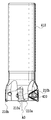
- FIG. 18 is a side view of the cutting edge-exchangeable cutting tool of FIG.
- FIG. 19 is a front view of the blade-tip-exchangeable cutting tool shown in FIG.
- the shape that approximates the upper surface 20 to a polygon is a triangle.
- the upper surface 20 has three edge portions LP and three corner portions CP.
- the term “side edge” means an edge portion of the end surface extending between the corner portions, and more specifically, regarding the upper surface, a portion other than the curved portion of the corner portion of the edge portion of the upper surface.
- one cutting edge is formed for one side ridge and one corner.
- each side ridge has a curved portion, and the curved portion can be considered as a corner portion, and the shape of the upper surface 20 can be regarded as a substantially hexagonal shape.
- each side ridge portion is regarded as having a curved portion that is convex outward.
- the upper surface 20 is regarded as a substantially triangular shape.
- the main cutting edge 22 of the cutting insert 10 has a shape in which the center portion is convexly curved outward when viewed from above, so that the cutting insert 10 has an appropriate size.
- the locus around the axis A3 of each part of the main cutting edge 22 is approximated on the same cylindrical surface. Therefore, the cutting tool 100 provided with the cutting insert 10 of the first embodiment can process a wall having a high squareness on the workpiece.
- the side ridge portion LP from which the main cutting edge 22 extends includes the linear portions 22b and 22c, so that the side portions of the cutting insert intersect with the end surfaces (upper and lower surfaces) become the linear portions 22b and 22c. Therefore, it becomes easy to make the surface contact with the side wall surface 121 (121a, 121b) of the insert mounting seat 120 shown in FIG. 9 more firmly with a sufficient contact area. That is, when the side ridge portion includes the linear portions 22b and 22c, the side surface portion (contact surface) having the linear portions 22b and 22c at the edges can be substantially flat. For this reason, the side wall surfaces 121a and 121b (as contacted surfaces) of the corresponding insert mounting seats 120 can also be substantially flat.
- the portion acting as the cutting edge of the working main cutting edge 22 on the upper surface 20 overlaps the position of the opening of the nick 41 formed on the lower surface 30, so that the working cutting edge 30 ⁇ / b> E on the lower surface 30
- the portion that has not been cut can be cut by the action cutting edge 20E of the upper surface 20.
- the three cutting edges 30E regarding the lower surface 30 are non-rotationally symmetric with respect to the three cutting edges 20E regarding the upper surface 20 around the axis A2. That is, the cutting edge 20E has a shape different from that of the cutting edge 30E.
Landscapes
- Engineering & Computer Science (AREA)
- Mechanical Engineering (AREA)
- Milling Processes (AREA)
Abstract
This cutting insert (10) can be used in perpendicular shoulder cutting. The cutting insert is provided with: a second cutting blade section (21, 21a) extending to a corner section; and a first cutting blade section (22) extending between corner sections (CP). The first cutting blade section (22) is, in a lateral view, provided with: a first inclined section (23a); a second inclined section (23b) inclined in the reverse direction of inclination with respect to the first inclined section; and a concave bottom section (23c) between the first and second inclined sections.
Description
本発明は、切削インサート、ボデーおよびこれらを備えた刃先交換式切削工具に関する。特に、本発明は、直角肩削り加工に適用できる切削インサートおよび刃先交換式切削工具に関する。
The present invention relates to a cutting insert, a body, and a cutting edge-exchangeable cutting tool including these. In particular, the present invention relates to a cutting insert and a cutting edge exchangeable cutting tool applicable to right-angle shoulder machining.
従来、略円柱状のボデーの先端部外周に複数の切削インサートを装着する刃先交換式切削工具の種類の一つに、特許文献1が開示するような90°の壁面を加工するための(つまり直角肩削り用の)ものがある。特許文献1が開示する切削インサートは、その上面の基本形状が略三角形であり、両面使用可能に構成されている。上下面の各々における切れ刃は同一構成を有する。各切れ刃は、主切れ刃と、副切れ刃と、コーナ切れ刃と、補助切れ刃とを備える。平面視において、この切削インサートは、略三角形形状輪郭を有し、辺稜部とコーナ縁部とが交互につながる。副切れ刃とコーナ切れ刃とはコーナ縁部に延在し、主切れ刃と補助切れ刃とはコーナ縁部間の辺稜部に延在する。副切れ刃は、コーナ切れ刃から、切削インサートを2等分するべく上下面の間に延びるように定められる仮想の中間面に向けて傾斜する。主切れ刃は同コーナ切れ刃から反対側に同中間面に向けて傾斜し、さらに補助切れ刃につながる。補助切れ刃は、主切れ刃と同じように、主切れ刃と副切れ刃との間のコーナ切れ刃から離れるにしたがい、中間面に近づくように傾斜する。補助切れ刃の中間面に対する傾斜度合いは主切れ刃の傾斜度合いよりも小さく、補助切れ刃は中間面に平行であり得る。補助切れ刃は、このように関連する主切れ刃から延び、隣接するコーナ切れ刃に従属する副切れ刃に接続する。
Conventionally, as one of the types of cutting edge-exchangeable cutting tools in which a plurality of cutting inserts are mounted on the outer periphery of the tip of a substantially cylindrical body, a 90 ° wall surface as disclosed in Patent Document 1 (that is, (For right-angle shoulder cutting). The cutting insert disclosed in Patent Document 1 has a substantially triangular basic shape on the upper surface, and is configured to be usable on both sides. The cutting edges in each of the upper and lower surfaces have the same configuration. Each cutting edge includes a main cutting edge, a secondary cutting edge, a corner cutting edge, and an auxiliary cutting edge. In plan view, this cutting insert has a substantially triangular contour, and the side ridges and the corner edges are alternately connected. The secondary cutting edge and the corner cutting edge extend to the corner edge, and the main cutting edge and the auxiliary cutting edge extend to the side ridge between the corner edges. The secondary cutting edge is inclined from the corner cutting edge toward an imaginary intermediate plane defined to extend between the upper and lower surfaces to bisect the cutting insert. The main cutting edge is inclined from the corner cutting edge to the opposite intermediate side and further to the auxiliary cutting edge. As with the main cutting edge, the auxiliary cutting edge is inclined so as to approach the intermediate surface as it moves away from the corner cutting edge between the main cutting edge and the auxiliary cutting edge. The inclination degree of the auxiliary cutting edge with respect to the intermediate surface is smaller than the inclination degree of the main cutting edge, and the auxiliary cutting edge may be parallel to the intermediate surface. The auxiliary cutting edge thus extends from the associated main cutting edge and connects to a secondary cutting edge that is subordinate to an adjacent corner cutting edge.
特許文献1の切削インサートがボデーに取り付けられて切削に用いられるとき、作用切れ刃は、1つのコーナ切れ刃と、このコーナ切れ刃の一端から順に延びる主切れ刃および補助切れ刃と、同じコーナ切れ刃の他端から延びる副切れ刃とからなる。側面視で、作用主切れ刃および作用補助切れ刃は、作用コーナ切れ刃から離れるに従い中間面に近づくように、延在する。作用補助切れ刃は、作用切れ刃でない隣の切れ刃の副切れ刃につながる。副切れ刃は、側面視で、同一切れ刃におけるコーナ切れ刃から離れるに従い中間面に近づくように傾斜し、その長さは主切れ刃の長さよりも明らかに短い。したがって、側面視において、副切れ刃の中間面に対する傾斜角は、主切れ刃の中間面に対する傾斜角よりもはるかに大きい。よって、作用切れ刃の作用補助切れ刃と、非作用切れ刃の副切れ刃との接続部での傾斜方向の交代は急激となる。したがって、切削工具において、1つの切れ刃が作用しているとき、作用補助切れ刃に接続する、非作用副切れ刃は作用切れ刃で生じた切りくずの流出を妨げる向きに延びる。これにより切りくずは非作用副切れ刃によって切削工具の基端側へ進むのが妨げられ、先端付近に滞留しやすくなる。その結果、工具と被加工物との間に切りくずが挟まったり、切りくずが被加工物の表面を傷つけたりする場合がある。
When the cutting insert of Patent Document 1 is attached to a body and used for cutting, the working cutting edge has one corner cutting edge, the same cutting edge as the main cutting edge and the auxiliary cutting edge that sequentially extend from one end of the corner cutting edge. It consists of a secondary cutting edge extending from the other end of the cutting edge. In a side view, the working main cutting edge and the working auxiliary cutting edge extend so as to approach the intermediate surface as they move away from the working corner cutting edge. The action assisting cutting edge leads to a secondary cutting edge of an adjacent cutting edge that is not the working cutting edge. The secondary cutting edge is inclined so as to approach the intermediate surface as it is away from the corner cutting edge of the same cutting edge in a side view, and its length is clearly shorter than the length of the main cutting edge. Therefore, in the side view, the inclination angle of the secondary cutting edge with respect to the intermediate surface is much larger than the inclination angle of the main cutting edge with respect to the intermediate surface. Therefore, the change in the inclination direction at the connecting portion between the action assisting edge of the action cutting edge and the auxiliary edge of the non-action edge becomes abrupt. Therefore, in the cutting tool, when one cutting edge is acting, the non-working auxiliary cutting edge connected to the working auxiliary cutting edge extends in a direction that prevents the outflow of chips generated by the working cutting edge. As a result, the chips are prevented from proceeding to the proximal end side of the cutting tool by the non-acting auxiliary cutting edge, and are liable to stay near the distal end. As a result, chips may be caught between the tool and the workpiece, or the chips may damage the surface of the workpiece.
さらに、切り込み量を多くして主切れ刃のほぼ全体を使用して切削を行うときがある。この場合、特許文献1の切削インサートを用いた切削工具では、特に作用主切れ刃の傾斜に応じて被加工物にそれをすくい上げる方向に力が加わってしまう場合がある。よって、被加工物をよりしっかりと保持することが必要である。
In addition, there are times when cutting is performed using almost the entire main cutting edge by increasing the cutting depth. In this case, in the cutting tool using the cutting insert of Patent Document 1, a force may be applied to the workpiece in the direction of scooping it up, particularly according to the inclination of the working main cutting edge. Therefore, it is necessary to hold the workpiece more firmly.
そこで、本発明は、上記の事情の少なくとも1つに鑑みて創案された切削インサート、該切削インサートが着脱自在に取り付けられる工具ボデー、およびその切削インサートが着脱自在に取り付けられる刃先交換式切削工具を提供することを目的とする。
Accordingly, the present invention provides a cutting insert created in view of at least one of the above circumstances, a tool body to which the cutting insert is detachably attached, and a cutting edge exchangeable cutting tool to which the cutting insert is detachably attached. The purpose is to provide.
本発明の一態様によれば、
略多角形形状の第1の端面と、その第1の端面に対向する第2の端面と、第1の端面と第2の端面とをつなぐ周側面と、第1の端面と周側面との交差部に形成された少なくとも1つの切れ刃とを備える切削インサートであって、
切れ刃は第1切れ刃部と、その第1切れ刃部につながる第2切れ刃部とを備え、
第1の端面についての切削インサートの端面視において、第2切れ刃部は第1の端面の互いに対して隣り合う2つのコーナ部のうちの第1コーナ部に位置し、第1切れ刃部は第1コーナ部から隣りの第2コーナ部に向けて延びる第1の端面の辺稜部に延在し、
第1の端面と第2の端面との間を通って周側面を通過する中間面を定めるとき、切削インサートの側面視において、第1切れ刃部は、該中間面に向けて凹形状に構成されていて、第1コーナ部側の第1傾斜部と、中間面に対する該第1傾斜部の傾斜方向に対して反対の傾斜方向を有して第1傾斜部に対して第2コーナ部側に位置する第2傾斜部と、第1傾斜部と第2傾斜部とをつなぐ凹底部とを備える、
切削インサートが提供される。 According to one aspect of the invention,
A first end surface having a substantially polygonal shape, a second end surface facing the first end surface, a peripheral side surface connecting the first end surface and the second end surface, and a first end surface and the peripheral side surface A cutting insert comprising at least one cutting edge formed at the intersection,
The cutting edge comprises a first cutting edge part and a second cutting edge part connected to the first cutting edge part,
In the end view of the cutting insert with respect to the first end surface, the second cutting edge portion is located at the first corner portion of the two corner portions adjacent to each other of the first end surface, and the first cutting edge portion is Extending from the first corner portion to the side edge portion of the first end surface extending toward the adjacent second corner portion;
When the intermediate surface passing through the peripheral side surface passing between the first end surface and the second end surface is defined, the first cutting edge portion is configured to be concave toward the intermediate surface in a side view of the cutting insert. A first inclined portion on the first corner portion side, and a second corner portion side with respect to the first inclined portion having an inclined direction opposite to the inclined direction of the first inclined portion with respect to the intermediate surface A second inclined part located at the bottom, and a concave bottom part connecting the first inclined part and the second inclined part,
A cutting insert is provided.
本発明の一態様の切削インサートによれば、第1切れ刃部は、側面視において、第1傾斜部と、該第1傾斜部と反対の傾斜方向で傾斜する第2傾斜部と、これらの間の凹底部とを備える。したがって、特許文献1の切削インサートに比べて、第1切れ刃部の切削により生じる切りくずが流出し易くなり、切りくずが工具と被加工物との間に挟まる等の問題を抑制できる。さらに、第1傾斜部と第2傾斜部との傾斜方向が逆であるので、切削加工中に被加工物が浮き上がる力を抑制することができ、よって被加工物の挙動または姿勢をより安定させることができる。また、この切削インサートでは、第2切れ刃部から第1切れ刃部にかけて、特に、その第1切れ刃部のより広い範囲を、さらに好ましくはその全体を作用切れ刃として用いることが可能になる。
According to the cutting insert of one aspect of the present invention, the first cutting edge portion includes a first inclined portion, a second inclined portion that is inclined in an inclination direction opposite to the first inclined portion, and these And a concave bottom portion in between. Therefore, compared with the cutting insert of patent document 1, the chip | tip produced by the cutting of a 1st cutting edge part becomes easy to flow out, and can suppress problems, such as a chip | tip being pinched between a tool and a to-be-processed object. Furthermore, since the inclination directions of the first inclined portion and the second inclined portion are opposite, it is possible to suppress the force by which the work piece is lifted during the cutting process, thereby further stabilizing the behavior or posture of the work piece. be able to. Moreover, in this cutting insert, it becomes possible to use the wider range of the 1st cutting edge part from the 2nd cutting edge part to the 1st cutting edge part, More preferably, the whole as a working cutting edge. .
好ましくは、第1の端面についての切削インサートの端面視において、第1切れ刃部は少なくとも部分的に外方に向けて凸に湾曲する。
Preferably, in the end view of the cutting insert with respect to the first end surface, the first cutting edge portion is curved at least partially convex outward.
前記第1切れ刃部が延在する辺稜部の2つのコーナ部間の中央からその両側に該辺稜部の長さの10%以下の範囲を定めるとき、該範囲内に、前記凹底部は最底部を有するとよい。
When the range of 10% or less of the length of the side ridge portion is determined from the center between the two corner portions of the side ridge portion where the first cutting edge portion extends to both sides thereof, the concave bottom portion is included in the range. May have a bottom.
前記切削インサートの端面視において、前記辺稜部は、隣り合う2つのコーナ部間でほぼ鏡像対称に形成されているとよい。
In the end view of the cutting insert, the side ridge portion may be formed substantially mirror-symmetric between two adjacent corner portions.
前記切削インサートの端面視において、前記第1切れ刃部は、その両端部側に少なくとも一つずつ直線状部分を備えるとよい。
In the end view of the cutting insert, it is preferable that the first cutting edge portion includes at least one linear portion on each end side.
好ましくは、前記第1の端面には、該第1の端面の切れ刃の数に応じた数の凹部が形成されている。各凹部は該第1の端面の関連する切れ刃の前記第1切れ刃部の凹底部近傍に設けられているとよい。
Preferably, the first end face is formed with a number of recesses corresponding to the number of cutting edges of the first end face. Each recess may be provided in the vicinity of the bottom of the first cutting edge of the associated cutting edge of the first end face.
上記切削インサートは、前記第1の端面と前記周側面との交差部に複数の切れ刃を備え、前記第2の端面と前記周側面との交差部に複数の切れ刃を備えてよい。この場合、前記第1の端面と前記第2の端面とを貫通するように延びる第1軸線を定めるとき、前記第1の端面に関する前記複数の切れ刃は該軸線に関して回転対称であり、該第1軸線に直交すると共に前記周側面を貫通するように延びる第2軸線を定めるとき、該第2軸線は前記中間面に含まれ、前記第2の端面に関する前記複数の切れ刃は、該第2軸線周りに、前記第1の端面に関する前記複数の切れ刃と回転対称であるとよい。
The cutting insert may include a plurality of cutting edges at the intersection between the first end surface and the peripheral side surface, and may include a plurality of cutting edges at the intersection between the second end surface and the peripheral side surface. In this case, when defining a first axis extending through the first end surface and the second end surface, the plurality of cutting edges with respect to the first end surface are rotationally symmetric with respect to the axis, When defining a second axis that is orthogonal to one axis and extends through the peripheral side surface, the second axis is included in the intermediate surface, and the plurality of cutting edges related to the second end surface are the second Around the axis, the plurality of cutting edges with respect to the first end face may be rotationally symmetric.
好ましくは、前記周側面は、前記第1切れ刃部に関して1つまたは複数の溝をさらに備える。これにより、切りくずを細分化して、切りくずの流出を円滑に改善することができる。よって、第1切れ刃部の中央部に加わる応力を緩和することができる。これらの溝の各々は前記第1の端面に開口部を有するとよい。前記溝のうちの少なくとも1つは、前記凹底部において前記第1切れ刃部と交差するとよい。好ましくは、前記溝は、前記凹底部のうちの最底部において、前記第1切れ刃部と交差する。前記第1の端面と前記第2の端面とを貫通するように延びる第1軸線を定めるとき、前記溝の各々は前記第1軸線に略平行に延在してもよい。このような溝を備える場合、第2の端面に関する複数の切れ刃は、上記第2軸線周りに、第1の端面に関する複数の切れ刃と非回転対称であるとよい。好ましくは、前記第1端面の端面視と前記第2端面の端面視とを重ねたとき、前記溝は、互いに対して重ならない。
Preferably, the peripheral side surface further includes one or a plurality of grooves with respect to the first cutting edge portion. Thereby, a chip can be subdivided and the outflow of a chip can be improved smoothly. Therefore, the stress applied to the center part of the first cutting edge part can be relaxed. Each of these grooves may have an opening at the first end face. At least one of the grooves may intersect the first cutting edge at the concave bottom. Preferably, the groove intersects the first cutting edge at the bottom of the concave bottom. When defining a first axis extending through the first end surface and the second end surface, each of the grooves may extend substantially parallel to the first axis. In the case of including such a groove, the plurality of cutting edges related to the second end face may be non-rotationally symmetric with the plurality of cutting edges related to the first end face around the second axis. Preferably, when the end face view of the first end face and the end face view of the second end face are overlapped, the grooves do not overlap each other.
前記第1の端面が第1当接面を有し、かつ、第2の端面が第2当接面を有する場合、該第1当接面に該第1の端面の切れ刃の数に応じた数の凹部が形成されていて、各凹部は該第1の端面の関連する切れ刃の前記第1切れ刃部の凹底部近傍に設けられ、該第2当接面に該第2の端面の切れ刃の数に応じた数の凹部が形成されていて、各凹部は該第2の端面の関連する切れ刃の前記第1切れ刃部の凹底部近傍に設けられているとよい。
When the first end surface has a first abutting surface and the second end surface has a second abutting surface, the first abutting surface depends on the number of cutting edges of the first end surface. A plurality of recesses are formed, each recess being provided near the bottom of the first cutting edge of the associated cutting edge of the first end face, and the second end face on the second abutting face It is preferable that the number of recesses corresponding to the number of cutting edges is formed, and each recess is provided in the vicinity of the bottom of the first cutting edge of the related cutting edge of the second end face.
前記第1の端面は略三角形状または略四角形形状であることができる。この場合、切削インサートは直角肩削りに適するように設計されるとよい。
The first end face may be substantially triangular or substantially rectangular. In this case, the cutting insert may be designed to be suitable for right-angle shoulder cutting.
本発明は、上記切削インサートを取り付けるためのインサート取り付け座を備える、刃先交換式切削工具のボデーにも存する。さらに、本発明は、少なくとも1つのインサート取付座を備えた工具ボデーを備えた刃先交換式切削工具であって、上記切削インサートが、該インサート取付座に着脱自在に取り付けられる、刃先交換式切削工具にも存する。この切削工具では、前記工具ボデーは略円筒状であり、インサート取付座は、切削インサートが取り付けられるとき、第1の端面または第2の端面が当接する底壁面を備えるとき、前記インサート取付座の底壁面に対向する方向から見るとき、前記切削インサートは、使用される前記第1切れ刃部が前記工具ボデーの回転軸線に対してほぼ平行になるように取り付けられるとよい。
The present invention also resides in a body of a cutting edge exchangeable cutting tool provided with an insert mounting seat for mounting the cutting insert. Furthermore, the present invention is a cutting edge exchangeable cutting tool having a tool body having at least one insert mounting seat, wherein the cutting insert is detachably mounted on the insert mounting seat. Also exists. In this cutting tool, the tool body is substantially cylindrical, and the insert mounting seat has a bottom wall surface against which the first end surface or the second end surface abuts when the cutting insert is mounted. When viewed from the direction facing the bottom wall surface, the cutting insert may be attached such that the first cutting edge portion used is substantially parallel to the rotation axis of the tool body.
以下、本発明の実施形態を、図面を用いて説明する。まず、本発明の第1実施形態について説明する。
Hereinafter, embodiments of the present invention will be described with reference to the drawings. First, a first embodiment of the present invention will be described.
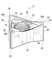
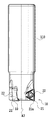
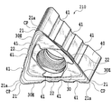
本発明の第1実施形態に係る切削インサート10は図1から図5に示される。切削インサート10は、直角肩削り用に形成されている。切削インサート10は、2つの対向する端面20、30と、これら2つの端面20、30をつなぐ周側面40とを備える。説明をわかりやすくするため、以降では、便宜的に、図1で上側を向いている一方の端面20を上面20と、他方の端面30を下面30と呼ぶ。なお、2つの端面20、30のうちのいずれか一方が本発明の第1の端面に相当し、残りの端面が本発明の第2の端面に相当する。
The cutting insert 10 according to the first embodiment of the present invention is shown in FIGS. The cutting insert 10 is formed for right-angle shoulder cutting. The cutting insert 10 includes two opposing end surfaces 20 and 30 and a peripheral side surface 40 that connects the two end surfaces 20 and 30. For ease of explanation, hereinafter, for convenience, one end surface 20 facing upward in FIG. 1 is referred to as an upper surface 20, and the other end surface 30 is referred to as a lower surface 30. One of the two end surfaces 20 and 30 corresponds to the first end surface of the present invention, and the remaining end surface corresponds to the second end surface of the present invention.
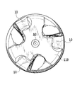
上面20を多角形に近似した形状は三角形である。上面20には、3つの辺稜部LPと3つのコーナ部CPとがある。ここで、用語「辺稜部」は、コーナ部間に延びる端面の縁部分を意味し、より具体的には上面に関していうと、上面の縁部のうちのコーナ部の曲線部分以外の部分をいう。実質的に、1つの辺稜部と1つのコーナ部とに関して、1つの切れ刃が形成される。なお、後述するように各辺稜部には曲線状部分があり、この曲線状部分をコーナ部として考えて上面20の形状を略六角形として捉えることもできる。しかしながら、以下の説明では便宜的に各辺稜部は概ね外方に凸の曲線状部分を有するとみなす。そして、上面20は略三角形であるとみなす。
The shape that approximates the upper surface 20 to a polygon is a triangle. The upper surface 20 has three edge portions LP and three corner portions CP. Here, the term “side edge” means an edge portion of the end surface extending between the corner portions, and more specifically, regarding the upper surface, a portion other than the curved portion of the corner portion of the edge portion of the upper surface. Say. In effect, one cutting edge is formed for one side ridge and one corner. As will be described later, each side ridge has a curved portion, and the curved portion can be considered as a corner portion, and the shape of the upper surface 20 can be regarded as a substantially hexagonal shape. However, in the following description, for convenience, each side ridge portion is regarded as having a curved portion that is convex outward. The upper surface 20 is regarded as a substantially triangular shape.
下面30も上面20同様に多角形に近似した形状は三角形である。それ故、下面30に、3つの辺稜部と3つのコーナ部とがあり、実質的に1つの辺稜部と1つのコーナ部とに関して1つの切れ刃が形成される。なお、下面30においても上面20と同様に各辺稜部は外方に凸の曲線状部分を有するとみなされる。
The lower surface 30 has a triangular shape similar to the upper surface 20 as well as a polygon. Therefore, the lower surface 30 has three side ridge portions and three corner portions, and one cutting edge is formed substantially for one side ridge portion and one corner portion. Note that, on the lower surface 30 as well as the upper surface 20, each side ridge portion is regarded as having an outwardly convex curved portion.
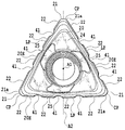
切削インサート10は、上面20と下面30とに開く貫通孔50を備える。上面20は貫通孔50の中心軸線A1に対して120°回転対称な形状になっている。下面30も上面20と同じく、貫通孔50の中心軸線A1に対して120°回転対称な形状になっている。
The cutting insert 10 includes a through hole 50 that opens on the upper surface 20 and the lower surface 30. The upper surface 20 has a shape that is 120 ° rotationally symmetric with respect to the central axis A1 of the through hole 50. Similarly to the upper surface 20, the lower surface 30 has a shape that is 120 ° rotationally symmetric with respect to the central axis A <b> 1 of the through hole 50.
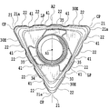
切削インサート10はいわゆるネガティブタイプの切削インサートである。よって、側面に正または負の逃げ角が特段付与されていない。さらに、上面20と下面30とは逆さまにしても同じ形状になっている。すなわち、切削インサート10を上面20に対向する側から見た図3(上面視または端面視)は、切削インサート10を下面30に対向する側から見た図5(下面視または端面視)と同じである。よって、切削インサート10は、軸線A1に直交すると共に周側面40を貫通するように定められる軸線A2周りに、180°回転対称である。ただし、図1では、3つの対称軸のうちの1つの対称軸が代表して軸線A2として示されている。
The cutting insert 10 is a so-called negative type cutting insert. Therefore, no special positive or negative clearance angle is given to the side surface. Furthermore, even if the upper surface 20 and the lower surface 30 are turned upside down, they have the same shape. That is, FIG. 3 (top view or end view) when the cutting insert 10 is viewed from the side facing the upper surface 20 is the same as FIG. 5 (bottom view or end view) when the cutting insert 10 is viewed from the side facing the lower surface 30. It is. Therefore, the cutting insert 10 is 180 ° rotationally symmetric about the axis A2 that is determined to be orthogonal to the axis A1 and penetrate the peripheral side surface 40. However, in FIG. 1, one of the three symmetry axes is representatively shown as the axis A2.
切削インサート10は、上面側の3つの切れ刃20Eと、下面側の3つの切れ刃30Eとを備える。切れ刃20Eは上面20と周側面40との交差部に形成される。切れ刃30Eは下面30と周側面40との交差部に形成される。上記説明から明らかなように、これら切れ刃20E、30Eは同一形状を有する。したがって、切削インサート10は両面使用可能な切削インサートであり、割出可能であり、6回使用可能である。各切れ刃は、関連する端面の一部がすくい面として機能するように形成され、関連する周側面の側面部分が逃げ面として機能するように形成されている。
The cutting insert 10 includes three cutting edges 20E on the upper surface side and three cutting edges 30E on the lower surface side. The cutting edge 20E is formed at the intersection of the upper surface 20 and the peripheral side surface 40. The cutting edge 30E is formed at the intersection of the lower surface 30 and the peripheral side surface 40. As is clear from the above description, the cutting edges 20E and 30E have the same shape. Therefore, the cutting insert 10 is a cutting insert that can be used on both sides, can be indexed, and can be used six times. Each of the cutting edges is formed so that a part of the related end surface functions as a rake face, and a side portion of the related peripheral side surface functions as a flank.
各切れ刃に関して考えると、周側面40は、各切れ刃に対する部分を有し、大きく3つに分けられ得る。上面20側の切れ刃20Eに着目すると、周側面40は3つの側面群に分けられ得、同様に、下面30側の切れ刃30Eに着目すると、周側面40は3つの側面群に分けられ得る。
Considering each cutting edge, the peripheral side surface 40 has a portion for each cutting edge and can be roughly divided into three. Focusing on the cutting edge 20E on the upper surface 20 side, the peripheral side surface 40 can be divided into three side groups. Similarly, if focusing on the cutting edge 30E on the lower surface 30 side, the peripheral side surface 40 can be divided into three side surface groups. .
切れ刃20E、30Eの各々は、主切れ刃、副切れ刃およびこれらをつなぐコーナ切れ刃を備える。以下、詳細に説明する。
Each of the cutting edges 20E and 30E includes a main cutting edge, a sub cutting edge, and a corner cutting edge connecting them. Details will be described below.
上面20および下面30の各辺稜部LPには主切れ刃22が形成され、上面20および下面30の各コーナ部CPにはコーナ切れ刃21が形成される。言い換えると、コーナ切れ刃21は上面20または下面30のコーナ部CPの曲線部分に形成され、主切れ刃22は隣り合う2つのコーナ切れ刃21同士をつなぐ辺稜部LPに、特にここではその全体に形成される。なお「主切れ刃」とは、切れ刃のうち切削加工時に加工の主な部分を担う部位である。この実施形態の切削インサート10では、切削加工時に辺稜部LPのほぼ全体を主切れ刃とすることができる。
A main cutting edge 22 is formed on each side ridge portion LP of the upper surface 20 and the lower surface 30, and a corner cutting edge 21 is formed on each corner portion CP of the upper surface 20 and the lower surface 30. In other words, the corner cutting edge 21 is formed in the curved portion of the corner portion CP of the upper surface 20 or the lower surface 30, and the main cutting edge 22 is formed on the side ridge portion LP that connects two adjacent corner cutting edges 21, particularly here. Formed entirely. The “main cutting edge” is a part of the cutting edge that bears the main part of the cutting process. In the cutting insert 10 of this embodiment, substantially the entire side ridge portion LP can be used as the main cutting edge during cutting.
さらに、各コーナ部CPには、コーナ切れ刃21に加えて、副切れ刃21aが形成されている。ここでは、副切れ刃21aは、コーナ部CPに形成されている。しかし、副切れ刃21aは、コーナ部にその一部がありかつ該コーナ部を超えて辺稜部に延びていてもよく、あるいはその全体が辺稜部に位置してもよい。
Further, in each corner portion CP, in addition to the corner cutting edge 21, a sub-cutting edge 21a is formed. Here, the auxiliary cutting edge 21a is formed in the corner portion CP. However, the minor cutting edge 21a may have a part in the corner portion and may extend beyond the corner portion to the side ridge portion, or the whole may be located in the side ridge portion.
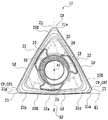
ここで、1つの切れ刃について説明する。ただし、上面側の3つの切れ刃20Eは同一形状であり、かつ、下面側の3つの切れ刃30Eはそれぞれ上面側の切れ刃20Eと同じ形状を有するので、以下では、上面20側の1つの切れ刃20Eに関して詳細に説明する。なお、本第1実施形態の切削インサートでは、主切れ刃22は、本発明における第1切れ刃部に対応し、コーナ切れ刃および副切れ刃は本発明における第2切れ刃部に対応する。具体的には、切削インサート10をボデーに取り付けたときに、コーナ部のうち壁面と直交する底面を切削する部分が副切れ刃となるが、この副切れ刃は、図3に示す上面視でコーナ部に位置する。つまり、切削インサート10における図3の上面視で、下方に位置する切れ刃20Eに着目すると、第2切れ刃部をなすコーナ切れ刃21および副切れ刃21aは上面20の互いに対して隣り合う2つのコーナ部CPのうちの一方の第1コーナ部CP1に位置し、第1切れ刃部としての主切れ刃22はこの第1コーナ部CP1から隣りの第2コーナ部CP2に向けて延びる上面20の辺稜部LPに延在する。なお、副切れ刃がコーナ部に延在しない場合、本発明の第2切れ刃部に副切れ刃は含まれない。
Here, one cutting edge will be described. However, since the three cutting edges 20E on the upper surface side have the same shape and the three cutting edges 30E on the lower surface side have the same shape as the cutting edge 20E on the upper surface side, respectively, The cutting edge 20E will be described in detail. In the cutting insert of the first embodiment, the main cutting edge 22 corresponds to the first cutting edge portion in the present invention, and the corner cutting edge and the sub cutting edge correspond to the second cutting edge portion in the present invention. Specifically, when the cutting insert 10 is attached to the body, the portion of the corner portion that cuts the bottom surface orthogonal to the wall surface becomes the secondary cutting edge. This secondary cutting edge is viewed from above as shown in FIG. Located in the corner. That is, when attention is paid to the cutting edge 20 </ b> E positioned below in the top view of the cutting insert 10 in FIG. 3, the corner cutting edge 21 and the sub-cutting edge 21 a forming the second cutting edge portion are adjacent to each other on the upper surface 20. An upper surface 20 located at one first corner portion CP1 of the two corner portions CP and having a main cutting edge 22 as a first cutting edge portion extending from the first corner portion CP1 toward the adjacent second corner portion CP2. It extends to the side ridge part LP. When the secondary cutting edge does not extend to the corner portion, the secondary cutting edge is not included in the second cutting edge portion of the present invention.
図3に示すように、上面視でそれぞれの主切れ刃22を見るとき、主切れ刃22は外方に向けて凸に湾曲している部分を有する。具体的には、主切れ刃22が概ね延在する辺稜部LPは、上面視で、切削インサート10の外方に向かって凸に湾曲する曲線状部分22aと、第1および第2直線状部分22b、22cとを備える。これら直線状部分22b、22cは曲線状部分22aを間に挟んでその両側に連続する。また、1つの切れ刃20Eにおける主切れ刃22は、隣りの切れ刃20Eの副切れ刃21aに連続するようにコーナ部間の辺稜部の概ね全体に亘って延在する。
As shown in FIG. 3, when each main cutting edge 22 is viewed from above, the main cutting edge 22 has a portion that is convexly curved outward. Specifically, the side ridge portion LP from which the main cutting edge 22 extends generally has a curved portion 22a that curves in a convex manner toward the outside of the cutting insert 10, and first and second linear shapes in a top view. Portions 22b and 22c. These linear portions 22b and 22c are continuous on both sides of the curved portion 22a. Further, the main cutting edge 22 in one cutting edge 20E extends over substantially the entire side ridge between the corners so as to be continuous with the sub-cutting edge 21a of the adjacent cutting edge 20E.
図3の切削インサート10の上面視において、各辺稜部LPは(軸線A2に重なる)仮想線Sに対して鏡像対称な形状になっている。2つの直線状部分22b、22cの端部のうち、曲線状部分22aから離れた側の端部同士を結んだ直線を弦(図3では、この弦の延長線がE1として示されている)とすると、仮想線Sは、この弦に直角であり、かつその弦の中央を通る線である。なお、図5では、仮想線Sに相当する下面30側の仮想線Tが表されている。
In the top view of the cutting insert 10 of FIG. 3, each side ridge portion LP has a mirror image symmetric shape with respect to the virtual line S (which overlaps the axis A2). Of the ends of the two linear portions 22b and 22c, a straight line connecting ends on the side away from the curved portion 22a is a string (in FIG. 3, an extension line of the string is shown as E1). Then, the virtual line S is a line that is perpendicular to the string and passes through the center of the string. In FIG. 5, a virtual line T on the lower surface 30 side corresponding to the virtual line S is shown.
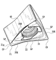
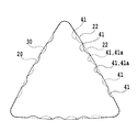
図4に示すように、切削インサート10の側面視(図1の軸線A2に沿った方向から切削インサートをみた図)で、上面20側の主切れ刃22を見るとき、主切れ刃22は下面30に向かって凹むように湾曲する。特に、切削インサート10では、その側面視で、主切れ刃22は、全体的に1つの滑らかな凹曲線を描くように凹湾曲する。図4において、主切れ刃22は、同一切れ刃20Eにおけるコーナ切れ刃21につながる第1傾斜部23aと、隣りの切れ刃20Eにつながる第2傾斜部23bと、これら第1および第2傾斜部間にこれらをつなぐように延在する凹底部(ここでは湾曲部分)23cとを備える。湾曲部分23の最下点、すなわち湾曲部分23が最も下面30に近づく箇所(つまり最底部)は、各辺稜部の中央付近にある。しかし、厳密には、主切れ刃22の側面視で、最底部は、同一切れ刃におけるコーナ切れ刃側に、主切れ刃22の中央からずらされている。より詳しく説明すると、本実施形態の切削インサート10においては、隣り合う2つのコーナ部CP1、CP2間の中央から、その2つのコーナ部の間にある辺稜部LPの長さの6%分だけ左側のコーナ部(上記第1コーナ部)CP1に寄った場所に、凹底部23cの最底部が配置される。なお、この辺稜部LPの長さとは、貫通孔の中心軸線に直交する平面上で定められるとよい。したがって、中心軸線A1と軸線A2とを含む平面(不図示)を定めたとき、凹底部23cの最底部はこの平面上から、第1コーナ部CP1側にずれている。
As shown in FIG. 4, when the main cutting edge 22 on the upper surface 20 side is viewed in a side view of the cutting insert 10 (view of the cutting insert from the direction along the axis A <b> 2 in FIG. 1), the main cutting edge 22 is the lower surface. Curved to dent toward 30. In particular, in the cutting insert 10, the main cutting edge 22 is concavely curved so as to draw one smooth concave curve as a whole in a side view. In FIG. 4, the main cutting edge 22 includes a first inclined portion 23a connected to the corner cutting edge 21 in the same cutting edge 20E, a second inclined portion 23b connected to the adjacent cutting edge 20E, and the first and second inclined portions. And a concave bottom portion (curved portion in this case) 23c extending so as to connect them therebetween. The lowest point of the curved portion 23, that is, the location where the curved portion 23 is closest to the lower surface 30 (that is, the bottom) is near the center of each side ridge. However, strictly speaking, in the side view of the main cutting edge 22, the bottom is shifted from the center of the main cutting edge 22 to the corner cutting edge side of the same cutting edge. More specifically, in the cutting insert 10 of the present embodiment, only 6% of the length of the side ridge portion LP between the two corner portions from the center between the two adjacent corner portions CP1 and CP2 is used. The bottom part of the concave bottom part 23c is arranged at a place near the left corner part (the first corner part) CP1. Note that the length of the side ridge portion LP may be determined on a plane orthogonal to the central axis of the through hole. Therefore, when a plane (not shown) including the central axis A1 and the axis A2 is defined, the bottom of the concave bottom 23c is shifted from the plane toward the first corner CP1.
主切れ刃22および辺稜部LPにおいて、上面視での第1直線状部分22bは側面視での第1傾斜部23aに対応し、上面視での第2直線状部分22cは側面視での第2傾斜部23bに対応し、上面視での曲線状部分22aは側面視での凹底部23cに対応する。しかし、これらは互いに対して完全に一致しているわけではない。
In the main cutting edge 22 and the side ridge portion LP, the first linear portion 22b in the top view corresponds to the first inclined portion 23a in the side view, and the second linear portion 22c in the top view is in the side view. Corresponding to the second inclined portion 23b, the curved portion 22a in the top view corresponds to the concave bottom portion 23c in the side view. However, they are not perfectly consistent with each other.
ここで、切削インサート10において軸線A1に直交すると共に周側面40を貫通するように延びる面を中間面Mとして定義する。なお、中間面Mは、ここでは、切削インサート10を2等分するように定められていて、軸線A2を含む。切れ刃20Eの主切れ刃22は、切削インサート10の上面視で両脇が直線状でかつ中央部で最も外方に凸であるように湾曲し、その側面視で両脇の各々の端部から中間面Mに向けて傾斜して凹底部23cで最も中間面Mに近づくように、構成されている。つまり、主切れ刃22は、側面視において、中間面Mに向けて凹形状に構成されている。したがって、切削インサート10の側面視において、第1傾斜部23aは同一切れ刃20Eにおけるコーナ切れ刃21から離れるに従い、中間面Mに近づくように傾斜する。同様に、第2傾斜部23bは隣りの切れ刃20Eにおける副切れ刃21aから離れるに従い、中間面Mに近づくように傾斜する。しかし、側面視において、第1傾斜部23aの中間面Mに対する傾斜方向は、第2傾斜部23bの中間面Mに対する傾斜方向と逆である。よって、図4において、第1傾斜部23aの中間面Mに対する傾斜を角度αで表すとき角度αは基準面から時計回りに測られ、第2傾斜部23bの中間面Mに対する傾斜を角度βで表すとき角度βは基準面から反時計回りに測られる。図4に示されるように、角度αの大きさは、角度βの大きさよりもわずかに大きいように定められているが、同一であっても、逆であってもよい。また、図4の側面視において、ここでは、第1および第2傾斜部23a、23bはそれぞれ、中間面Mに対して、一定の傾斜角を有している。しかし、第1傾斜部23aはそれがつながるコーナ切れ刃21から離れるしたがい中間面Mに対する傾斜角度が小さくなるように傾斜してもよく、また第2傾斜部23bはそれがつながる副切れ刃21aから離れるしたがい中間面Mに対する傾斜角度が小さくなるように傾斜してもよい。図4の側面視において、第1および第2傾斜部23a、23bのいずれか一方のみが、中間面Mに対して、一定の傾斜角を有してもよい。
Here, a surface perpendicular to the axis A1 and extending so as to penetrate the peripheral side surface 40 in the cutting insert 10 is defined as an intermediate surface M. Here, the intermediate surface M is determined so as to divide the cutting insert 10 into two equal parts, and includes the axis A2. The main cutting edge 22 of the cutting edge 20E is curved so that both sides are linear in the top view of the cutting insert 10 and convex outwardly at the center, and each end of each side in the side view. It is comprised so that it may incline toward the intermediate surface M and may approach the intermediate surface M most at the concave bottom part 23c. That is, the main cutting edge 22 is configured in a concave shape toward the intermediate surface M in a side view. Therefore, in the side view of the cutting insert 10, the first inclined portion 23a is inclined so as to approach the intermediate surface M as the distance from the corner cutting edge 21 in the same cutting edge 20E increases. Similarly, the 2nd inclination part 23b inclines so that the intermediate surface M may be approached, as it leaves | separates from the sub-cutting edge 21a in the adjacent cutting edge 20E. However, in the side view, the inclination direction with respect to the intermediate surface M of the first inclined portion 23a is opposite to the inclination direction with respect to the intermediate surface M of the second inclined portion 23b. Therefore, in FIG. 4, when the inclination with respect to the intermediate surface M of the first inclined portion 23a is represented by an angle α, the angle α is measured clockwise from the reference surface, and the inclination with respect to the intermediate surface M of the second inclined portion 23b is the angle β. When represented, the angle β is measured counterclockwise from the reference plane. As shown in FIG. 4, the angle α is determined to be slightly larger than the angle β, but may be the same or vice versa. In the side view of FIG. 4, here, the first and second inclined portions 23 a and 23 b each have a certain inclination angle with respect to the intermediate surface M. However, the first inclined portion 23a may be inclined so that the inclination angle with respect to the intermediate surface M becomes smaller as it is away from the corner cutting edge 21 to which the first inclined portion 23a is connected, and the second inclined portion 23b is separated from the auxiliary cutting edge 21a to which it is connected. As the distance increases, the inclination angle with respect to the intermediate surface M may be decreased. In the side view of FIG. 4, only one of the first and second inclined portions 23 a and 23 b may have a certain inclination angle with respect to the intermediate surface M.
副切れ刃21aは、切削インサート10の側面視において、同一切れ刃におけるコーナ切れ刃21から離れるに従い、中間面Mに近づくように傾斜する。
The secondary cutting edge 21a is inclined so as to approach the intermediate surface M as it is away from the corner cutting edge 21 of the same cutting edge in a side view of the cutting insert 10.
上面20には後述するボデーの壁面に当接することができるように構成された当接面24を有する。当接面24は、貫通孔50の周囲に延在している。上面20の切れ刃20Eは、当接面24よりも高い位置にある。すなわち、上面20の切れ刃20Eの各部分(コーナ切れ刃21、主切れ刃22または副切れ刃21a)から下面30または中間面Mまでの距離は当接面24の各部分から下面30または中間面Mまでの距離よりも長い。下面30においても当接面34が形成されていて、この当接面34と切れ刃30Eとの関係も、当接面24と切れ刃20Eとの関係と同様である。
The upper surface 20 has an abutment surface 24 configured to be able to abut against a wall surface of a body described later. The contact surface 24 extends around the through hole 50. The cutting edge 20 </ b> E of the upper surface 20 is at a position higher than the contact surface 24. That is, the distance from each portion of the cutting edge 20E (the corner cutting edge 21, the main cutting edge 22 or the auxiliary cutting edge 21a) of the upper surface 20 to the lower surface 30 or the intermediate surface M is from each portion of the contact surface 24 to the lower surface 30 or intermediate. It is longer than the distance to the surface M. A contact surface 34 is also formed on the lower surface 30, and the relationship between the contact surface 34 and the cutting edge 30E is the same as the relationship between the contact surface 24 and the cutting edge 20E.
図3に示すように、上面20には、下面30の切れ刃が作用切れ刃とされるときに、ボデーに形成されるインサート取付座の底壁面に当接する当接面24が形成される。当接面24は3つの凹部25を備える。凹部25の数は切れ刃20Eの数に一致する。各凹部25は、関連する切れ刃20Eの主切れ刃22における図4の凹底部23cの近傍に配置されている。したがって、図3の下方の主切れ刃22aの近くに位置する凹部25は上記仮想線Sと交差する。特に、各凹部25は、凹底部23cの中でも上記最底部に関して形成され、(図3において切れ刃に略直交する方向での)最底部の内側に延在する。なお、凹部25と切れ刃20Eとの間には、すくい面に相当する部分が延在する。
As shown in FIG. 3, the upper surface 20 is formed with a contact surface 24 that comes into contact with the bottom wall surface of the insert mounting seat formed on the body when the cutting edge of the lower surface 30 is a working cutting edge. The contact surface 24 includes three recesses 25. The number of recesses 25 matches the number of cutting edges 20E. Each recessed part 25 is arrange | positioned in the vicinity of the concave bottom part 23c of FIG. 4 in the main cutting edge 22 of the related cutting edge 20E. Accordingly, the concave portion 25 located near the lower main cutting edge 22a in FIG. 3 intersects the imaginary line S. In particular, each concave portion 25 is formed with respect to the above-mentioned bottom portion among the concave bottom portions 23c, and extends inside the bottom portion (in a direction substantially perpendicular to the cutting edge in FIG. 3). A portion corresponding to the rake face extends between the recess 25 and the cutting edge 20E.
下面30においても、上面20と同様に、当接面34が形成されている。当接面34には、3つの凹部35が設けられている。当接面34と切れ刃30Eとの関係は当接面24と切れ刃20Eとの関係と同様である。また、凹部35は凹部25と同じ形状を有し、凹部25と同様に切れ刃30Eの主切れ刃に対して設けられる。
Also on the lower surface 30, as with the upper surface 20, a contact surface 34 is formed. The contact surface 34 is provided with three recesses 35. The relationship between the contact surface 34 and the cutting edge 30E is the same as the relationship between the contact surface 24 and the cutting edge 20E. Moreover, the recessed part 35 has the same shape as the recessed part 25, and is provided with respect to the main cutting edge of the cutting edge 30E similarly to the recessed part 25.
次に、上述した切削インサート10が着脱自在に装着される刃先交換式切削工具について説明する。本第1実施形態の刃先交換式切削工具100は、上述した切削インサート10と、略円筒状の工具ボデー110と、を備える。なお、切削工具100は主として直角肩削り加工に適するように構成されている。
Next, a description will be given of a cutting edge replaceable cutting tool to which the above-described cutting insert 10 is detachably mounted. The cutting edge-replaceable cutting tool 100 according to the first embodiment includes the above-described cutting insert 10 and a substantially cylindrical tool body 110. The cutting tool 100 is configured to be suitable mainly for right-angle shoulder machining.
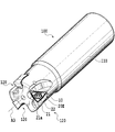
ボデー110は先端部から基端部に延びる軸線A3を有する。ボデー110の先端部には切削インサート10を取り付けるためのインサート取付座120が周方向において等間隔に3つ形成されている。
The body 110 has an axis A3 extending from the distal end portion to the proximal end portion. Three insert mounting seats 120 for mounting the cutting insert 10 are formed at the tip of the body 110 at equal intervals in the circumferential direction.
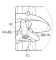
インサート取付座120は、2つの側壁面121(121a、121b)と、これらに交差するように、特にここでは略直角に延在する底壁面122とを備える。切削インサート10がインサート取付座120に取り付けられるとき、切削インサート10の周側面の側面部分が側壁面121に当接し、上面20または下面30が底壁面122に当接する。
The insert mounting seat 120 includes two side wall surfaces 121 (121a, 121b) and a bottom wall surface 122 that extends at a substantially right angle so as to intersect with the two side wall surfaces 121 (121a, 121b). When the cutting insert 10 is attached to the insert mounting seat 120, the side surface portion of the peripheral side surface of the cutting insert 10 contacts the side wall surface 121, and the upper surface 20 or the lower surface 30 contacts the bottom wall surface 122.
インサート取付座120では、切削インサート10は1つの主切れ刃22の全体がボデー110の外周側に位置するように載置される。厳密には、刃先交換式切削工具100をその回転軸線A3を中心に回転させたとき、主切れ刃22全体の回転軌跡が回転軸線と概ね平行な円筒面を描くような姿勢で切削インサート10はインサート取付座120に載置される。そのため、1つのインサート取付座120の底壁面122に対向する方向から切削工具100を見るとき、切削インサート10は、使用される主切れ刃(作用主切れ刃)が工具ボデー110の回転軸線A3に対してほぼ平行になるように取り付けられる。また、切削インサート10の周側面40の側面部分が被加工物の表面と接触することを防ぐため、切削インサート10は刃先交換式切削工具100の回転方向前方側に傾斜して載置される。すなわちネガティブタイプの切削インサート10の逃げ面に、各種の正の逃げ角が付与されるように、切削インサート10は、刃先交換式切削工具100のボデー110に取り付けられる。
In the insert mounting seat 120, the cutting insert 10 is placed such that the entire main cutting edge 22 is positioned on the outer peripheral side of the body 110. Strictly speaking, when the cutting edge 100 is rotated about its rotation axis A3, the cutting insert 10 is in such a posture that the rotation trajectory of the main cutting edge 22 draws a cylindrical surface substantially parallel to the rotation axis. It is mounted on the insert mounting seat 120. Therefore, when the cutting tool 100 is viewed from the direction facing the bottom wall surface 122 of one insert mounting seat 120, the cutting insert 10 has a main cutting edge (working main cutting edge) used on the rotation axis A3 of the tool body 110. It is attached so as to be substantially parallel to the surface. Further, in order to prevent the side surface portion of the peripheral side surface 40 of the cutting insert 10 from coming into contact with the surface of the workpiece, the cutting insert 10 is tilted and placed on the front side in the rotational direction of the cutting edge exchangeable cutting tool 100. That is, the cutting insert 10 is attached to the body 110 of the cutting edge exchangeable cutting tool 100 so that various positive clearance angles are given to the flank of the negative type cutting insert 10.
次に、本実施形態の切削インサート10およびそれが着脱自在に取り付けられた切削工具100が奏する作用と効果について説明する。
Next, the operation and effect of the cutting insert 10 of this embodiment and the cutting tool 100 to which it is detachably attached will be described.
切削工具100は、軸線A3周りに回転されて、被加工物に対して動かされる。これにより、直角肩削り加工を行うことができる。軸線A3は切削工具の被加工物に対する相対回転軸である。切削工具100が固定され、被加工物が回転されてもよい。
The cutting tool 100 is rotated around the axis A3 and moved relative to the workpiece. Thereby, right-angle shoulder machining can be performed. The axis A3 is a relative rotation axis with respect to the workpiece of the cutting tool. The cutting tool 100 may be fixed and the workpiece may be rotated.
図4に示す切削インサート10の側面視において、主切れ刃22は凹湾曲した形状を有し、上面20から下面30へと向かって凹む湾曲部分23cを備える。なおかつ、その湾曲部分23cの側面視での最下部つまり凹底部が辺稜部の中央付近にある。したがって、切りくずの流出ないしは排出を好適に促すことができる。
In the side view of the cutting insert 10 shown in FIG. 4, the main cutting edge 22 has a concavely curved shape and includes a curved portion 23 c that is recessed from the upper surface 20 toward the lower surface 30. In addition, the lowermost portion, that is, the concave bottom portion in the side view of the curved portion 23c is near the center of the side ridge portion. Accordingly, it is possible to favor the outflow or discharge of chips.
ここで、特許文献1に記載の切削インサートと、本第1実施形態の切削インサート10とを比較する。特許文献1の切削インサートでは、上で述べたように、作用主切れ刃の延長上に、作用切れ刃でない切れ刃の副切れ刃が延在する。この従来の副切れ刃は、作用切れ刃からの切りくずの流れを妨げる向きに延在し(つまり中間面に対して大きな立ち上がり角度を有し)、その副切れ刃に連なるすくい面部分も同様にその流れを妨げるように働き得る。したがって、切りくずの流出方向は非作用副切れ刃およびその周囲により切削工具の先端側に向けられ、切りくずが工具と被加工物との間に挟まったり、被加工物の表面を傷つけたりすることが生じ得る。しかしながら、本実施形態の切削インサート10では主切れ刃は、それ自体が側面視で滑らかにかつ緩やかに凹湾曲するので、特に、第2傾斜部23bの立ち上がり角(角度βに相当)が小さく第2傾斜部23bが凹底部23cから緩やかに立ち上がるので、切りくずは滑らかに切削工具の軸線A3に沿った方向において基端側に向かわせられることが可能になる。よって、切削インサート10および切削工具100によれば、切りくずの流出抵抗を減らし、びびり等の振動発生を抑制し、かつ、被加工面の精度を高めることができる。
Here, the cutting insert described in Patent Document 1 is compared with the cutting insert 10 of the first embodiment. In the cutting insert of Patent Document 1, as described above, the secondary cutting edge of the cutting edge that is not the working cutting edge extends on the extension of the working main cutting edge. This conventional secondary cutting edge extends in a direction that obstructs the flow of chips from the working cutting edge (that is, has a large rising angle with respect to the intermediate surface), and the rake face portion connected to the secondary cutting edge is the same. Can work to hinder its flow. Therefore, the flow direction of chips is directed to the tip side of the cutting tool by the non-acting secondary cutting edge and its surroundings, and the chips are sandwiched between the tool and the workpiece, or the surface of the workpiece is damaged. Can happen. However, in the cutting insert 10 of the present embodiment, the main cutting edge itself is smoothly and gently curved in a side view, so that the rising angle (corresponding to the angle β) of the second inclined portion 23b is particularly small. Since the two inclined portions 23b rise gently from the concave bottom portion 23c, the chips can be smoothly directed toward the proximal end in the direction along the axis A3 of the cutting tool. Therefore, according to the cutting insert 10 and the cutting tool 100, the outflow resistance of chips can be reduced, the occurrence of vibrations such as chatter can be suppressed, and the accuracy of the work surface can be increased.
このような切りくずの流出を確実にするように、第1傾斜部23aの中間面Mに対する傾斜を角度αおよび第2傾斜部23bの中間面Mに対する傾斜を角度βは、大きさにおいて、大きな角度差を有しないとよい。例えば、角度αの大きさと、角度βの大きさとの間の差は、10°以下であるとよい。また、角度αの大きさは20°以下であるとよく、角度βの大きさも20°以下であるとよい。
In order to ensure such outflow of chips, the angle α is inclined with respect to the intermediate surface M of the first inclined portion 23a, and the angle β is inclined with respect to the intermediate surface M of the second inclined portion 23b. It is good not to have an angle difference. For example, the difference between the magnitude of the angle α and the magnitude of the angle β may be 10 ° or less. Further, the angle α is preferably 20 ° or less, and the angle β is preferably 20 ° or less.
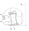
さらに、上記切削工具100では、切削加工時、特に被加工物への切り込みが大きいとき、被加工物を押し上げる方向の第1力のみならず、被加工物を押し下げる方向の第2力を適度に生じさせることができる。図10に図7の切削工具の先端部の一部を示す。図10では、被加工物は省略されているが、主切れ刃22のうちの第1傾斜部23aのみならず、凹底部23cおよび第2直線状部分22cも、被加工物の加工に用いられている場合の、第1力F1と第2力F2とがそれらの相対的な方向のみに着目して模式的に表されている。切削インサート10および切削工具100によれば、切削工具の先端側を向いた成分を含む第2力F2により、第1力F1の切削工具の基端側を向いた力(の成分)を緩和できるので、切削時に被加工物を浮き上がらせる力を抑制できる。よって、切削インサート10および切削工具100によれば、被加工物の保持力を従来ほど要求されないという効果が奏され得る。
Further, in the cutting tool 100, when the cutting is performed, particularly when the cut into the workpiece is large, not only the first force in the direction of pushing up the workpiece but also the second force in the direction of pushing down the workpiece is appropriately set. Can be generated. FIG. 10 shows a part of the tip of the cutting tool of FIG. In FIG. 10, the workpiece is omitted, but not only the first inclined portion 23 a of the main cutting edge 22 but also the concave bottom portion 23 c and the second linear portion 22 c are used for processing the workpiece. The first force F1 and the second force F2 are schematically represented by paying attention only to their relative directions. According to the cutting insert 10 and the cutting tool 100, the force (component) of the first force F1 facing the proximal end side of the cutting tool can be reduced by the second force F2 including the component facing the distal end side of the cutting tool. Therefore, the force which lifts up a workpiece at the time of cutting can be suppressed. Therefore, according to the cutting insert 10 and the cutting tool 100, the effect that the holding force of a workpiece is not required as in the related art can be achieved.
主切れ刃22は図4の側面視で凹湾曲した形状を有するが、主切れ刃22が延在する辺稜部が上面視または端面視で曲線状部分22aを備えることで、切削工具100は直角度の高い壁面を加工することができる。例えば、上面視で主切れ刃が単一の直線のみで構成されている切削インサートが、プラスまたはマイナスのアキシャルレーキでボデーに装着された場合、主切れ刃の中央部分が描く軸線A3周りの軌跡が主切れ刃の端部が描く同軌跡の内側に入ってしまう。そのため、加工された壁面はその中央部分が手前に盛り上がったような形状となる。しかしながら、本第1実施形態の切削インサート10の主切れ刃22は、上面視したとき、その中央部が外方に向かって凸に湾曲する形状であるため、切削インサート10が適切な大きさのアキシャルレーキでボデー110に装着されると主切れ刃22の各部の軸線A3周りの軌跡が同一円筒面上に近似される。そのため、第1実施形態の切削インサート10を備えた切削工具100では被加工物に直角度の高い壁面を加工できる。
The main cutting edge 22 has a concavely curved shape in a side view of FIG. 4, but the cutting edge 100 includes a curved portion 22a in a side ridge portion from which the main cutting edge 22 extends in a top view or an end view. A wall with a high squareness can be processed. For example, when a cutting insert whose main cutting edge is composed of only a single straight line when mounted on the body with a positive or negative axial rake, the locus about the axis A3 drawn by the central portion of the main cutting edge is shown. Falls inside the same trajectory drawn by the end of the main cutting edge. Therefore, the processed wall surface has a shape in which the central portion is raised to the front. However, the main cutting edge 22 of the cutting insert 10 according to the first embodiment has a shape in which the center portion is convexly curved outward when viewed from above, so that the cutting insert 10 has an appropriate size. When mounted on the body 110 by the axial rake, the locus around the axis A3 of each part of the main cutting edge 22 is approximated on the same cylindrical surface. Therefore, the cutting tool 100 provided with the cutting insert 10 of the first embodiment can process a wall having a high squareness on the workpiece.
ここで、上面20の切れ刃20Eを作用切れ刃とする場合をまず考える。主切れ刃22は側面視で凹底部23cを有して凹湾曲する。したがって、切削工具100による切削により、側面視における切れ刃形状に対応する、V字に折れ曲がった断面形状の切りくずが生成される。一方、切れ刃20Eは、全体的に当接面24よりも高い位置(中間面Mから離れた位置)にある。そのため、V字状の切りくずは当接面24上に至り易い。しかし、切削インサート10では、主切れ刃の略中央部分の近傍に凹部25が設けられているので、その切りくずのV形状の中央部分は凹部25の底部に擦過し、切りくずの両端部が当接面24に接触する前に切りくずは切削インサート10から離れ易い。このため、当接面24が切りくずにより擦過されることは抑制され、当接面24の損傷は防がれる。したがって、切削インサート10において平坦である当接面24は、ほぼ平坦な状態が維持される。このことにより、上面20側の切れ刃20Eを使用した後に下面30側の切れ刃30Eを使用するとき、上面20の当接面24をインサート取付座120の底壁面122に十分にしっかりと当接させることができる。同様に、下面30の切れ刃30Eを使用した後、上面20の切れ刃20Eを使用する場合にも、当接面34がきれいなので、切削インサート10はインサート取付座により安定的に装着される。なお、凹部25および凹部35は切削インサートの取付の安定性を確保するという観点から、切りくずが強く擦過する範囲を考慮した必要最小限度の大きさであることが好ましい。つまり、当接面24および当接面34はその大きさが小さいほど切削インサートの取付安定性が低下することから、凹部25および凹部35は切りくずを当接面24および当接面34に擦過させない効果が生じる最小限の大きさであることが好ましい。
Here, first consider the case where the cutting edge 20E on the upper surface 20 is the working cutting edge. The main cutting edge 22 has a concave bottom 23c in a side view and is concavely curved. Therefore, by cutting with the cutting tool 100, chips having a cross-sectional shape bent into a V shape corresponding to the cutting edge shape in a side view are generated. On the other hand, the cutting edge 20E is at a position higher than the contact surface 24 as a whole (a position away from the intermediate surface M). Therefore, the V-shaped chip tends to reach the contact surface 24. However, in the cutting insert 10, since the concave portion 25 is provided in the vicinity of the substantially central portion of the main cutting edge, the V-shaped central portion of the chip rubs against the bottom portion of the concave portion 25, and both end portions of the chip are formed. Chips are likely to leave the cutting insert 10 before contacting the abutment surface 24. For this reason, it is suppressed that the contact surface 24 is rubbed by a chip, and damage to the contact surface 24 is prevented. Therefore, the contact surface 24 that is flat in the cutting insert 10 is maintained in a substantially flat state. Accordingly, when the cutting edge 30E on the lower surface 30 side is used after the cutting edge 20E on the upper surface 20 side is used, the contact surface 24 of the upper surface 20 sufficiently contacts the bottom wall surface 122 of the insert mounting seat 120. Can be made. Similarly, when using the cutting edge 20E on the upper surface 20 after using the cutting edge 30E on the lower surface 30, the abutment surface 34 is clean, so that the cutting insert 10 is stably mounted on the insert mounting seat. In addition, it is preferable that the recessed part 25 and the recessed part 35 are the minimum required size in consideration of the range which a chip | tip scrapes strongly from a viewpoint of ensuring the stability of attachment of a cutting insert. In other words, the smaller the size of the contact surface 24 and the contact surface 34, the lower the mounting stability of the cutting insert. Therefore, the recess 25 and the recess 35 scrape chips into the contact surface 24 and the contact surface 34. It is preferable that the size is a minimum size that does not cause an effect.
また、主切れ刃22が延びる辺稜部LPが直線状部分22b、22cを備えることで、切削インサートの側面部分は、端面(上下面)との交差部が直線状部分22b、22cとなる。したがって、図9に示すインサート取付座120の側壁面121(121a、121b)に、十分な接触面積でよりしっかりと面接触させることが容易になる。すなわち辺稜部が直線状部分22b、22cを備えることで、その直線状部分22b、22cを縁部に有する側面部分(当接面)を略平面とすることができる。このため、対応するインサート取付座120の(被当接面としての)側壁面121a、121bも略平面とすることができる。インサート取付座120の壁面を複雑な曲面形状として形成する必要がないため、インサート取付座120の壁面を、切削インサート10の形状に高精度で合うように形成することが容易に可能となる。これにより、より好適に、切削インサートの当接面としての側面部分をインサート取付座の被当接面に面接触させることが容易になる。このことにより、切削インサート10の取付け安定性が向上する。
Further, the side ridge portion LP from which the main cutting edge 22 extends includes the linear portions 22b and 22c, so that the side portions of the cutting insert intersect with the end surfaces (upper and lower surfaces) become the linear portions 22b and 22c. Therefore, it becomes easy to make the surface contact with the side wall surface 121 (121a, 121b) of the insert mounting seat 120 shown in FIG. 9 more firmly with a sufficient contact area. That is, when the side ridge portion includes the linear portions 22b and 22c, the side surface portion (contact surface) having the linear portions 22b and 22c at the edges can be substantially flat. For this reason, the side wall surfaces 121a and 121b (as contacted surfaces) of the corresponding insert mounting seats 120 can also be substantially flat. Since it is not necessary to form the wall surface of the insert mounting seat 120 as a complicated curved surface shape, it is possible to easily form the wall surface of the insert mounting seat 120 so as to match the shape of the cutting insert 10 with high accuracy. This makes it easier to bring the side surface portion as the contact surface of the cutting insert into surface contact with the contacted surface of the insert mounting seat. This improves the mounting stability of the cutting insert 10.
切削インサート10は切れ刃20E、30Eを合計で六つ有し、6回の使用が可能である。切削インサート10は周側面40が貫通孔50の中心軸線A1に概ね平行であるように構成されていて、上下を逆さまにしても同じ形状の切れ刃を使用できる、いわゆるネガティブタイプの切削インサートである。このため、切削インサート10は、上面20に加えて下面30にも切れ刃が形成され、経済的である。
The cutting insert 10 has six cutting edges 20E and 30E in total, and can be used six times. The cutting insert 10 is a so-called negative type cutting insert that is configured so that the peripheral side surface 40 is substantially parallel to the central axis A1 of the through-hole 50, and can use a cutting blade having the same shape even if it is turned upside down. . For this reason, the cutting insert 10 is economical because a cutting edge is formed on the lower surface 30 in addition to the upper surface 20.
また、上で述べたように、上面視したときおよび下面視したときのそれらの各辺稜部が鏡像対称な形状となることで、単純な形状の通常の金型で、切削インサート10を製造することが可能になり、製造コストが低減する。すなわち、両面に切れ刃が形成される通常のネガティブタイプの切削インサートとして製造することが可能となる。
Further, as described above, when each of the side ridges when viewed from above and viewed from below is a mirror image symmetrical shape, the cutting insert 10 is manufactured with a simple die having a simple shape. Manufacturing costs can be reduced. That is, it can be manufactured as a normal negative type cutting insert in which cutting edges are formed on both sides.
以上、本発明の第1実施形態について説明したが、種々の変更が可能である。例えば、上述した切削インサート10はネガティブタイプであったが、逃げ面相当部分が貫通孔の中心軸線に直交すると共に切れ刃を通る平面に対して鋭角をなすように構成されても、つまりポジティブタイプであっても構わない。また上下面の両方に切れ刃を形成し、かつ側面の上下面付近のみポジティブタイプとされ、側面全体としては凹面形状とされても構わない。
The first embodiment of the present invention has been described above, but various modifications can be made. For example, the above-described cutting insert 10 is a negative type, but the portion corresponding to the flank is orthogonal to the central axis of the through-hole and is configured to form an acute angle with respect to the plane passing through the cutting edge. It does not matter. Further, cutting edges may be formed on both the upper and lower surfaces, and only the vicinity of the upper and lower surfaces of the side surface may be a positive type, and the entire side surface may have a concave shape.
さらに、上記切削インサートでは、すくい面となる端面部分は正のすくい角を有するように形成された(図1、図2、および図4参照)。しかし、各端面に、各種凸部や凹部がさらに設けられてもよい。
Furthermore, in the above-mentioned cutting insert, the end face portion that becomes the rake face was formed to have a positive rake angle (see FIGS. 1, 2, and 4). However, various convex portions and concave portions may be further provided on each end face.
上述した実施形態では上面および下面の基本形状は三角形であったが、四角形等の別の多角形であってもよい。上記切削インサート10のように上下面の基本形状が三角形であったり四角形であったりする場合、切削インサートは、上述のごとく、切りくずの排出が重要になる直角肩削り加工に適するように設計され得る。その場合には上記効果が一層有効に機能する。
In the above-described embodiment, the basic shape of the upper surface and the lower surface is a triangle, but may be another polygon such as a quadrangle. When the basic shape of the upper and lower surfaces is triangular or quadrangular like the above-mentioned cutting insert 10, the cutting insert is designed to be suitable for right-angle shoulder cutting where chip discharge is important as described above. obtain. In that case, the above effect functions more effectively.
上述した実施形態では主切れ刃が延在する辺稜部は上面視において曲線状部分と直線状部分とで構成されていたが、曲線状部分だけで構成されていても構わない。また、工具軸線周りの主切れ刃全体の軌跡が同一円筒面上に近似される限り、主切れ刃または辺稜部に直線状部分が3つ以上あっても構わない。
In the embodiment described above, the side ridge where the main cutting edge extends is composed of a curved portion and a straight portion in a top view, but may be composed of only a curved portion. Further, as long as the trajectory of the entire main cutting edge around the tool axis is approximated on the same cylindrical surface, there may be three or more linear portions on the main cutting edge or the side ridge.
上述した実施形態では凹底部23cの最底部は、隣り合う2つのコーナ部間の中央から、その2つのコーナ部の間にある辺稜部の長さの6%分片側にずれた位置にあった。しかし、隣り合う2つのコーナ部間の中央を基点として左右に辺稜部の長さの10%以下の範囲を定め、その範囲内に凹底部23cの最底部が配置されれば十分な効果が生じる。つまり、凹底部23cの最底部は二つのコーナ部間の中央から最大で辺稜部の長さの10%まで左右のいずれかの方向にずれることができる。
In the embodiment described above, the bottom of the concave bottom 23c is located at a position shifted from the center between two adjacent corners to one side by 6% of the length of the side ridge between the two corners. It was. However, a sufficient effect can be obtained if a range of 10% or less of the length of the side ridge portion is determined on the left and right with the center between two adjacent corner portions as a base point, and the bottom of the concave bottom portion 23c is disposed within the range. Arise. In other words, the bottom of the concave bottom 23c can be shifted in the left or right direction from the center between the two corners up to 10% of the length of the side ridge.
上述した実施形態では上面および下面の辺稜部はそれぞれ上面視および下面視で鏡像対称な形状であったが、それに限定されない。直角肩削り加工用の切削工具の場合、主切れ刃全体の軌跡が同一円筒面上に近似されればよい。
In the above-described embodiment, the side ridges on the top surface and the bottom surface are mirror-symmetrical shapes in the top view and the bottom view, respectively, but are not limited thereto. In the case of a cutting tool for right-angle shoulder machining, the trajectory of the entire main cutting edge may be approximated on the same cylindrical surface.
凹部25、35は、片面にのみ切れ刃が形成されている切削インサートにも適用されることができる。例えば上面20側にのみ切れ刃20Eが形成されている場合、上記のごとく凹部25を設けることで、切りくずが切削インサートから離れることを促すことができる。したがって、切りくずの擦過により上面20が傷つくことを抑制することができる。これは、上面20側の未使用の切れ刃を良好な状態に保つことに寄与する。
The recesses 25 and 35 can also be applied to a cutting insert in which a cutting edge is formed only on one side. For example, when the cutting edge 20E is formed only on the upper surface 20 side, it is possible to prompt the chip to be separated from the cutting insert by providing the recess 25 as described above. Therefore, it is possible to prevent the upper surface 20 from being damaged by scraping of chips. This contributes to keeping the unused cutting edge on the upper surface 20 side in a good state.
次に、本発明の第2実施形態について説明する。第2実施形態の切削インサート210は第1実施形態の上記切削インサートに所謂ニックをさらに設けた構成を備える。第2実施形態の切削工具400は、第2実施形態の切削インサートのその特徴部分に対応して、上記第1実施形態の切削工具と相違点を有する。そこで、以下では、それら相違点に関して説明して、既に説明した構成に相当する構成には既に用いた符号を付し、それらの説明を省略する。
Next, a second embodiment of the present invention will be described. The cutting insert 210 of the second embodiment has a configuration in which a so-called nick is further provided in the cutting insert of the first embodiment. The cutting tool 400 of the second embodiment has a different point from the cutting tool of the first embodiment corresponding to the characteristic part of the cutting insert of the second embodiment. Therefore, in the following, the differences will be described, and the components corresponding to those already described are denoted by the same reference numerals, and description thereof will be omitted.
周側面40には複数の溝41が設けられている。これら溝は、所謂「ニック」であり、以下では「ニック」と称される。
A plurality of grooves 41 are provided on the peripheral side surface 40. These grooves are so-called “nicks” and are hereinafter referred to as “nicks”.
各ニック41は、貫通孔50の軸線A1に概ね平行に延び、上下面20、30のそれぞれに開く。ニック41の構成部分はその他の側面部分よりも切削インサート100の内側に引っ込んでおり、切れ刃としては機能しない。なお、第1実施形態の切削インサートとの関係から、上記切削インサート10にニックをさらに設けたように記述しているが、本発明は、切削インサートの作成時に、例えば切れ刃と同時期にニックを形成した切削インサートを包含することに留意されるべきである。
Each nick 41 extends substantially parallel to the axis A1 of the through hole 50 and opens on each of the upper and lower surfaces 20 and 30. The component part of the nick 41 is retracted inside the cutting insert 100 rather than the other side part, and does not function as a cutting edge. In addition, from the relationship with the cutting insert of the first embodiment, it is described that the cutting insert 10 is further provided with a nick. However, in the present invention, the nick is created at the same time as the cutting edge, for example, when the cutting insert is created. It should be noted that it includes a cutting insert formed.
上面20側の切れ刃20Eに関して3つのニック41が周側面40に形成されている。3つのニックのうちの中央のニック41は、主切れ刃の側面視での上記最底部を含むように位置付けられている。
Three nicks 41 are formed on the peripheral side surface 40 with respect to the cutting edge 20E on the upper surface 20 side. Of the three nicks, the middle nick 41 is positioned so as to include the bottommost portion in a side view of the main cutting edge.
側面視したとき(つまり図15において)、ニック41は主切れ刃22に関して左右対称に配置されていない。本第2実施形態では、ニック41は、上面20側の切れ刃20Eの主切れ刃22において同切れ刃20Eの中でコーナ切れ刃21寄りに形成される。ニック41がこのように形成されることで上面20側から見たニック41の位置と下面30側から見たニックの位置と、が重なることなくずれる。したがって、後述するように切削インサート210をボデーに装着して加工した際に削り残しが生じない。このことを、図を用いて説明する。
When viewed from the side (that is, in FIG. 15), the nick 41 is not arranged symmetrically with respect to the main cutting edge 22. In the second embodiment, the nick 41 is formed closer to the corner cutting edge 21 in the main cutting edge 22 of the cutting edge 20E on the upper surface 20 side in the cutting edge 20E. By forming the nick 41 in this manner, the position of the nick 41 viewed from the upper surface 20 side and the position of the nick viewed from the lower surface 30 side are shifted without overlapping. Therefore, as will be described later, there is no uncut residue when the cutting insert 210 is mounted on the body and processed. This will be described with reference to the drawings.
図16の実線は切削インサート210を上面20側から見たその外郭形状を示し(図13参照)、破線は切削インサート210を下面30側から見たその外殻形状を示している(図14参照)。図16から理解できるように、切削時、作用切れ刃のうち、ニック41が形成された箇所は本来切れ刃として機能せず、ニック41に対応する部分は削り残しとなる。しかし、切削インサート10においては、複数のニック41が、軸線A2に沿った方向からみた切削インサート10の側面視(図15参照)において、左右対称な位置に配置されないように形成されている。そのため、上面20に形成されたニック41の開口部の位置に下面30の主切れ刃22の切れ刃として作用する部分が重なる。すなわち、上面20の切れ刃20Eを作用切れ刃とする切削インサート210を、下面30の切れ刃30Eを作用切れ刃とする切削インサート210と一緒に用いることで、上面20の切れ刃20Eによって切削されなかった箇所を下面30の切れ刃30Eが切削することができる。また図16から明らかなように、下面30に形成されたニック41の開口部の位置に上面20の作用主切れ刃22の切れ刃として作用する部分が重なるので、下面30の作用切れ刃30Eによって切削されなかった箇所は上面20の作用切れ刃20Eによって切削されることが可能になる。このように、切削インサートでは、その上面視とその下面視とを重ねたとき、ニックが互いに対して重ならないように、複数のニック41は形成されている。したがって、下面30に関する3つの切れ刃30Eは、軸線A2周りに、上面20に関する3つの切れ刃20Eと非回転対称である。つまり、切れ刃20Eは、切れ刃30Eと異なる形状を有する。
The solid line in FIG. 16 indicates the outer shape of the cutting insert 210 viewed from the upper surface 20 side (see FIG. 13), and the broken line indicates the outer shell shape of the cutting insert 210 viewed from the lower surface 30 side (see FIG. 14). ). As can be understood from FIG. 16, at the time of cutting, the portion of the working cutting edge where the nick 41 is formed does not function as a cutting edge, and the portion corresponding to the nick 41 is left uncut. However, in the cutting insert 10, the plurality of nicks 41 are formed so as not to be disposed at symmetrical positions in a side view of the cutting insert 10 as viewed from the direction along the axis A <b> 2 (see FIG. 15). Therefore, a portion acting as the cutting edge of the main cutting edge 22 on the lower surface 30 overlaps with the position of the opening of the nick 41 formed on the upper surface 20. That is, by using the cutting insert 210 having the cutting edge 20E on the upper surface 20 as the working cutting edge together with the cutting insert 210 having the cutting edge 30E on the lower surface 30 as the working cutting edge, the cutting insert 20E is cut by the cutting edge 20E on the upper surface 20. The missing edge can be cut by the cutting edge 30E of the lower surface 30. As is clear from FIG. 16, the portion acting as the cutting edge of the working main cutting edge 22 on the upper surface 20 overlaps the position of the opening of the nick 41 formed on the lower surface 30, so that the working cutting edge 30 </ b> E on the lower surface 30 The portion that has not been cut can be cut by the action cutting edge 20E of the upper surface 20. Thus, in the cutting insert, when the top view and the bottom view are overlapped, the plurality of nicks 41 are formed so that the nicks do not overlap each other. Therefore, the three cutting edges 30E regarding the lower surface 30 are non-rotationally symmetric with respect to the three cutting edges 20E regarding the upper surface 20 around the axis A2. That is, the cutting edge 20E has a shape different from that of the cutting edge 30E.
凹底部23cの最下点(つまり最底部)Pは、側面視における一方のコーナから他方のコーナまでの長さL(軸線A1に直交する平面に沿った長さ)の中央を基点として、その左右両側に長さLの10%に相当する長さ分、好ましくは8%に相当する長さ分、さらに好ましくは6%の長さに相当する長さ分だけ離れた位置を限度とする領域R内に収まるとよい。つまり、中心が二つのコーナの中間に位置し、大きさが長さLの20%、好ましくは16%である領域R内のどこかの場所に凹底部23cの最下点Pが配置されるとよい。領域Rのより好ましい大きさは長さLの12%である。なお、第1実施形態での説明から明らかなように、「最下点P」とは側面視したときに見える上面20もしくは下面30の辺稜部のうち、最も中間面Mに近づいている点をいう。なお、この凹底部の最底部の存在可能領域は、第1実施形態においても適用される。
The lowest point (that is, the bottom) P of the concave bottom 23c is based on the center of the length L (length along the plane perpendicular to the axis A1) from one corner to the other corner in a side view. A region on the left and right sides with a limit corresponding to a length corresponding to 10% of the length L, preferably a length corresponding to 8%, more preferably a length corresponding to a length corresponding to 6%. It should be within R. That is, the lowest point P of the concave bottom portion 23c is arranged at some location in the region R whose center is located between the two corners and whose size is 20%, preferably 16% of the length L. Good. A more preferable size of the region R is 12% of the length L. As is apparent from the description in the first embodiment, the “lowest point P” is the point closest to the intermediate surface M among the side ridges of the upper surface 20 or the lower surface 30 that can be seen when viewed from the side. Say. Note that the area where the bottom of the concave bottom can exist is also applied to the first embodiment.
次に、上述した切削インサート210を装着する刃先交換式切削工具について説明する。図17から図19に示すように、本第2実施形態の刃先交換式切削工具400は、上述した切削インサート210と、略円筒状のボデー410と、を備える。ボデー410の先端部の外周には切削インサート210を取り付けるためのインサート取付座420が4つ形成されている。4つのインサート取付座420に載置される4つの切削インサート210のうちの2つの切削インサート210aは上面20がすくい面となるように(回転方向前方を向くように)載置され、残りの2つの切削インサート210bは下面30がすくい面となるように載置される。切削インサート210aと切削インサート210bとは交互に配置される。このようにすることで、上面20の作用切れ刃20Eの回転軌跡と、下面30の作用切れ刃30Eの回転軌跡とが重なり、ニック41によって切削されない箇所を切れ刃20Eと切れ刃30Eとが互いに切削し合うので、削り残しを作ることなく切削できるようになる。刃先交換式切削工具400の回転軸線A3を中心とした径方向について、切削インサート10は刃先交換式切削工具400の中心側(軸線A3側)に向かうにつれ、回転方向前方側に傾斜して装着される。このように装着されることで、切削インサート10の周側面40が被加工物の表面と接触するまたはそれに干渉することを防ぐことができる。すなわちネガティブタイプの切削インサート210を適切な正の逃げ角で刃先交換式切削工具400のボデー410へ載置することができる。
Next, a description will be given of a blade-tip-exchangeable cutting tool on which the above-described cutting insert 210 is mounted. As shown in FIGS. 17 to 19, the blade-tip-exchangeable cutting tool 400 of the second embodiment includes the above-described cutting insert 210 and a substantially cylindrical body 410. Four insert mounting seats 420 for mounting the cutting insert 210 are formed on the outer periphery of the front end portion of the body 410. Of the four cutting inserts 210 mounted on the four insert mounting seats 420, two cutting inserts 210a are mounted such that the upper surface 20 is a rake face (facing the front in the rotational direction), and the remaining two The two cutting inserts 210b are placed so that the lower surface 30 is a rake face. The cutting insert 210a and the cutting insert 210b are alternately arranged. By doing in this way, the rotation locus of the action cutting edge 20E on the upper surface 20 and the rotation locus of the action cutting edge 30E on the lower surface 30 are overlapped, and the cutting edge 20E and the cutting edge 30E are mutually connected at a place not cut by the nick 41. Since they cut each other, they can cut without making any uncut material. With respect to the radial direction centered on the rotation axis A3 of the blade-tip-exchangeable cutting tool 400, the cutting insert 10 is inclined and attached to the front side in the rotational direction as it goes toward the center side (axis A3 side) of the blade-tip-exchangeable cutting tool 400. The By mounting in this way, it is possible to prevent the peripheral side surface 40 of the cutting insert 10 from contacting or interfering with the surface of the workpiece. In other words, the negative type cutting insert 210 can be placed on the body 410 of the cutting edge-exchangeable cutting tool 400 with an appropriate positive clearance angle.
切削インサート210の上面側の切れ刃20Eの主切れ刃22のように上面20側から下面30側に向かって下向きに凹むように湾曲し、なおかつその最下点(最底部)Pの位置(図15参照)が2つのコーナ部のほぼ中央にあるような場合、主切れ刃22のうちの第1傾斜部23aから流出する切りくずの流出方向および主切れ刃22のうちの第2傾斜部23bから流出する切りくずの流出方向は、それぞれ切れ刃の最下点Pの方向に向く。それ故、互いに切りくずが干渉して切りくずの流れが悪くなる可能性がある。つまり、切りくずは主切れ刃の両端部側で最下点Pの方向に集まるようにカールしながら生成され、ある程度切りくずが成長すると切りくずの流れが悪くなり、同時に切れ刃の最下点P付近に加わる応力も高くなる可能性がある。そこで、このような現象が生じることを抑制するように、切削インサート210においてはニック41が形成されている。さらに、コーナ部CP間の1つの辺稜部LPに関して3つのニック41が設けられているが、そのうちの中央の1本のニック41a(図15参照)は辺稜部の最下点Pを含むような位置に形成されている。したがって、切りくずが細分化され、細分化された切りくずは互いの流出を妨げることがほぼなくなる。特に切削加工中に最も応力が集中しやすい辺稜部の最下点Pを跨いでニック41aが形成されているので、その部分は切削に関与することがなく、大きな応力が生じることが無くなる。
Like the main cutting edge 22 of the cutting edge 20E on the upper surface side of the cutting insert 210, it is curved so as to be recessed downward from the upper surface 20 side toward the lower surface 30 side, and the position of the lowest point (bottom portion) P (see FIG. 15) is substantially in the middle of the two corners, the direction of the outflow of chips flowing out from the first inclined part 23a of the main cutting edge 22 and the second inclined part 23b of the main cutting edge 22 The outflow direction of the chips flowing out from each is directed to the lowest point P of the cutting edge. Therefore, the chips may interfere with each other and the flow of the chips may deteriorate. That is, the chips are generated while curling so as to gather in the direction of the lowest point P on both end sides of the main cutting edge, and when the chips grow to some extent, the flow of the chips deteriorates, and at the same time the lowest point P of the cutting edge. There is also a possibility that the stress applied in the vicinity will be high. Therefore, the nick 41 is formed in the cutting insert 210 so as to suppress the occurrence of such a phenomenon. Further, three nicks 41 are provided for one side ridge portion LP between the corner portions CP, and one nick 41a (see FIG. 15) in the center includes the lowest point P of the side ridge portion. It is formed in such a position. Therefore, the chips are subdivided, and the subdivided chips hardly interfere with each other's outflow. In particular, since the nick 41a is formed across the lowest point P of the side ridge where stress is most likely to be concentrated during the cutting process, the nick 41a is not involved in cutting, and a large stress is not generated.
上述した実施形態では主切れ刃の凹底部23cは他方の端面に向かって凹むように湾曲する形状であったが、中間面Mに略平行に形成されてもよい。凹底部をそのように略平行に形成する場合は、凹底部の50%以上が領域R内に含まれるようにされるとよい。
In the embodiment described above, the concave bottom portion 23c of the main cutting edge is curved so as to be recessed toward the other end surface, but may be formed substantially parallel to the intermediate surface M. In the case where the concave bottom portions are formed so as to be substantially parallel to each other, 50% or more of the concave bottom portions may be included in the region R.
前述した実施形態では本発明をある程度の具体性をもって説明したが、本発明はこれらに限定されない。本発明については、請求の範囲に記載された発明の精神や範囲から離れることなしに、さまざまな改変や変更が可能であることは理解されなければならない。すなわち、本発明には、請求の範囲によって規定される本発明の思想に包含されるあらゆる変形例や応用例、均等物が含まれる。
In the above-described embodiments, the present invention has been described with a certain degree of specificity, but the present invention is not limited to these. It should be understood that various changes and modifications can be made to the present invention without departing from the spirit and scope of the claimed invention. That is, the present invention includes all modifications, applications, and equivalents included in the concept of the present invention defined by the claims.
Claims (15)
- 略多角形形状の第1の端面(20)と、該第1の端面に対向する第2の端面(30)と、該第1の端面と該第2の端面とをつなぐ周側面(40)と、前記第1の端面と前記周側面との交差部に形成された少なくとも1つの切れ刃(20E)とを備える切削インサートであって、
前記切れ刃は、第1切れ刃部(22)と、該第1切れ刃部につながる第2切れ刃部(21、21a)とを備え、
該第1の端面についての前記切削インサートの端面視において、該第2切れ刃部は前記第1の端面の互いに対して隣り合う2つのコーナ部(CP)のうちの第1コーナ部に位置し、前記第1切れ刃部は該第1コーナ部から隣りの第2コーナ部に向けて延びる該第1の端面の辺稜部(LP)に延在し、
前記第1の端面と前記第2の端面との間を通って前記周側面を通過する中間面(M)を定めるとき、前記切削インサートの側面視において、前記第1切れ刃部(22)は、前記中間面に向けて凹形状に構成されていて、前記第1コーナ部側の第1傾斜部(23a)と、前記中間面に対する該第1傾斜部の傾斜方向に対して反対の傾斜方向を有して該第1傾斜部に対して前記第2コーナ部側に位置する第2傾斜部(23b)と、該第1傾斜部と該第2傾斜部とをつなぐ凹底部(23c)とを備える、
切削インサート(10、210)。 A substantially polygonal first end surface (20), a second end surface (30) opposite to the first end surface, and a peripheral side surface (40) connecting the first end surface and the second end surface And a cutting insert comprising at least one cutting edge (20E) formed at the intersection of the first end surface and the peripheral side surface,
The cutting edge includes a first cutting edge portion (22) and a second cutting edge portion (21, 21a) connected to the first cutting edge portion,
In the end view of the cutting insert with respect to the first end surface, the second cutting edge portion is located at a first corner portion of two corner portions (CP) adjacent to each other of the first end surface. The first cutting edge portion extends to the side ridge portion (LP) of the first end surface extending from the first corner portion toward the adjacent second corner portion,
When the intermediate surface (M) that passes between the first end surface and the second end surface and passes through the peripheral side surface is defined, the first cutting edge portion (22) in the side view of the cutting insert, The first inclined portion (23a) on the first corner portion side and the inclined direction opposite to the inclined direction of the first inclined portion with respect to the intermediate surface are configured to be concave toward the intermediate surface. A second inclined portion (23b) positioned on the second corner portion side with respect to the first inclined portion, and a concave bottom portion (23c) connecting the first inclined portion and the second inclined portion. Comprising
Cutting insert (10, 210). - 前記第1の端面についての前記切削インサートの前記端面視において、前記第1切れ刃部(22)は少なくとも部分的に外方に向けて凸に湾曲する、請求項1に記載の切削インサート。 The cutting insert according to claim 1, wherein the first cutting edge portion (22) is at least partially curved outwardly in the end surface view of the cutting insert with respect to the first end surface.
- 前記第1切れ刃部が延在する前記辺稜部の前記2つのコーナ部間の中央からその両側に該辺稜部の長さの10%以下の範囲を定めるとき、該範囲内に、前記凹底部(23c)は最底部を有する、請求項1に記載の切削インサート。 When defining a range of 10% or less of the length of the side ridge portion on the both sides from the center between the two corner portions of the side ridge portion where the first cutting edge portion extends, The cutting insert according to claim 1, wherein the concave bottom (23c) has a bottom.
- 前記切削インサートの前記端面視において、前記辺稜部(LP)は、隣り合う前記2つのコーナ部間でほぼ鏡像対称に形成されている、請求項1または2に記載の切削インサート。 The cutting insert according to claim 1 or 2, wherein, in the end view of the cutting insert, the side ridge portion (LP) is formed substantially mirror-symmetric between the two adjacent corner portions.
- 前記切削インサートの前記端面視において、前記第1切れ刃部(22)は、その両端部側に少なくとも一つずつ直線状部分を備える、請求項1から3のいずれか一項に記載の切削インサート。 The cutting insert according to any one of claims 1 to 3, wherein the first cutting edge portion (22) includes at least one linear portion on each end side in the end face view of the cutting insert. .
- 前記第1の端面(20)には、該第1の端面の切れ刃(20E)の数に応じた数の凹部(25)が形成されていて、各凹部(25)は該第1の端面(20)の関連する切れ刃(20E)の前記第1切れ刃部(22)の凹底部(23c)近傍に設けられている、
請求項1から4のいずれか一項に記載の切削インサート。 The first end face (20) has a number of recesses (25) corresponding to the number of cutting edges (20E) of the first end face, and each recess (25) is the first end face. Provided in the vicinity of the concave bottom (23c) of the first cutting edge (22) of the related cutting edge (20E) of (20),
The cutting insert according to any one of claims 1 to 4. - 前記第1の端面と前記周側面との交差部に複数の切れ刃(20E)を備え、
前記第2の端面と前記周側面との交差部に複数の切れ刃(30E)を備え、
前記第1の端面と前記第2の端面とを貫通するように延びる第1軸線(A1)を定めるとき、
前記第1の端面に関する前記複数の切れ刃は該第1軸線に関して回転対称であり、
該第1軸線に直交すると共に前記周側面を貫通するように延びる第2軸線を定めるとき、該第2軸線は前記中間面に含まれ、前記第2の端面に関する前記複数の切れ刃は、該第2軸線(A2)周りに、前記第1の端面に関する前記複数の切れ刃と回転対称である、
請求項1から6のいずれかに記載の切削インサート。 A plurality of cutting edges (20E) are provided at the intersection between the first end surface and the peripheral side surface,
Provided with a plurality of cutting edges (30E) at the intersection of the second end surface and the peripheral side surface,
When defining a first axis (A1) that extends through the first end surface and the second end surface,
The plurality of cutting edges with respect to the first end face are rotationally symmetric with respect to the first axis;
When defining a second axis that is orthogonal to the first axis and extends through the peripheral side surface, the second axis is included in the intermediate surface, and the plurality of cutting edges related to the second end surface are Around the second axis (A2) is rotationally symmetric with the plurality of cutting edges with respect to the first end face,
The cutting insert according to any one of claims 1 to 6. - 前記周側面は、前記第1切れ刃部に関して1つまたは複数の溝(41)をさらに備え、該溝の各々は前記第1の端面に開口部を有し、
前記溝のうちの少なくとも1つは、前記凹底部において前記第1切れ刃部と交差する、
請求項1から7のいずれか一項に記載の切削インサート。 The peripheral side surface further comprises one or more grooves (41) with respect to the first cutting edge, each of the grooves having an opening in the first end surface;
At least one of the grooves intersects the first cutting edge at the concave bottom,
The cutting insert according to any one of claims 1 to 7. - 前記溝は、前記凹底部のうちの最底部において、前記第1切れ刃部と交差する、
請求項8に記載の切削インサート。 The groove intersects the first cutting edge at the bottom of the concave bottom.
The cutting insert according to claim 8. - 前記周側面は、前記第1切れ刃部に関して1つまたは複数の溝(41)をさらに備え、該溝の各々は前記第1の端面に開口部を有し、
前記第1の端面と前記第2の端面とを貫通するように延びる第1軸線(A1)を定めるとき、前記溝の各々は前記第1軸線に略平行に延在し、
前記溝のうちの少なくとも1つは、前記凹底部において前記第1切れ刃部と交差する、
請求項1から6のいずれか一項に記載の切削インサート。 The peripheral side surface further comprises one or more grooves (41) with respect to the first cutting edge, each of the grooves having an opening in the first end surface;
When defining a first axis (A1) extending so as to penetrate the first end surface and the second end surface, each of the grooves extends substantially parallel to the first axis,
At least one of the grooves intersects the first cutting edge at the concave bottom,
The cutting insert according to any one of claims 1 to 6. - 前記溝は、前記凹底部のうちの最底部において、前記第1切れ刃部と交差する、
請求項10に記載の切削インサート。 The groove intersects the first cutting edge at the bottom of the concave bottom.
The cutting insert according to claim 10. - 前記第1の端面と前記周側面との交差部に複数の切れ刃(20E)を備え、
前記第2の端面と前記周側面との交差部に複数の切れ刃(30E)を備え、
前記第1の端面と前記第2の端面とを貫通するように延びる第1軸線(A1)を定めるとき、
前記第1の端面に関する前記複数の切れ刃は該第1軸線に関して回転対称であり、
該第1軸線に直交すると共に前記周側面を貫通するように延びる第2軸線(A2)を定めるとき、該第2軸線は前記中間面に含まれ、前記第2の端面に関する前記複数の切れ刃は、該第2軸線周りに、前記第1の端面に関する前記複数の切れ刃と非回転対称である、
請求項10または11に記載の切削インサート。 A plurality of cutting edges (20E) are provided at the intersection between the first end surface and the peripheral side surface,
Provided with a plurality of cutting edges (30E) at the intersection of the second end surface and the peripheral side surface,
When defining a first axis (A1) that extends through the first end surface and the second end surface,
The plurality of cutting edges with respect to the first end face are rotationally symmetric with respect to the first axis;
When defining a second axis (A2) orthogonal to the first axis and extending through the peripheral side surface, the second axis is included in the intermediate surface, and the plurality of cutting edges related to the second end surface Is non-rotationally symmetric with the plurality of cutting edges about the first end surface about the second axis.
The cutting insert according to claim 10 or 11. - 前記第1端面(20)の端面視と前記第2端面(30)の端面視とを重ねたとき、
前記溝(41)は、互いに対して重ならない、
請求項12に記載の切削インサート。 When the end face view of the first end face (20) and the end face view of the second end face (30) are overlapped,
The grooves (41) do not overlap each other;
The cutting insert according to claim 12. - 請求項1から13のいずれか一項に記載の切削インサートを着脱自在に取り付けるためのインサート取付座(120)を備える、刃先交換式切削工具のボデー。 A body of a cutting edge exchangeable cutting tool comprising an insert mounting seat (120) for detachably mounting the cutting insert according to any one of claims 1 to 13.
- 少なくとも1つのインサート取付座を備えた工具ボデー(110、410)を備えた刃先交換式切削工具(100、400)であって、
請求項1から13のいずれか一項に記載の切削インサートが、該インサート取付座に着脱自在に取り付けられる、刃先交換式切削工具。 A cutting edge replaceable cutting tool (100, 400) comprising a tool body (110, 410) comprising at least one insert mounting seat,
A cutting edge exchangeable cutting tool, wherein the cutting insert according to any one of claims 1 to 13 is detachably attached to the insert mounting seat.
Priority Applications (1)
| Application Number | Priority Date | Filing Date | Title |
|---|---|---|---|
| JP2016512781A JP6025089B2 (en) | 2014-04-11 | 2015-04-09 | Cutting insert, cutting edge replaceable cutting tool body and cutting edge replaceable cutting tool |
Applications Claiming Priority (6)
| Application Number | Priority Date | Filing Date | Title |
|---|---|---|---|
| JP2014-081568 | 2014-04-11 | ||
| JP2014081568 | 2014-04-11 | ||
| JP2014087158 | 2014-04-21 | ||
| JP2014-087158 | 2014-04-21 | ||
| JP2014-236758 | 2014-11-21 | ||
| JP2014236758 | 2014-11-21 |
Publications (1)
| Publication Number | Publication Date |
|---|---|
| WO2015156373A1 true WO2015156373A1 (en) | 2015-10-15 |
Family
ID=54287945
Family Applications (1)
| Application Number | Title | Priority Date | Filing Date |
|---|---|---|---|
| PCT/JP2015/061175 WO2015156373A1 (en) | 2014-04-11 | 2015-04-09 | Cutting insert, body of interchangeable-blade cutting tool, and interchangeable-blade cutting tool |
Country Status (2)
| Country | Link |
|---|---|
| JP (2) | JP6025089B2 (en) |
| WO (1) | WO2015156373A1 (en) |
Cited By (5)
| Publication number | Priority date | Publication date | Assignee | Title |
|---|---|---|---|---|
| WO2017202509A1 (en) * | 2016-05-23 | 2017-11-30 | Hartmetall-Werkzeugfabrik Paul Horn Gmbh | Cutting insert for a milling tool and milling tool |
| WO2018003684A1 (en) * | 2016-06-27 | 2018-01-04 | 三菱日立ツール株式会社 | Cutting insert and replaceable cutting edge rotary cutting tool |
| WO2018061227A1 (en) | 2016-09-27 | 2018-04-05 | 株式会社タンガロイ | Cutting insert and cutting tool |
| EP3315234A1 (en) * | 2016-10-25 | 2018-05-02 | Pramet Tools, S.R.O. | Metal cutting insert for milling |
| CN109158678A (en) * | 2018-08-23 | 2019-01-08 | 赣州澳克泰工具技术有限公司 | A kind of blade for right angle Milling Process and the cutter comprising the blade |
Families Citing this family (1)
| Publication number | Priority date | Publication date | Assignee | Title |
|---|---|---|---|---|
| US9140478B2 (en) | 2012-05-21 | 2015-09-22 | Whirlpool Corporation | Synchronous temperature rate control for refrigeration with reduced energy consumption |
Citations (6)
| Publication number | Priority date | Publication date | Assignee | Title |
|---|---|---|---|---|
| US4318644A (en) * | 1980-07-07 | 1982-03-09 | Gte Products Corporation | Cutting insert |
| JPH07290304A (en) * | 1992-08-10 | 1995-11-07 | Valenite Inc | Insert for grinding in small quantity feed and at small quantity depth |
| JPH11512347A (en) * | 1995-09-18 | 1999-10-26 | イスカー・リミテツド | Milling inserts |
| WO2008038805A1 (en) * | 2006-09-29 | 2008-04-03 | Kyocera Corporation | Cutting insert, cutting tool using the same, and cutting method |
| WO2013001907A1 (en) * | 2011-06-30 | 2013-01-03 | 京セラ株式会社 | Cutting insert, cutting tool, and method for manufacturing cut product using cutting tool |
| US20130039705A1 (en) * | 2011-08-10 | 2013-02-14 | Tdy Industries, Inc. | Cutting inserts and cutting tool systems having sinusoidal and helical cutting edges |
-
2015
- 2015-04-09 WO PCT/JP2015/061175 patent/WO2015156373A1/en active Application Filing
- 2015-04-09 JP JP2016512781A patent/JP6025089B2/en active Active
-
2016
- 2016-10-05 JP JP2016197095A patent/JP6137738B2/en active Active
Patent Citations (6)
| Publication number | Priority date | Publication date | Assignee | Title |
|---|---|---|---|---|
| US4318644A (en) * | 1980-07-07 | 1982-03-09 | Gte Products Corporation | Cutting insert |
| JPH07290304A (en) * | 1992-08-10 | 1995-11-07 | Valenite Inc | Insert for grinding in small quantity feed and at small quantity depth |
| JPH11512347A (en) * | 1995-09-18 | 1999-10-26 | イスカー・リミテツド | Milling inserts |
| WO2008038805A1 (en) * | 2006-09-29 | 2008-04-03 | Kyocera Corporation | Cutting insert, cutting tool using the same, and cutting method |
| WO2013001907A1 (en) * | 2011-06-30 | 2013-01-03 | 京セラ株式会社 | Cutting insert, cutting tool, and method for manufacturing cut product using cutting tool |
| US20130039705A1 (en) * | 2011-08-10 | 2013-02-14 | Tdy Industries, Inc. | Cutting inserts and cutting tool systems having sinusoidal and helical cutting edges |
Cited By (15)
| Publication number | Priority date | Publication date | Assignee | Title |
|---|---|---|---|---|
| WO2017202509A1 (en) * | 2016-05-23 | 2017-11-30 | Hartmetall-Werkzeugfabrik Paul Horn Gmbh | Cutting insert for a milling tool and milling tool |
| US10744576B2 (en) | 2016-05-23 | 2020-08-18 | Hartmetall-Werkzeugfabrik Paul Hom GmbH | Cutting insert for a milling tool and milling tool |
| CN109414768A (en) * | 2016-05-23 | 2019-03-01 | 硬质金属工具厂保罗霍恩有限公司 | Cutting tip and milling cutter for milling cutter |
| WO2018003684A1 (en) * | 2016-06-27 | 2018-01-04 | 三菱日立ツール株式会社 | Cutting insert and replaceable cutting edge rotary cutting tool |
| US11123810B2 (en) | 2016-06-27 | 2021-09-21 | Moldino Tool Engineering, Ltd. | Cutting insert and indexable rotary cutting tool |
| KR20190005238A (en) * | 2016-06-27 | 2019-01-15 | 미츠비시 히타치 쓰루 가부시키가이샤 | Cutting inserts and cutting blades |
| KR101959189B1 (en) | 2016-06-27 | 2019-03-15 | 미츠비시 히타치 쓰루 가부시키가이샤 | Cutting inserts and cutting blades |
| US10343226B2 (en) | 2016-09-27 | 2019-07-09 | Tungaloy Corporation | Cutting insert and cutting tool |
| WO2018061227A1 (en) | 2016-09-27 | 2018-04-05 | 株式会社タンガロイ | Cutting insert and cutting tool |
| EP3315234A1 (en) * | 2016-10-25 | 2018-05-02 | Pramet Tools, S.R.O. | Metal cutting insert for milling |
| CN109843489A (en) * | 2016-10-25 | 2019-06-04 | 普拉米特工具制造公司 | Insert for metal cutting for milling |
| RU2744132C2 (en) * | 2016-10-25 | 2021-03-02 | Прамет Тулз, С.Р.О. | Metal-cutting milling machine |
| WO2018077507A1 (en) * | 2016-10-25 | 2018-05-03 | Pramet Tools, S.R.O. | Metal cutting insert for milling |
| US11285549B2 (en) | 2016-10-25 | 2022-03-29 | Pramet Tools, S.R.O. | Metal cutting insert for milling |
| CN109158678A (en) * | 2018-08-23 | 2019-01-08 | 赣州澳克泰工具技术有限公司 | A kind of blade for right angle Milling Process and the cutter comprising the blade |
Also Published As
| Publication number | Publication date |
|---|---|
| JP6025089B2 (en) | 2016-11-16 |
| JP6137738B2 (en) | 2017-05-31 |
| JPWO2015156373A1 (en) | 2017-04-13 |
| JP2016221681A (en) | 2016-12-28 |
Similar Documents
| Publication | Publication Date | Title |
|---|---|---|
| JP6137738B2 (en) | Cutting insert, cutting edge replaceable cutting tool body and cutting edge replaceable cutting tool | |
| US10029317B2 (en) | Cutting insert and cutting edge replaceable rotary cutting tool | |
| JP6241636B2 (en) | Cutting insert and cutting edge changeable cutting tool | |
| JP6132178B2 (en) | Cutting inserts and cutting tools | |
| JP5522253B2 (en) | Replaceable cutting tool | |
| JP5227342B2 (en) | Cutting insert, cutting tool, and cutting method | |
| US9370833B2 (en) | Cutting insert and indexable rotary cutting tool | |
| JP2017071056A (en) | Cutting insert and edge-replaceable cutting tool | |
| JP2020196119A (en) | Cutting insert | |
| JP4876977B2 (en) | Cutting insert and insert detachable rolling tool | |
| JP6197958B2 (en) | Cutting insert and cutting edge changeable cutting tool | |
| JP4983351B2 (en) | Cutting insert and insert detachable rolling tool | |
| JP2017159440A (en) | Cutting insert and blade edge replacement-type cutting tool | |
| JP2007098506A (en) | Throw-away tip and throw-away end mill | |
| JP5779831B2 (en) | Vertical cutting edge exchangeable cutting insert and milling cutter | |
| JP2019217581A (en) | Cutting insert and cutting tool | |
| JP5483872B2 (en) | Cutting insert, cutting tool and cutting method using them | |
| WO2017150541A1 (en) | Cutting insert and replaceable-edge cutting tool | |
| JP6423346B2 (en) | Replaceable drill body and drill | |
| JP6292425B2 (en) | Replaceable cutting edge rotary cutting tool | |
| JP2006088332A (en) | Throw-away tip and throw-away type cutting tool | |
| JP2006015419A (en) | Ball end mill | |
| JP6179879B1 (en) | Cutting inserts and cutting tools | |
| JP2016032860A (en) | Cutting insert and tooth point replaceable cutting tool | |
| JPWO2015005357A1 (en) | Cutting inserts and cutting tools |
Legal Events
| Date | Code | Title | Description |
|---|---|---|---|
| 121 | Ep: the epo has been informed by wipo that ep was designated in this application |
Ref document number: 15776662 Country of ref document: EP Kind code of ref document: A1 |
|
| ENP | Entry into the national phase |
Ref document number: 2016512781 Country of ref document: JP Kind code of ref document: A |
|
| NENP | Non-entry into the national phase |
Ref country code: DE |
|
| 122 | Ep: pct application non-entry in european phase |
Ref document number: 15776662 Country of ref document: EP Kind code of ref document: A1 |