KR102403100B1 - A cutting insert and a cutting tool for milling square shoulders - Google Patents
A cutting insert and a cutting tool for milling square shoulders Download PDFInfo
- Publication number
- KR102403100B1 KR102403100B1 KR1020177013486A KR20177013486A KR102403100B1 KR 102403100 B1 KR102403100 B1 KR 102403100B1 KR 1020177013486 A KR1020177013486 A KR 1020177013486A KR 20177013486 A KR20177013486 A KR 20177013486A KR 102403100 B1 KR102403100 B1 KR 102403100B1
- Authority
- KR
- South Korea
- Prior art keywords
- insert
- cutting
- edge
- milling
- Prior art date
- Legal status (The legal status is an assumption and is not a legal conclusion. Google has not performed a legal analysis and makes no representation as to the accuracy of the status listed.)
- Active
Links
Images


Classifications
-
- B—PERFORMING OPERATIONS; TRANSPORTING
- B23—MACHINE TOOLS; METAL-WORKING NOT OTHERWISE PROVIDED FOR
- B23C—MILLING
- B23C5/00—Milling-cutters
- B23C5/02—Milling-cutters characterised by the shape of the cutter
- B23C5/10—Shank-type cutters, i.e. with an integral shaft
- B23C5/109—Shank-type cutters, i.e. with an integral shaft with removable cutting inserts
-
- B—PERFORMING OPERATIONS; TRANSPORTING
- B23—MACHINE TOOLS; METAL-WORKING NOT OTHERWISE PROVIDED FOR
- B23C—MILLING
- B23C5/00—Milling-cutters
- B23C5/16—Milling-cutters characterised by physical features other than shape
- B23C5/20—Milling-cutters characterised by physical features other than shape with removable cutter bits or teeth or cutting inserts
- B23C5/202—Plate-like cutting inserts with special form
- B23C5/205—Plate-like cutting inserts with special form characterised by chip-breakers of special form
-
- B—PERFORMING OPERATIONS; TRANSPORTING
- B23—MACHINE TOOLS; METAL-WORKING NOT OTHERWISE PROVIDED FOR
- B23C—MILLING
- B23C5/00—Milling-cutters
- B23C5/16—Milling-cutters characterised by physical features other than shape
- B23C5/20—Milling-cutters characterised by physical features other than shape with removable cutter bits or teeth or cutting inserts
- B23C5/22—Securing arrangements for bits or teeth or cutting inserts
- B23C5/2204—Securing arrangements for bits or teeth or cutting inserts with cutting inserts clamped against the walls of the recess in the cutter body by a clamping member acting upon the wall of a hole in the insert
- B23C5/2208—Securing arrangements for bits or teeth or cutting inserts with cutting inserts clamped against the walls of the recess in the cutter body by a clamping member acting upon the wall of a hole in the insert for plate-like cutting inserts
- B23C5/2213—Securing arrangements for bits or teeth or cutting inserts with cutting inserts clamped against the walls of the recess in the cutter body by a clamping member acting upon the wall of a hole in the insert for plate-like cutting inserts having a special shape
-
- B—PERFORMING OPERATIONS; TRANSPORTING
- B23—MACHINE TOOLS; METAL-WORKING NOT OTHERWISE PROVIDED FOR
- B23C—MILLING
- B23C2200/00—Details of milling cutting inserts
- B23C2200/04—Overall shape
- B23C2200/0416—Irregular
-
- B—PERFORMING OPERATIONS; TRANSPORTING
- B23—MACHINE TOOLS; METAL-WORKING NOT OTHERWISE PROVIDED FOR
- B23C—MILLING
- B23C2200/00—Details of milling cutting inserts
- B23C2200/12—Side or flank surfaces
- B23C2200/125—Side or flank surfaces discontinuous
-
- B—PERFORMING OPERATIONS; TRANSPORTING
- B23—MACHINE TOOLS; METAL-WORKING NOT OTHERWISE PROVIDED FOR
- B23C—MILLING
- B23C2200/00—Details of milling cutting inserts
- B23C2200/12—Side or flank surfaces
- B23C2200/125—Side or flank surfaces discontinuous
- B23C2200/126—Side or flank surfaces discontinuous stepped
-
- B—PERFORMING OPERATIONS; TRANSPORTING
- B23—MACHINE TOOLS; METAL-WORKING NOT OTHERWISE PROVIDED FOR
- B23C—MILLING
- B23C2200/00—Details of milling cutting inserts
- B23C2200/20—Top or side views of the cutting edge
- B23C2200/208—Wiper, i.e. an auxiliary cutting edge to improve surface finish
-
- B—PERFORMING OPERATIONS; TRANSPORTING
- B23—MACHINE TOOLS; METAL-WORKING NOT OTHERWISE PROVIDED FOR
- B23C—MILLING
- B23C2210/00—Details of milling cutters
- B23C2210/16—Fixation of inserts or cutting bits in the tool
- B23C2210/168—Seats for cutting inserts, supports for replacable cutting bits
Landscapes
- Engineering & Computer Science (AREA)
- Mechanical Engineering (AREA)
- Milling Processes (AREA)
Abstract
스퀘어 숄더 밀링용 절삭 인서트 (4) 는 인서트의 인접한 측면에, 관련 와이퍼 에지 (22) 에 연결된 주 절삭날이 각각 제공된 측면들을 갖는다. 주 절삭날이 제공된 측면은, 주 절삭날 (20) 의 연장 방향에 대해 연속적으로 배치되고 인서트 저면 (15) 의 법선과 상이한 각도들을 형성하는 2 개의 대체로 평평한 비공면의 지지면들 (23, 24) 을 갖는다. 저면 (15) 에 대해 가장 먼 상기 지지면들 (23, 24) 의 한계를 형성하는 경계 (27) 는, 저면에 대한 이 경계의 거리가 와이퍼 에지 (22) 를 향한 주 절삭날 (20) 의 연장 방향으로 증가하도록 저면에 대해 경사진다.A cutting insert 4 for square shoulder milling has on adjacent sides of the insert side surfaces each provided with a main cutting edge connected to an associated wiper edge 22 . The side provided with the main cutting edge is two generally flat, non-coplanar bearing surfaces 23 , 24 arranged continuously with respect to the extension direction of the main cutting edge 20 and forming angles different from the normal of the insert bottom surface 15 . ) has The boundary 27 forming the limit of the support surfaces 23 , 24 which is furthest to the bottom surface 15 is such that the distance of this boundary to the bottom surface is that of the main cutting edge 20 towards the wiper edge 22 . It is inclined with respect to the bottom surface to increase in the extension direction.
Description
본 발명은 청구항 1의 전제부에 따른 스퀘어 숄더 밀링용 절삭 인서트, 그러한 스퀘어 숄더 밀링용 인서트가 제공된 절삭 공구, 및 그러한 밀링 공구를 위한 공구 보디에 관한 것이다.The invention relates to a cutting insert for square shoulder milling according to the preamble of
그러한 절삭 인서트는 스퀘어 숄더 밀링용 절삭 공구의 인서트 포켓에 수용되는 때 적어도 2 개의 인덱스 위치들 사이에서 인덱싱 가능하다. 본 발명은 그러한 밀링 절삭 공구의 임의의 직경 범위로 한정되지 않고, 직경은 대략 10 ㎜ 만큼 작거나 160 ㎜ 만큼 크거나 또는 더 클 수도 있지만, 금속편에서 스퀘어 숄더를 밀링함에 있어 20-40 ㎜ 의 직경이 전형적이다. 그러한 밀링 절삭 공구는 상기 절삭 인서트가 해제가능하게 고정되는 복수의 상기 포켓을 보통 갖는다.Such a cutting insert is indexable between at least two indexing positions when received in an insert pocket of a cutting tool for square shoulder milling. The present invention is not limited to any diameter range of such milling cutting tools, the diameter may be as small as approximately 10 mm, as large as 160 mm or larger, although for milling a square shoulder in a piece of metal, a diameter of 20-40 mm This is typical. Such milling cutting tools usually have a plurality of said pockets in which said cutting inserts are releasably secured.
상기 밀링 공구에 의해 수행되는 칩 제거 기계가공의 결과에 있어서, 상기 절삭 인서트가 상기 인서트 포켓의 고정 위치에서 적절하게 지지되는 것이 매우 중요하다. 기계가공 결과를 저하시키고 인서트의 노출 지지면들 또는 측면들을 손상시키고 그리고/또는 인서트의 조기 교체를 요구하는 수행되는 밀링 기계가공에 의해 일부가 손상되지 않도록 그러한 인서트 및 그의 지지면을 설계하는 것이 또한 중요하다. 상기한 지지부는 상기 절삭 공구의 회전 축선에 대해 실질적으로 반경 방향으로 인서트의 측면들에 주로 제공되지만, 물론 인서트가 회전 공구 보디의 인서트 포켓에 고정되는 때에 축선 방향으로 이동될 수 없는 것이 또한 보장되어야 한다.As a result of the chip removal machining performed by the milling tool, it is very important that the cutting insert is properly supported in the fixed position of the insert pocket. It is also important to design such inserts and their bearing surfaces so that they do not degrade the machining results and damage the exposed bearing surfaces or sides of the insert and/or that some are not damaged by milling machining performed that requires early replacement of the insert. It is important. Said support is provided primarily on the sides of the insert substantially radially with respect to the axis of rotation of the cutting tool, but of course it should also be ensured that the insert cannot be moved axially when it is fixed in the insert pocket of the rotating tool body. do.
EP 1 509 353 B1 에는, 도입부에서 규정된 타입의 스퀘어 숄더 밀링용 절삭 인서트가 개시되어 있다. 대향하는 주 절삭날들을 구비한 측면들에서 곡선형이고 이를 위해 곡선형 지지면들을 갖는 다른 공지의 인서트에 대한 이 인서트의 이점은, 2 개의 대체로 평평한 비공면의 (non-coplanar) 지지면들이 인서트 포켓의 더 큰 면에 대해 가압되는 것이다. 이는 곡선형 디자인 때문에 인서트의 단지 작은 부분이 포켓의 면들 또는 심지어 점들에 대해 가압되는 경우보다 인서트가 인서트 포켓에서 더 안정적이라는 것을 의미한다. 이 공보에 개시된 인서트의, 반경 방향 지지부를 형성할 2 개의 지지면들은, 개별 지지면을 통해 제공되는 반경방향 지지를 결정하는 때에 그의 절삭날들에 작용하는 힘들을 고려하기 위해 인서트 저면의 법선과 상이한 각도들을 형성한다. 이 절삭 인서트가 유리한 특징들을 갖지만, 특히 밀링 절삭 공구의 인서트 포켓에서의 안정적인 지지와 인서트의 긴 수명에 대하여 이러한 타입의 인서트의 특성을 개선하려는 지속적인 시도가 물론 존재한다.
본 발명의 목적은 이미 공지된 그러한 절삭 인서트, 밀링 절삭 공구 및 공구 보디에 대하여 적어도 몇몇 측면에서 개선된, 도입부에서 규정된 타입의 절삭 인서트, 밀링 절삭 공구 및 공구 보디를 제공하는 것이다.It is an object of the present invention to provide a cutting insert, a milling cutting tool and a tool body of the type defined in the introduction, which is improved in at least some respects over the already known such cutting inserts, milling cutting tools and tool bodies.
이 목적은, 절삭 인서트에 대하여, 청구항 1 의 특징부에 기재된 특징들을 갖는 그러한 절삭 인서트를 제공함으로써 달성된다.This object is achieved by providing, for a cutting insert, such a cutting insert having the features described in the characterizing part of
인서트의 저면에 대한 지지면들의 상부 경계의 거리가 이 주 절삭날과 관련된 와이퍼 에지를 향한 주 절삭날의 연장 방향으로 증가하도록 하는 이 경계의 경사에 의해, 지지선을 대응하게 졍사지게 하는 것이 가능할 것이고, 이 지지선을 따라 상기 지지면들은 상기 인서트 포켓의 부분들에 의해 수용되는 지지부의 상한을 가질 것이고, 이는 절삭 프로세스를 향상시켜 주 절삭날에 의해 생성되는 "수직" 또는 "90 도" 벽의 품질을 향상시키는 저면에 대한 더 큰 경사를 갖는 개별적인 상기 주 절삭날의 설계 가능성을 초래한다. 상기 경사를 통한 절삭 공구의 인서트 포켓의 부분들과 인서트 사이의 지지선의 상기 거리의 증가 가능성은, 상기 와이퍼 에지에 대해 가장 먼 인서트의 측면과 지지선 사이의 거리와 상기 저면으로부터 동일한 거리에 이 지지선이 있는 경우보다 더 양호하게 반경방향 지지력을 지지하기 위해 비작동 주 절삭날 하에서 지지면을 관련된 와이퍼 에지에 대해 가장 가깝게 만들 것이고, 그 결과, 이 절삭 인서트의 사용에 의해 스퀘어 숄더 밀링을 겪는 작업편에 생성되는 수직 벽의 품질이 향상된다. 공구의 절삭 깊이가 증가하여 인서트에 작용하는 힘의 증가를 야기하는 때에 저면에 대한 증가된 거리에 상기 지지선을 구비하는 것이 특히 유리하다.By the inclination of this boundary such that the distance of the upper boundary of the bearing surfaces with respect to the underside of the insert increases in the direction of extension of the main cutting edge towards the wiper edge in relation to this main cutting edge, it will be possible to correspondingly shorten the supporting line and , along this line of support, the support surfaces will have an upper limit of the support received by the parts of the insert pocket, which improves the cutting process and the quality of the "vertical" or "90 degree" wall produced by the main cutting edge. This results in the possibility of designing the individual said main cutting edge with a larger inclination to the underside which improves the The possibility of increasing the distance of the support line between the insert and the parts of the insert pocket of the cutting tool through the bevel is that the distance between the support line and the side of the insert furthest relative to the wiper edge and at a distance equal to the distance from the bottom surface this support line is Under the non-actuating main cutting edge, the bearing surface will be made closest to the associated wiper edge to support the radial bearing force better than would be the case, as a result of which the use of this cutting insert would result in a workpiece undergoing square shoulder milling. The quality of the generated vertical walls is improved. It is particularly advantageous to have the support line at an increased distance to the underside when the depth of cut of the tool increases, resulting in an increase in the force acting on the insert.
본 발명의 일 실시형태에 따르면, 상기 저면에 대한 상기 상부 경계의 경사가 2°- 10°, 3°- 7°또는 4°- 6°이다. 이러한 범위들 내의 상기 경사는 인서트 포켓에 수용된 인서트의 적절한 지지를 인서트에 의해 수행되는 밀링 작용의 결과의 높은 품질과 결합시키기에 적합하다.According to an embodiment of the present invention, the inclination of the upper boundary with respect to the bottom surface is 2°-10°, 3°-7° or 4°-6°. Said inclination within these ranges is suitable to combine adequate support of the insert received in the insert pocket with the high quality of the result of the milling action performed by the insert.
본 발명의 다른 실시형태에 따르면, 상기 저면에 대한 상기 상부 경계의 경사는 상기 와이퍼 에지에 더 가까운 개별 지지면의 경우보다 개별 와이퍼 에지에 대해 가장 먼 각각의 상기 지지면의 경우 더 크고, 예컨대 1°- 4°또는 1°- 2°더 크다.According to another embodiment of the invention, the inclination of the upper boundary with respect to the bottom surface is greater for each said support surface furthest to an individual wiper edge than for an individual support surface closer to the wiper edge, for example 1 ° - 4 ° or 1 ° - 2 ° greater.
본 발명의 다른 실시형태에 따르면, 개별 주 절삭날과 관련된 와이퍼 에지에 대해 가장 먼 주 절삭날이 제공된 측면의 각각의 상기 지지면은, 상기 와이퍼 에지에 더 가까운 개별 지지면보다 상기 저면의 법선과 더 큰 각도를 형성한다. 이는 와이퍼 에지에 가장 가까운 상기 지지면이 비작동 주 절삭날 하에서 다른 지지면보다 더 양호한 반경방향 지지를 제공할 것임을 의미한다. 이로써, 지지면은 인서트가 밀링 중에 인서트 포켓 밖으로 들어 올려지는 경향을 감소시킬 것이다. 더 높은 절삭 깊이에서, 인서트에서의 반경방향 절삭력은 작용점이 상향 이동함에 따라 그리고 이로써 점점 더 이 지지면을 향하게 됨에 따라 동시에 증가한다. 와이퍼 에지에 가장 가까운 지지면에서의 더 작은 각도는 또한 와이퍼 에지에 가장 가까운 부분에서 작동 주 절삭날 아래에 더 양호한 지지를 제공하고, 이는 그 부분이 절삭을 위해 가장 자주 사용되고 가장 큰 응력을 받기 때문에 중요하다. 반면, 와이퍼 에지에 가장 멀리 있으면서 작동 절삭날 아래에 위치되는 다른 지지면은 기계가공되는 작업편의 재료에 의해 손상되는 것으로부터의 보호 및 충분한 클리어런스를 제공하기 위해 더 큰 각도를 갖는다. 더 정확하게는, 이 지지면은 인서트가 밀링 공구의 인서트 포켓에 양의 축선방향 각도로 배치되는 때에 기계가공되는 작업편의 재료에 부딪혀 손상되기에 더 민감하다. 더욱이, 상기 법선에 대해 더 작은 각도를 갖는 먼저 언급한 지지면에는 주 절삭날로부터 더 멀리 상부 경계가 제공될 수도 있다. 이는, 관련된 와이퍼 에지에 가까운 주 절삭날의 이 부분에 기계가공 동안에 가장 높은 힘이 가해지고 이로써 그 온도가 가장 높을 것이므로 바람직하다. 따라서, 그 지지면의 온도는 낮아질 수도 있고, 그에 부착되는 부식, 오물 및 칩 등에 덜 노출될 것이고, 이로써 더 양호한 내구성을 나타낼 것이다.According to another embodiment of the present invention, each said bearing surface of the side provided with the main cutting edge furthest to the wiper edge associated with the individual main cutting edge is further from the normal of the bottom surface than the individual bearing surface closer to the wiper edge. form a large angle. This means that the bearing surface closest to the wiper edge will provide better radial support than the other bearing surfaces under the non-actuated main cutting edge. Thereby, the bearing surface will reduce the tendency of the insert to lift out of the insert pocket during milling. At higher depths of cut, the radial cutting force in the insert simultaneously increases as the point of action moves upward and thus increasingly towards this bearing surface. The smaller angle at the support surface closest to the wiper edge also provides better support under the working main cutting edge in the part closest to the wiper edge, since that part is most often used for cutting and is most stressed. It is important. On the other hand, the other bearing surface, which is furthest to the wiper edge and located below the working cutting edge, has a greater angle to provide sufficient clearance and protection from damage by the material of the workpiece being machined. More precisely, this bearing surface is more susceptible to damage by striking the material of the workpiece being machined when the insert is placed at a positive axial angle in the insert pocket of a milling tool. Furthermore, the previously mentioned bearing surface with a smaller angle to the normal may be provided with an upper boundary further away from the main cutting edge. This is desirable since this part of the main cutting edge close to the associated wiper edge will have the highest force applied during machining and thus its temperature will be highest. Accordingly, the temperature of the supporting surface may be lowered, and it will be less exposed to corrosion, dirt and chips, etc. adhering thereto, thereby exhibiting better durability.
본 발명의 다른 실시형태에 따르면, 상기 지지면들은 상기 저면의 법선과 8°초과 또는 10°초과의 각도들을 형성한다. 상기 법선과 이 지지면들의 그러한 큰 각도는 더 낮은 클리어런스 표면을 획득하기 위한 저면에 가까운 챔퍼링의 생략 가능성을 초래하고, 이는 인서트의 설계 및 제조가 덜 복잡해질 것임을 의미한다. 또한, 이러한 가능성은 모든 상기 지지면들이 상기 저면까지 연장되는 본 발명의 다른 실시형태의 주제이다.According to another embodiment of the invention, the support surfaces form angles of greater than 8° or greater than 10° with the normal of the bottom surface. Such a large angle of the normal and these bearing surfaces leads to the possibility of omitting the chamfering close to the bottom to obtain a lower clearance surface, which means that the design and manufacture of the insert will be less complicated. This possibility is also the subject of another embodiment of the invention in which all said bearing surfaces extend to said bottom surface.
본 발명의 다른 실시형태에 따르면, 개별 주 절삭날과 관련된 와이퍼 에지에 대해 가장 가까운 주 절삭날이 제공된 측면의 각각의 상기 지지면은 상기 저면의 법선과 15°미만 또는 12°미만의 각도를 형성한다. 상기 법선에 대해 이 지지면들에 의해 형성되는 각도는, 기계가공 중에 가장 높은 힘이 가해지는 곳인 주 절삭날로부터 이 지지면들의 충분한 분리 및 작동 절삭날의 그 부분에 대한 충분한 지지의 달성을 허용하면서, 양호한 반경방향 지지를 가능하게 한다.According to another embodiment of the present invention, each said bearing surface of the side provided with the main cutting edge closest to the wiper edge associated with the respective main cutting edge forms an angle of less than 15° or less than 12° with the normal of the bottom surface. do. The angle formed by these bearing surfaces with respect to the normal allows the achievement of sufficient separation of these bearing surfaces from the main cutting edge, where the highest forces are applied during machining, and sufficient support for that part of the working cutting edge. while enabling good radial support.
본 발명의 다른 실시형태에 따르면, 개별 주 절삭날과 관련된 와이퍼 에지에 대해 가장 먼 주 절삭날이 제공된 측면의 각각의 상기 지지면은 상기 저면의 법선과 15°이상 또는 15°- 23°또는 17°- 20°의 각도를 형성한다. 이 지지면들은 주 절삭날이 기계가공 중에 높은 힘에 덜 노출되는 곳에 위치되지만, 기계가공된 재료 피이스의 부분과의 충돌 위험이 더 높고 더 넓은 클리어런스를 필요로 한다. 그렇지만, 이 각도들은 문제되는 지지면이 인서트의 저면까지 연장되더라도 필요한 클리어런스의 획득을 가능하게 한다.According to another embodiment of the present invention, each said bearing surface of the side provided with the main cutting edge furthest relative to the wiper edge associated with the respective main cutting edge is at least 15° or 15°- 23° or 17 to the normal of the bottom surface. °- Forms an angle of 20°. Although these bearing surfaces are located where the main cutting edge is less exposed to high forces during machining, the risk of collision with parts of the machined piece of material is higher and requires a wider clearance. However, these angles make it possible to achieve the required clearance even if the bearing surface in question extends to the underside of the insert.
본 발명의 다른 실시형태에 따르면, 개별 주 절삭날과 관련된 상기 와이퍼 에지에 대해 가장 먼 주 절삭날이 제공된 측면의 각각의 상기 지지면은, 그의 관련된 와이퍼 에지로부터 멀어지는 개별적인 상기 주 절삭날의 연장 방향에서 보았을 때, 인서트의 길이방향 대칭 평면을 향해 경사져 있다. 여기서 "대칭 평면" 은 인서트의 저면에 수직으로 연장되며 인서트를 동일한 부분들로 분할하는 평면을 의미한다. 이러한 특징은 클리어런스가 가장 중요한 이 지지면들의 부분의 클리어런스의 최적화를 초래한다.According to another embodiment of the invention, each said bearing surface of a side provided with a main cutting edge furthest relative to said wiper edge associated with the respective main cutting edge is in the direction of extension of said respective main cutting edge away from its associated wiper edge When viewed from , it is inclined towards the plane of longitudinal symmetry of the insert. Here, the "symmetrical plane" means a plane extending perpendicular to the bottom surface of the insert and dividing the insert into equal parts. This feature results in the optimization of the clearance of the part of these bearing surfaces for which clearance is most important.
마지막에 언급된 실시형태의 추가 개발인 본 발명의 다른 실시형태에 따르면, 상기 대칭 평면을 향해 경사진 각각의 상기 지지면은 상기 대칭 평면에 대해 1°- 4°또는 1°- 2°의 각도로 경사져 있고, 이는 상기한 이점을 획득하기에 적절한 경사이다.According to another embodiment of the invention, which is a further development of the last mentioned embodiment, each said bearing surface inclined towards said plane of symmetry has an angle of 1°-4° or 1°-2° with respect to said plane of symmetry. , which is a suitable slope to achieve the above-mentioned advantages.
본 발명의 다른 실시형태에 따르면, 상기 와이퍼 에지에 가장 가까운 주 절삭날이 제공된 측면의 각각의 상기 지지면은, 그의 관련된 와이퍼 에지를 향하는 개별적인 상기 주 절삭날의 연장 방향에서 보았을 때, 상기 대칭 평면을 향해 또한 경사져 있고, 이는 작동 주 절삭날 아래에 최적의 지지를 초래하고, 상기 와이퍼 에지에 가까운 주 절삭날 아래에 필요한 클리어런스를 제공함에 대해 유사한 이점이 있다.According to another embodiment of the present invention, each said bearing surface of the side provided with a main cutting edge closest to the wiper edge, when viewed in the direction of extension of the respective main cutting edge towards its associated wiper edge, is the plane of symmetry It also has a similar advantage in terms of leading to optimal support under the working main cutting edge and providing the necessary clearance under the main cutting edge close to the wiper edge.
본 발명의 다른 실시형태에 따르면, 상기 2 쌍의 대향 측면들 중의 단지 하나에 2 개의 상기 대향하는 주 절삭날들이 제공되고, 이 2 개의 측면들은 주 측면들을 형성하고, 다른 2 개의 측면들은 부 측면들을 형성하고, 각각의 상기 부 측면이 적어도 하나의 대체로 평평한 지지면을 포함한다. 이는 인서트가 2 개의 인덱스 위치들 사이에서 인덱싱 가능하고 절삭 공구의 인서트 포켓에서의 축선방향 지지부가 각각의 상기 부 측면에서 상기 지지면에 의해 형성될 수도 있다는 것을 의미한다.According to another embodiment of the present invention, only one of said two pairs of opposite sides is provided with two said opposed major cutting edges, said two sides forming major sides, the other two sides forming a minor side surface forming a plurality of surfaces, each said minor side comprising at least one generally planar support surface. This means that the insert is indexable between two indexing positions and an axial support in the insert pocket of the cutting tool may be formed by the support surface on each said minor side.
본 발명의 일 실시형태에 따르면, 각각의 상기 부 측면의 상기 지지면은 와이퍼 에지를 갖는 상기 부 측면의 단부에 대해 이 부 측면의 반대편 단부보다 더 멀리 위치된다. 이로써, 이 지지면은 인서트에 의해 수행되는 기계가공 중에 높은 절삭력에 노출된 인서트의 영역들로부터 멀어지게 이동된다.According to an embodiment of the present invention, the support surface of each said minor side is located further away than the opposite end of this minor side with respect to the end of the minor side with a wiper edge. Thereby, this bearing surface is moved away from areas of the insert exposed to high cutting forces during machining performed by the insert.
본 발명의 다른 실시형태에 따르면, 각각의 상기 주 절삭날은 상기 저면에 대해 수직으로 보았을 때 볼록한 연장부를 구비함으로써 약간의 캠버 (slight camber) 를 갖는다. 이는 스퀘어 숄더를 형성하는 때에 작업편의 증가된 깊이에 위치되는 연속적인 평면들에서 밀링을 위해 축선방향으로 공구 보디를 이동시키는 경우에 어떠한 날카로운 에지 없이 스퀘어 숄더의 벽 표면을 획득할 가능성을 초래한다.According to another embodiment of the present invention, each said major cutting edge has a slight camber by having a convex extension when viewed perpendicular to the bottom surface. This leads to the possibility of obtaining the wall surface of the square shoulder without any sharp edges when moving the tool body axially for milling in successive planes located at an increased depth of the workpiece when forming the square shoulder.
본 발명의 목적은, 밀링 절삭 공구에 대하여, 밀링 절삭 공구에 대한 종속 청구항의 추가 특징들 및 본 발명에 따른 적어도 하나의 절삭 인서트를 갖는 그러한 공구를 제공함으로써 달성된다. 그러한 밀링 절삭 공구의 이점은 본 발명에 따른 절삭 인서트 및 그의 실시형태들에 대한 이상의 논의로부터 명확하게 드러난다.The object of the present invention is achieved by providing such a tool with at least one cutting insert according to the invention and the further features of the dependent claims on the milling cutting tool. The advantages of such a milling cutting tool are evident from the above discussion of a cutting insert according to the present invention and embodiments thereof.
본 발명의 일 실시형태에 따르면, 상기 공구의 각각의 인서트 포켓의 상기 전방 반경방향 접촉면 및 상기 후방 반경방향 접촉면은, 상기 저면에 대한 이 저면에 대해 가장 먼 각각의 상기 인서트 측면의 상기 지지면들의 한계를 형성하는 대응 경계의 거리 미만인, 예컨대 후자의 거리의 80% - 95% 인 상기 베이스에 대한 거리에서 상기 베이스에 대한 가장 먼 이들 접촉면의 한계를 형성하는 경계를 구비한다. 이는 약간의 공차에도 불구하고 상기 전방 반경방향 접촉면과 상기 후방 반경방향 접촉면에 의해 상기 인서트에 주어진 지지부가 상기 인서트의 지지면들 내에 있으며 결코 그 위에 없는 것 (그 위에 있으면 지지부가 불안정해질 수 있다) 을 보장한다. 그렇지만, 최대 반경방향 지지부를 획득하기 위해 인서트의 저부로부터 가능한 한 멀리 인서트의 지지면들 상에 상기 전방 반경방향 접촉면과 상기 후방 반경방향 접촉면에 의해 제공되는 상부 지지선을 구비하는 것이 바람직하다.According to an embodiment of the present invention, the front radial contact surface and the rear radial contact surface of each insert pocket of the tool are those of the support surfaces of the respective insert side furthest relative to this bottom surface to the bottom surface. boundaries defining the limits of these contact surfaces furthest to the base at a distance to the base that is less than the distance of the corresponding border forming the limit, eg 80% - 95% of the distance of the latter. This means that the support given to the insert by the front radial contact surface and the rear radial contact surface is in and never on the support surfaces of the insert despite some tolerances (on which the support may become unstable) to ensure However, it is preferred to have an upper support line provided by the front radial contact surface and the rear radial contact surface on the support surfaces of the insert as far as possible from the bottom of the insert in order to obtain maximum radial support.
본 발명의 다른 실시형태에 따르면, 상기 인서트 포켓의 상기 전방 반경방향 접촉면 및 상기 후방 반경방향 접촉면은, 상기 인서트 저면의 법선과 그에 대해 가압되는 상기 인서트 지지면에 의해 형성되는 각도보다 더 작은 각도, 예컨대 그 각도보다 0.5°이상 또는 0.5°- 2°더 작은 각도를 상기 베이스의 법선과 형성한다. 이는 인서트 포켓의 상기 전방 및 후방 반경방향 접촉면들의 상부 경계가 지지선을 따라 인서트에서 대응 지지면들과 접촉하는 것을 보장하여, 단지 점들에서만의 맞닿음 및 지지를 방지한다.According to another embodiment of the present invention, the front radial contact surface and the rear radial contact surface of the insert pocket are at an angle smaller than the angle formed by a normal of the insert bottom surface and the insert support surface pressed against it, For example, an angle 0.5° or more or 0.5°-2° smaller than the angle is formed with the normal of the base. This ensures that the upper boundary of the front and rear radial contact surfaces of the insert pocket comes into contact with the corresponding support surfaces in the insert along the support line, thus avoiding abutment and support only at points.
본 발명의 다른 실시형태에 따르면, 인서트 포켓의 상기 후방 벽은 본 발명에 따른 인서트에 대한 축선방향 지지부를 형성하도록 구성된 대체로 평평한 축선방향 접촉면을 포함하여, 상기 인서트 포켓에의 인서트의 안정적인 착석을 초래한다.According to another embodiment of the invention, said rear wall of an insert pocket comprises a generally flat axial contact surface configured to form an axial support for an insert according to the invention, resulting in a stable seating of the insert in said insert pocket do.
본 발명의 다른 실시형태에 따르면, 상기 인서트 포켓은 나사에 의한 포켓에의 고정을 위한 중심 축선방향 관통구멍을 구비하는 상기 인서트를 수용하도록 구성되고, 포켓의 베이스는 인서트의 상기 관통구멍에 대해 약간 오프셋되게 위치되는 상기 나사를 수용하기 위한 나사 구멍을 구비하여서, 나사가 조여지고 인서트의 저면이 포켓의 상기 베이스에 대해 가압되는 때에 상기 나사가 인서트의 지지면들을 포켓의 접촉면들에 대해 프리텐션 하에 맞닿도록 강제할 수 있다. 이러한 오프셋은, 인서트가 상기 포켓에 고정되는 때에 인서트의 지지면들이 인서트 포켓의 접촉면들에 의해 실제로 지지되는 것을 보장한다.According to another embodiment of the present invention, the insert pocket is configured to receive the insert having a central axial through-hole for fastening to the pocket by means of a screw, the base of the pocket being slightly relative to the through-hole of the insert. having a screw hole for receiving the screw positioned offset such that the screw presses the support surfaces of the insert against the contact surfaces of the pocket under pretension when the screw is tightened and the bottom surface of the insert is pressed against the base of the pocket. You can force them to touch. This offset ensures that the support surfaces of the insert are actually supported by the contact surfaces of the insert pocket when the insert is secured to the pocket.
본 발명의 목적은, 밀링 절삭 공구용 공구 보디에 대하여, 그러한 공구 보디에 관한 종속 청구항의 특징을 갖는 그러한 공구 보디를 제공함으로써 달성된다. 그러한 공구 보디 및 그의 실시형태들의 이점은 본 발명에 따른 밀링 절삭 공구 및 그의 실시형태들에 대한 이상의 논의로부터 드러난다.The object of the invention is achieved by providing a tool body for a milling cutting tool, such a tool body having the features of the dependent claims relating to such tool body. The advantages of such a tool body and embodiments thereof emerge from the above discussion of a milling cutting tool according to the present invention and embodiments thereof.
본 발명의 다른 유리한 특징 및 이점은 이하의 설명으로부터 드러난다.Other advantageous features and advantages of the present invention emerge from the following description.
이하에서, 첨부 도면을 참고하여, 예로써 인용되는 본 발명의 실시형태들에 대해 상세하게 설명한다.DETAILED DESCRIPTION OF THE PREFERRED EMBODIMENTS Hereinafter, embodiments of the present invention, cited by way of example, will be described in detail with reference to the accompanying drawings.
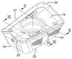
도 1 은 본 발명의 제 1 실시형태에 따른 절삭 인서트 및 스퀘어 숄더 밀링용 공구의 사시도이다.
도 2 는 도 1 의 절삭 인서트를 상방으로부터 비스듬히 바라본 확대 사시도이다.
도 3 은 도 2 의 절삭 인서트를 하방으로부터 비스듬히 바라본 사시도이다.
도 4 및 도 5 는, 각각, 도 2 의 절삭 인서트의 선 Ⅳ-Ⅳ 및 선 Ⅴ-Ⅴ 를 따른 단면도이다.
도 6 은 도 2 의 인서트를 그의 주 측면의 측면도로 보여준다.
도 7 은 도 2 의 인서트를 그의 부 측면의 측면도로 보여준다.
도 8 은 도 2 의 인서트의 저면도이다.
도 9 는 본 발명의 제 2 실시형태에 따른 인서트의 사시도이다.
도 10 은 도 9 에 따른 인서트가 포켓에 고정되어 있는 본 발명에 따른 밀링 절삭 공구의 도 1 에 대응하는 도면이다.1 is a perspective view of a cutting insert and a tool for square shoulder milling according to a first embodiment of the present invention;
FIG. 2 is an enlarged perspective view of the cutting insert of FIG. 1 as viewed obliquely from above;
3 is a perspective view of the cutting insert of FIG. 2 as viewed obliquely from below;
4 and 5 are sectional views taken along the line IV-IV and the line V-V of the cutting insert of FIG. 2 , respectively.
6 shows the insert of FIG. 2 in a side view on its main side;
7 shows the insert of FIG. 2 in a side view in a minor side thereof;
8 is a bottom view of the insert of FIG. 2 ;
9 is a perspective view of an insert according to a second embodiment of the present invention;
FIG. 10 is a view corresponding to FIG. 1 of a milling-cutting tool according to the invention in which the insert according to FIG. 9 is secured in a pocket;
본 발명의 일 실시형태에 따른 스퀘어 숄더 밀링용 밀링 절삭 공구 (1) 가 도 1 에 도시되어 있다. 공구는 포켓에 해제가능하게 고정된 본 발명에 따른 절삭 인서트 (4) 를 각각 수용하기 위한 2 개의 시트 또는 포켓 (3) 을 갖는 공구 보디 (2) 를 구비한다. 공구 보디는 원통형 기본 형상을 갖는 엔드 밀의 형태이지만, 공구 보디는 예를 들어 숄더 정면 밀 (shoulder face mill) 의 형태와 같은 다른 형상을 가질 수도 있다. 포켓의 구조를 보여주기 위해, 절삭 인서트 (4) 가 포켓 (3) 으로부터 제거되어 있다. 공구 보디 (2) 는 전방 단부 (5) 및 후방 단부 (6) 를 포함하고, 이들 단부 사이에는 중심 회전 축선 (C) 이 연장되며, 이 축선 주위에서 공구가 회전 방향 (R) 으로 회전가능하다. 포켓들 (3) 은 공구 보디의 전방 단부 (5) 와 후방 단부 (6) 사이에 연장되는 엔벨로프면 (7) 과 전방 단부 사이의 전이부에 형성된다.A
인서트 포켓 (3) 은 평평한 베이스 (10) 를 대체로 가로지르는 인접한 측벽 (8) 과 후방 벽 (9) 을 포함한다. 측벽 (8) 에는, 아래에서 더 상세하게 설명되는, 베이스 (10) 의 법선과 상이한 각도를 형성하는 전방 반경방향 접촉면 (11) 과 후방 반경방향 접촉면 (12) 의 형태로 상기 회전 축선 (C) 의 방향을 따라 연속적으로 배열된 2 개의 대체로 편평한 비공면의 반경방향 접촉면들이 제공된다. 또한, 포켓 (3) 의 후방벽 (9) 은 상기 포켓 내에 수용된 인서트 (4) 에 대해 축선방향 지지부를 형성하도록 구성된 대체로 편평한 축선방향 접촉면 (13) 을 포함하고, 상기 인서트에 대한 반경방향 지지부는 반경방향 접촉면들 (11, 12) 에 의해 형성된다.The
이제, 본 발명의 제 1 실시형태에 따른 스퀘어 숄더 밀링용 절삭 인서트 (4) 가 도 2 내지 도 8 을 동시에 참조하면서 설명될 것이다. 절삭 인서트는 전형적으로 내마모성 코팅을 포함하는 초경합금으로 제조될 수 있다. 절삭 인서트는 상면 (14), 저면 (15), 및 이들 사이에 연장되고 2 쌍의 대향 측면, 즉 2 개의 대향하는 주 측면 (16, 17) 및 2 개의 대향하는 부 측면 (18, 19) 에 의해 형성된 주변 측면을 포함한다. 주 측면에는 상면과 개별 주 측면의 교차부에 2 개의 대향 주 절삭날 (20, 21) 이 제공되는 반면, 부 측면에는 상면과 개별 부 측면의 교차부에 2 개의 대향 와이퍼 에지 (22) 가 제공된다. 각각의 개별 와이퍼 에지 (22) 는 코너 에지를 통해 개별 측면의 일 단부에서 관련된 주 절삭날 (20, 21) 에 연결된다.Now, a cutting
2 개의 주 측면 (16, 17) 각각은 개별 주 절삭날 (20, 21) 의 연장 방향에 대해 연속적으로 배열된 2 개의 대체로 평평한 비공면의 반경방향 지지면 (23-26) 을 포함한다. 이 반경방향 지지면들은 인서트의 저면 (15) 의 법선 (N) 과 상이한 각도를 형성한다. 이는 개별 주 절삭날 (20) 과 관련된 와이퍼 에지에 가장 가까운 반경방향 지지면 (23) 에 의해 형성되는 각도 (α) 및 상기 와이퍼 에지에 대해 가장 먼 반경방향 지지면 (24) 에 의해 형성되는 각도 (β) 를 보여주는 도 4 및 도 5 에 도시되어 있다. 지지면 (23) 에 의해 형성되는 각도 (α) 가 지지면 (24) 에 의해 형성되는 각도 (β) 보다 작고, 즉 18°에 대해 11°인 것으로 제시되고, 이는 절삭날 (20) 이 비작동 상태에 있는 때에 반경방향 지지면 (23) 이 더 양호한 반경방향 지지부를 제공할 것임을 의미하고, 이는 각도 α 가 더 큰 경우보다 상기 지지면 (23) 의 상한이 낮게 위치될 수도 있음을 의미한다. 이는 정확하게 주 절삭날에서의 힘이 그의 작동 밀링 상태에서 가장 높을 곳인 주 절삭날 (20) 로부터 지지면 (23) 이 더 멀리 이동될 수도 있음을 의미한다. 지지면 (24) 의 더 큰 각도 (β) 는 기계가공된 재료 조각과의 충돌 위험을 방지하고, 쌍방의 각도 α 및 β 는 개별 위치에서 충분한 클리어런스를 제공한다.Each of the two
저면 (15) 에 대해 가장 먼 반경방향 지지면 (23, 24) 의 한계를 형성하는 상부 경계 (27) 는, 저면에 대한 이 경계의 거리가 와이퍼 에지의 관련된 주 절삭날에 연결된 와이퍼 에지 (22) 를 향한 개별 주 절삭날 (20) 의 연장 방향으로 증가하도록 저면에 대해 경사져 있다는 것이 도 6 에 나타나 있다. 상부 경계 (27) 의 이러한 경사가 반경방향 지지면 (24) 에 대해 5.8°이고 와이퍼 에지 (22) 에 가장 가까운 반경방향 지지면 (23) 에 대해 4.3°인 것이 나타나 있다. 이러한 경사는 저면 (15) 에 대한 더 큰 경사를 갖는 주 절삭날을 설계할 수 있게 하여, 절삭 프로세스를 향상시키고 이로써 획득되는 숄더 벽의 품질을 향상시킨다. 이는 또한, 그것의 상부 지지선이 더 높게, 즉 바닥 (15) 으로부터 더 멀리 이동될 것이므로, 반경방향 힘이 반경방향 지지면 (23) 에 의해 더 양호하게 지탱된다는 것을 의미한다. 이는, 절삭날에서의 힘이 또한 증가하고 그러면 더 높은 위치에서 지지부를 갖기에 더 좋으므로, 절삭 깊이가 증가할 때 특히 유리하다.The
도 7 은 인서트의 각각의 부 측면 (18) 에, 이 부 측면의 대향 단부 (30) 보다 와이퍼 에지를 갖는 이 부 측면의 단부 (29) 에 대해 더 멀리 위치되는 축선방향 지지면 (28) 이 제공되는 방법을 보여준다.7 shows that on each
개별 주 절삭날 (20, 21) 과 관련된 상기 와이퍼 에지 (22) 에 대해 가장 먼 각 반경방향 지지면 (24, 25) 은, 관련된 와이퍼 에지로부터 멀어지는 개별 주 절삭날의 연장 방향에서 보았을 때, 인서트의 길이방향 대칭 평면 (S) 을 향해 경사져 있다. 이는, 저면 (15) 에 대해 수직으로 연장되며 인서트를 동일 부분들로 분할하는 대칭 평면 (S) 에 대해 경사가 단지 1.5°이지만, 도 8 에서 보았을 때 이해된다. 이 경사는 릴리프가 가장 중요한 곳인 지지면 (24, 25) 의 단부 (31, 32) 에서 그러한 릴리프를 최적화한다. 또한, 개별 와이퍼 에지 (22) 에 가장 가까운 주 측면의 각 반경방향 지지면 (23, 26) 은 관련된 와이퍼 에지를 향한 개별 상기 주 절삭날의 연장 방향에서 보았을 때 상기 대칭 평면 (S) 을 향해 경사져 있다. 이 경사는 여기서 단지 0.3°이고, 또한 개별 와이퍼 에지에 가까운 릴리프에 긍정적으로 영향을 미친다.Each
각각의 주 절삭날 (20, 21) 은 도 8 에서와 같이 저면 (15) 에 대해 수직으로 보았을 때 볼록한 연장부를 구비함으로써 약간의 캠버를 갖는다. 그러한 캠버의 결과는 위에서 더 설명되어 있다.Each
인서트 포켓의 대응하는 접촉면에 대해 맞닿을 상이한 지지면의 부분 (33-35) 이 격자 패턴으로 표시되어 있다. 공구의 인서트 포켓 (3) 의 접촉면 (11-13) 은 인서트의 저면에 대한 인서트의 지지면 (23-26, 28) 의 한계를 형성하는 대응 상부 경계 (27) 의 거리보다 작은 이 베이스까지의 거리에 포켓의 베이스 (10) 에 대해 가장 먼 지지면의 한계를 형성하는 경계를 갖고, 이는 접촉면 (11, 12, 13) 이 인서트의 개별 지지면의 상한 위에서 인서트에 맞닿지 않는 것을 보장할 것이다. 인서트 포켓의 접촉면 (11, 12, 13) 은 그의 저면 (15) 의 법선에 대한 인서트의 대응 지지면보다 베이스 (3) 의 법선에 대한 더 작은 각도를 또한 형성할 것이다. 이는, 포켓의 전방 반경방향 접촉면 (11) 이 상기 법선에 대해 18°미만의 각도를 형성하는 반면 후방 반경방향 접촉면 (12) 이 11°미만의 상기 법선에 대한 각도를 형성할 것임을 의미한다. 이는 인서트의 지지면과 인서트 포켓의 접촉면이 상부 지지선 (36-38) 에 따라 인접하는 것 (도 6 및 도 7 참조) 을 보장한다.The portions 33-35 of the different bearing surfaces which will abut against the corresponding contact surfaces of the insert pockets are marked in a grid pattern. The contact surface 11-13 of the
더욱이, 포켓 (3) 의 베이스 (10) 는 인서트 (4) 의 관통구멍 (41) 에 대해 약간 오프셋된 위치된 나사 (40) 를 수용하기 위한 나사 구멍 (39) 을 가져서, 나사가 조여지고 인서트의 저면 (15) 이 포켓 (3) 의 베이스 (10) 에 대해 가압되는 때에 포켓의 접촉 표면에 대해 프리텐션 하에 맞닿도록 나사 (40) 가 인서트의 지지면을 강제할 수 있다.Moreover, the
도 9 는 본 발명의 제 2 실시형태에 따른 절삭 인서트 (4) 를 도시하는데, 이는 제 1 실시형태에서와 같이 연속적으로 만곡된 중심 전이면 (43) 대신에 리세스 (42) 에 의한 주 측면에서의 2 개의 지지면 (23, 24) 의 분리에 의해 도 1 내지 도 8 에 도시된 제 1 실시형태에 따른 절삭 인서트와 상이하고, 두 실시형태에 대해 동일한 도면 부호가 사용되었다. 리세스 (42) 는, 인서트 포켓의 임의의 부분에서의 논의되는 주 측면의 중앙 부분의 인접이 발생하지 않고 이로써 잘못된 인접이 중앙 부분으로부터 2 개의 지지면 (23, 24) 으로 분배되거나 또는 더욱 방지되는 것을 또한 보장할 수도 있다. 제 1 실시형태에 따른 절삭 인서트의 경우, 중앙 표면 (43) 의 그러한 인접을 방지하기 위해 공구의 인서트 포켓에 리세스 (44) (도 1 참조) 가 제공될 수도 있다.9 shows a cutting
도 10 은 제 2 실시형태에 따른 인서트의 형태의 본 발명에 따른 인서트가 공구 보디 (2) 에 대해 그의 인서트 포켓 (3) 에 해재가능하게 고정되는 방법을 보여준다. 관통구멍 (41) 에 대한 나사 구멍 (39) 의 상기한 오프셋 덕분에, 반경방향 지지면 (25, 26) 및 부 측 축선방향 지지면 (35) 이 프리텐션 하에서 인서트 포켓 내에서 접촉면 (11-13) 에 대해 강제될 것이고, 지지면 (23-26) 의 지지선 (36, 37), 특히 지지선 (36) 의 높은 위치 덕분에, 인서트 포켓의 베이스 (3) 로부터 인서트의 저면 (15) 의 들어올림이 효과적으로 상쇄될 것이므로, 인서트 포켓의 안정적인 미리 결정된 고정 위치에 인서트가 수용되는 것이 보장된다.FIG. 10 shows how an insert according to the invention in the form of an insert according to a second embodiment is releasably fastened relative to the
물론, 본 발명은 전술한 실시형태들로 한정되지 않으며, 그 변형예에 대한 많은 가능성이, 첨부된 청구항에서 규정되는 본 발명의 범위를 벗어나지 않으면서 본 기술분야의 당업자에게 명백할 것이다.Of course, the present invention is not limited to the embodiments described above, and many possibilities for modifications thereof will be apparent to those skilled in the art without departing from the scope of the invention as defined in the appended claims.
본 발명에 따른 절삭 인서트는 2 개의 대향 주 절삭날이 제공된 2 쌍의 대향 측면을 가질 수도 있어서, 인서트는 4 개의 인덱스 위치들 사이에서 인덱싱될 수도 있다. 그러면, 인서트의 그러한 각 측면의 2 개의 지지면은 인덱스 위치들 중의 하나에서 반경방향 지지부로서 기능하고, 다른 하나에서 축선방향 지지부로서 기능할 것이다.A cutting insert according to the invention may have two pairs of opposite sides provided with two opposed main cutting edges, such that the insert may be indexed between the four index positions. The two bearing surfaces of each such side of the insert will then function as radial supports in one of the index positions and as axial supports in the other.
Claims (21)
상기 주변 측면은 2 쌍의 대향 측면들 (16-19) 을 포함하고, 상기 2 쌍의 대향 측면들 중의 적어도 제 1 쌍의 대향 측면들 (16, 17) 에는 상기 상면과 개별 측면의 교차부에 2 개의 대향하는 주 절삭날들 (20, 21) 이 제공되고, 상기 2 쌍의 대향 측면들 중의 제 2 쌍의 대향 측면들 (18, 19) 에는 상기 상면과 개별 측면의 교차부에 2 개의 대향하는 와이퍼 에지들 (22) 이 제공되고,
각각의 개별 와이퍼 에지 (22) 는 개별 측면의 일 단부에서 상기 개별 와이퍼 에지의 관련된 주 절삭날 (20, 21) 에 연결되고
상기 적어도 제 1 쌍의 대향 측면들인 상기 대향 측면들 (16, 17) 의 각각은, 개별적인 상기 주 절삭날의 연장 방향에 대해 연속적으로 배치되고 상기 저면 (15) 의 법선 (N) 과 상이한 각도들 (α, β) 을 형성하는 2 개의 대체로 평평한 비공면의 (non-coplanar) 지지면들 (23-26) 을 포함하고,
상기 저면 (15) 에 대해 가장 먼 각각의 상기 측면 (16, 17) 의 상기 지지면들 (23-26) 의 한계를 형성하는 상부 경계 (27) 는, 상기 저면에 대한 상기 상부 경계의 거리가 상기 와이퍼 에지의 관련된 주 절삭날에 연결된 상기 와이퍼 에지 (22) 를 향한 상기 주 절삭날 (20, 21) 의 연장 방향으로 증가하도록, 상기 저면에 대해 경사지는, 스퀘어 숄더 밀링용 절삭 인서트.A cutting insert for square shoulder milling comprising a top surface (14), a bottom surface (15), and a peripheral side extending therebetween, the cutting insert comprising:
The peripheral side includes two pairs of opposing sides 16-19, at least a first pair of opposing sides 16, 17 of the two pairs of opposite sides, at the intersection of the upper surface and the respective side surface. Two opposing main cutting edges 20 , 21 are provided, the second pair of opposing sides 18 , 19 of the two pairs of opposing sides having two opposing edges at the intersection of the upper face and the respective side face wiper edges 22 are provided,
Each individual wiper edge 22 is connected at one end of a respective side to an associated main cutting edge 20 , 21 of said individual wiper edge and
Each of the opposite sides 16 , 17 , which is the at least first pair of opposite sides, is arranged continuously with respect to the extension direction of the respective main cutting edge and is at different angles from the normal N of the bottom surface 15 . two generally flat non-coplanar bearing surfaces 23-26 forming (α, β),
The upper boundary 27 defining the limit of the support surfaces 23-26 of each of the side faces 16 , 17 furthest to the bottom surface 15 is such that the distance of the upper boundary to the bottom surface is A cutting insert for square shoulder milling, which is inclined with respect to the bottom surface so as to increase in the direction of extension of the main cutting edge (20, 21) towards the wiper edge (22) connected to the associated main cutting edge of the wiper edge.
상기 저면 (15) 에 대한 상기 상부 경계 (27) 의 경사가 2°- 10°, 3°- 7°또는 4°- 6°인 것을 특징으로 하는, 스퀘어 숄더 밀링용 절삭 인서트.The method of claim 1,
Cutting insert for square shoulder milling, characterized in that the inclination of the upper boundary (27) with respect to the bottom surface (15) is 2°-10°, 3°-7° or 4°-6°.
상기 저면 (15) 에 대한 상기 상부 경계 (27) 의 경사는 상기 와이퍼 에지에 더 가까운 개별 지지면 (23, 26) 의 경우보다 개별 와이퍼 에지 (22) 에 대해 가장 먼 각각의 상기 지지면 (24, 25) 의 경우 더 큰, 예컨대 1°- 4°또는 1°- 2°더 큰 것을 특징으로 하는, 스퀘어 숄더 밀링용 절삭 인서트.The method of claim 1,
The inclination of the upper boundary 27 with respect to the bottom surface 15 is such that each of the bearing surfaces 24 furthest to the respective wiper edge 22 is greater than in the case of the individual bearing surfaces 23 , 26 closer to the wiper edge. , 25) larger, for example 1°-4° or 1°-2° larger, cutting insert for square shoulder milling.
개별 주 절삭날과 관련된 상기 와이퍼 에지 (22) 에 대해 가장 먼 주 절삭날 (20, 21) 이 제공된 측면들의 각각의 상기 지지면 (24, 25) 은, 상기 와이퍼 에지에 더 가까운 개별 지지면 (23, 26) 보다 상기 저면의 법선과 더 큰 각도 (β) 를 형성하는 것을 특징으로 하는, 스퀘어 숄더 밀링용 절삭 인서트.The method of claim 1,
The respective bearing surfaces 24 , 25 of the sides provided with the main cutting edge 20 , 21 furthest relative to the wiper edge 22 in relation to the respective main cutting edge have an individual bearing surface closer to the wiper edge ( 23, 26) A cutting insert for square shoulder milling, characterized in that it forms an angle (β) larger than the normal of the bottom surface.
상기 지지면들 (23-26) 은 상기 저면 (15) 의 법선 (N) 과 8°초과 또는 10°초과의 각도들 (α, β) 을 형성하는 것을 특징으로 하는, 스퀘어 숄더 밀링용 절삭 인서트.The method of claim 1,
Cutting insert for square shoulder milling, characterized in that the bearing surfaces (23-26) form angles (α, β) of more than 8° or more than 10° with the normal (N) of the bottom surface (15) .
개별 주 절삭날과 관련된 와이퍼 에지 (22) 에 대해 가장 가까운 주 절삭날 (20, 21) 이 제공된 측면들의 각각의 상기 지지면 (23, 26) 은 상기 저면 (15) 의 법선 (N) 과 15°미만 또는 12°미만의 각도 (α) 를 형성하는 것을 특징으로 하는, 스퀘어 숄더 밀링용 절삭 인서트.The method of claim 1,
The bearing surfaces 23 , 26 of each of the sides provided with the main cutting edge 20 , 21 closest to the wiper edge 22 associated with the respective main cutting edge are connected to the normal N of the bottom surface 15 and 15 Cutting insert for square shoulder milling, characterized in that it forms an angle (α) less than ° or less than 12 °.
개별 주 절삭날과 관련된 상기 와이퍼 에지 (22) 에 대해 가장 먼 주 절삭날 (20, 21) 이 제공된 측면들의 각각의 상기 지지면 (24, 25) 은 상기 저면 (15) 의 법선 (N) 과 15°이상 또는 15°- 23°또는 17°- 20°의 각도 (β) 를 형성하는 것을 특징으로 하는, 스퀘어 숄더 밀링용 절삭 인서트.The method of claim 1,
The bearing surfaces 24 , 25 of each of the sides provided with the main cutting edge 20 , 21 furthest relative to the wiper edge 22 in relation to the respective main cutting edge are connected to the normal N of the bottom surface 15 and Cutting inserts for square shoulder milling, characterized in that they form an angle (β) of more than 15° or 15°- 23° or 17°-20°.
상기 지지면들 (23-26) 모두는 상기 저면 (15) 까지 연장되는 것을 특징으로 하는, 스퀘어 숄더 밀링용 절삭 인서트.The method of claim 1,
Cutting insert for square shoulder milling, characterized in that both of the bearing surfaces (23-26) extend to the bottom surface (15).
개별 주 절삭날과 관련된 상기 와이퍼 에지 (22) 에 대해 가장 먼 주 절삭날 (20, 21) 이 제공된 측면들의 각각의 상기 지지면 (24, 25) 은, 그의 관련된 와이퍼 에지로부터 멀어지는 개별적인 상기 주 절삭날의 연장 방향에서 보았을 때, 상기 인서트의 길이방향 대칭 평면 (S) 을 향해 경사져 있는 것을 특징으로 하는, 스퀘어 숄더 밀링용 절삭 인서트.The method of claim 1,
Each of the bearing surfaces 24 , 25 of the sides provided with the main cutting edge 20 , 21 furthest to the wiper edge 22 associated with the respective main cutting edge has a respective said main cutting edge away from its associated wiper edge. A cutting insert for square shoulder milling, characterized in that it is inclined toward the longitudinal symmetry plane (S) of the insert when viewed in the extension direction of the blade.
상기 대칭 평면 (S) 을 향해 경사진 각각의 상기 지지면 (24, 25) 은 상기 대칭 평면에 대해 1°- 4°또는 1°- 2°의 각도로 경사져 있는 것을 특징으로 하는, 스퀘어 숄더 밀링용 절삭 인서트.10. The method of claim 9,
Square shoulder milling, characterized in that each of the bearing surfaces (24, 25) inclined towards the plane of symmetry (S) is inclined at an angle of 1°-4° or 1°-2° with respect to the plane of symmetry. for cutting inserts.
상기 와이퍼 에지 (22) 에 가장 가까운 주 절삭날 (20, 21) 이 제공된 측면들의 각각의 상기 지지면 (23, 26) 은, 그의 관련된 와이퍼 에지를 향하는 개별적인 상기 주 절삭날의 연장 방향에서 보았을 때, 상기 대칭 평면 (S) 을 향해 또한 경사져 있는 것을 특징으로 하는, 스퀘어 숄더 밀링용 절삭 인서트.10. The method of claim 9,
The bearing surface 23 , 26 of each of the sides provided with the main cutting edge 20 , 21 closest to the wiper edge 22 , when viewed in the direction of extension of the respective main cutting edge towards its associated wiper edge, is , A cutting insert for square shoulder milling, characterized in that it is also inclined towards the plane of symmetry (S).
상기 2 쌍의 대향 측면들 중의 단지 하나의 대향 측면 (16, 17) 에 2 개의 상기 대향하는 주 절삭날들 (20, 21) 이 제공되고, 이 2 개의 측면들 (16, 17) 은 주 측면들을 형성하고, 다른 2 개의 측면들 (18, 19) 은 부 측면들을 형성하고, 각각의 부 측면이 적어도 하나의 대체로 평평한 지지면 (28) 을 포함하는 것을 특징으로 하는, 스퀘어 숄더 밀링용 절삭 인서트.The method of claim 1,
Only one of the two pairs of opposing sides is provided with two opposing main cutting edges 20 , 21 on one opposing side 16 , 17 , these two sides 16 , 17 defining the main sides and the other two sides (18, 19) form minor sides, each minor side comprising at least one generally flat bearing surface (28).
각각의 상기 부 측면 (18, 19) 의 지지면 (28) 은 와이퍼 에지 (22) 를 갖는 상기 부 측면의 단부 (29) 에 대해 이 부 측면의 반대편 단부 (30) 보다 더 멀리 위치되는 것을 특징으로 하는, 스퀘어 숄더 밀링용 절삭 인서트.13. The method of claim 12,
The bearing surface (28) of each said minor side (18, 19) is positioned further than the opposite end (30) of this minor side with respect to the end (29) of said minor side with a wiper edge (22) cutting inserts for square shoulder milling.
각각의 상기 주 절삭날 (20, 21) 은 상기 저면 (15) 에 대해 수직으로 보았을 때 볼록한 연장부를 구비함으로써 약간의 캠버 (slight camber) 를 갖는 것을 특징으로 하는, 스퀘어 숄더 밀링용 절삭 인서트.The method of claim 1,
Cutting insert for square shoulder milling, characterized in that each of said main cutting edges (20, 21) has a slight camber by having a convex extension when viewed perpendicular to said bottom surface (15).
제 1 항 내지 제 14 항 중 어느 한 항에 따른 적어도 하나의 절삭 인서트 (4), 및
전방 단부 (5) 와 후방 단부 (6) 및 적어도 하나의 인서트 포켓 (3) 을 구비하는 공구 보디 (2) 로서, 상기 전방 단부와 상기 후방 단부 사이에 중심 회전 축선 (C) 이 연장되고, 상기 회전 축선 주위에서 공구가 회전 방향 (R) 으로 회전가능하고, 상기 인서트 포켓은 상기 공구 보디의 전방 단부와 후방 단부 사이에 연장되는 엔벨로프면 (7) 과 상기 전방 단부 사이의 전이부에 형성되는, 상기 공구 보디 (2)
를 포함하고,
상기 인서트 포켓 (3) 은 베이스 (10) 를 대체로 가로지르는 인접한 측벽 (8) 및 후방 벽 (9) 을 포함하고, 상기 측벽 (8) 에는, 상기 베이스 (10) 의 법선과 상이한 각도들을 형성하며 각각 상기 와이퍼 에지 (22) 에 대해 가장 먼 지지면 (24, 25) 과 상기 와이퍼 에지에 대해 가장 가까운 지지면 (23, 26) 을 위한 지지부를 형성하도록 구성된 전방 반경방향 접촉면 (11) 과 후방 반경방향 접촉면 (12) 의 형태로 상기 회전 축선 (C) 의 방향을 따라 연속적으로 배치되는 2 개의 대체로 평평한 비공면의 반경방향 접촉면들 (11, 12) 이 제공되고,
상기 밀링 절삭 공구는 상기 포켓 (3) 의 후방 및 전방 반경방향 접촉면들 (11, 12) 에 대해 2 개의 인서트 지지면들 (23-26) 을 가압하면서 상기 포켓 (3) 에 상기 인서트 (4) 를 고정시키도록 구성된 체결 수단 (39, 40) 을 더 포함하는, 밀링 절삭 공구.A milling cutting tool comprising:
at least one cutting insert (4) according to any one of the preceding claims, and
A tool body (2) having a front end (5) and a rear end (6) and at least one insert pocket (3), the central axis of rotation (C) extending between the front end and the rear end, the the tool is rotatable in a direction of rotation R about an axis of rotation, wherein the insert pocket is formed at a transition between the front end and an envelope surface (7) extending between the front and rear ends of the tool body; the tool body (2)
including,
The insert pocket (3) comprises an adjacent side wall (8) and a rear wall (9) generally transverse to the base (10), the side wall (8) forming angles different from the normal of the base (10), A front radial contact surface 11 and a rear radius configured to form supports for the support surfaces 24, 25 furthest to the wiper edge 22 and support surfaces 23, 26 closest to the wiper edge, respectively In the form of a directional contact surface (12) two generally flat, non-coplanar, radial contact surfaces (11, 12) are provided which are arranged successively along the direction of the rotation axis (C),
The milling cutting tool presses the insert (4) into the pocket (3) while pressing the two insert bearing surfaces (23-26) against the rear and front radial contact surfaces (11, 12) of the pocket (3). and fastening means (39, 40) configured to secure the milling cutting tool.
상기 전방 반경방향 접촉면 (11) 및 상기 후방 반경방향 접촉면 (12) 은, 상기 저면 (15) 에 대한 이 저면에 대해 가장 먼 각각의 상기 인서트 측면의 상기 지지면들 (23-26) 의 한계를 형성하는 대응 상부 경계 (27) 의 거리 미만인, 예컨대 후자의 거리의 80% - 95% 인 상기 베이스에 대한 거리에서 상기 베이스 (10) 에 대한 가장 먼 이들 접촉면의 한계를 형성하는 상부 경계를 구비하는 것을 특징으로 하는, 밀링 절삭 공구.16. The method of claim 15,
The front radial contact surface 11 and the rear radial contact surface 12 delimit the support surfaces 23 - 26 of the respective insert side furthest to this bottom surface to the bottom surface 15 . having an upper boundary defining the limits of these contact surfaces furthest to the base 10 at a distance to the base less than the distance of the corresponding upper boundary 27 forming it, for example 80% - 95% of the distance of the latter A milling cutting tool, characterized in that.
상기 인서트 포켓 (3) 의 상기 전방 반경방향 접촉면 (11) 및 상기 후방 반경방향 접촉면 (12) 은, 상기 인서트 저면 (15) 의 법선 (N) 과 그에 대해 가압되는 상기 인서트 지지면 (23-26) 에 의해 형성되는 각도 (α, β) 보다 더 작은 각도, 그 각도보다 0.5°이상 또는 0.5°- 2°더 작은 각도를 상기 베이스 (10) 의 법선과 형성하는 것을 특징으로 하는, 밀링 절삭 공구.16. The method of claim 15,
The front radial contact surface 11 and the rear radial contact surface 12 of the insert pocket 3 are formed between the normal N of the insert bottom surface 15 and the insert support surface 23-26 pressed against it. A milling cutting tool, characterized in that it forms with the normal of the base (10) an angle smaller than the angle (α, β) formed by ), 0.5° or more or 0.5°-2° smaller than the angle .
상기 2 쌍의 대향 측면들 중의 단지 하나의 대향 측면 (16, 17) 에 2 개의 상기 대향하는 주 절삭날들 (20, 21) 이 제공되고, 이 2 개의 측면들 (16, 17) 은 주 측면들을 형성하고, 다른 2 개의 측면들 (18, 19) 은 부 측면들을 형성하고, 각각의 부 측면이 적어도 하나의 대체로 평평한 지지면 (28) 을 포함하고, 상기 인서트 포켓 (3) 의 상기 후방 벽 (9) 은 상기 인서트 (4) 에 대한 축선방향 지지부를 형성하도록 구성된 대체로 평평한 축선방향 접촉면 (13) 을 포함하는 것을 특징으로 하는, 밀링 절삭 공구.16. The method of claim 15,
Only one of the two pairs of opposing sides is provided with two opposing main cutting edges 20 , 21 on one opposing side 16 , 17 , these two sides 16 , 17 defining the main sides and the other two sides 18 , 19 form minor sides, each minor side comprising at least one generally flat support surface 28 , the rear wall of the insert pocket 3 ( 9) A milling cutting tool, characterized in that it comprises a generally flat axial contact surface (13) configured to form an axial support for the insert (4).
상기 인서트 포켓 (3) 은 나사 (40) 에 의한 포켓에의 고정을 위한 중심 축선방향 관통구멍 (41) 을 구비하는 인서트 (4) 를 수용하도록 구성되고,
상기 포켓의 베이스 (10) 는 상기 인서트의 상기 관통구멍 (41) 에 대해 약간 오프셋되게 위치되는 상기 나사를 수용하기 위한 나사 구멍 (39) 을 구비하여서, 상기 나사가 조여지고 상기 인서트의 저면 (15) 이 상기 포켓의 베이스 (10) 에 대해 가압되는 때에 상기 나사 (40) 가 상기 인서트의 지지면들 (23-26, 28) 을 상기 포켓의 접촉면들 (11-13) 에 대해 프리텐션 하에 맞닿도록 강제할 수 있는 것을 특징으로 하는, 밀링 절삭 공구.16. The method of claim 15,
the insert pocket (3) is configured to receive an insert (4) having a central axial through-hole (41) for fastening to the pocket by means of a screw (40);
The base (10) of the pocket has a screw hole (39) for receiving the screw positioned slightly offset relative to the through hole (41) of the insert, so that the screw is tightened and the bottom face (15) of the insert is tightened. ) is pressed against the base 10 of the pocket, the screw 40 abuts the bearing surfaces 23-26, 28 of the insert under pretension against the contact surfaces 11-13 of the pocket. A milling cutting tool, characterized in that it can be forced to do so.
상기 공구 보디 (2) 는 전방 단부 (5) 와 후방 단부 (6) 및 적어도 하나의 인서트 포켓 (3) 을 구비하고,
상기 전방 단부와 상기 후방 단부 사이에 중심 회전 축선 (C) 이 연장되고, 상기 회전 축선 주위에서 상기 공구 보디 (2) 가 회전 방향 (R) 으로 회전하도록 구성되고,
상기 인서트 포켓은 상기 전방 단부와 후방 단부 사이에 연장되는 엔벨로프면 (7) 과 상기 전방 단부 사이의 전이부에 형성되고,
상기 인서트 포켓 (3) 은 베이스 (10) 를 대체로 가로지르는 인접한 측벽 (8) 및 후방 벽 (9) 을 포함하고, 상기 측벽 (8) 에는, 상기 베이스 (10) 의 법선과 상이한 각도들을 형성하며 전방 반경방향 접촉면 (11) 과 후방 반경방향 접촉면 (12) 의 형태로 상기 회전 축선 (C) 의 방향을 따라 연속적으로 배치되는 2 개의 대체로 평평한 비공면의 반경방향 접촉면들 (11, 12) 이 제공되고,
상기 포켓 (3) 에 수용되는 각각의 상기 절삭 인서트의 지지면 (23-26) 을 위한 지지부를 형성하기 위해, 상기 전방 반경방향 접촉면 (11) 과 상기 후방 반경방향 접촉면 (12) 은 상기 베이스 (10) 에 대해 가장 먼 상기 반경방향 접촉면들 (11, 12) 의 한계를 형성하는 상부 경계를 가지고, 상기 상부 경계는, 상기 베이스 (10) 에 대한 상기 상부 경계의 거리가 상기 전방 반경방향 접촉면 (11) 에서 상기 후방 반경방향 접촉면 (12) 으로의 방향으로 증가하도록, 상기 베이스 (10) 에 대해 경사지고,
상기 공구 보디는 상기 포켓 (3) 의 후방 및 전방 반경방향 접촉면들 (11, 12) 에 대해 2 개의 인서트 지지면들 (23-26) 을 가압하면서 상기 포켓 (3) 에 상기 절삭 인서트를 고정시키도록 구성된 체결 수단 (39, 40) 을 더 포함하는 것을 특징으로 하는, 절삭 인서트용 공구 보디.15. A tool body (2) for a cutting insert according to any one of the preceding claims, comprising:
The tool body (2) has a front end (5) and a rear end (6) and at least one insert pocket (3),
A central axis of rotation (C) extends between the front end and the rear end, around which the tool body (2) is configured to rotate in a direction of rotation (R),
the insert pocket is formed at a transition between the front end and an envelope face (7) extending between the front end and the rear end;
The insert pocket (3) comprises an adjacent side wall (8) and a rear wall (9) generally transverse to the base (10), the side wall (8) forming angles different from the normal of the base (10), Two generally flat, non-coplanar radial contact surfaces 11 , 12 are provided which are arranged successively along the direction of the axis of rotation C in the form of a front radial contact surface 11 and a rear radial contact surface 12 . become,
The front radial contact surface 11 and the rear radial contact surface 12 are connected to the base ( 10) with an upper boundary defining the limits of the radial contact surfaces 11, 12 that are furthest to 11) inclined with respect to the base (10) so as to increase in the direction to the rear radial contact surface (12),
The tool body holds the cutting insert in the pocket (3) while pressing the two insert bearing surfaces (23-26) against the rear and front radial contact surfaces (11, 12) of the pocket (3). Tool body for a cutting insert, characterized in that it further comprises fastening means (39, 40) configured to
상기 인서트 포켓 (3) 의 후방 벽 (9) 은 상기 포켓 (3) 에 수용되는 상기 절삭 인서트에 대한 축선방향 지지부를 형성하도록 구성된 대체로 평평한 축선방향 접촉면 (13) 을 포함하는 것을 특징으로 하는, 절삭 인서트용 공구 보디.21. The method of claim 20,
Cutting, characterized in that the rear wall (9) of the insert pocket (3) comprises a generally flat axial contact surface (13) configured to form an axial support for the cutting insert received in the pocket (3) Tool body for inserts.
Applications Claiming Priority (3)
| Application Number | Priority Date | Filing Date | Title |
|---|---|---|---|
| EP14194024.7A EP3023182B1 (en) | 2014-11-20 | 2014-11-20 | A cutting insert for milling square shoulders, a milling cutting tool and a tool body |
| EP14194024.7 | 2014-11-20 | ||
| PCT/EP2015/075396 WO2016078897A1 (en) | 2014-11-20 | 2015-11-02 | A cutting insert and a cutting tool for milling square shoulders |
Publications (2)
| Publication Number | Publication Date |
|---|---|
| KR20170086513A KR20170086513A (en) | 2017-07-26 |
| KR102403100B1 true KR102403100B1 (en) | 2022-05-26 |
Family
ID=51947183
Family Applications (1)
| Application Number | Title | Priority Date | Filing Date |
|---|---|---|---|
| KR1020177013486A Active KR102403100B1 (en) | 2014-11-20 | 2015-11-02 | A cutting insert and a cutting tool for milling square shoulders |
Country Status (6)
| Country | Link |
|---|---|
| US (1) | US10512977B2 (en) |
| EP (1) | EP3023182B1 (en) |
| JP (1) | JP6695336B2 (en) |
| KR (1) | KR102403100B1 (en) |
| CN (1) | CN107000079B (en) |
| WO (1) | WO2016078897A1 (en) |
Families Citing this family (12)
| Publication number | Priority date | Publication date | Assignee | Title |
|---|---|---|---|---|
| CN106029272B (en) * | 2014-02-26 | 2018-10-19 | 株式会社泰珂洛 | Cutting tip and cutting element |
| CN107921559B (en) * | 2015-09-25 | 2019-09-13 | 三菱日立工具株式会社 | Cutting inserts and indexable insert type rotary cutting tools |
| EP3556498B1 (en) * | 2018-04-16 | 2021-02-17 | Seco Tools Ab | Cutting insert and milling tool |
| CN112108697B (en) | 2019-06-20 | 2024-08-06 | 肯纳金属印度有限公司 | Tool holder with pockets for receiving cutting inserts having different clearance angles |
| US20210138563A1 (en) * | 2019-11-13 | 2021-05-13 | Taegutec Ltd. | Cutting insert and cutting tool assembly including same |
| WO2021246283A1 (en) * | 2020-06-03 | 2021-12-09 | 京セラ株式会社 | Cutting insert, cutting tool, and method for manufacturing cut workpiece |
| EP3984672A1 (en) * | 2020-10-13 | 2022-04-20 | Seco Tools Ab | Double-sided cutting insert and milling tool |
| CN114226820A (en) * | 2022-01-12 | 2022-03-25 | 百斯图工具制造有限公司 | A milling insert and milling tool with both rapid feed and square shoulder |
| JP1743975S (en) * | 2022-11-04 | 2023-05-12 | cutting tool holder | |
| JP1743973S (en) * | 2022-11-04 | 2023-05-12 | cutting tool holder | |
| JP1743974S (en) * | 2022-11-04 | 2023-05-12 | cutting tool holder | |
| EP4635660A1 (en) * | 2024-04-18 | 2025-10-22 | Ceratizit Luxembourg Sàrl | Shouldering insert, milling tool and shoulder milling process |
Citations (1)
| Publication number | Priority date | Publication date | Assignee | Title |
|---|---|---|---|---|
| JP2012024924A (en) | 2006-09-29 | 2012-02-09 | Kyocera Corp | Cutting insert, cutting tool using cutting insert and cutting method |
Family Cites Families (13)
| Publication number | Priority date | Publication date | Assignee | Title |
|---|---|---|---|---|
| SE502541C2 (en) * | 1992-02-05 | 1995-11-06 | Sandvik Ab | Chip separating inserts with precise location-determining dimensions, as well as process for its preparation |
| US5810519A (en) * | 1995-03-17 | 1998-09-22 | Kennametal Inc. | Helical cutting insert with offset cutting edges |
| SE514032C2 (en) * | 1998-09-08 | 2000-12-11 | Seco Tools Ab | Tools and cutters for milling |
| US6503028B1 (en) * | 2001-06-15 | 2003-01-07 | Sandvik Aktiebolag | Sintered cutting insert having center hole for clamp screw |
| JP2003260607A (en) * | 2002-03-08 | 2003-09-16 | Hitachi Tool Engineering Ltd | Insert |
| IL150015A (en) * | 2002-06-04 | 2007-06-17 | Amir Satran | Cutting insert and milling cutter |
| US7771142B2 (en) | 2003-05-09 | 2010-08-10 | Kennametal Inc. | Cutting insert with elliptical cutting edge |
| JP4671643B2 (en) * | 2004-08-27 | 2011-04-20 | 京セラ株式会社 | Milling tools |
| CN101522350A (en) * | 2006-09-29 | 2009-09-02 | 京瓷株式会社 | Cutting insert, cutting tool using the same, and cutting method |
| SE530808C2 (en) * | 2007-01-31 | 2008-09-16 | Sandvik Intellectual Property | Tools for chip separating machining, as well as cutting and basic body for this |
| KR101459062B1 (en) * | 2012-06-14 | 2014-11-07 | 한국야금 주식회사 | cutting insert |
| SE536881C2 (en) * | 2013-02-06 | 2014-10-14 | Sandvik Intellectual Property | Device for chip separating machining with support plate |
| CN203843250U (en) * | 2014-04-29 | 2014-09-24 | 成都邦普合金材料有限公司 | Square shoulder milling cutter blade |
-
2014
- 2014-11-20 EP EP14194024.7A patent/EP3023182B1/en active Active
-
2015
- 2015-11-02 KR KR1020177013486A patent/KR102403100B1/en active Active
- 2015-11-02 JP JP2017527228A patent/JP6695336B2/en active Active
- 2015-11-02 WO PCT/EP2015/075396 patent/WO2016078897A1/en not_active Ceased
- 2015-11-02 CN CN201580063019.3A patent/CN107000079B/en active Active
- 2015-11-02 US US15/527,775 patent/US10512977B2/en active Active
Patent Citations (1)
| Publication number | Priority date | Publication date | Assignee | Title |
|---|---|---|---|---|
| JP2012024924A (en) | 2006-09-29 | 2012-02-09 | Kyocera Corp | Cutting insert, cutting tool using cutting insert and cutting method |
Also Published As
| Publication number | Publication date |
|---|---|
| CN107000079B (en) | 2019-05-17 |
| EP3023182A1 (en) | 2016-05-25 |
| US20170320146A1 (en) | 2017-11-09 |
| WO2016078897A1 (en) | 2016-05-26 |
| US10512977B2 (en) | 2019-12-24 |
| JP6695336B2 (en) | 2020-05-20 |
| JP2017535439A (en) | 2017-11-30 |
| CN107000079A (en) | 2017-08-01 |
| EP3023182B1 (en) | 2019-11-06 |
| KR20170086513A (en) | 2017-07-26 |
Similar Documents
| Publication | Publication Date | Title |
|---|---|---|
| KR102403100B1 (en) | A cutting insert and a cutting tool for milling square shoulders | |
| KR101978078B1 (en) | Double-sided cutting insert and milling tool | |
| KR101292441B1 (en) | Tangential cutting insert | |
| US9296054B2 (en) | Indexable cutting insert with a triangular shape | |
| EP2070620B1 (en) | Cutting insert, cutting tool using the same, and cutting method | |
| US9555488B2 (en) | Milling insert | |
| KR101097658B1 (en) | Cutting insert | |
| RU2370349C2 (en) | Cutting plate for face milling and milling tool | |
| US9205499B2 (en) | Cutting insert with finishing and roughing cutting edges | |
| JP6295453B2 (en) | Double-sided milling inserts and milling tools | |
| CN1611316B (en) | Indexable cutting insert, manufacturing method thereof, and cutting tool having such insert | |
| US9776258B2 (en) | Double-sided, trigon cutting insert with rounded minor cutting edge and cutting tool therefor | |
| KR20170058366A (en) | Rotary cutting tool and reversible cutting insert having variable-width minor relief surfaces therefor | |
| EP3338931B1 (en) | Cutting insert and cutting tool | |
| WO2010098345A1 (en) | Cutting insert, cutting tool and method of cutting using the same | |
| WO2010147065A1 (en) | Cutting insert and indexable face milling cutter | |
| RU2744132C2 (en) | Metal-cutting milling machine | |
| CN101522349A (en) | Cutting insert, cutting tool using the same, and cutting method | |
| KR102362021B1 (en) | A cutting tool and a cutting insert for a chip-removing tool | |
| US7476062B2 (en) | Cutting insert with recessed corners | |
| JP5988010B2 (en) | Cutting inserts, tool bodies and cutting tools | |
| CN112313025A (en) | Tangential cutting inserts and milling tools | |
| JP2004195563A (en) | Edge replaceable rotary tool and insert therefor | |
| JP2016187836A (en) | Cutting insert and cutting edge replaceable cutting tool | |
| JP5729027B2 (en) | Cutting insert and cutting edge changeable cutting tool |
Legal Events
| Date | Code | Title | Description |
|---|---|---|---|
| PA0105 | International application |
Patent event date: 20170518 Patent event code: PA01051R01D Comment text: International Patent Application |
|
| PG1501 | Laying open of application | ||
| A201 | Request for examination | ||
| PA0201 | Request for examination |
Patent event code: PA02012R01D Patent event date: 20200901 Comment text: Request for Examination of Application |
|
| E902 | Notification of reason for refusal | ||
| PE0902 | Notice of grounds for rejection |
Comment text: Notification of reason for refusal Patent event date: 20211103 Patent event code: PE09021S01D |
|
| E701 | Decision to grant or registration of patent right | ||
| PE0701 | Decision of registration |
Patent event code: PE07011S01D Comment text: Decision to Grant Registration Patent event date: 20220502 |
|
| GRNT | Written decision to grant | ||
| PR0701 | Registration of establishment |
Comment text: Registration of Establishment Patent event date: 20220524 Patent event code: PR07011E01D |
|
| PR1002 | Payment of registration fee |
Payment date: 20220524 End annual number: 3 Start annual number: 1 |
|
| PG1601 | Publication of registration |