JP2012024922A - Robot - Google Patents
Robot Download PDFInfo
- Publication number
- JP2012024922A JP2012024922A JP2011230666A JP2011230666A JP2012024922A JP 2012024922 A JP2012024922 A JP 2012024922A JP 2011230666 A JP2011230666 A JP 2011230666A JP 2011230666 A JP2011230666 A JP 2011230666A JP 2012024922 A JP2012024922 A JP 2012024922A
- Authority
- JP
- Japan
- Prior art keywords
- movable body
- arm
- elevating
- cable
- flat cable
- Prior art date
- Legal status (The legal status is an assumption and is not a legal conclusion. Google has not performed a legal analysis and makes no representation as to the accuracy of the status listed.)
- Granted
Links
Images


Classifications
-
- B—PERFORMING OPERATIONS; TRANSPORTING
- B25—HAND TOOLS; PORTABLE POWER-DRIVEN TOOLS; MANIPULATORS
- B25J—MANIPULATORS; CHAMBERS PROVIDED WITH MANIPULATION DEVICES
- B25J9/00—Program-controlled manipulators
- B25J9/02—Program-controlled manipulators characterised by movement of the arms, e.g. cartesian coordinate type
- B25J9/023—Cartesian coordinate type
- B25J9/026—Gantry-type
-
- B—PERFORMING OPERATIONS; TRANSPORTING
- B25—HAND TOOLS; PORTABLE POWER-DRIVEN TOOLS; MANIPULATORS
- B25J—MANIPULATORS; CHAMBERS PROVIDED WITH MANIPULATION DEVICES
- B25J19/00—Accessories fitted to manipulators, e.g. for monitoring, for viewing; Safety devices combined with or specially adapted for use in connection with manipulators
- B25J19/0025—Means for supplying energy to the end effector
-
- Y—GENERAL TAGGING OF NEW TECHNOLOGICAL DEVELOPMENTS; GENERAL TAGGING OF CROSS-SECTIONAL TECHNOLOGIES SPANNING OVER SEVERAL SECTIONS OF THE IPC; TECHNICAL SUBJECTS COVERED BY FORMER USPC CROSS-REFERENCE ART COLLECTIONS [XRACs] AND DIGESTS
- Y10—TECHNICAL SUBJECTS COVERED BY FORMER USPC
- Y10T—TECHNICAL SUBJECTS COVERED BY FORMER US CLASSIFICATION
- Y10T408/00—Cutting by use of rotating axially moving tool
- Y10T408/91—Machine frame
-
- Y—GENERAL TAGGING OF NEW TECHNOLOGICAL DEVELOPMENTS; GENERAL TAGGING OF CROSS-SECTIONAL TECHNOLOGIES SPANNING OVER SEVERAL SECTIONS OF THE IPC; TECHNICAL SUBJECTS COVERED BY FORMER USPC CROSS-REFERENCE ART COLLECTIONS [XRACs] AND DIGESTS
- Y10—TECHNICAL SUBJECTS COVERED BY FORMER USPC
- Y10T—TECHNICAL SUBJECTS COVERED BY FORMER US CLASSIFICATION
- Y10T409/00—Gear cutting, milling, or planing
- Y10T409/30—Milling
- Y10T409/30784—Milling including means to adustably position cutter
- Y10T409/307952—Linear adjustment
- Y10T409/308288—Linear adjustment including gantry-type cutter-carrier
-
- Y—GENERAL TAGGING OF NEW TECHNOLOGICAL DEVELOPMENTS; GENERAL TAGGING OF CROSS-SECTIONAL TECHNOLOGIES SPANNING OVER SEVERAL SECTIONS OF THE IPC; TECHNICAL SUBJECTS COVERED BY FORMER USPC CROSS-REFERENCE ART COLLECTIONS [XRACs] AND DIGESTS
- Y10—TECHNICAL SUBJECTS COVERED BY FORMER USPC
- Y10T—TECHNICAL SUBJECTS COVERED BY FORMER US CLASSIFICATION
- Y10T74/00—Machine element or mechanism
- Y10T74/20—Control lever and linkage systems
- Y10T74/20207—Multiple controlling elements for single controlled element
- Y10T74/20341—Power elements as controlling elements
- Y10T74/2036—Pair of power elements
Landscapes
- Engineering & Computer Science (AREA)
- Robotics (AREA)
- Mechanical Engineering (AREA)
- Manipulator (AREA)
- Electric Cable Arrangement Between Relatively Moving Parts (AREA)
Abstract
Description
本発明は、ツールが連結される移動可能な可動体と固定体との間にケーブルが配索されたロボットに関する。 The present invention relates to a robot in which a cable is routed between a movable body and a fixed body to which a tool is connected.
少なくとも平面上の一方向に移動可能な台車を備え、台車上に取付けられたアームが旋回可能なロボットに関する従来技術があった(例えば、特許文献1参照)。これは、アームがワークに処置を施す作業部を有しており、台車が移動した先の位置においてアームを旋回させ、作業部によりワークに処置を施すものである。従って、アームと電源とをつなぐ電力供給ラインおよびコントローラとアームとを接続する信号線を必要としており、電線ケーブルによりアームと固定体とを互いに相対移動可能に接続する必要があった。 There has been a conventional technology related to a robot that includes a cart that can move in at least one direction on a plane and that can turn an arm mounted on the cart (see, for example, Patent Document 1). In this case, the arm has a working unit that applies a treatment to the work, and the arm is turned at a position where the carriage has moved, and the work is given to the work by the working unit. Therefore, a power supply line that connects the arm and the power source and a signal line that connects the controller and the arm are required, and the arm and the fixed body need to be connected to each other so as to be movable relative to each other by an electric cable.
ところで、これまでロボットの固定体と可動体との間をケーブルで接続する場合、通常、ケーブルベア(登録商標)を使用していた。ケーブルベアは合成樹脂材料等により形成された複数のフレームがピンにより屈曲可能に連結され、その内部に複数のケーブルが収容されたものである。これによりケーブルはフレームにより保護されながら可動体の移動により自由に撓むことが可能で、可動体に対して安定して電力の供給あるいは信号の伝達を行うことができた。 By the way, when connecting between the fixed body and movable body of a robot with a cable until now, the cable bear (registered trademark) was normally used. The cable bear is formed by connecting a plurality of frames formed of a synthetic resin material or the like so as to be bent by pins, and housing a plurality of cables therein. As a result, the cable can be freely bent by the movement of the movable body while being protected by the frame, and power can be stably supplied or signals can be transmitted to the movable body.
しかし、ケーブルベアはフレームを有することによりスペースを多くとり、ケーブルが配索された装置の長大化を招いていた。また、固定体と可動体との相対移動に伴いケーブルがフレームと擦れ合い、ケーブルの被覆およびフレームの磨耗粉が発生し、これを除去するための手間が面倒であった。
そこで、上述した従来技術においては、固定体と可動体との接続をフラットケーブルを用いて行っている。フラットケーブルは複数のケーブルが並列の状態で互いを接合したもので、撓み自由とされている。ケーブルベアに代えてフラットケーブルを使用することにより、装置の小型化が可能となり、ケーブルがフレームと擦れ合うことによる磨耗粉の発生も防止することができる。
However, since the cable bear has a frame, it takes a lot of space, which leads to an increase in the length of the device in which the cable is routed. In addition, the cable rubs against the frame as the fixed body and the movable body move relative to each other, and the cable cover and the frame wear powder are generated, which is troublesome to remove.
Therefore, in the above-described conventional technology, the fixed body and the movable body are connected using a flat cable. The flat cable is formed by joining a plurality of cables in parallel and is free to bend. By using a flat cable in place of the cable track, it is possible to reduce the size of the apparatus, and it is possible to prevent the generation of wear powder due to the cable rubbing against the frame.
しかしながら、上記従来技術では、フラットケーブルを導入することで、装置の小型化やケーブルベアの擦れ合いによる磨耗粉発生を抑制できることと引き換えに、フラットケーブルが元々備えている特性であるフレキシビリティ性により、固定体に対し可動体が移動することにより自由に撓むことになる。
その結果、フラットケーブルが撓んだ部分が他の物体に干渉するという事態が発生すると、逆にその場合には、今までのようなケーブルベアによる保護が無くフラットケーブルが剥き出しになっていることが原因で、フラットケーブルが損傷してしまう。
However, in the above prior art, by introducing the flat cable, it is possible to suppress the generation of wear powder due to the downsizing of the device and the friction of the cable bear, and at the same time, due to the flexibility that is a characteristic originally provided by the flat cable. When the movable body moves with respect to the fixed body, it is flexed freely.
As a result, when the part where the flat cable bends interferes with other objects, on the contrary, the flat cable is exposed without being protected by the cable bear as before. Will damage the flat cable.
本発明は、上記事情に鑑みてなされたものであり、その目的は、フラットケーブルを剥き出しで使用しても、他の物体へ干渉することなく、フラットケーブルが損傷しない構造を持つロボットを提供することにある。 The present invention has been made in view of the above circumstances, and an object of the present invention is to provide a robot having a structure in which a flat cable is not damaged without interfering with other objects even when the flat cable is exposed. There is.
本発明の課題を解決するために、請求項1のロボットによれば、ケーブル束体は固定体および上下方向可動体への取付部位の間において下方に垂れ下がっている垂れ下がり部を有し、上下方向可動体が固定体に対して最も上昇した状態において、ケーブル束体の垂れ下がり部は上下方向可動体の下端および固定体の上下方向可動体と接する側の下端よりも上方に位置し、上下方向可動体が下降している下降中状態において、ケーブル束体の垂れ下がり部は上下方向可動体の下端よりも上方に位置することを維持しながら上下方向可動体の下降に合わせて降下し、上下方向可動体が固定体に対して最も下降した状態において、ケーブル束体の垂れ下がり部は上下方向可動体の下端よりも上方に位置する。 In order to solve the problems of the present invention, according to the robot of claim 1, the cable bundle has a hanging part that hangs downward between the fixed body and the attachment portion to the vertically movable body, and the vertical direction. In a state where the movable body is raised most with respect to the fixed body, the hanging portion of the cable bundle is located above the lower end of the vertical movable body and the lower end of the fixed body on the side in contact with the vertical movable body, and is movable in the vertical direction. While the body is descending, the hanging part of the cable bundle is lowered with the descending of the vertically movable body while maintaining the position where the hanging part of the cable bundle is located above the lower end of the vertically movable body, and is movable vertically. In a state where the body is lowered most with respect to the fixed body, the hanging portion of the cable bundle is located above the lower end of the vertically movable body.
これにより、常に、ケーブル束体が上下方向可動体の下端よりも上方にあり、換言すれば、可動体が先に下降し、その後にケーブル束体の撓みが追従していくので、仮にケーブル束体の撓み先に他の物体が存在しても、先に可動体が他の物体に接触することで可動体による他の物体の押し退けが行われるので、後から追従して下降するケーブル束体は他の物体に干渉しない。 As a result, the cable bundle is always above the lower end of the vertically movable body. In other words, the movable body descends first, and then the bending of the cable bundle follows. Even if there is another object at the bending point of the body, the movable body will first push away the other object by contacting the other object, so the cable bundle that follows and descends later Does not interfere with other objects.
このため、ケーブル束体を剥き出しで使用しても、他の物体へ干渉することなく、ケーブル束体が損傷しないようにすることができる。
また、請求項1のロボットによれば、上下方向可動体が固定体に対して最も上昇した状態では、垂れ下がり部のうち最小曲げ部分の曲率半径(以下、曲率半径を「R」とする。)が小さく、垂れ下がり部に大きなストレスが作用するにしても、上下方向可動体が固定体に対して下降している下降中状態、或いは最も下降した状態においては、垂れ下がり部の最小曲げRが、上下方向可動体が固定体に対して最も上昇した状態に比べて大きくなるので、ケーブル束体に対するストレスを緩和することができる。
For this reason, even if it uses a cable bundle body barely, it can prevent a cable bundle body from being damaged, without interfering with another object.
According to the robot of the first aspect, in the state where the vertically movable body is raised most with respect to the fixed body, the radius of curvature of the minimum bent portion of the suspended portion (hereinafter, the radius of curvature is referred to as “R”). Even when a large stress is applied to the hanging part, the minimum bending R of the hanging part is lower in the vertical direction when the vertically movable body is lowered with respect to the fixed body or in the most lowered state. Since the directional movable body becomes larger than the state where the directional movable body is raised most with respect to the fixed body, the stress on the cable bundle can be reduced.
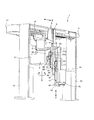
以下、本発明の一実施形態について図面を参照して説明する。図1に示すように、これに限定されることはないが、ロボット1は一対のスタンド2a、2bによって上端のスライド部3が両端から懸架されることにより水平に支持されており、下方に設置されたコンベア(図示せず)により運搬された部品に対して所定の処置を施すことができる。
スライド部3の下面には、長手方向(図2において左右方向)に延びたガイドレール4が取付けられており、ガイドレール4に移動体5が移動可能に係合している。また、スライド部3には直動軸としてのボールねじ(図示せず)が収容されている。スライド部3に内蔵されたボールねじには図示しないナット部材が螺合しており、ナット部材には上述した移動体5が連結されている。図2におけるスライド部3の右端部には直動用モータ6が取付けられ、直動用モータ6の出力軸(図示せず)は前述のボールねじに連結されている。スライド部3の側面に取付けられた電源ボックス7(図3示)には外部からパワーサプライ用ケーブルが導かれ、前述の直動用モータ6へと接続されている。これにより、直動用モータ6を駆動してボールねじを回転させると、スライド部3に対して回転不能であるナット部材がボールねじ上を移動するため、移動体5は図2において左右方向(X軸方向)に移動する。
Hereinafter, an embodiment of the present invention will be described with reference to the drawings. As shown in FIG. 1, although not limited to this, the robot 1 is horizontally supported by a pair of
A guide rail 4 extending in the longitudinal direction (left-right direction in FIG. 2) is attached to the lower surface of the
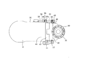
移動体5の下方には、アーム8(本発明の固定体に該当する)が移動体5に対して鉛直なR軸を中心に回転可能に取付けられている(図1示)。移動体5には旋回用モータ9が取り付けられており、旋回用モータ9はケーブルベア10により保護されたパワーサプライ用ケーブルにより電源ボックス7と接続されている。尚、ケーブルベア10は一般的に使用されているものと同様のものであるが、図1および図3において、その外形状は簡素化されて表わされている。旋回用モータ9はパワーサプライ用ケーブルを介して電力が供給されることにより駆動され、アーム8をR軸を中心に水平面内に回転させることができる。
An arm 8 (corresponding to a fixed body of the present invention) is attached to the lower side of the
一方、アーム8は上下方向には不動であり、このアーム8に対して上下方向に移動可能に第1昇降部11が連結され、さらに第1昇降部11に対して上下方向に相対移動可能に第2昇降部12が接続されている(以下、第1昇降部11および第2昇降部12を包括して昇降部という)。これにより、第1昇降部11および第2昇降部12はアーム8に対してテレスコピック(伸縮自在)に形成されており、アーム8とともに水平面内に回転可能となっている。第1昇降部11は本発明の第1可動体に該当し、第2昇降部12は後述する回転軸用モータ30とともに本発明の第2可動体に該当し、また第1昇降部11および第2昇降部12を包括したものが本発明の上下方向可動体に該当する。
On the other hand, the
図5に示すように、第1昇降部11の第1レール部材13はアーム8の上下一対の第1ガイド部材14と係合している。また、第2昇降部12の第2レール部材15は第1昇降部11の上下一対の第2ガイド部材16と係合している。これらにより、アーム8と第1昇降部11および第1昇降部11と第2昇降部12は、互いに上下方向(Z軸方向)に相対移動可能に形成されている。
As shown in FIG. 5, the
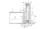
アーム8を形成するアームハウジング17中には昇降用モータ18が設けられており、昇降用モータ18の出力軸19はアームハウジング17に形成された貫通孔20に挿通され、第1昇降部11に形成されたスロット21を貫通した後、先端に固着されたピニオンギヤ22が第2昇降部12に形成されたラック23と噛合している。昇降用モータ18には前述のパワーサプライ用ケーブルが接続されており、これを介して電力を供給することにより昇降用モータ18を駆動すると、ピニオンギヤ22が回転しラック23を介して第2昇降部12を上下動させることができる。
A
アームハウジング17の側端部の上下位置からは一対の係合部24a、24bが突出している。また、第1昇降部11の上端には、アームハウジング17の上部係合部24aと対向し、これに対して上方から係合可能な上部ストッパ部25aが形成されている。また、第1昇降部11の下端には、アームハウジング17の下部係合部24bと対向して、これに対して下方から係合可能な下部ストッパ部25bが形成されている。また、第1昇降部11のストッパ部25a、25bが形成された側と反対側の面には、上下方向の略中央部に停止部26が突出しており、また、下方には係止部27が突出している。
A pair of
一方、第2昇降部12の第1昇降部11と対向した側の上端には、前述した第1昇降部11の停止部26に対して上方から係合可能な位置決め部28が形成されており、下端には第1昇降部11の係止部27に対して下方から係合可能な支承部29が突出している。また、第2昇降部12の第1昇降部11と対向した側と反対側の面の下方には、回転軸用モータ30が取付けられている。回転軸用モータ30の下端部先端には減速機31が形成され、減速機31を介して、ワークを把持する、あるいはワークに穴あけ加工等の処置を施す図示しないツール(本発明において作業部に該当する)が回転軸用モータ30に対し連結可能になっている。尚、上述した直動用モータ6、旋回用モータ9、昇降用モータ18および回転軸用モータ30の作動は、図外の制御装置により制御されている。
On the other hand, a
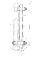
回転軸用モータ30は上述したパワーサプライ用ケーブルに接続されたフラットケーブル(本発明のケーブル束体に該当する)32により電力が供給(電気を授受)されて、ツールを回転駆動することが可能となっている。フラットケーブル32は電線をゴムあるいは樹脂材料等により被覆した一対のケーブル33、34(図4示)を、並列状態にした上で互いに溶着により接合して平板状に形成したものである。図7(a)に示すように、フラットケーブル32はアームハウジング17の第1昇降部11との対向方向(図4において左右方向)に対する側面35から引き出され、側面35に沿って、一旦、上方へと昇った後、第1昇降部11へ近づくように横方向(図4において右方)に移動する。
The
その後、フラットケーブル32は下方へと延びてケーブルクランプ36により、アームハウジング17の側面35に固定されている。ケーブルクランプ36は鋼板あるいは板バネ材をプレス成型して形成されており、図7(a)に示すように、アームハウジング17の側面35にボルト締めされて固定されている。ケーブルクランプ36は切片が鉤状に曲げられることによって形成された一対のクランプ部37a、37bを備えており、フラットケーブル32はこのクランプ部37a、37bに挟持されることにより、アームハウジング17の側面35から所定距離だけ離れて(図4示)、アーム8と第1昇降部11および第2昇降部12との移動方向と平行の方向で、かつ垂れ下がっている部位のある方向からアーム8への方向に保持されている(図2示)。
Thereafter, the
ケーブルクランプ36の上端には水平方向に延びるケーブルガイド38が形成されており、これによりアームハウジング17の側面35から引き出されたフラットケーブル32は水平方向に保持されている。また、ケーブルクランプ36の下端には斜め方向に延びた撓みガイド39(本発明の案内手段に該当する)が形成されており、これにより第2昇降部12が下降した時のフラットケーブル32の撓みを規制している(図1示)。この撓みガイド39の先端部はフラットケーブル32と反対側に折曲形成されている。これは、撓みガイド39の先端部がフラットケーブル32に接触することによる損傷を防止するためである。
A
フラットケーブル32はケーブルクランプ36よりも下方において垂れ下がり、その後、再び上昇して第2昇降部12の側面40(アーム8と第1昇降部11との対向方向に対する側面に相当)に取付けられている。第2昇降部12の回転軸用モータ30の取付面には、ストッパプレート41が固着されている(図1示)。ストッパプレート41は金属板により形成されており、取付ボルト(図示せず)により第2昇降部12に固定されている。ストッパプレート41の側端にはCクランプ部42が形成されており、これにフラットケーブル32が保持されている。Cクランプ部42はストッパプレート41の端片が巻回されて形成されており、フラットケーブル32はこれに挟持されることにより、前述したアームハウジング17に対する場合と同様に、第2昇降部12の側面40から所定距離だけ離れて(図4示)、アーム8と第1昇降部11および第2昇降部12との移動方向と平行の方向で、かつフラットケーブル32の垂れ下がっている部位のある方向から第2昇降部12への方向に固定されている(図2示)。また、アーム8と回転軸用モータ30との間を接続するフラットケーブル32は、各ケーブル33、34がアーム8および第2昇降部12の側面35、40から離れる方向(図4において上方)に並ぶように取付けられている。
The
図1に示すように、Cクランプ部42から第2昇降部12の側面40上を上方へと延びたフラットケーブル32は、ストッパプレート41の上端に形成された折曲部43に係止されることにより下方に向けて折り返されている。折曲部43において折り返されたフラットケーブル32は、ストッパプレート41の回転軸用モータ30側を下降して回転軸用モータ30内に引き込まれている。第2昇降部12の側面40上にあるフラットケーブル32は、ストッパプレート41の縁部44に当接することによって回転軸用モータ30側への撓みが規制されている。
As shown in FIG. 1, the
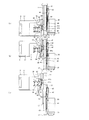
次に、図5乃至図7に基づき、上述した構成による昇降部11、12の作動方法について説明する。図5および図7(a)に示すように、アーム8に対して第1昇降部11および第2昇降部12が最上位置(上死点)にある時、第2昇降部12はラック23が静止した昇降用モータ18のピニオンギヤ22と噛合することにより保持されている。一方、第1昇降部11は係止部27が第2昇降部12の支承部29と係合することにより支持されている。
Next, based on FIG. 5 thru | or FIG. 7, the operating method of the raising / lowering
昇降用モータ18に電力を供給して一方向に駆動すると、出力軸19を介してピニオンギヤ22が回転するため、これと係合したラック23の移動により第2昇降部12が下降する。第2昇降部12の下降により、支承部29により支持されている第1昇降部11も自重により第2昇降部12と一体となって下降する。
昇降用モータ18の駆動により、第1昇降部11および第2昇降部12が所定距離だけ下降して第1昇降部11の上部ストッパ部25aがアームハウジング17の上部係合部24aに当接すると、第1昇降部11はアーム8に固定されてそれ以上は下降しなくなり(図6および図7(b)示)、それ以降、第2昇降部12のみがアーム8および第1昇降部11に対して下降する。
When electric power is supplied to the elevating
When the first elevating
やがて、第2昇降部12の位置決め部28が第1昇降部11の停止部26に上方から係合すると第2昇降部12はそれ以上は下降できなくなるため、制御装置は昇降用モータ18の駆動を停止させる(図6および図7(c)示)。制御装置は第2昇降部12の下降停止による昇降用モータ18の負荷電流の増大を検出して昇降用モータ18の駆動を停止させてもよいし、パルスエンコーダ等により昇降用モータ18の駆動量を検出して昇降用モータ18を停止させてもよい。
Eventually, when the
図6および図7(c)に示したように、第1昇降部11および第2昇降部12がアーム8に対して最も下降した位置(下死点)にある状態から、第1昇降部11および第2昇降部12をアーム8に対して上昇させる場合、昇降用モータ18を前述した場合と逆方向に駆動させると、ピニオンギヤ22の回転によるラック23の移動により、第2昇降部12のみがアーム8および第1昇降部11に対して上昇する。
第2昇降部12の上昇により、支承部29がアーム8に支持された第1昇降部11の係止部27と係合すると、第1昇降部11も第2昇降部12とともに上昇を開始する。やがて、第1昇降部11の下部ストッパ部25bがアームハウジング17の下部係合部24bと係合すると、第1昇降部11および第2昇降部12はそれ以上は上昇できなくなるため、制御装置は昇降用モータ18の駆動を停止させる(図5および図7(a)示)。
As shown in FIGS. 6 and 7C, the first elevating
When the
図7(a)に示すように、フラットケーブル32のアーム8および第2昇降部12への取り付け部の間に位置する下方への垂れ下がり部45は、第1昇降部11および第2昇降部12の下端47、46およびアーム8の第1昇降部11と接する側の下端48よりも上方に位置している。
図7(b)に示すように、第1昇降部11および第2昇降部12が下降している下降中状態において、フラットケーブル32の垂れ下がり部45は第1昇降部11および第2昇降部12の下端47、46よりも上方に位置することを維持しながら第1昇降部11および第2昇降部12の下降に合わせて降下する。このとき、垂れ下がり部45は、曲げ形状からの復元力により撓みガイド39に沿って案内された状態で拡開し、それに伴って最小曲げRが大きくなる。
As shown in FIG. 7A, the downward hanging
As shown in FIG. 7B, the hanging
図7(c)に示すように、第1昇降部11および第2昇降部12がアーム8に対して最も下降した状態において、フラットケーブル32の垂れ下がり部45は、第2昇降部12の下端46よりも上方に位置する。また、図6および図7(c)に示すように、第2昇降部12がアーム8および第1昇降部11に対して最も下降した状態において、フラットケーブル32の垂れ下がり部45は第1昇降部11の下端47よりも上方にある。このとき、垂れ下がり部45は、曲げ形状からの復元力により撓みガイド39に沿って案内された状態でさらに拡開し、最終的には最小曲げRが最大となる。
As shown in FIG. 7C, when the first elevating
本実施形態によれば、第1昇降部11および第2昇降部12がアーム8に対して最も上昇した状態において、フラットケーブル32の垂れ下がり部45は第1昇降部11および第2昇降部12の下端47、46およびアーム8の第1昇降部11と接する側の下端48よりも上方に位置し、昇降部11、12が下降している下降中状態において、フラットケーブル32の垂れ下がり部45は第1昇降部11および第2昇降部12の下端47、46よりも上方に位置することを維持しながら昇降部11、12の下降に合わせて降下し、第1昇降部11および第2昇降部12がアーム8に対して最も下降した状態において、フラットケーブル32の垂れ下がり部45は第1昇降部11および第2昇降部12の下端47、46よりも上方に位置する。
According to the present embodiment, when the first elevating
これにより、常に、フラットケーブル32が第1昇降部11および第2昇降部12の下端47、46よりも上方にあり、換言すれば、昇降部11、12が先に下降し、その後にフラットケーブル32の撓みが追従していくので、仮にフラットケーブル32の撓み先に他の物体が存在しても、先に昇降部11、12が他の物体に接触することで昇降部11、12による他の物体の押し退けが行われるので、後から追従して下降するフラットケーブル32は他の物体に干渉しない。
Thereby, the
このため、フラットケーブル32を剥き出しで使用しても、他の物体へ干渉することなく、フラットケーブル32が損傷しないようにすることができる。
また、フラットケーブル32はアーム8と第2昇降部12との対向方向に対する側面35、40に取付けられ、フラットケーブル32はアーム8および第2昇降部12に取付けられた状態で、双方への取付部位の間がアーム8、第1昇降部11および第2昇降部12と所定距離だけ離れて保持され、フラットケーブル32を形成する各々のケーブル33、34は、アーム8および第2昇降部12の側面35、40から離れる方向に並んでいる。
For this reason, even if the
Further, the
これにより、第1昇降部11あるいは第2昇降部12がアーム8に対して移動すると、平板状のフラットケーブル32はアーム8および第2昇降部12の側面35、40から所定距離だけ離れた状態で垂れ下がり部45の形成される方向(フラットケーブル32が平板として折り曲げられる方向)に撓むため、フラットケーブル32はアーム8、第1昇降部11および第2昇降部12に干渉せず、撓むことにより無理な応力を発生させることもなく、ダメージを受けることがない。
Thereby, when the 1st raising / lowering
また、昇降部11、12は、アーム8に対して上下移動可能に連結された第1昇降部11と、第1昇降部11に対して上下方向に相対移動可能に接続された第2昇降部12により形成され、最上位置から第1昇降部11および第2昇降部12が一体となってアーム8に対して所定距離だけ下降した後、第1昇降部11がアーム8に対して固定された状態で、第2昇降部12のみがアーム8および第1昇降部11に対して下降し、第2昇降部12がアーム8および第1昇降部11に対して最も下降した状態において、フラットケーブル32の垂れ下がり部45は第1昇降部11の下端47よりも上方にある。
これにより、第2昇降部12がアーム8および第1昇降部11に対して下降しても、フラットケーブル32が第1昇降部11の下端47に当接することがなく、フラットケーブル32の被覆がエッジ状の下端47からダメージを受けることがない。
The elevating
Thereby, even if the 2nd raising / lowering
また、フラットケーブル32のアーム8および第2昇降部12上への取付部位は、アーム8および第2昇降部12の間の移動方向と平行の方向で、かつ垂れ下がり部45のある方向からアーム8および第2昇降部12への方向にそれぞれ固定されている。
これにより、昇降部11、12がアーム8に対して移動を繰り返してもフラットケーブル32のアーム8および第2昇降部12への固定部がこじられることがなく、被覆された電線がダメージを受けることがない。
Moreover, the attachment site | part to the
Thereby, even if the raising / lowering
また、昇降部12がアーム8に対して最も上昇した状態では、垂れ下がり部45の最小曲げRが小さく、垂れ下がり部45に大きなストレスが作用するにしても、昇降部12がアーム8に対して下降している下降中状態、或いは最も下降した状態においては、垂れ下がり部45の最小曲げRが、昇降部12がアーム8に対して最も上昇した状態に比べて大きくなるので、フラットケーブル32に対するストレスを緩和することができる。
In the state in which the elevating
<その他の実施形態>
フラットケーブル32を形成するケーブル数は、複数であればいくつあってもよい。
また、移動体5はX軸方向に移動可能であることに加えて、図3において左右方向(Y軸方向)に移動可能であってもよい。
昇降部は3ピース以上の部材により伸縮自在に形成されていてもよい。
<Other embodiments>
The number of cables forming the
Further, in addition to being movable in the X-axis direction, the
The elevating part may be formed to be extendable / contractible by three or more pieces.
図面中、1はロボット、8はアーム(固定体)、11は第1昇降部(第1可動体)、12は第2昇降部(第2可動体)、30は回転軸用モータ(第2可動体)、32はフラットケーブル(ケーブル束体)、33、34はケーブル、35はアームの側面、40は第2昇降部の側面、45は垂れ下がり部、46は第2昇降部の下端、47は第1昇降部の下端、48はアームの下端を示している。 In the drawings, 1 is a robot, 8 is an arm (fixed body), 11 is a first elevating part (first movable body), 12 is a second elevating part (second movable body), and 30 is a rotating shaft motor (second (Movable body), 32 is a flat cable (cable bundle), 33 and 34 are cables, 35 is a side surface of the arm, 40 is a side surface of the second elevating part, 45 is a hanging part, 46 is a lower end of the second elevating part, 47 Indicates the lower end of the first elevating part, and 48 indicates the lower end of the arm.
Claims (1)
ワークに対して処置を施す作業部が連結可能であるとともに、前記固定体に対して上下方向に移動可能に接続された上下方向可動体と、
複数のケーブルが互いに並列した状態で接合されることにより平板状に形成されるとともに、電気の授受を行うために、前記固定体と前記上下方向可動体とをつなぐように双方にそれぞれ取付けられたケーブル束体と、
前記ケーブル束体を前記固定体に固定するケーブルクランプとを備え、
前記ケーブル束体は前記固定体および前記上下方向可動体への取付部位の間において下方に垂れ下がっている垂れ下がり部を有し、前記上下方向可動体が前記固定体に対して最も上昇した状態において、前記ケーブル束体の前記垂れ下がり部は前記上下方向可動体の下端および前記固定体の前記上下方向可動体と接する側の下端よりも上方に位置し、前記上下方向可動体が下降している下降中状態において、前記ケーブル束体の前記垂れ下がり部は前記上下方向可動体の下端よりも上方に位置することを維持しながら前記上下方向可動体の下降に合わせて降下し、前記上下方向可動体が前記固定体に対して最も下降した状態において、前記ケーブル束体の前記垂れ下がり部は前記上下方向可動体の下端よりも上方に位置するとともに、
前記上下方向可動体が前記固定体に対して下降している下降中状態、或いは最も下降した状態では、前記固体体と前記上下方向可動体との間で前記垂れ下がり部を形成している前記ケーブル束体の前記ケーブルクランプ側の端部を、前記固定体への取付部位から前記上下方向可動体への取付部位と反対側に案内することにより、前記垂れ下がり部全体のうち最小曲げ部分における曲率半径を前記上下方向可動体が前記固定体に対して最も上昇した状態に比べて大きくする案内手段を備えることを特徴とするロボット。 A stationary body that is stationary at least in the vertical direction;
A working unit for performing a treatment on the work is connectable, and a vertically movable body connected to the fixed body so as to be movable in a vertical direction;
A plurality of cables are formed in a flat plate shape by being joined in parallel with each other, and are attached to both the fixed body and the vertically movable body so as to connect the fixed body and the vertical movable body in order to exchange electricity. A cable bundle;
A cable clamp for fixing the cable bundle to the fixed body;
The cable bundle has a hanging portion that hangs downward between the fixed body and the attachment portion to the vertical movable body, and the vertical movable body is in the most elevated state with respect to the fixed body. The hanging portion of the cable bundle is located above the lower end of the vertical movable body and the lower end of the fixed body on the side in contact with the vertical movable body, and the vertical movable body is descending. In the state, the hanging portion of the cable bundle body is lowered in accordance with the descending of the vertically movable body while maintaining the position where the hanging portion is located above the lower end of the vertically movable body, and the vertically movable body is In the state where it is most lowered with respect to the fixed body, the hanging portion of the cable bundle is located above the lower end of the vertical movable body,
The cable that forms the sag portion between the solid body and the vertically movable body in the descending state where the vertically movable body is descending relative to the fixed body or in the most lowered state By guiding the end of the bundle on the side of the cable clamp from the attachment part to the fixed body to the opposite side of the attachment part to the vertical movable body, the radius of curvature at the minimum bending part of the entire hanging part The robot further comprises guide means for making the up-and-down movable body larger than a state in which the vertically movable body is raised most with respect to the fixed body.
Priority Applications (1)
| Application Number | Priority Date | Filing Date | Title |
|---|---|---|---|
| JP2011230666A JP5187425B2 (en) | 2007-11-13 | 2011-10-20 | robot |
Applications Claiming Priority (3)
| Application Number | Priority Date | Filing Date | Title |
|---|---|---|---|
| JP2007294236 | 2007-11-13 | ||
| JP2007294236 | 2007-11-13 | ||
| JP2011230666A JP5187425B2 (en) | 2007-11-13 | 2011-10-20 | robot |
Related Parent Applications (1)
| Application Number | Title | Priority Date | Filing Date |
|---|---|---|---|
| JP2008273044A Division JP4985614B2 (en) | 2007-11-13 | 2008-10-23 | robot |
Publications (2)
| Publication Number | Publication Date |
|---|---|
| JP2012024922A true JP2012024922A (en) | 2012-02-09 |
| JP5187425B2 JP5187425B2 (en) | 2013-04-24 |
Family
ID=40530832
Family Applications (2)
| Application Number | Title | Priority Date | Filing Date |
|---|---|---|---|
| JP2008273044A Expired - Fee Related JP4985614B2 (en) | 2007-11-13 | 2008-10-23 | robot |
| JP2011230666A Active JP5187425B2 (en) | 2007-11-13 | 2011-10-20 | robot |
Family Applications Before (1)
| Application Number | Title | Priority Date | Filing Date |
|---|---|---|---|
| JP2008273044A Expired - Fee Related JP4985614B2 (en) | 2007-11-13 | 2008-10-23 | robot |
Country Status (3)
| Country | Link |
|---|---|
| US (1) | US8171818B2 (en) |
| JP (2) | JP4985614B2 (en) |
| DE (1) | DE102008056779A1 (en) |
Cited By (1)
| Publication number | Priority date | Publication date | Assignee | Title |
|---|---|---|---|---|
| JP2015205330A (en) * | 2014-04-22 | 2015-11-19 | 株式会社ラインワークス | Welding equipment |
Families Citing this family (12)
| Publication number | Priority date | Publication date | Assignee | Title |
|---|---|---|---|---|
| JP4985614B2 (en) | 2007-11-13 | 2012-07-25 | 株式会社デンソーウェーブ | robot |
| JP4553025B2 (en) * | 2008-03-26 | 2010-09-29 | 株式会社デンソーウェーブ | Suspension robot |
| US8844398B2 (en) * | 2010-12-18 | 2014-09-30 | Accel Biotech, Inc. | Three-axis robotic system with linear bearing supports |
| CN102873682A (en) * | 2011-07-15 | 2013-01-16 | 鸿富锦精密工业(深圳)有限公司 | Mechanical arm, production equipment using mechanical arm and production line |
| WO2015002624A1 (en) * | 2013-07-01 | 2015-01-08 | Gokhan Vargin Gok | Telescopic gantry system |
| USD761094S1 (en) | 2014-10-21 | 2016-07-12 | Timothy C. Hooten | Swivel device for attaching a cable to a robot |
| JP2018075689A (en) * | 2016-11-11 | 2018-05-17 | Ntn株式会社 | Operation device and double arm type operation device |
| CN106523788B (en) * | 2016-12-21 | 2018-12-07 | 中车沈阳机车车辆有限公司 | Chain sling device, mobile device and gapless line vehicle group |
| JP7058453B2 (en) * | 2017-04-17 | 2022-04-22 | Nittoku株式会社 | Robot device |
| US10822890B2 (en) * | 2018-06-15 | 2020-11-03 | Rus-Tec Engineering, Ltd. | Pipe handling apparatus |
| CN111872974A (en) * | 2020-07-27 | 2020-11-03 | 河南工业职业技术学院 | Artificial intelligence arm that suitability degree is high |
| CN113839353B (en) * | 2021-09-17 | 2023-03-10 | 安徽电缆股份有限公司 | Cable hanging device used in mine |
Citations (4)
| Publication number | Priority date | Publication date | Assignee | Title |
|---|---|---|---|---|
| JPS60114754U (en) * | 1984-01-06 | 1985-08-03 | 三洋電機株式会社 | Printer cable fixing device |
| JPS60175594U (en) * | 1984-04-28 | 1985-11-20 | 株式会社明電舎 | cable support device |
| JPS6120284U (en) * | 1984-07-10 | 1986-02-05 | 新明和工業株式会社 | articulated robot |
| JPH0956046A (en) * | 1995-08-10 | 1997-02-25 | Furukawa Electric Co Ltd:The | Reciprocating electrical connection device |
Family Cites Families (8)
| Publication number | Priority date | Publication date | Assignee | Title |
|---|---|---|---|---|
| IT1174831B (en) * | 1983-11-30 | 1987-07-01 | Armco Spa | AUTOMATIC ELECTROWELDING MACHINE |
| JPS6120284A (en) | 1984-07-06 | 1986-01-29 | Matsushita Electric Ind Co Ltd | magnetic recording and reproducing device |
| IT1237707B (en) * | 1989-12-20 | 1993-06-15 | Prima Ind Spa | STRUCTURE OF OPERATING MACHINE |
| JPH10217179A (en) | 1993-04-26 | 1998-08-18 | Toyoda Mach Works Ltd | Wiring structure for wire type movable body |
| JP2807627B2 (en) * | 1993-04-26 | 1998-10-08 | 豊田工機株式会社 | Wiring structure for wired mobiles and cables for it |
| JP2000351138A (en) * | 1999-06-11 | 2000-12-19 | Ichiko Engineering Kk | Automatic removing machine having plural stages of upper and lower arms |
| JP4879639B2 (en) | 2006-04-25 | 2012-02-22 | Jsr株式会社 | Electrode electrolyte for polymer fuel cell and use thereof |
| JP4985614B2 (en) | 2007-11-13 | 2012-07-25 | 株式会社デンソーウェーブ | robot |
-
2008
- 2008-10-23 JP JP2008273044A patent/JP4985614B2/en not_active Expired - Fee Related
- 2008-11-11 DE DE102008056779A patent/DE102008056779A1/en not_active Withdrawn
- 2008-11-12 US US12/292,111 patent/US8171818B2/en not_active Expired - Fee Related
-
2011
- 2011-10-20 JP JP2011230666A patent/JP5187425B2/en active Active
Patent Citations (4)
| Publication number | Priority date | Publication date | Assignee | Title |
|---|---|---|---|---|
| JPS60114754U (en) * | 1984-01-06 | 1985-08-03 | 三洋電機株式会社 | Printer cable fixing device |
| JPS60175594U (en) * | 1984-04-28 | 1985-11-20 | 株式会社明電舎 | cable support device |
| JPS6120284U (en) * | 1984-07-10 | 1986-02-05 | 新明和工業株式会社 | articulated robot |
| JPH0956046A (en) * | 1995-08-10 | 1997-02-25 | Furukawa Electric Co Ltd:The | Reciprocating electrical connection device |
Cited By (1)
| Publication number | Priority date | Publication date | Assignee | Title |
|---|---|---|---|---|
| JP2015205330A (en) * | 2014-04-22 | 2015-11-19 | 株式会社ラインワークス | Welding equipment |
Also Published As
| Publication number | Publication date |
|---|---|
| DE102008056779A1 (en) | 2009-05-14 |
| JP4985614B2 (en) | 2012-07-25 |
| US8171818B2 (en) | 2012-05-08 |
| JP2009137003A (en) | 2009-06-25 |
| JP5187425B2 (en) | 2013-04-24 |
| US20090121089A1 (en) | 2009-05-14 |
Similar Documents
| Publication | Publication Date | Title |
|---|---|---|
| JP5187425B2 (en) | robot | |
| CN108436967B (en) | Horizontal articulated robot and inversion setting method thereof | |
| CN107639631A (en) | A kind of multistation SCARA industrial robots | |
| CN100475407C (en) | Torch cable handling structure of arc welding robot | |
| KR101236757B1 (en) | Cover supporting device and robot having the same | |
| CN111148712B (en) | Positioning system and method for determining the current position in an elevator shaft of an elevator installation | |
| JP2007063021A (en) | Lift cage with maintenance platform and maintenance method for lift facility | |
| US20150321361A1 (en) | Ceiling mounted robot | |
| US8650981B2 (en) | Robot provided with movable body moved along linear movement rail | |
| JP2009023030A (en) | Linear moving device | |
| US20160311107A1 (en) | Robot and robot system | |
| JP2013071209A (en) | Robot | |
| CN112008706B (en) | A lift-type rope-driven flexible charging robot | |
| KR101715302B1 (en) | Latching devices for hoist crane | |
| KR100343316B1 (en) | Joint Robot with Spring Balancer | |
| JP2009119565A (en) | Robot | |
| JP2016203345A (en) | robot | |
| JP2009119564A (en) | Robot | |
| CN114753663A (en) | Lifting device and brick laying robot | |
| IT202100017564A1 (en) | Robotic apparatus to carry out maintenance operations on an electronic component | |
| JP6519216B2 (en) | Support device for cable protection member | |
| JP2019501336A (en) | Balance and drive system for mechanical sliding mechanism | |
| CN110451409A (en) | A large data computer room cabinet suspension device | |
| CN113967565B (en) | Self-on-line coating robot and using method thereof | |
| CN208084325U (en) | A kind of multistation SCARA industrial robots |
Legal Events
| Date | Code | Title | Description |
|---|---|---|---|
| A977 | Report on retrieval |
Free format text: JAPANESE INTERMEDIATE CODE: A971007 Effective date: 20121025 |
|
| TRDD | Decision of grant or rejection written | ||
| A01 | Written decision to grant a patent or to grant a registration (utility model) |
Free format text: JAPANESE INTERMEDIATE CODE: A01 Effective date: 20121225 |
|
| A61 | First payment of annual fees (during grant procedure) |
Free format text: JAPANESE INTERMEDIATE CODE: A61 Effective date: 20130107 |
|
| FPAY | Renewal fee payment (event date is renewal date of database) |
Free format text: PAYMENT UNTIL: 20160201 Year of fee payment: 3 |
|
| R150 | Certificate of patent or registration of utility model |
Ref document number: 5187425 Country of ref document: JP Free format text: JAPANESE INTERMEDIATE CODE: R150 Free format text: JAPANESE INTERMEDIATE CODE: R150 |
|
| R250 | Receipt of annual fees |
Free format text: JAPANESE INTERMEDIATE CODE: R250 |
|
| R250 | Receipt of annual fees |
Free format text: JAPANESE INTERMEDIATE CODE: R250 |
|
| R250 | Receipt of annual fees |
Free format text: JAPANESE INTERMEDIATE CODE: R250 |
|
| R250 | Receipt of annual fees |
Free format text: JAPANESE INTERMEDIATE CODE: R250 |
|
| R250 | Receipt of annual fees |
Free format text: JAPANESE INTERMEDIATE CODE: R250 |
|
| R250 | Receipt of annual fees |
Free format text: JAPANESE INTERMEDIATE CODE: R250 |
|
| R250 | Receipt of annual fees |
Free format text: JAPANESE INTERMEDIATE CODE: R250 |
|
| R250 | Receipt of annual fees |
Free format text: JAPANESE INTERMEDIATE CODE: R250 |
|
| R250 | Receipt of annual fees |
Free format text: JAPANESE INTERMEDIATE CODE: R250 |
|
| R250 | Receipt of annual fees |
Free format text: JAPANESE INTERMEDIATE CODE: R250 |
|
| R250 | Receipt of annual fees |
Free format text: JAPANESE INTERMEDIATE CODE: R250 |