JP2012012144A - Method of delivery and receipt of long load in movable storage station, and device for the same - Google Patents
Method of delivery and receipt of long load in movable storage station, and device for the same Download PDFInfo
- Publication number
- JP2012012144A JP2012012144A JP2010148637A JP2010148637A JP2012012144A JP 2012012144 A JP2012012144 A JP 2012012144A JP 2010148637 A JP2010148637 A JP 2010148637A JP 2010148637 A JP2010148637 A JP 2010148637A JP 2012012144 A JP2012012144 A JP 2012012144A
- Authority
- JP
- Japan
- Prior art keywords
- long load
- length
- slide table
- long
- carrier
- Prior art date
- Legal status (The legal status is an assumption and is not a legal conclusion. Google has not performed a legal analysis and makes no representation as to the accuracy of the status listed.)
- Granted
Links
Images

Landscapes
- Warehouses Or Storage Devices (AREA)
Abstract
【課題】本願発明は,任意の長さの長尺荷を所定の位置で作動するフォークで支持してラックに入庫し,フォークの作動を簡素化した可動式入庫ステーションにおける長尺荷の受渡し装置を提供する。
【解決手段】この受渡し装置は,任意の長さLx の長尺荷3を搬入させる上流コンベヤ2に対向する固定ベース5上に摺動自在に配設されたスライドテーブル6,スライドテーブル6の端部11に設置されて長尺荷3の後端側端部13を支持するローラ支持台7,長尺荷3の先端側端部12を支持してスライドテーブル6上を移動自在に配設されたキャリヤ8を有する。キャリヤ8は,駆動手段10の作動によって,ローラ支持台7とキャリヤ8で支持された長尺荷3の長手方向中心CLw をフォーク9が作動する所定の位置のフォーク9の幅方向中心CLf になるように設定される。
【選択図】図1An object of the present invention is to provide a long load delivery device in a movable warehousing station in which a long load of an arbitrary length is supported by a fork operating at a predetermined position and stored in a rack, and the operation of the fork is simplified. I will provide a.
The delivery device includes a slide table (6) slidably disposed on a fixed base (5) facing an upstream conveyor (2) for carrying a long load (3) having an arbitrary length (Lx), and ends of the slide table (6). A roller support base 7 that is installed in the section 11 and supports the rear end side end portion 13 of the long load 3, and supports the front end side end portion 12 of the long load 3 so as to be movable on the slide table 6. A carrier 8. In the carrier 8, the longitudinal center CLw of the long load 3 supported by the roller support 7 and the carrier 8 becomes the center CLf in the width direction of the fork 9 at a predetermined position where the fork 9 operates by the operation of the driving means 10. Is set as follows.
[Selection] Figure 1
Description
この発明は,例えば,スタッカクレーンによって自動倉庫におけるラックに各種の長さの長尺荷を収納即ち入庫するのに,長尺荷をスタッカクレーンのフォークで安定して支持してラックに入庫することができる可動式入庫ステーションにおける長尺荷の受渡し方法及びその装置に関する。 In the present invention, for example, when a long load of various lengths is stored in a rack in an automatic warehouse by a stacker crane, that is, a long load is stably supported by a fork of a stacker crane and stored in a rack. It is related with the delivery method and apparatus of a long load in the movable warehousing station which can do.
従来,任意の複数の長さを有する長尺荷を自動倉庫におけるラック(置き棚)にスタッカクレーンを用いて保管する場合に,長尺荷が長さが任意であって判らない時に,入庫ステーションで長尺荷をスタッカクレーンのフォークで支持する場合に,長尺荷の長さに合わせてフォークの支持位置を変更しているため,スタッカクレーンのフォークの停止位置が多数存在することになるので,スタッカクレーンの停止位置を複数設定し,そのため,スタッカクレーンのフォークの多種化が必要になって長尺荷の搬送作業を行っているのが現状である。 Conventionally, when storing a long load having any number of lengths in a rack (placement shelf) in an automatic warehouse using a stacker crane, the storage station is used when the length of the long load is arbitrary and cannot be determined. When a long load is supported by a stacker crane fork, the fork support position is changed according to the length of the long load, so there are many stacker crane fork stop positions. Therefore, multiple stacker crane stop positions are set, and as a result, it is necessary to diversify the stacker crane forks and carry long loads.
従来,自動倉庫において,多種類の長さの相違する長尺材を,ラックに効率よく収納するという長尺材搬送用のものが知られている。該長尺材用自動倉庫は,入庫ローラーコンベアに長尺材を停止させる3つのストッパーが出没自在に設けられている。入庫ローラーコンベアにおいて,長尺材収納棚への収納許容長さより短い長尺材を所望設定位置で停止させて,スタッカークレーンの入庫ローラーコンベアに対する左右方向の停止位置を変更することなく,スタッカークレーンの昇降台に対する長尺材の位置を変更することができるものである(例えば,特許文献1参照)。 2. Description of the Related Art Conventionally, in automatic warehouses, there are known materials for conveying long materials in which various types of long materials having different lengths are efficiently stored in a rack. In the automatic warehouse for long materials, three stoppers for stopping the long materials are provided in the storage roller conveyor so as to be able to appear and disappear. In the warehousing roller conveyor, the long material shorter than the allowable storage length in the long material storage shelf is stopped at the desired setting position, and the stacker crane's The position of the long material with respect to the lifting platform can be changed (see, for example, Patent Document 1).
しかしながら,自動倉庫のラックへの長尺荷の収納は,長尺荷の種類が多くなればなる程,入庫ステーションでのスタッカクレーンの作業が複雑化,スタッカクレーンのフォークの複雑化等が発生し,コスト高や,ラックに入庫するべき荷の種類の制約が発生していた。また,スタッカクレーンの停止位置が多数あって複雑化することにより,スタッカクレーンのフォークを作動する制御システムも複雑になって問題であった。 However, when storing long loads in an automatic warehouse rack, the larger the number of long loads, the more complicated the work of the stacker crane at the storage station and the more complicated the fork of the stacker crane. , High costs and restrictions on the type of load that should be stored in the rack. In addition, because the stacker crane has many stop positions and is complicated, the control system for operating the fork of the stacker crane has also become complicated.
この発明の目的は,上記の問題を解決することであり,スタッカクレーンのフォークの上下動位置を予め決められた所定の位置の一箇所に決めておき,入庫ステーションに搬入される各種の長尺荷の移動方向の中心にフォークの幅方向の中心位置に合わせるように,スライドテーブル上の長尺荷をフォークの作動位置に搬入し,長尺荷のサイズの種類によってフォークの作動位置を変更せずに搬送支持を行って,入庫ステーションにおけるフォークの作動位置の複雑化を防止し,クレームの支持構造の複雑化を改善し,搬送作業のコストの低減や,長尺荷のサイズの制限を最小限に留めることができる可動式入庫ステーションにおける長尺荷の受渡し方法及びその装置を提供することである。 An object of the present invention is to solve the above-mentioned problem. The vertical movement position of the fork of the stacker crane is determined at one predetermined position, and a variety of long lengths that are carried into the warehousing station. Load the long load on the slide table into the working position of the fork so that it is aligned with the center position in the width direction of the fork in the center of the moving direction of the load, and change the working position of the fork depending on the size of the long load. To support the transport of the fork at the warehousing station, improve the complexity of the support structure of the claim, reduce the cost of transport work, and minimize the size of long loads It is an object of the present invention to provide a method and an apparatus for delivering a long load in a movable warehousing station that can be limited.
この発明は,上流コンベヤによって移動方向の任意の長さの長尺荷を固定ベース上で移動自在なスライドテーブルの一端部に設置されたローラ支持台上に送り込んで前記長尺荷を前記ローラ支持台で移動自在に支持する工程,前記スライドテーブル上に移動自在に配設され且つ前記ローラ支持台に近接して待機したキャリヤで前記長尺荷の先端側端部を支持させる工程,前記長尺荷の前記スライドテーブルへの搬入に従って前記キャリヤで前記長尺荷の前記先端側端部を支持した状態で前記キャリヤを前記長尺荷の前記長さから前記長尺荷の後端側端部と前記キャリヤの前記スライドテーブル上の待機位置との間の距離を減じた長さ分だけ移動させて前記ローラ支持台で前記長尺荷の前記後端側端部を支持させた状態にして前記キャリヤを停止させる工程,前記長尺荷の最大長さの半分の長さから前記長尺荷の前記長さの半分の長さを減じた長さ分だけ前記スライドテーブルを前記固定ベース上で移動させて,前記長尺荷の移動方向の中心を予め決められた所定の位置で上下動して作動するスタッカクレーンのフォークの幅方向の中心に合わせる工程,及び前記長尺荷を前記フォークで支持して自動倉庫のラックに搬入させる工程,から構成されていることを特徴とする可動式入庫ステーションにおける長尺荷の受渡し方法に関する。 According to the present invention, a long load having an arbitrary length in the moving direction is sent by an upstream conveyor onto a roller support base installed at one end of a slide table movable on a fixed base, and the long load is supported by the roller support. A step of movably supporting by a table, a step of supporting a front end side end of the long load by a carrier that is movably arranged on the slide table and stands by in proximity to the roller support table, the long The carrier is moved from the length of the long load to the rear end side end of the long load while the front end side end of the long load is supported by the carrier according to the loading of the load into the slide table. The carrier is moved by a length reduced by the distance from the standby position on the slide table, and the rear end side end of the long load is supported by the roller support. Stop Moving the slide table on the fixed base by a length obtained by subtracting half the length of the long load from half the maximum length of the long load, A step of aligning the center of the moving direction of the long load with the center of the width direction of the fork of the stacker crane operated by moving up and down at a predetermined position, and automatically supporting the long load with the fork. The present invention relates to a method for delivering a long load in a movable warehousing station characterized by comprising a step of carrying it into a rack of a warehouse.
また,この可動式入庫ステーションにおける長尺荷の受渡し方法は,前記上流コンベヤには,前記長尺荷の前記任意の長さを計測する測長センサが設けられている。 In the method of delivering a long load at the movable storage station, the upstream conveyor is provided with a length measuring sensor for measuring the arbitrary length of the long load.
また,この可動式入庫ステーションにおける長尺荷の受渡し方法は,前記長尺荷の前記後端側端部が前記測長センサを通過した後は,前記キャリヤと前記スライドテーブルとは同時に移動させることが可能になっている。 In addition, the method for delivering a long load at the movable warehousing station is to move the carrier and the slide table at the same time after the rear end of the long load has passed the length measuring sensor. Is possible.
また,この発明は,移動方向の任意の長さを有する長尺荷を入庫ステーションに設置された固定台上に搬入させる上流コンベヤ,前記上流コンベヤに対向した固定ベース上に摺動自在に配設されたスライドテーブル,前記上流コンベヤに対向した前記スライドテーブルの一端部に設置されて前記長尺荷の後端側端部を支持するローラ支持台,前記長尺荷の先端側端部を支持して前記スライドテーブル上を移動自在に配設されたキャリヤ,前記長尺荷を自動倉庫におけるラックに搬出入するための前記長尺荷を支持するためのスタッカクレーンに設けたフォーク,及び前記ローラ支持台と前記キャリヤとによって支持された前記長尺荷の移動方向中心を前記フォークが作動する予め決められた所定の位置の前記フォークの幅方向中心に設定するため前記スライドテーブルを前記固定ベース上で移動させる駆動手段から構成されていることを特徴とする可動式入庫ステーションにおける長尺荷の受渡し装置に関する。 Further, the present invention provides an upstream conveyor for carrying a long load having an arbitrary length in the moving direction onto a fixed base installed in a warehousing station, and is slidably disposed on a fixed base facing the upstream conveyor. A slide support table, a roller support that is installed at one end of the slide table facing the upstream conveyor and supports a rear end of the long load, and supports a front end of the long load. A carrier movably disposed on the slide table, a fork provided on a stacker crane for supporting the long load for carrying the long load into and out of a rack in an automatic warehouse, and the roller support The center of the long load supported by the platform and the carrier is set to the center of the fork in the width direction at a predetermined position where the fork operates. The fit the slide table regarding transfer device of the long load in mobile goods receipt station characterized in that it is composed of a drive means for moving on the fixed base.
また,この可動式入庫ステーションにおける長尺荷の受渡し装置は,前記長尺荷の前記任意の長さを計測するため前記上流コンベヤに設けられた測長センサ,前記固定ベース上での前記スライドテーブルの位置を検出する検知センサ,前記キャリヤを前記スライドテーブル上で移動させるための駆動手段,及び前記スライドテーブル上での前記キャリヤの位置を検出する検知センサから構成されているものである。 The long load delivery device in the movable warehousing station includes a length measuring sensor provided in the upstream conveyor for measuring the arbitrary length of the long load, and the slide table on the fixed base. A detection sensor for detecting the position of the carrier, a driving means for moving the carrier on the slide table, and a detection sensor for detecting the position of the carrier on the slide table.
また,前記フォークが作動する前記所定の位置は,前記スライドテーブルに搬入される前記長尺荷の最大長さの中心に設定されているものである。 The predetermined position where the fork operates is set at the center of the maximum length of the long load carried into the slide table.
また,前記長尺荷の最小長さは,前記長尺荷の前記後端側端部を支持する前記ローラ支持台の長さ,前記長尺荷の前記先端側端部を支持する前記キャリヤの長さ,及び前記フォークの幅の長さの少なくとも総和である。 The minimum length of the long load is the length of the roller support that supports the rear end side end of the long load, and the length of the carrier that supports the front end side end of the long load. It is at least the sum of the length and the width of the fork.
また,前記スライドテーブルの最大移動長さは,前記長尺荷の前記最大長さから前記キャリヤの待機位置と前記ローラ支持台との間の距離を減じた長さである。 The maximum moving length of the slide table is a length obtained by subtracting a distance between the standby position of the carrier and the roller support from the maximum length of the long load.
この発明による可動式入庫ステーションにおける長尺荷の受渡し方法及びその装置は,上記のように,スタッカクレーンのフォークを予め決められた所定の位置の一箇所で作動し,任意の長さの長尺荷の移動方向の中心位置を,フォークの作動位置のフォークの幅方向中心に合せるように,長尺荷を搭載したスライドテーブルを常に移動させるので,スタッカクレーンのフォークを常に予め決められた所定の位置の一箇所で上下動させて,フォークで長尺荷を安定して確実に支持することができ,フォークの移動位置を長尺荷の長さに応じてその都度調整するため移動させる必要がなく,フォークによる長尺荷の支持作動が簡素化され,それに伴ってスタッカクレーンのフォークの構造が簡素化でき,スタッカクレーンの停止位置が一箇所であることによって,長尺荷の入庫作業のコストを低減でき,システムのシンプル化を達成することができる。また,上流コンベヤには測長センサが設けられているので,長尺荷の入庫方向の長さが判らない時には測長センサによって長尺荷の長さを計測でき,或いは長尺荷の長さが予め測定されていて既に解っている場合には,長尺荷の長さを再度の計測は必要なく,長尺荷の長さに応じてスライドテーブル上のキャリヤを移動させてローラ支持台とキャリヤとで長尺荷の両端部を支持し,スライドテーブルを移動させてフォークの作動位置へと長尺荷を移動させることができる。 As described above, the method and apparatus for delivering a long load at a movable warehousing station according to the present invention operates a fork of a stacker crane at a predetermined position in a predetermined position so that a long length of any length can be obtained. Since the slide table loaded with a long load is always moved so that the center position in the moving direction of the load is aligned with the center in the width direction of the fork at the operating position of the fork, the fork of the stacker crane is always set to a predetermined predetermined value. It can be moved up and down at one position so that a long load can be stably and reliably supported by the fork, and the fork must be moved to adjust the position of the long load according to the length of the long load. In addition, the support operation of the long load by the fork is simplified, and the structure of the stacker crane fork can be simplified accordingly. By Rukoto, can reduce the cost of warehousing operations elongated load, it is possible to achieve simplification of the system. Also, since the upstream conveyor has a length measurement sensor, the length of the long load can be measured by the length measurement sensor when the length of the long load in the storage direction is unknown. Is already measured and already understood, the length of the long load does not need to be measured again, and the carrier on the slide table is moved according to the length of the long load to The carrier supports both ends of the long load, and the long table can be moved to the operating position of the fork by moving the slide table.
以下,図面を参照して,この発明による可動式入庫ステーションにおける長尺荷の受渡し装置の実施例を説明する。この発明による可動式入庫ステーションにおける長尺荷の受渡し装置は,概して,図1に示すように,可動式入庫ステーション1において,各種の任意の長さを有する長尺荷3をスタッカクレーン(図示せず)のフォーク9によって自動倉庫(図示せず)のラック(図示せず)に収納したり,長尺荷3を取り出したりするものであり,ここでは,入庫ステーション1に上流コンベヤ2から送り込まれてくる各種のサイズの長さLx を有する長尺荷3をスタッカクレーンのフォーク9で支持してラックに収納することである。スタッカクレーンは,床29上に設置された固定ベース5に対して直交した方向を移動するように設定されている。
Hereinafter, with reference to the drawings, a description will be given of an embodiment of a long load delivery device in a movable warehousing station according to the present invention. As shown in FIG. 1, generally, a delivery device for a long load at a movable warehousing station according to the present invention is a stacker crane (not shown). The
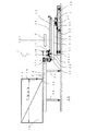
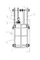
この可動式入庫ステーションにおける長尺荷の受渡し装置については,自動倉庫が設置されている床29上に固定台4が脚20によって設置されており,固定台4に所定の間隔を持って対向して固定ベース5がアンカボルト27にジャッキボルト31を介して床29に設置されている。固定ベース5は,固定台4の高さに合せるように,ジャッキボルト31によって高さ調整ができるように構成されている。固定台4には,長尺荷3の搬入を可能にするようにローラ,ベルトコンベヤ等から成る上流コンベヤ2が設けられている。固定ベース5には,フレーム25を備えたスライドテーブル6が直動ガイド21を介して配設されている。また,直動ガイド21は,固定ベース5に取り付けられた軌道レール30とフレーム25に取り付けられたスライダ32とから構成されている。従って,スライドテーブル6は,固定ベース5に対して直動ガイド21を介して摺動自在に構成されている。また,固定ベース5には,スライドテーブル6を摺動させるための駆動手段を構成する減速機付きモータ10が設けられている。固定ベース5とフレーム25との間には,ピニオン34及びラック35が設けられている。従って,スライドテーブル6は,モータ10を駆動することによって,ピニオン34とラック35を介して固定ベース5上を摺動移動できるように構成されている。実施例ではピニオン・ラックによる動力伝達装置が示されているが,ボールねじ,油圧シリンダ等を用いることができることは勿論である。
With regard to the long load delivery device in this movable warehousing station, the
また,固定台4には,長尺荷3の移動方向の長さLx が任意で不明の場合には,長尺荷3の移動方向の長さを測定するため,測長センサ16が設置されている。長尺荷3の移動方向の長さLx が任意であって,判らない場合には,測長センサ16によって長尺荷3の長さを測定し,その長さ情報をコンピュータに入力し,それによってスライドテーブル6の移動距離を演算して,長尺荷3の移動方向の中心位置を,スタッカクレーンのフォーク9を予め決められた所定の位置の一箇所のフォークの幅方向中心の作動位置へと常に移動させ,そこで,フォーク9を作動してフォーク9で長尺荷3を支持してラックへ入庫する。長尺荷3の移動方向の長さが予め判っている場合には,長尺荷3の長さは既にコンピュータに入力されているので,測長センサ16で長尺荷3の長さを再度測定する必要がないことは勿論である。
Further, when the length Lx in the moving direction of the
図1は,この長尺荷の受渡し装置の基本的概念を説明するための概略図であり,(A)は上流コンベヤ2に対向して設置された固定ベース5上に摺動自在にスライドテーブル6が配設され,スライドテーブル6の上流コンベヤ2側の端部11に設置されたローラ支持台7に長尺荷3を載置できるように近接状態にキャリヤ8が待機している状態を示しており,(B)は最大長さLmax の長尺荷3の両端部12,13をローラ支持台7とキャリヤ8とで支持した状態を示し,(C)は任意の長さLx の長尺荷3の両端部12,13をローラ支持台7とキャリヤ8とで支持した状態を示している。
FIG. 1 is a schematic view for explaining the basic concept of this long load delivery device. FIG. 1A is a slide table slidable on a fixed
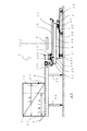
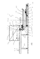
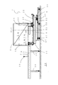
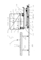
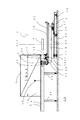
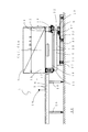
図2〜図5は,この長尺荷の受渡し装置を用いて各種の任意の長さLx を有する長尺荷2を,上流コンベヤ2に位置した工程,長尺荷3の先端側端部12がキャリヤ8に支持された工程,長尺荷3の両端部12,13がキャリヤ8とローラ支持台7に支持された工程を,順次示している説明図である。また,図6〜図8は,この長尺荷の受渡し装置を用いて最大長さLmax を有する長尺荷3が上流コンベヤ2に位置した工程,長尺荷3の先端側端部12がキャリヤ8に支持された工程,及び長尺荷3の両端部12,13がキャリヤ8とローラ支持台7に支持され且つ最大長さLmax の長尺荷3の中心CLw がフォーク9の幅方向中心CLf に位置した工程を,順次示している説明図である。
2 to 5 show a process in which a
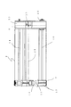
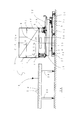
図9には,ローラ支持台7とキャリヤ8が設けられたスライドテーブル6の平面図が示されている。また,図10には,スライドテーブル6の平面図が示されている。スライドテーブル6には,その上面に下部サドル22が配設されており,下部サドル22には,レール18が長尺荷3の移動方向に延びている。また,スライドテーブル6には,固定台4側の端部11にローラ支持台7が固定されており,ローラ支持台7に隣接してレール18上を移動できるキャリヤ8が配設されている。ローラ支持台7には,その上面に長尺荷3をスムーズに走行させるため入庫ローラ17が設けられている。また,キャリヤ8は,その上面が長尺荷3の載置台33に形成されている。キャリヤ8には,レール18上を転動する車輪19,サイドローラ23,及び下ローラ24が設けられている。スライドテーブル6に設けたフレーム25には,キャリヤ8をレール18上を走行させるためのモータ等の駆動手段14が配設されている。従って,キャリヤ8は,モータ等の駆動手段14を駆動することによってチェーン28を介して,レール18上を車輪19,サイドローラ23,及び下ローラ24にガイドされて移動するように構成されている。
FIG. 9 shows a plan view of the slide table 6 on which the
この発明による可動式入庫ステーションにおける長尺荷の受渡し装置は,特に,入庫ステーション1に設置された固定台4上に各種のサイズの移動方向の長さLx を有する長尺荷3を搬入させる上流コンベヤ2,上流コンベヤ2に対向した固定ベース5上に摺動自在に配設されたスライドテーブル6,上流コンベヤ2に対向したスライドテーブル6の端部11に設置されて長尺荷3の後端側端部13を支持するローラ支持台7,長尺荷3の先端側端部12を支持してスライドテーブル6上を移動自在に配設されたキャリヤ8,長尺荷3を自動倉庫におけるラックに搬出入するための長尺荷3を支持するためのスタッカクレーン(図示せず)のフォーク9,及びローラ支持台7とキャリヤ8とによって支持された長尺荷3の移動方向中心CLw をフォーク9が作動する予め決められた所定の位置のフォーク9の幅方向中心CLf に設定するためスライドテーブル6を固定ベース5上で移動させる駆動手段であるモータ10,固定ベース5上でのスライドテーブル6の位置を検出するエンコーダ等から成る検知センサ37から構成されていることを特徴としている。
The delivery device for a long load in a movable storage station according to the present invention is particularly suitable for an upstream in which a
また,この長尺荷の受渡し装置は,上記のように,長尺荷3の任意の長さLx を計測するため上流コンベヤ2に設けられた測長センサ16,キャリヤ8をスライドテーブル6上で移動させるためのモータ等の駆動手段14,スライドテーブル6上でのキャリヤ8の位置を検出するエンコーダ等から成る検知センサ36,及び長尺荷3がスライドテーブル6上でローラ支持台7とキャリヤ8とで長尺荷3の両端部12,13がそれぞれ支持された状態になったことを検知する検知センサ15を備えている。また,この長尺荷の受渡し装置では,フォーク9が作動する所定の位置は,スライドテーブル6に搬入される長尺荷3の最大長さLmax の中心に設定されているものであり,長尺荷3の最小長さLmin (図2〜図5に二点鎖線で概略表示)は,長尺荷3の後端側端部13を支持するローラ支持台7の長さ,長尺荷3の先端側端部12を支持するキャリヤ8の長さ,及びフォーク9の幅の長さの少なくとも総和である。即ち,ローラ支持台7とキャリヤ8との間に,所定の幅を持つフォーク9が配設されて長尺荷3を支持できるように構成されているものである。更に.スライドテーブル6の最大移動長さは,長尺荷3の最大長さLmax からキャリヤ8のスライドテーブル6上の待機位置とローラ支持台7との間の距離を減じた長さに設定されているものである。
In addition, as described above, the long load delivery device includes a
次に,この発明による可動式入庫ステーションにおける長尺荷の受渡し方法の一実施例を説明する。この可動式入庫ステーションにおける長尺荷の受渡し方法は,概して,入庫ステーション1に入庫してくる各種のサイズの長さ即ち任意の長さLx の長尺荷3を,固定ベース5に摺動可能に設置されたスライドテーブル6上に移動可能なキャリヤ8と,スライドテーブル6の上流コンベヤ2側の端部に固定されたローラ支持台7とで支持し,スライドテーブル6を固定ベース5上で移動させ,長尺荷3の移動方向の中心CLw をスタッカクレーン(図示せず)のフォーク9の幅方向の中心CLf に位置合せし,長尺荷3をフォーク9で安定して確実に支持し,その長尺荷3をフォーク9で自動倉庫のラックに収納するものである。
Next, an embodiment of a method for delivering a long load at the movable warehousing station according to the present invention will be described. In general, the method of delivering a long load in the movable warehousing station can slide a
この可動式入庫ステーションにおける長尺荷の受渡し方法は,主として,上流コンベヤ2によって各種のサイズ即ち任意の長さLx の長尺荷3を,固定ベース5上で移動自在なスライドテーブル6の一端部11に設置されたローラ支持台7上に送り込んで長尺荷3をローラ支持台7で移動自在に支持する工程,スライドテーブル6上に移動自在に配設され且つローラ支持台7に近接して待機したキャリヤ8で長尺荷3の先端側端部12を支持させる工程,長尺荷3のスライドテーブル6への搬入に従ってキャリヤ8で長尺荷3の先端側端部12を支持した状態で,キャリヤ8を長尺荷3の任意の長さLx から長尺荷3の後端側端部13とキャリヤ8の待機位置との間の距離を減じた長さ分だけ移動させてローラ支持台7で長尺荷3の後端側端部13を支持させた状態にしてキャリヤ8を停止させる工程,長尺荷3の最大長さLmax の半分の長さから任意の長さLx の半分の長さを減じた長さ分だけスライドテーブル6 を固定ベース5上で移動させて,長尺荷3の移動方向の中心CLw を予め決められた所定の位置で上下動して作動するスタッカクレーンのフォーク9の幅方向の中心CLf に合わせる工程,及び長尺荷3をフォーク9で支持して自動倉庫のラックに搬入させる工程,から構成されていることを特徴としている。
The method of delivering a long load in this movable warehousing station is mainly composed of one end of a slide table 6 which can be moved on a fixed
また,上流コンベヤ2には,長尺荷3の任意の長さLx を計測する測長センサ16が設けられている。更に,この可動式入庫ステーションにおける長尺荷の受渡し方法は,長尺荷3の後端側端部13が測長センサ16を通過した後は,キャリヤ8とスライドテーブル6とは同時に移動させることが可能になっている。また,この長尺荷の受渡し方法では,キャリヤ8の停止位置は,このシステムの最大長さの中心になっている。
The
更に,最大長さLmax の長尺荷3が入庫される時は,スライドテーブル6は動かず,台車であるキャリヤ8が最大長さの停止位置まで動くことができる。この時の長尺荷3の移動方向中心CLw 位置がスタッカクレーンの停止位置になっている。反対に,このシステムの最小長さLmin の長尺荷3の入庫時は,ローラ支持台7とキャリヤ8との間にスタッカクレーンのフォーク9が長尺荷3を支持するため入り込むスペースが形成されるように,キャリヤ8がスライドテーブル6上を移動して停止する。そして,スタッカクレーンの停止位置,長尺荷3の最大長さLmax の中心まで,スライドテーブル6が動くことができる。
Further, when the
この可動式入庫ステーションにおける長尺荷の受渡し方法及びその装置は,上記のように,移動方向の長さが判っていない任意の長尺荷が入庫される場合に,上流コンベヤ2に設けた測長センサ16で長尺荷3の移動方向の長さLx を検出し,検出された長尺荷3の長さLx から,キャリヤ8とスライドテーブル6が動き,スタッカクレーンの停止位置と長尺荷3の移動方向中心CLw を合せるものである。まず,台車のキャリヤ8はスタッカクレーンのフォーク9が入るスペースまで動き,ここが最小長さLmin の長尺荷3のキャリヤ8の停止位置になっている。次いで,検出された長尺荷3の長さLx から最小長さLmin を引いた長さ,その長さ分だけ検知センサ36でスライドテーブル6上でのキャリヤ8の位置を検出して,キャリヤ8が動き,キャリヤ8が停止する。そして,最大長さLmax の半分から,検出された長尺荷3の長さLx の半分を引いた長さ,その長さ分,検知センサ37で固定ベース5上でのスライドテーブル6の位置を検出してスライドテーブル6が動き,スタッカクレーンの停止位置と任意の長さLx の長尺荷3の移動方向中心CLw位置が一致する。このようにして,何種類のサイズに長さの長尺荷3を自動倉庫のラックにスタッカクレーンのフォーク9を使用して入庫することができる。
As described above, the method and apparatus for delivering a long load at this movable warehousing station is provided with the measurement provided in the
この可動式入庫ステーションにおける長尺荷の受渡し方法及びその装置は,スタッカクレーンのフォークを作動して長尺荷を,自動倉庫におけるラックに収容する搬送作業に適用して好ましいものである。 The method and apparatus for delivering a long load at the movable warehousing station is preferably applied to a transporting operation in which a long load is accommodated in a rack in an automatic warehouse by operating a fork of a stacker crane.
1 入庫ステーション
2 上流コンベヤ
3 長尺荷
4 固定台
5 固定ベース
6 スライドテーブル
7 ローラ支持台
8 キャリヤ
9 フォーク
10 減速機付きモータ
11 端部
12 先端側端部
13 後端側端部
14 駆動手段
16 測長センサ
36,37 検知センサ
CLw 長尺荷の移動方向中心
CLf フォークの幅方向中心
Lx 長尺荷の任意長さ
Lmax 長尺荷の最大長さ
Lmin 長尺荷の最小長さ
DESCRIPTION OF
Claims (8)
Priority Applications (1)
| Application Number | Priority Date | Filing Date | Title |
|---|---|---|---|
| JP2010148637A JP5666840B2 (en) | 2010-06-30 | 2010-06-30 | Method and apparatus for delivering a long load at a movable warehousing station |
Applications Claiming Priority (1)
| Application Number | Priority Date | Filing Date | Title |
|---|---|---|---|
| JP2010148637A JP5666840B2 (en) | 2010-06-30 | 2010-06-30 | Method and apparatus for delivering a long load at a movable warehousing station |
Publications (2)
| Publication Number | Publication Date |
|---|---|
| JP2012012144A true JP2012012144A (en) | 2012-01-19 |
| JP5666840B2 JP5666840B2 (en) | 2015-02-12 |
Family
ID=45599047
Family Applications (1)
| Application Number | Title | Priority Date | Filing Date |
|---|---|---|---|
| JP2010148637A Active JP5666840B2 (en) | 2010-06-30 | 2010-06-30 | Method and apparatus for delivering a long load at a movable warehousing station |
Country Status (1)
| Country | Link |
|---|---|
| JP (1) | JP5666840B2 (en) |
Citations (5)
| Publication number | Priority date | Publication date | Assignee | Title |
|---|---|---|---|---|
| JPS49127982U (en) * | 1973-03-01 | 1974-11-01 | ||
| JPS505380U (en) * | 1973-05-15 | 1975-01-21 | ||
| JPS5216777A (en) * | 1975-07-30 | 1977-02-08 | Hitachi Ltd | Transfer apparatus |
| JPH0891507A (en) * | 1994-09-29 | 1996-04-09 | Daifuku Co Ltd | Cargo processing device for automatic warehouse |
| JP2003267513A (en) * | 2002-03-14 | 2003-09-25 | Nippon Yusoki Co Ltd | Positioning device for automatic warehouse |
-
2010
- 2010-06-30 JP JP2010148637A patent/JP5666840B2/en active Active
Patent Citations (5)
| Publication number | Priority date | Publication date | Assignee | Title |
|---|---|---|---|---|
| JPS49127982U (en) * | 1973-03-01 | 1974-11-01 | ||
| JPS505380U (en) * | 1973-05-15 | 1975-01-21 | ||
| JPS5216777A (en) * | 1975-07-30 | 1977-02-08 | Hitachi Ltd | Transfer apparatus |
| JPH0891507A (en) * | 1994-09-29 | 1996-04-09 | Daifuku Co Ltd | Cargo processing device for automatic warehouse |
| JP2003267513A (en) * | 2002-03-14 | 2003-09-25 | Nippon Yusoki Co Ltd | Positioning device for automatic warehouse |
Also Published As
| Publication number | Publication date |
|---|---|
| JP5666840B2 (en) | 2015-02-12 |
Similar Documents
| Publication | Publication Date | Title |
|---|---|---|
| JP4666213B2 (en) | Goods storage equipment | |
| CN105151613B (en) | A kind of automatic vertical library of lifting stack type | |
| KR20120108962A (en) | Article transfer device and stacker crane with same | |
| KR101421265B1 (en) | Transfer equipment and transfer method | |
| JP5783366B2 (en) | Sorting system | |
| KR20100112855A (en) | Automatically vertical loading apparatus | |
| CN102057118B (en) | Parking facility for motor vehicles | |
| JP3864803B2 (en) | Containment equipment | |
| CN106029533A (en) | Device and method for transferring load units | |
| JP4203824B2 (en) | Article conveying device | |
| JP5666840B2 (en) | Method and apparatus for delivering a long load at a movable warehousing station | |
| CN107777624B (en) | Material taking device suitable for industrial vehicle | |
| JPH1135112A (en) | Putting-on-shelf device, putting-on-shelf method to house carrying material in shelf and method of setting receiving conveyor to receiving height in putting-on-shelf device | |
| KR20110003116A (en) | Automatic vertical loading device | |
| JP5105180B2 (en) | Goods storage equipment | |
| JP4826900B2 (en) | Equipment for cargo handling work | |
| JP3927933B2 (en) | Conveyor centering device | |
| JP3002935B2 (en) | Stowage equipment | |
| JP2001019117A (en) | Carrying device | |
| JPH1087079A (en) | Transshipping device | |
| JP4203825B2 (en) | Article conveying device | |
| JPH06144578A (en) | Pallet feeding device | |
| JPH09315519A (en) | Article storing facility | |
| JP2000302207A (en) | Device for putting object on shelf, method for accommodating object to be conveyed in shelf, method for setting receiving conveyor to receiving height in device for putting object on shelf | |
| JP2001301984A (en) | Loading system |
Legal Events
| Date | Code | Title | Description |
|---|---|---|---|
| A621 | Written request for application examination |
Free format text: JAPANESE INTERMEDIATE CODE: A621 Effective date: 20121226 |
|
| A977 | Report on retrieval |
Free format text: JAPANESE INTERMEDIATE CODE: A971007 Effective date: 20131206 |
|
| A131 | Notification of reasons for refusal |
Free format text: JAPANESE INTERMEDIATE CODE: A131 Effective date: 20140114 |
|
| A521 | Request for written amendment filed |
Free format text: JAPANESE INTERMEDIATE CODE: A523 Effective date: 20140313 |
|
| A131 | Notification of reasons for refusal |
Free format text: JAPANESE INTERMEDIATE CODE: A131 Effective date: 20140902 |
|
| A521 | Request for written amendment filed |
Free format text: JAPANESE INTERMEDIATE CODE: A523 Effective date: 20141022 |
|
| TRDD | Decision of grant or rejection written | ||
| A01 | Written decision to grant a patent or to grant a registration (utility model) |
Free format text: JAPANESE INTERMEDIATE CODE: A01 Effective date: 20141202 |
|
| A61 | First payment of annual fees (during grant procedure) |
Free format text: JAPANESE INTERMEDIATE CODE: A61 Effective date: 20141211 |
|
| R150 | Certificate of patent or registration of utility model |
Ref document number: 5666840 Country of ref document: JP Free format text: JAPANESE INTERMEDIATE CODE: R150 |
|
| R250 | Receipt of annual fees |
Free format text: JAPANESE INTERMEDIATE CODE: R250 |
|
| R250 | Receipt of annual fees |
Free format text: JAPANESE INTERMEDIATE CODE: R250 |
|
| R250 | Receipt of annual fees |
Free format text: JAPANESE INTERMEDIATE CODE: R250 |
|
| R250 | Receipt of annual fees |
Free format text: JAPANESE INTERMEDIATE CODE: R250 |