JP2011524776A - Esophageal valve - Google Patents
Esophageal valve Download PDFInfo
- Publication number
- JP2011524776A JP2011524776A JP2011514191A JP2011514191A JP2011524776A JP 2011524776 A JP2011524776 A JP 2011524776A JP 2011514191 A JP2011514191 A JP 2011514191A JP 2011514191 A JP2011514191 A JP 2011514191A JP 2011524776 A JP2011524776 A JP 2011524776A
- Authority
- JP
- Japan
- Prior art keywords
- valve
- esophageal
- valve according
- support structure
- prosthesis
- Prior art date
- Legal status (The legal status is an assumption and is not a legal conclusion. Google has not performed a legal analysis and makes no representation as to the accuracy of the status listed.)
- Pending
Links
- 0 C*(C)OCc1ccc(CCl)cc1 Chemical compound C*(C)OCc1ccc(CCl)cc1 0.000 description 3
- KFQGGWKZGCDLAP-WTKPLQERSA-N C/C=C\[Si](C)(C)OCc1ccc(CCl)cc1 Chemical compound C/C=C\[Si](C)(C)OCc1ccc(CCl)cc1 KFQGGWKZGCDLAP-WTKPLQERSA-N 0.000 description 1
- ZZHIDJWUJRKHGX-UHFFFAOYSA-N ClCc1ccc(CCl)cc1 Chemical compound ClCc1ccc(CCl)cc1 ZZHIDJWUJRKHGX-UHFFFAOYSA-N 0.000 description 1
Images


Classifications
-
- A—HUMAN NECESSITIES
- A61—MEDICAL OR VETERINARY SCIENCE; HYGIENE
- A61F—FILTERS IMPLANTABLE INTO BLOOD VESSELS; PROSTHESES; DEVICES PROVIDING PATENCY TO, OR PREVENTING COLLAPSING OF, TUBULAR STRUCTURES OF THE BODY, e.g. STENTS; ORTHOPAEDIC, NURSING OR CONTRACEPTIVE DEVICES; FOMENTATION; TREATMENT OR PROTECTION OF EYES OR EARS; BANDAGES, DRESSINGS OR ABSORBENT PADS; FIRST-AID KITS
- A61F2/00—Filters implantable into blood vessels; Prostheses, i.e. artificial substitutes or replacements for parts of the body; Appliances for connecting them with the body; Devices providing patency to, or preventing collapsing of, tubular structures of the body, e.g. stents
- A61F2/02—Prostheses implantable into the body
- A61F2/04—Hollow or tubular parts of organs, e.g. bladders, tracheae, bronchi or bile ducts
-
- A—HUMAN NECESSITIES
- A61—MEDICAL OR VETERINARY SCIENCE; HYGIENE
- A61F—FILTERS IMPLANTABLE INTO BLOOD VESSELS; PROSTHESES; DEVICES PROVIDING PATENCY TO, OR PREVENTING COLLAPSING OF, TUBULAR STRUCTURES OF THE BODY, e.g. STENTS; ORTHOPAEDIC, NURSING OR CONTRACEPTIVE DEVICES; FOMENTATION; TREATMENT OR PROTECTION OF EYES OR EARS; BANDAGES, DRESSINGS OR ABSORBENT PADS; FIRST-AID KITS
- A61F2/00—Filters implantable into blood vessels; Prostheses, i.e. artificial substitutes or replacements for parts of the body; Appliances for connecting them with the body; Devices providing patency to, or preventing collapsing of, tubular structures of the body, e.g. stents
- A61F2/02—Prostheses implantable into the body
- A61F2/24—Heart valves ; Vascular valves, e.g. venous valves; Heart implants, e.g. passive devices for improving the function of the native valve or the heart muscle; Transmyocardial revascularisation [TMR] devices; Valves implantable in the body
- A61F2/2412—Heart valves ; Vascular valves, e.g. venous valves; Heart implants, e.g. passive devices for improving the function of the native valve or the heart muscle; Transmyocardial revascularisation [TMR] devices; Valves implantable in the body with soft flexible valve members, e.g. tissue valves shaped like natural valves
- A61F2/2418—Scaffolds therefor, e.g. support stents
-
- A—HUMAN NECESSITIES
- A61—MEDICAL OR VETERINARY SCIENCE; HYGIENE
- A61F—FILTERS IMPLANTABLE INTO BLOOD VESSELS; PROSTHESES; DEVICES PROVIDING PATENCY TO, OR PREVENTING COLLAPSING OF, TUBULAR STRUCTURES OF THE BODY, e.g. STENTS; ORTHOPAEDIC, NURSING OR CONTRACEPTIVE DEVICES; FOMENTATION; TREATMENT OR PROTECTION OF EYES OR EARS; BANDAGES, DRESSINGS OR ABSORBENT PADS; FIRST-AID KITS
- A61F2/00—Filters implantable into blood vessels; Prostheses, i.e. artificial substitutes or replacements for parts of the body; Appliances for connecting them with the body; Devices providing patency to, or preventing collapsing of, tubular structures of the body, e.g. stents
- A61F2/82—Devices providing patency to, or preventing collapsing of, tubular structures of the body, e.g. stents
- A61F2/86—Stents in a form characterised by the wire-like elements; Stents in the form characterised by a net-like or mesh-like structure
- A61F2/90—Stents in a form characterised by the wire-like elements; Stents in the form characterised by a net-like or mesh-like structure characterised by a net-like or mesh-like structure
-
- A—HUMAN NECESSITIES
- A61—MEDICAL OR VETERINARY SCIENCE; HYGIENE
- A61F—FILTERS IMPLANTABLE INTO BLOOD VESSELS; PROSTHESES; DEVICES PROVIDING PATENCY TO, OR PREVENTING COLLAPSING OF, TUBULAR STRUCTURES OF THE BODY, e.g. STENTS; ORTHOPAEDIC, NURSING OR CONTRACEPTIVE DEVICES; FOMENTATION; TREATMENT OR PROTECTION OF EYES OR EARS; BANDAGES, DRESSINGS OR ABSORBENT PADS; FIRST-AID KITS
- A61F2/00—Filters implantable into blood vessels; Prostheses, i.e. artificial substitutes or replacements for parts of the body; Appliances for connecting them with the body; Devices providing patency to, or preventing collapsing of, tubular structures of the body, e.g. stents
- A61F2/02—Prostheses implantable into the body
- A61F2/04—Hollow or tubular parts of organs, e.g. bladders, tracheae, bronchi or bile ducts
- A61F2002/044—Oesophagi or esophagi or gullets
-
- A—HUMAN NECESSITIES
- A61—MEDICAL OR VETERINARY SCIENCE; HYGIENE
- A61F—FILTERS IMPLANTABLE INTO BLOOD VESSELS; PROSTHESES; DEVICES PROVIDING PATENCY TO, OR PREVENTING COLLAPSING OF, TUBULAR STRUCTURES OF THE BODY, e.g. STENTS; ORTHOPAEDIC, NURSING OR CONTRACEPTIVE DEVICES; FOMENTATION; TREATMENT OR PROTECTION OF EYES OR EARS; BANDAGES, DRESSINGS OR ABSORBENT PADS; FIRST-AID KITS
- A61F2/00—Filters implantable into blood vessels; Prostheses, i.e. artificial substitutes or replacements for parts of the body; Appliances for connecting them with the body; Devices providing patency to, or preventing collapsing of, tubular structures of the body, e.g. stents
- A61F2/02—Prostheses implantable into the body
- A61F2/04—Hollow or tubular parts of organs, e.g. bladders, tracheae, bronchi or bile ducts
- A61F2002/045—Stomach, intestines
-
- C—CHEMISTRY; METALLURGY
- C08—ORGANIC MACROMOLECULAR COMPOUNDS; THEIR PREPARATION OR CHEMICAL WORKING-UP; COMPOSITIONS BASED THEREON
- C08L—COMPOSITIONS OF MACROMOLECULAR COMPOUNDS
- C08L83/00—Compositions of macromolecular compounds obtained by reactions forming in the main chain of the macromolecule a linkage containing silicon with or without sulfur, nitrogen, oxygen or carbon only; Compositions of derivatives of such polymers
- C08L83/10—Block- or graft-copolymers containing polysiloxane sequences
Abstract
外側支持領域(2)と、少なくとも3つの弁葉状体(3、4、5)と、支持領域(2)と弁葉状体(3、4、5)の間に伸びる本体領域(6)とを有するポリマー弁体を含む食道弁(1)。弁(1)は、弁(1)が閉鎖された常閉構成と、弁葉状体(3、4、5)が順行力に応答して開放されて、弁(1)を通じた流れを可能にする順行開放構成と、順行力より実質的に大きい逆行力に応答する逆行開放構成とを有する。 An outer support region (2), at least three leaflets (3, 4, 5), and a body region (6) extending between the support region (2) and the leaflets (3, 4, 5). An esophageal valve (1) comprising a polymer valve body. The valve (1) has a normally closed configuration in which the valve (1) is closed, and the leaflets (3, 4, 5) are opened in response to an antegrade force to allow flow through the valve (1). And a reverse release configuration that responds to a reverse force substantially greater than the forward force.
Description
食道ステントは、良性の狭窄または悪性の閉塞を治療するために下部食道括約筋(LES)にしばしば配置される。しかし、結果として生じる逆流遮断壁の損失は、相当量の酸逆流をもたらすことが多く、これは既に病気の患者の生活の質を低下させるおそれがある。 Esophageal stents are often placed in the lower esophageal sphincter (LES) to treat benign strictures or malignant obstructions. However, the resulting loss of reflux barrier often results in a significant amount of acid reflux, which can reduce the quality of life for an already sick patient.
胃噴門に配置されるこのような食道ステントは、ステントの下から胃にぶら下がる軟質のスリーブを備えることもある。これらの所謂「ウィンドソック(吹き流し、風見用円錐筒)」状装置は、スリーブを平坦化および閉鎖する胃のわずかな圧力の上昇に依存する。 Such esophageal stents placed in the gastric cardia may include a soft sleeve that hangs from below the stent to the stomach. These so-called “windsock” devices rely on a slight increase in stomach pressure that flattens and closes the sleeve.
しかし、既存のインステント逆流技術にはいくつかの問題がある。患者がげっぷまたは嘔吐したいときに、これらの装置の多くは、完全に封鎖して、逆流を防止し、患者に著しい不快感を与える。場合によっては、スリーブが逆転して逆行の流れを可能にすることができるが、次いで逆の状態を維持し、食道の封鎖を引き起こし得る。加えて、このようなスリーブは、一般に、蠕動が有効でないステントの遠端に存在するため、食物が装置のこの部分に突き刺さる危険性がある。別の問題は、これらの弁を構成する材料が、胃の環境内でしばしば劣化して、装置の効果を経時的に低下させる。 However, there are several problems with existing in-stent reflux technology. When a patient wants to burp or vomit, many of these devices are completely sealed to prevent backflow and cause significant discomfort to the patient. In some cases, the sleeve can be reversed to allow retrograde flow, but can then maintain the reverse and cause esophageal blockage. In addition, such sleeves are generally present at the distal end of the stent where peristalsis is not effective, so there is a risk of food sticking into this part of the device. Another problem is that the materials that make up these valves often degrade within the stomach environment, reducing the effectiveness of the device over time.
本発明によれば、
弁が閉鎖された常閉構成と、
弁葉状体が順行力に応答して開放されて、弁を通じた流れを可能にする順行開放構成と、
順行力より実質的に大きい逆行力に応答する逆行開放構成と
を有する食道弁が提供される。
According to the present invention,
A normally closed configuration with the valve closed;
An antegrade opening configuration in which the leaflets are opened in response to an antegrade force to allow flow through the valve;
An esophageal valve is provided having a retrograde open configuration that is responsive to a retrograde force that is substantially greater than an antegrade force.
一実施形態において、弁は、外側支持枠と、少なくとも3つの弁葉状体と、支持枠と弁葉状体の間に伸びる本体領域とを有するポリマー弁体を含む。
本発明は、また、少なくとも4つの弁葉状体を含む、体管腔に配置するための管腔弁であって、弁葉状体が係合された常閉構成と、弁葉状体が開放された開放構成とを有する管腔弁を提供した。少なくとも5つの弁葉状体が存在してよい。6つの弁葉状体が存在してよい。
In one embodiment, the valve includes a polymer valve body having an outer support frame, at least three leaflets, and a body region extending between the support frame and the leaflets.
The present invention also includes a lumen valve for placement in a body lumen, including at least four leaflets, wherein the valve leaflets are open and a normally closed configuration with the leaflets engaged. A luminal valve having an open configuration is provided. There may be at least five leaflets. There may be six leaflets.
1つの実例において、弁は食道弁である。1つの実例において、弁は、弁葉状体が順行力に応答して開放されて、弁を通じた流れを可能にする順行開放構成と、順行力より実質的に大きい逆行力に応答する逆行開放構成とを有する。 In one example, the valve is an esophageal valve. In one example, the valve is responsive to a retrograde force that is substantially greater than the antegrade force and a antegrade opening configuration in which the leaflets are opened in response to the antegrade force to allow flow through the valve. With a retrograde open configuration.
弁は、ポリマー材料の弁体を有することができる。弁は、外側支持領域を有することができる。弁は、支持領域と弁葉状体の間に伸びる本体領域を有することもできる。
1つの実例において、本体領域は、一般には、外側支持枠と弁葉状体の接合領域との間が凹形である。
The valve can have a valve body of polymeric material. The valve can have an outer support region. The valve can also have a body region that extends between the support region and the leaflet.
In one example, the body region is generally concave between the outer support frame and the junction region of the leaflets.
一実施形態において、弁葉状体および本体領域の少なくとも一部が逆転して、逆行方向の流れを可能にする。好ましくは、逆行力が低下すると、主弁領域および弁葉状体が裏返って常閉構成になる。 In one embodiment, at least a portion of the leaflets and body region are reversed to allow retrograde flow. Preferably, when the retrograde force decreases, the main valve region and the leaflets turn over to form a normally closed configuration.
1つの実例において、弁葉状体は接合領域を有し、弁体は接合領域が強化されている。弁体は、接合領域が厚くなっていてよい。
接合領域は、少なくとも1mmの軸方向長さにわたって伸びていてよい。接合領域は、1mmから5mmの深さにわたって伸びていてよい。
In one example, the leaflet has a joint region, and the valve body has a strengthened joint region. The valve body may have a thick junction area.
The joining area may extend over an axial length of at least 1 mm. The joining area may extend over a depth of 1 mm to 5 mm.
一実施形態において、弁体の支持枠は強化されている。弁の支持枠は厚くなっていてよい。
一実施形態において、弁は3つの弁葉状体を含む。
In one embodiment, the support frame of the valve body is reinforced. The valve support frame may be thick.
In one embodiment, the valve includes three leaflets.
別の実施形態において、弁は6つの弁葉状体を含む。
本発明はまた、弁の支持構造体を含む食道弁を提供する。
弁は、支持構造体に装着されていてよい。
In another embodiment, the valve includes six leaflets.
The present invention also provides an esophageal valve that includes a support structure for the valve.
The valve may be attached to the support structure.
1つの実例において、弁枠は、支持構造体に縫合されている。代替的または追加的に、弁枠は、支持構造体に接合されている。
一実施形態において、支持構造体は、管腔補綴体を含む。
In one example, the valve frame is stitched to the support structure. Alternatively or additionally, the valve frame is joined to the support structure.
In one embodiment, the support structure includes a luminal prosthesis.
1つの実例において、管腔補綴体は、弁の近位方向に伸びる。
別の実例において、管腔補綴体は、弁の遠位方向に伸びる。
一実施形態において、管腔補綴体は、弁の近位および遠位方向に伸びる。
In one example, the luminal prosthesis extends proximally of the valve.
In another example, the luminal prosthesis extends in the distal direction of the valve.
In one embodiment, the luminal prosthesis extends in the proximal and distal directions of the valve.
管腔補綴体は、コーティングおよび/またはスリーブをその上に有することができる。コーティングまたはスリーブは、管腔補綴体の外側に存在し得る。あるいは、コーティングまたはスリーブは、管腔補綴体の内側に存在する。 The luminal prosthesis can have a coating and / or a sleeve thereon. The coating or sleeve can be on the outside of the luminal prosthesis. Alternatively, the coating or sleeve is present inside the luminal prosthesis.
一実施形態において、順行方向の0.7mmHgの圧力は、140ml/分の流速を可能にするのに十分である。
一実施形態において、弁を開放するのに必要な逆行力は、15mmHgより大きく、40mmHgより小さい圧力である。
In one embodiment, a 0.7 mm Hg pressure in the forward direction is sufficient to allow a flow rate of 140 ml / min.
In one embodiment, the retrograde force required to open the valve is a pressure greater than 15 mmHg and less than 40 mmHg.
一実施形態において、ポリマー材料は、胃液に対して、少なくとも3ヶ月間、少なくとも4ヶ月間、少なくとも5ヶ月間、少なくとも6ヶ月間、少なくとも7ヶ月間、少なくとも8ヶ月間、少なくとも9ヶ月間、少なくとも10ヶ月間、少なくとも11ヶ月間または少なくとも1年間にわたって安定である。 In one embodiment, the polymeric material is at least 3 months, at least 4 months, at least 5 months, at least 6 months, at least 7 months, at least 8 months, at least 9 months, at least for gastric juice Stable for 10 months, at least 11 months or at least 1 year.
1つの実例において、ポリマー材料は、平衡状態で、約5重量%未満、約10重量%未満、約15重量%未満、約20重量%未満、約25重量%未満または約30重量%未満の水を吸収する。 In one example, the polymeric material has, in equilibrium, less than about 5 wt%, less than about 10 wt%, less than about 15 wt%, less than about 20 wt%, less than about 25 wt%, or less than about 30 wt% water. Absorbs.
1つの実例において、弁体のポリマー材料は、50%から3000%または200%から1200%の伸度(%)を有する。
1つの実例において、弁体のポリマー材料は、0.01から5MPa、または約0.1から1.0MPa、または約0.25から0.5MPaの引張強度を有する。
In one example, the valve body polymer material has an elongation (%) of 50% to 3000% or 200% to 1200%.
In one example, the polymeric material of the valve body has a tensile strength of 0.01 to 5 MPa, or about 0.1 to 1.0 MPa, or about 0.25 to 0.5 MPa.
一実施形態において、ポリマー材料は、約0.01から0.6MPa、または約0.1から約0.5MPaのヤング率を有する。
一実施形態において、弁体のポリマー材料は、0.1g/cm3から1.5g/cm3、または0.3から1.2g/cm3、または0.8から0.9g/cm3、または0.5から0.6g/cm3の密度を有する。
In one embodiment, the polymeric material has a Young's modulus of about 0.01 to 0.6 MPa, or about 0.1 to about 0.5 MPa.
In one embodiment, the polymeric material of the valve body is 0.1 g / cm 3 to 1.5 g / cm 3 , or 0.3 to 1.2 g / cm 3 , or 0.8 to 0.9 g / cm 3 , Or a density of 0.5 to 0.6 g / cm 3 .
一実施形態において、弁体の支持領域の近端と弁葉状体の遠端との距離は、50mm未満、または40mm未満、または30mm未満、または25mm未満、または20mm未満、または15mm未満である。 In one embodiment, the distance between the proximal end of the support region of the valve body and the distal end of the leaflet is less than 50 mm, or less than 40 mm, or less than 30 mm, or less than 25 mm, or less than 20 mm, or less than 15 mm.
1つの実例において、弁体のポリマー材料は、弾性材料である。
別の実例において、弁体のポリマー材料は、粘弾性材料である。
一実施形態において、弁体のポリマー材料は、発泡体を含む。弁体のポリマー材料は、連続気泡発泡体を含むことができる。
In one example, the polymer material of the valve body is an elastic material.
In another example, the polymeric material of the valve body is a viscoelastic material.
In one embodiment, the polymeric material of the valve body comprises a foam. The polymeric material of the valve body can include an open cell foam.
一実施形態において、弁体のポリマー材料は、ポリウレタン発泡体を含む。
一実施形態において、食道弁は、予め展開された支持構造体、例えば、ステントなどの食道管腔補綴体に装着されるように構成される。
In one embodiment, the polymeric material of the valve body comprises a polyurethane foam.
In one embodiment, the esophageal valve is configured to be attached to a pre-deployed support structure, eg, an esophageal lumen prosthesis such as a stent.
本発明はまた、
弁が閉鎖された常閉構成と、
弁を通じた流れを可能にするために弁が開放された開放構成と、
予め展開された管腔補綴体の近端と遠端との中間において、予め展開された管腔補綴体に装着するように構成される、弁の支持体と
を有する弁を提供する。
The present invention also provides
A normally closed configuration with the valve closed;
An open configuration in which the valve is open to allow flow through the valve;
A valve having a valve support configured to attach to a pre-deployed luminal prosthesis intermediate a proximal end and a distal end of the pre-deployed luminal prosthesis is provided.
1つの実例において、弁は、食道ステントに装着する食道弁である。
一実施形態において、弁支持領域は、支持構造体に縫合されている。
弁支持領域は、支持構造体に接合されている。
In one example, the valve is an esophageal valve that attaches to an esophageal stent.
In one embodiment, the valve support region is sewn to the support structure.
The valve support region is joined to the support structure.
管腔補綴体は、弁の近位方向に伸びていてよい。管腔補綴体は、弁の遠位方向に伸びていてよい。管腔補綴体は、弁の近位および遠位方向に伸びていてよい。
1つの実例において、管腔補綴体は、コーティングおよび/またはスリーブをその上に有する。コーティングまたはスリーブは、管腔補綴体の外側に存在し得る。代替的または追加的に、コーティングまたはスリーブは、管腔補綴体の内側に存在する。
The luminal prosthesis may extend proximally of the valve. The luminal prosthesis may extend distally of the valve. The luminal prosthesis may extend in the proximal and distal directions of the valve.
In one example, the luminal prosthesis has a coating and / or sleeve thereon. The coating or sleeve can be on the outside of the luminal prosthesis. Alternatively or additionally, the coating or sleeve is present inside the luminal prosthesis.
一実施形態において、弁は、食道ステントなどの予め展開された食道管腔補綴体に装着されるように構成される。
弁を予め展開された食道管腔補綴体に装着する装着手段が存在し得る。装着手段は、弁に設けられていてよい。
In one embodiment, the valve is configured to be attached to a pre-deployed esophageal lumen prosthesis, such as an esophageal stent.
There may be attachment means for attaching the valve to the pre-deployed esophageal lumen prosthesis. The mounting means may be provided on the valve.
1つの実例において、装着手段は、予め展開されたステントとの係合のための係合手段を含む。
弁は、支持構造体を含むことができる。支持構造体は、外側または内側に向かって先細りしてよい。
In one example, the attachment means includes engagement means for engagement with a pre-deployed stent.
The valve can include a support structure. The support structure may taper outward or inward.
1つの実例において、支持構造体は、一般に、その長さに沿って均一な直径を有する。
一実施形態において、支持構造体は骨格を含む。支持構造体は、ステント様構造体を含むことができる。
In one example, the support structure generally has a uniform diameter along its length.
In one embodiment, the support structure includes a skeleton. The support structure can include a stent-like structure.
装着手段は、支持構造体によって設けられていてよい。1つの実例において、装着手段は、支持構造体から伸びる突起を含む。突起は、予め展開されたホスト食道管腔補綴体と係合するように構成されてよい。 The mounting means may be provided by a support structure. In one example, the mounting means includes a protrusion extending from the support structure. The protrusion may be configured to engage a pre-deployed host esophageal lumen prosthesis.
一実施形態において、突起はループを含む。
1つの実例において、突起の先端が丸められている。
突起は、予め展開されたホスト食道管腔補綴体と解放可能に係合可能であってよい。
In one embodiment, the protrusion includes a loop.
In one example, the tip of the protrusion is rounded.
The protrusion may be releasably engageable with a pre-deployed host esophageal lumen prosthesis.
予め展開されたホスト食道管腔補綴体との係合から弁を解放する解放手段が存在してよい。解放手段は、弁支持構造体の少なくとも一部の直径を小さくする手段を含むことができる。 There may be a release means for releasing the valve from engagement with the pre-deployed host esophageal lumen prosthesis. The release means can include means for reducing the diameter of at least a portion of the valve support structure.
1つの実例において、解放手段は、弁支持構造体付近に伸びる引張糸集合体を含む。第1の引張糸集合体は、支持体の近端付近に伸びていてよい。第2の引張糸集合体は、支持構造体の遠端付近に伸びていてよい。 In one example, the release means includes an assembly of tension yarns extending near the valve support structure. The first tensile yarn assembly may extend near the proximal end of the support. The second tensile yarn assembly may extend near the far end of the support structure.
一実施形態において、弁は支持構造体に装着されている。弁は支持構造体に縫合されていてよい。弁は支持構造体に接合されていてよい。弁は支持構造体に接着接合されていてよい。 In one embodiment, the valve is attached to the support structure. The valve may be sutured to the support structure. The valve may be joined to the support structure. The valve may be adhesively bonded to the support structure.
別の実例において、装着手段は、外科用接着剤を含む。
本発明はまた、体管路に弁を設けるための方法であって、
支持構造体に装着された弁を設けるステップと、
支持構造体に装着された弁を、体管路における予め展開された管腔補綴体に送達するステップと、
弁が管腔補綴体に装着されるように弁を配置するステップと
を含む方法を提供する。
In another example, the attachment means includes a surgical adhesive.
The present invention is also a method for providing a valve in a body conduit,
Providing a valve attached to the support structure;
Delivering a valve attached to the support structure to a pre-deployed luminal prosthesis in a body duct;
Positioning the valve such that the valve is attached to the luminal prosthesis.
一実施形態において、弁を配置するステップは、弁支持体を予め展開された管腔補綴体と係合させるステップを含む。
弁支持体を予め展開された管腔補綴体と機械的に係合させることができる。
In one embodiment, positioning the valve includes engaging the valve support with a pre-deployed luminal prosthesis.
The valve support can be mechanically engaged with a pre-deployed luminal prosthesis.
1つの実例において、弁支持体は突起を含み、該方法は、突起と管腔内補綴体の開口との位置を合わせ、突起を開口に係合させるステップを含む。
一実施形態において、弁支持体は、膨張性支持体であり、該方法は、支持体を収縮させた形で送達カテーテルに装填するステップを含み、支持体は、配置されると膨張可能である。
In one example, the valve support includes a protrusion, and the method includes aligning the protrusion with the opening of the endoluminal prosthesis and engaging the protrusion with the opening.
In one embodiment, the valve support is an expandable support and the method includes loading the support into a delivery catheter in a contracted form, the support being inflatable when deployed. .
支持体は、自己膨張性であり、支持体は、バルーンなどの膨張手段によって膨張される。
一実施形態において、該方法は、弁支持体を管腔補綴体との係合から解放するステップを含む。
The support is self-expanding and the support is inflated by inflating means such as a balloon.
In one embodiment, the method includes releasing the valve support from engagement with the luminal prosthesis.
該方法は、弁支持体を補綴体内に再配置するステップを含むことができる。該方法は、弁を補綴体から除去するステップを含む。
一実施形態において、体管路は食道であり、弁は、予め展開された食道ステントに装着するための食道弁である。
The method can include repositioning the valve support within the prosthesis. The method includes removing the valve from the prosthesis.
In one embodiment, the body tract is the esophagus and the valve is an esophageal valve for attachment to a pre-deployed esophageal stent.
1つの実例において、弁の支持構造体が存在する。弁を支持構造体に装着することができる。弁支持領域を支持構造体に縫合することができる。代替的または追加的に、弁支持領域は、支持構造体に接合される。1つの実例において、支持構造体は、弁支持領域にオーバーモールドされる。 In one example, there is a valve support structure. The valve can be attached to the support structure. The valve support region can be sewn to the support structure. Alternatively or additionally, the valve support area is joined to the support structure. In one example, the support structure is overmolded to the valve support region.
支持構造体は、管腔補綴体を含むことができる。
一実施形態において、管腔補綴体は、弁の近位方向に伸びる。補綴体は、自己膨張プラスチック網目を含むことができる。補綴体は、1.9kPa未満の半径方向力を加えることができる。
The support structure can include a luminal prosthesis.
In one embodiment, the luminal prosthesis extends proximally of the valve. The prosthesis can include a self-expanding plastic network. The prosthesis can apply a radial force of less than 1.9 kPa.
一実施形態において、補綴体を原位置で装着するためのアンカーが存在する。アンカーは、補綴体の網目を伸びるように構成されてよい。
1つの実例において、補綴体は、噴門に固定されるように構成される。
In one embodiment, there is an anchor for mounting the prosthesis in situ. The anchor may be configured to extend the mesh of the prosthesis.
In one example, the prosthesis is configured to be secured to the cardia.
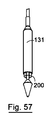
一実施形態において、支持領域の近端から弁葉状体の遠端までの弁の長さは、50mm未満、40mm未満、30mm未満である。弁の長さは、弁の支持領域の外径とほぼ同じであってよい。弁の長さは、約23mmであってよい。 In one embodiment, the length of the valve from the proximal end of the support region to the distal end of the leaflet is less than 50 mm, less than 40 mm, less than 30 mm. The length of the valve may be approximately the same as the outer diameter of the support area of the valve. The length of the valve may be about 23 mm.
別の態様において、本発明は、逆流性食道炎を治療するための方法であって、本発明の弁を設け、弁を所望の場所に配置するステップを含む方法を含む。所望の場所は、下部食道括約筋の全域であってよい。1つの実例において、弁葉状体は、食道の端部から遠くに配置される。一実施形態において、弁に支持構造体が設けられ、該方法は、支持構造体を所望の場所に装着するステップを含む。該方法は、支持構造体を体壁の所望の場所に固定するステップを含むことができる。1つの実例において、該方法は、支持構造体を噴門に固定するステップを含む。 In another aspect, the present invention includes a method for treating reflux esophagitis comprising providing a valve of the present invention and placing the valve in a desired location. The desired location may be the entire area of the lower esophageal sphincter. In one example, the leaflets are placed far from the end of the esophagus. In one embodiment, the valve is provided with a support structure, and the method includes mounting the support structure at a desired location. The method can include securing the support structure to a desired location on the body wall. In one example, the method includes securing the support structure to the cardia.
本発明は、例示のみを目的として示されるその以下の説明からより明確に理解されるであろう。 The present invention will be understood more clearly from the following description, given by way of example only.
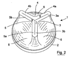
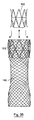
図面として最初に図1から22を参照すると、順行方向(食物摂取方向)および逆行方向(胃から口への方向)で自動的に開放することができる食道弁1が示されている。
弁1は、枠2を有する近位外側支持領域と、少なくとも3つの弁葉状体(弁リーフレット、弁尖頭部)3、4、5と、支持枠2と弁葉状体3、4、5の間に伸びる本体領域6とを有するポリマー弁体を含む。弁葉状体3、4、5は、内方向および遠方に伸び、それぞれ遠端面7、8、9で終端する。弁葉状体3、4、5は、それぞれ、互いに120°の先端角で伸びる脚a、bを有する。脚3a;4a:4b;5b;5a;3b;の隣接対は、弁が常閉構成であるときに弁葉状体の間の空隙を閉鎖するように接合する。
Referring first to FIGS. 1-22 as a drawing, there is shown an
The
弁1は3つの構成を有する。第1の構成は、弁葉状体3、4、5が弁を閉鎖するように接合する常閉構成である。第2の構成は、弁葉状体脚対3a;4a;4b;5b;5a;3bが順行力F1に応答して開放および離間されて、弁を通じた流れを可能にするように、弁葉状体3、4、5が開放される順行開放構成である。第3の構成は、順行力より実質的に大きい逆行力F2に応答する逆行開放構成である。
The
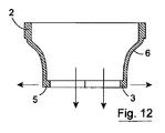
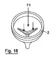
弁1の様々な構成が図11から22に示されている。第1のまたは常閉構成(図11、17)において、弁葉状体3、4、5が接合する。順行力F1が弁葉状体3、4、5に加えられると、弁葉状体脚対3a;4a;4b;5b;および5a;3bが開放して順行流の流れを可能にする(図12、19)。図18は、順行流に応答する部分開放構成を示す。順行力F1が除去されると、弁葉状体3、4、5は、弁体のポリマー材料の固有偏倚下で閉鎖位置に戻る(図13)。
Various configurations of the
逆行力F2が弁体に加えられる。この力は、最初に弁葉状体3、4、5を互いに押しつけ、圧力が設定値を超えると、弁体が逆転する。逆転の開始が図21に示される。弁が、逆行力に応答して完全に開放されると、弁本体(および弁葉状体3、4、5)が、図15および22に示されるように近方向に(上方に)伸びる。これは、逆行流のバルブを通じた流れを可能にする。逆行力F2が除去されると、弁本体は、ポリマー材料の偏倚に応答して裏返ることによって本来の構成に戻ることで、図16および20に示されるように弁葉状体が遠方に伸びる常閉構成に戻る。
A retrograde force F2 is applied to the valve body. This force initially pushes the
弁葉状体3、4、5は、接合の領域で強化される。この場合、これは、この領域におけるポリマー材料を局部的に厚くすることによって達成される。同様に、支持枠2は、ポリマー材料を局部的に厚くすることによって強化される。
The
弁葉状体3、4、5の接合領域は、典型的には1から5mmである軸方向の広がりを有する。これは、弁が常閉構成であるときに大きな界面領域にわたる弁葉状体の完全な接合を保証する。接合領域における弁葉状体の厚さは、典型的には、0.1mmから10mmである。
The junction region of the
弁体は、全体的に凹形の外面および全体的に凸形の内面を有する。
弁1は二方弁である。近方向または遠方向から弁を開放するのに異なる力が必要である。弁1は、順行方向で開放するために非常にわずかな力しか必要とせず、140ml/分の流量を可能にするのに順行方向での0.7mmHgの圧力で十分である。逆行方向において、弁1は、15mmHgから40mmHg以上の圧力を保持することができる。弁の材料の特性(密度など)を変えることによって、変化する降伏圧力に対応するように弁を調整することができる。弁は、逆行方向の圧力下に配置されると、制御可能に逆転することによってこれを達成する。
The valve body has a generally concave outer surface and a generally convex inner surface.
The
本発明の弁1は、逆行方向で完全に開放された後に、その本来の使用位置に戻る。これは、使用弁を損なうことなく達成される。
食物が逆行方向に流れることによって弁が開放されると、弁葉状体が開放する。弁の外面は、形状の変化に対してより大きな抵抗を有するため、逆行方向で本体を開放するのに必要な力はより大きくなる。
The
When the valve is opened by the flow of food in the retrograde direction, the leaflets are opened. Since the outer surface of the valve has a greater resistance to shape changes, the force required to open the body in the retrograde direction is greater.
弁の機能に影響を与える重要な特性は、互いに衝突する弁葉状体脚である。弁葉状体3、4、5の幾何学的構造および長さを変えることによって、弁1を異なる圧力で逆行方向に開放させることができる。順行方向の開放は、弁葉状体の幾何学構造への依存が幾分小さく、装置を構成する材料の弾性および密度により大きく依存する。また、全直径、および弁葉状体が開放する直径は、両方向の開放力に影響を与える。
An important characteristic that affects the function of the valve is the leaflets that collide with each other. By changing the geometry and length of the
胃は、食道よりわずかに大きな圧力を有する(平均の差はほぼ12mmHgである)ため、閉じた弁は、その遠端面でこの圧力を受けることになる。この遠端圧力は、遠方に伸びる面または先細りする面の閉鎖を改善することができる。しかし、文献における弁の先の実施例は、胃の圧力差を利用するために平滑面に依存していた。したがって、胃の圧力によって生成される力を最大にする唯一の手段は、遠方に伸びる面または先細りする面の長さを大きくするものであった。これは、次に、細長い構造体が食物の順行流および逆行流で封鎖されることに伴う問題を生じた。本発明は、弁構造体の長さを短く維持し、表面積対長さの比の増加を介して胃の圧力により生成される力を最大にする方法を教示する。これは、プリーツまたはヒダ(弁葉状体)を導入することによって弁の遠端面の表面積を増加させることによって達成される。 Since the stomach has a slightly greater pressure than the esophagus (the average difference is approximately 12 mmHg), a closed valve will experience this pressure at its distal end face. This far end pressure can improve the closure of the far extending or tapering surface. However, previous examples of valves in the literature relied on smooth surfaces to take advantage of gastric pressure differences. Thus, the only means of maximizing the force generated by gastric pressure has been to increase the length of the far-extending or tapered surface. This in turn caused problems with the elongate structures being sequestered in the forward and backward flow of food. The present invention teaches a method of keeping the length of the valve structure short and maximizing the force generated by gastric pressure through an increase in the surface area to length ratio. This is accomplished by increasing the surface area of the far end face of the valve by introducing pleats or pleats.
弁は、任意の好適な生体適合性ポリマー材料で構成されてよい。弁が上記のように機能することを可能にする特性を有する生体適合性ポリマー材料であってよい。
この弁の製造に使用される材料は、50%から3000%の伸度(%)を有する。その材料は、また、0.01から5MPaの引張強度を有する。また、その材料は、インビトロでコロニー形成を防止する抗微生物作用を有することが可能である。また、その材料は、弾性または粘弾性であり、場合によって連続気泡発泡体であり得る。その材料の密度は、0.1g/cm3から1.5g/cm3である。
The valve may be constructed of any suitable biocompatible polymer material. It may be a biocompatible polymeric material having properties that allow the valve to function as described above.
The material used to make this valve has an elongation (%) of 50% to 3000%. The material also has a tensile strength of 0.01 to 5 MPa. The material can also have an antimicrobial action to prevent colony formation in vitro. The material is also elastic or viscoelastic, and may optionally be an open cell foam. The density of the material is from 0.1 g / cm3 to 1.5 g / cm3.
本発明の弁を任意の好適な管腔補綴体、特に食道補綴体またはステントに装着することができる。弁の枠2は、ステント20内に装着するための装着環を提供し、例えば、図24および図25に示される縫合糸21を使用して枠2をステント網目に縫合することによって弁1をステントに装着することができる。
The valve of the present invention can be attached to any suitable luminal prosthesis, particularly an esophageal prosthesis or stent. The
ステントは任意の好適なタイプであってよい。コーティングまたはスリーブが施されていないステント20が、図23から25に示されている。あるいは、組織内植を防止することが望まれる場合は、スリーブ31を有するステント30を使用することができる(図26から29)。この場合、スリーブ31は、ステントの外部である。他の実例において、代替的または追加的に内部スリーブが存在し得る。さらに、ステントは、コーティングを有することができる。
The stent may be of any suitable type. A
上記のような弁を予め展開された管腔補綴体に入れることもできる。例えば、弁は、食道における予め展開されたステントに入れるための食道弁であってよい。
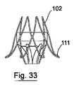
1つの実例において、弁100は、共軸支持構造体を有することができ、または骨格102が図31および31に示されている。骨格102は、図35に示される任意の好適な食道ステント140と係合するように設計される。係合の機構は、既存の予め展開されたステント140の網目に係合する骨格102の近位および/または遠位先端103であってよい突起によるものであり得る。代替的または追加的に、骨格102は、図37および38に示される食道ステントの支柱の内側に掛かるように設計された特徴150を有することができる。
A valve as described above can also be placed in a pre-deployed luminal prosthesis. For example, the valve may be an esophageal valve for placement in a pre-deployed stent in the esophagus.
In one example, the
図32および33を参照すると、骨格の遠位先端111が既存の予め展開されたホストステント140の網目と係合するように、支持構造体または骨格102が遠方外方向に先細りする本発明の別の実施形態による弁110が示されている。
Referring to FIGS. 32 and 33, another embodiment of the present invention in which the support structure or
図34を参照すると、骨格102の近位先端121が既存の予め展開されたステント140の網目と係合するように、支持構造体または骨格102が遠方内方向に先細りする本発明による別の弁120が示されている。
Referring to FIG. 34, another valve according to the present invention in which the support structure or
骨格102の半径方向力は、突起を必要とすることなく弁を所定位置に保持するのに十分な摩擦力を加えることができる。別の実施形態において、外科用接着剤を使用して、レトロフィッテド弁を所定位置に固定することができる。
The radial force of the
図39から43を参照すると、弁100は、展開のために送達システム130に導入される。送達システム130の外径は、予め展開された食道ステント140の内径より小さい。この場合の送達システム130は、弁が収縮構成で収容される、遠位ポッド131を有する送達カテーテルを含む。カテーテルは、予め展開されたステント140のたるみを回避するために先細りした遠位先端132を有する。ポッド131は、ポッド131から弁を解放するために先端132に対して軸方向に移動可能である。
Referring to FIGS. 39-43, the
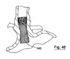
送達システム130は、図44に示される予め展開されたステント140に弁を送達するのに使用される。ステント140は網目を有し、弁の骨格は、特に図45および46示されるように、弁を送達カテーテルから解放すると、予め展開されたステント140の網目と係合するように構成される。
The
図35から38を参照すると、弁支持骨格102を原位置に有する理想ステント140が示されている。明確にするために、弁の詳細をこれらの図面から省略する。この場合、骨格102は、ステントの上部近位先端に位置する。この場合、骨格102は、図37および38に示されているステント140の網目と係合するためのフック様構成要素150を有する。ステント140と骨格102との相互係合は、骨格102、およびそれに固定された弁を所定位置に保持し、近位移動防止機構を提供する。
Referring to FIGS. 35-38, an
示されている実例において、弁支持骨格102は、形状記憶材料、例えばニチノールなどの自己膨張材料で構成される。弁および骨格は、圧縮/減径構成で送達カテーテルポッド131に導入される。展開箇所でポッド131の拘束が取り除かれると、骨格および弁が自己膨張して、骨格が予め展開されたホストステント140と係合された常構成になる。いくつかの構成において、骨格は、バルーン等のエキスパンダーによって膨張される膨張性材料で構成される。
In the illustrated example, the
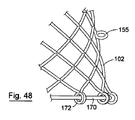
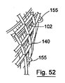
図47から50を参照すると、上記のものと同様の本発明による別の弁装置151が示されており、同様の部品には同じ参照番号が割り当てられている。この場合、弁1は、支持構造体または骨格102内に収容され、図51から53に示されているステント140の管腔に入れられる。支持構造体は、ニチノールなどの形状記憶材料から構成された比較的長さの短い(典型的には40mmの)網目を含むことができる。網目をレーザ切断によって形成することができ、かつ/または織物構造体で構成することができる。ホストステント140の管腔への展開は、図49および50に示される送達カテーテル130内での半径方向に折りたたまれた状態からの自己膨張を介する。装置151は、支持構造体102の軸方向摩擦力を大きくする特定の相互作用機構の手段によってステント140内の所定位置に保持される。図51から53は、ホストステント140との相互作用を示す。本実施形態において、支持構造体102は、その表面から垂直方向に伸びる一連のループまたは突起155を有する。これらの突起155は、図52および53に示される既存の網目と連結することによって任意のホストステント140の構造と係合する。各突起155の先端は、この場合、丸められているか、または突起155に接触し得る組織を損なわないように設計されている。支持構造体102の固有半径方向力、ならびに突起155の曲げ強度が相互作用して、支持構造体102の保持性能を有効にする。したがって、突起155の剛性または曲げ強度および支持構造体102の半径方向力を改めて、装置の連結機能および保持性能を変えることができる。
Referring to FIGS. 47 to 50, another
弁装置151は、また、遠位および近位引張糸集合体170、171によって容易に半径方向に折りたたみ可能である。遠位引張糸集合体170は、弁装置151の遠端で支持構造体102に装着されたアイレット172を通る。遠位引張糸集合体170は、引っ張ると、引張糸集合体171を内側に引っ張ることで、支持構造体102の遠端の径を小さくする接触可能な引き糸173を有する。同様に、近位引張糸集合体171は、弁装置151の近端で支持構造体102に装着されたアイレット175を通る。近位引張糸集合体171は、引っ張ると、引張糸集合体171を内側に引っ張ることで、支持構造体102の近端の径を小さくする接触可能な引き糸177を有する。弁装置151を容易に取り除くために、支持構造体102の近位および遠端を内側に引っ張るためにグラスパーなどの好適な器具を使用して、引き糸173、177を容易に把持することができる。
The
図54から63を参照すると、上記のものと同様の本発明による別の弁装置200が示されており、同様の部品には同じ参照番号が割り当てられている。この場合、弁1は、支持構造体または骨格102内に収容され、図59から62に示されているステント140の管腔に入れられる。支持構造体102は、ニチノールなどの形状記憶材料から構成された比較的長さの短い(典型的には40mmの)網目を含むことができる。網目をレーザ切断によって形成することができ、かつ/または織物構造体で構成することができる。ホストステント140の管腔への展開は、図56から61に示される送達カテーテル130内での半径方向に折りたたまれた状態からの自己膨張を介する。装置200は、支持構造体102の軸方向摩擦力を大きくする特定の相互作用機構の手段によってステント140内の所定位置に保持される。図62は、ホストステント140との相互作用を示す。本実施形態において、支持構造体102は、その表面から垂直方向に伸びる一連のループまたは突起155を有する。これらの突起155は、図62に示される既存の網目と連結することによって任意のホストステント140の構造と係合する。各突起155の先端は、この場合、丸められているか、または突起155に接触し得る組織を損なわないように設計されている。支持構造体102の固有半径方向力、ならびに突起155の曲げ強度が相互作用して、支持構造体102の保持性能を有効にする。したがって、突起155の剛性または曲げ強度および支持構造体102の半径方向力を改めて、装置の連結機能および保持性能を変えることができる。
Referring to FIGS. 54-63, another
弁装置200は、また、遠位および近位引張糸集合体170、171によって容易に半径方向に折りたたみ可能である。遠位引張糸集合体170は、弁装置200の遠端で支持構造体102に装着されたアイレット172を通る。遠位引張糸集合体170は、引っ張ると、引張糸集合体171を内側に引っ張ることで、支持構造体102の遠端の径を小さくする接触可能な引き糸173を有する。同様に、近位引張糸集合体171は、弁装置200の近端で支持構造体102に装着されたアイレット175を通る。近位引張糸集合体171は、引っ張ると、引張糸集合体171を内側に引っ張ることで、支持構造体102の近端の径を小さくする接触可能な引き糸177を有する。弁装置200を容易に取り除くために、支持構造体102の近位および遠端を内側に引っ張るためにグラスパーなどの好適な器具を使用して、引き糸173、177を容易に把持することができる。
The
装置200の場合は、支持骨格の直径が比較的均一であり、装置200の遠端201、202が先細りしていないことを注記する。ステント140の網目構造体に画定された隙間における丸い突起155の相互係合は、装置200をステント140における所定位置に保持するのに十分であることを見いだした。典型的には、膨張支持構造体102の直径は、骨格102を原位置に維持するのに役立つ所望の展開位置において、ホストステント140よりわずかに大きく、例えば1から5%大きい。
Note that in the case of the
いくつかの実例において、図63に示されているように、装置200などの本発明の装置は、例えば、置換えおよび/またはホストステント140の置換えのために、弁装置200をステント140とともに移動させるか、または装置200を引き出すことが示される場合は、半径方向に折りたたまれた状態であってよい。
In some instances, as shown in FIG. 63, a device of the present invention, such as
したがって、弁が崩壊可能であるため、突起155をホストステント140から外すことによってそれを随意に取り外すことで、ホストステント140に伴う軸方向摩擦力を除去することが可能である。
Thus, because the valve is collapsible, it is possible to remove axial frictional forces associated with the
図1から63の弁は、一部に、例えば食道癌の結果として食道に狭窄を有する患者に有用である。弁を食道の遠端の近くおよびそれが装着/展開される補綴体の遠端の近くに配置することができる。弁は、比較的短く、典型的には30mm未満、25mm未満、20mm未満、15mm未満であり、典型的には、約10.6mmの長さで外枠の直径が18mmであるか、または約11mmの長さで外枠の直径が20mmである。 The valves of FIGS. 1 to 63 are useful in part for patients who have strictures in the esophagus, for example as a result of esophageal cancer. The valve can be placed near the distal end of the esophagus and near the distal end of the prosthesis on which it is installed / deployed. The valve is relatively short, typically less than 30 mm, less than 25 mm, less than 20 mm, less than 15 mm, typically about 10.6 mm long with an outer frame diameter of 18 mm, or about The outer frame has a length of 11 mm and a diameter of 20 mm.
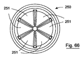
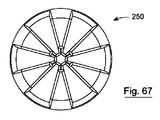
弁は、所望の数の弁葉状体を有することができ、例えば、図64から70に示されている弁250は、6つの弁葉状体251を有する。これらの弁葉状体251は、食物の流れ方向に対して垂直に配向して、さらに弁開口のより大きな伸長性を可能にする。
The valve can have any desired number of leaflets, for example, the
図71から83を参照すると、本発明による別の弁装置が示されている。装置300は、順行方向(食物摂取方向)および逆行方向(胃から口への方向)で自動的に開放することができる食道弁300を含む。
71 to 83, another valve device according to the present invention is shown. The
弁301は、図64から70の弁と類似しており、枠302を含む近位外側支持領域と、6つの弁葉状体303と、支持枠302と弁葉状体303の間に伸びる本体領域306とを含む。弁葉状体303は、内側および遠方に伸び、それぞれ遠端面303で終端する。弁葉状体303は、それぞれ、互いに60°の先端角で伸びる脚を有する。弁が常閉構成であるときに、隣接する脚の対が接合して、弁葉状体303の間の隙間を閉鎖する。
The
弁301は3つの構成を有する。第1の構成は、弁葉状体303が弁を閉鎖するように接合する常閉構成である。第2の構成は、弁葉状体脚対が順行力F1に応答して開放および離間されて、弁301を通じた流れを可能にするように、弁葉状体303が開放される順行開放構成である。第3の構成は、順行力より実質的に大きい逆行力F2に応答する逆行開放構成である。
The
弁1の様々な構成が図71から82に示されている。第1のまたは常閉構成(図71、72)において、弁葉状体303が接合する。順行力F1が弁葉状体303に加えられると、弁葉状体脚対が開放して順行流の流れを可能にする(図74、77、78)。順行力F1が除去されると、弁葉状体303は、弁体のポリマー材料の固有偏倚下で閉鎖位置に戻る(図71)。
Various configurations of the
逆行力F2が弁体に加えられる。この力は、最初に弁葉状体303を互いに押しつけ(図80)、圧力が設定値を超えると、図81に示されるように弁体が逆転する。弁が、逆行力F2に応答して完全に開放されると、弁本体(および弁葉状体303)が、図81に示されるように近接して(上方に)伸びる。これは、逆行流のバルブを通じた流れを可能にする。逆行力F2が除去されると、弁本体は、ポリマー材料の偏倚に応答して裏返ることによって本来の構成に戻ることで、図71に示されるように弁葉状体が遠方に伸びる常閉構成に戻る。
A retrograde force F2 is applied to the valve body. This force first pushes the
弁葉状体303は、接合の領域で強化される。この場合、これは、この領域におけるポリマー材料を局部的に厚くすることによって達成される。同様に、支持枠302は、ポリマー材料を局部的に厚くすることによって強化される。
The
弁葉状体303の接合領域は、典型的には1から5mmである軸方向の広がりを有する。これは、弁が常閉構成であるときに大きな界面領域にわたる弁葉状体の完全な接合を保証する。接合領域における弁葉状体の厚さは、典型的には、0.1mmから10mmである。
The junction region of the
弁体306は、全体的に凹形の外面および全体的に凸形の内面を有する。
弁300は二方弁である。近方向または遠方向から弁を開放するのに異なる力が必要である。弁300は、順方向で開放するために非常にわずかな力しか必要とせず、140ml/分の流量を可能にするに順行方向での0.7mmHgの圧力で十分である。逆行方向において、弁1は、15mmHgから40mmHg以上の圧力を保持することができる。弁の材料の特性(密度など)を変えることによって、変化する降伏圧力に対応するように弁を調整することができる。弁300は、逆行方向の圧力下に配置されると、制御可能に逆転することによってこれを達成する。
The
The
本発明の弁300は、逆行方向で完全に開放された後に、その本来の使用位置に戻る。これは、使用弁を損なうことなく達成される。
食物が逆行方向に流れることによって弁300が開放されると、弁葉状体303が開放する。弁の外面は、形状の変化に対してより大きな抵抗を有するため、逆行方向で本体を開放するのに必要な力はより大きくなる。
The
When the
弁300の機能に影響を与える重要な特性は、互いに衝突する弁葉状体脚である。弁葉状体303の幾何学的構造および長さを変えることによって、弁300を異なる圧力で逆行方向に開放させることができる。順行方向の開放は、弁葉状体の幾何学構造への依存が幾分小さく、装置を構成する材料の弾性および密度により大きく依存する。また、全直径、および弁葉状体が開放する直径は、両方向の開放力に影響を与える。
An important characteristic that affects the function of the
胃は、食道よりわずかに大きな圧力を有する(平均で12mmHg)ため、閉じた弁は、その遠端面でこの圧力を受けることになる。この遠端圧力は、遠方に伸びる面または先細りする面の閉鎖を改善することができる。しかし、文献における弁の先の実施例は、胃の圧力差を利用するために平滑面に依存していた。したがって、胃の圧力によって生成される力を最大にする唯一の手段は、遠方に伸びる面または先細りする面の長さを大きくするものであった。これは、次に、細長い構造体が食物の順行流および逆行流で封鎖されることに伴う問題を生じた。本発明は、弁構造体の長さを短く維持し、表面積対長さの比の増加を介して胃の圧力により生成される力を最大にする方法を教示する。これは、プリーツまたはヒダ(弁葉状体)を導入することによって弁の遠端面の表面積を増加させることによって達成される。 Since the stomach has a slightly greater pressure than the esophagus (on average 12 mmHg), the closed valve will experience this pressure at its distal end face. This far end pressure can improve the closure of the far extending or tapering surface. However, previous examples of valves in the literature relied on smooth surfaces to take advantage of gastric pressure differences. Thus, the only means of maximizing the force generated by gastric pressure has been to increase the length of the far-extending or tapered surface. This in turn caused problems with the elongate structures being sequestered in the forward and backward flow of food. The present invention teaches a method of keeping the length of the valve structure short and maximizing the force generated by gastric pressure through an increase in the surface area to length ratio. This is accomplished by increasing the surface area of the far end face of the valve by introducing pleats or pleats.
弁は、任意の好適な生体適合性ポリマー材料で構成されてよい。弁が上記のように機能することを可能にする特性を有する生体適合性ポリマー材料であってよい。
この弁の製造に使用される材料は、50%から3000%の伸度(%)を有する。その材料は、また、0.01から5MPaの引張強度を有する。また、その材料は、インビトロでコロニー形成を防止する抗微生物作用を有することが可能である。また、その材料は、弾性または粘弾性であり、場合によって連続気泡発泡体であり得る。その材料の密度は、0.1g/cm3から1.5g/cm3である。
The valve may be constructed of any suitable biocompatible polymer material. It may be a biocompatible polymeric material having properties that allow the valve to function as described above.
The material used to make this valve has an elongation (%) of 50% to 3000%. The material also has a tensile strength of 0.01 to 5 MPa. The material can also have an antimicrobial action to prevent colony formation in vitro. The material is also elastic or viscoelastic, and may optionally be an open cell foam. The density of the material is from 0.1 g / cm3 to 1.5 g / cm3.
本発明の弁300を任意の好適な管腔補綴体、特に食道補綴体350に装着することができる。弁の枠302は、補綴体内に装着するための装着環を提供し、例えば、図71に示される縫合糸351を使用して枠2をステント網目に縫合することによって弁300をステントに装着することができる。
The
補綴体350は、任意の好適なタイプであってよい。コーティングまたはスリーブが施されていないステント350が、図71から81に示されている。
この場合、弁300は、補綴体350の遠端に装着される。胃は、7mmHgの圧力を生成する。弁の遠端は、材料を圧縮して、既に閉鎖された弁に対する閉鎖圧力をさらに大きくするこの圧力に曝される。補綴体350は、例えば、胃噴門、すなわち胃の入口と下部食道括約筋との間の組織の領域における組織アンカー361によって容易に所定位置に固定され得るように配置される。概して、この領域における組織壁が厚くなって、補綴体350の固定が容易になる。組織アンカーは、USGIから商業的に入手可能なG−Cathシステムに使用されるものなどであってよい。
The
In this case, the
補綴体350は、長時間にわたって原位置にあるように設計される。標準的なニチノール金属ステントを用いると、ステントによって半径方向力が加えられるため、患者がその存在を認識し得る。補綴体350は、対照的に、組織アンカー361を使用して、例えば固定中にそれが原位置にとどまるのに十分に自己膨張する編組プラスチック網目で構成されてよい。ステントの網目は、網目を損傷することなく組織アンカーを受けるのに十分に開放されるべきであるが、組織アンカーの引き通しを防止するのに十分に高密度である必要がある。補綴体は、典型的には、患者に不快感を与えることなく原位置にそれを保持するために1.9Kpa未満の半径方向力を有する。
The
本実施形態による弁装置は、GERDの処理に特に有用である。弁は、食道の遠端の遠位に配置される。
弁は、比較的短く、胃の中に有意に入り込まないことに留意されたい。先行技術の「ウィンドソック」型装置は長いため、胃の内容物による詰まりをもたらし得る。さらなる材料が、当該ウィンドソック装置における毛管作用によって胃から上昇し得る。対照的に、本発明のGERD弁は、典型的には、50mm未満、40mm未満、30mm未満であり、23mmの直径に対しては典型的に約23mm長である。
The valve device according to the present embodiment is particularly useful for GERD processing. The valve is placed distal to the distal end of the esophagus.
Note that the valve is relatively short and does not penetrate significantly into the stomach. Prior art “windsock” type devices are long and can cause clogging with stomach contents. Additional material can be lifted from the stomach by capillary action in the windsock device. In contrast, GERD valves of the present invention are typically less than 50 mm, less than 40 mm, less than 30 mm, and are typically about 23 mm long for a diameter of 23 mm.
図83および84を参照すると、図71から82の装置に類似する本発明による別の装置400が示されており、同様の部品には同じ参照番号が割り当てられている。この場合、弁301は、補綴体350の遠端への弁の枠302のオーバーモールド401によって補綴体350に装着される。オーバーモールドは、補綴体350と弁枠302の間に大きな内容物領域が存在するときに軸方向の負荷を分散させるのに役立つ。
Referring to FIGS. 83 and 84, there is shown another
本発明の食道弁は、順行方向(食物摂取方向)および逆行方向(胃から口への方向)に自動的に開放することができる。
弁は二方弁である。近方向または遠方向から弁を開放するのに異なる力が必要である。弁は、順行方向で開放するために非常にわずかな力しか必要とせず、0.7mmHg程度の圧力の水が、少なくとも140ml/分の流量を可能にする。逆行方向において、弁は、30mmHg以上の圧力を保持することができる。弁の材料の特性(密度など)を変えることによって、変化する降伏圧力に対応するように弁を調整することができる。弁は、逆行方向の圧力下に配置されると、制御可能に逆転することによってこれを達成する。
The esophageal valve of the present invention can automatically open in the antegrade direction (food intake direction) and the retrograde direction (direction from stomach to mouth).
The valve is a two-way valve. Different forces are required to open the valve from the near or far direction. The valve requires very little force to open in the forward direction, and water at a pressure on the order of 0.7 mm Hg allows a flow rate of at least 140 ml / min. In the retrograde direction, the valve can hold a pressure of 30 mmHg or more. By changing the material properties (such as density) of the valve, the valve can be adjusted to accommodate changing yield pressures. When the valve is placed under retrograde pressure, it accomplishes this by controllably reversing.
本発明の弁は、逆行方向で完全に開放された後に、その本来の使用位置に戻る。これは、使用弁を損なうことなく達成される。
予め展開された食道ステントに装着するための食道弁に関して本発明を説明したが、それを、動脈または尿道を含む他の体管路、あるいは小腸と大腸の間に配置された回盲弁の代用などの胃腸系における他の箇所の弁の装着に適用することもできる。
The valve of the present invention returns to its original use position after being fully opened in the retrograde direction. This is achieved without compromising the valve used.
While the present invention has been described with respect to an esophageal valve for attachment to a pre-deployed esophageal stent, it can be substituted for other body ducts including the arteries or urethra, or ileocecal valve placed between the small and large intestines The present invention can also be applied to mounting of a valve at another location in the gastrointestinal system.
以下のセクションには、本発明の弁を製造するのに好適な一群の生体材料が記載されている。
ポリウレタン発泡体における軟質部分としてポリエーテルを使用すると、水素結合の動的強化効果により、軟質の弾性および粘弾性材料が得られることが知られている。逆に、非水素結合の疎水性軟質部分を使用すると、より硬く、より低弾性の材料が得られる。ウレタン/尿素結合を介する図85に示される当該疎水性および親水性軟質部分のブレンドは、特定の用途に適する機械特性を達成することが当該技術分野で既知である。
The following section describes a group of biomaterials suitable for producing the valves of the present invention.
It is known that when a polyether is used as a soft part in a polyurethane foam, a soft elastic and viscoelastic material can be obtained due to the dynamic strengthening effect of hydrogen bonding. Conversely, the use of non-hydrogen bonded hydrophobic soft moieties results in harder and less elastic materials. It is known in the art that the blend of hydrophobic and hydrophilic soft moieties shown in FIG. 85 via a urethane / urea bond achieves mechanical properties suitable for a particular application.
ポリウレタン材料内のウレタン結合において、酸に触媒された加水分解劣化が生じる。したがって、これらのウレタン/尿素結合は、ポリウレタン材料の「弱いリンク」である。ポリウレタン材料の固有の親水性は、吸水量の調節を介して加水分解の速度に影響を与えることがわかる。したがって、当該材料は、胃環境(強酸性水性環境)での使用に適さない。 Acid-catalyzed hydrolysis degradation occurs in urethane bonds within the polyurethane material. These urethane / urea bonds are therefore “weak links” of the polyurethane material. It can be seen that the inherent hydrophilicity of the polyurethane material affects the rate of hydrolysis through adjustment of water absorption. Therefore, the material is not suitable for use in a stomach environment (strongly acidic aqueous environment).
したがって、いくつかの実施形態において、本発明は、胃環境において生体模倣的および加水分解安定的なマルチブロックコポリマーを提供する。当該マルチブロックコポリマーは、式Iを有する。 Accordingly, in some embodiments, the present invention provides multi-block copolymers that are biomimetic and hydrolytically stable in the gastric environment. The multi-block copolymer has the formula I.

[式中、 [Where:
![]()
![]()
はそれぞれ、ウレタン結合または尿素結合に対する結合点を表し;
XおよびYはそれぞれ、独立して、ポリエーテル、ポリエステル、ポリカーボネートまたはフルオロポリマーの1種または複数種から形成されたポリマー鎖またはコポリマー鎖であり;
R1、R2、R3、R4、R5およびR6はそれぞれ、R、OR、−CO2R、フッ化炭化水素、ポリエーテル、ポリエステルまたはフルオロポリマーの1種または複数種から独立して選択され;
Rはそれぞれ、独立して、水素、場合によって置換されたC1−20脂肪族基、またはフェニル、8〜10員二環式アリール、窒素、酸素または硫黄から独立して選択される1〜2個のヘテロ原子を有する4〜8員単環式飽和または部分不飽和複素環式環、あるいは窒素、酸素または硫黄から独立して選択される1〜4個のヘテロ原子を有する5〜6員単環式または8〜10員二環式ヘテロアリール基から選択される場合によって置換された基であり;
m、nおよびpはそれぞれ、独立して、2から100であり;
L1およびL2はそれぞれ、独立して、炭化水素鎖の1〜4個のメチレン単位が、−O−、−S−、−N(R)−、−C(O)−、−C(O)N(R)−、−N(R)C(O)−、−SO2−、−SO2N(R)−、−N(R)SO2、−OC(O)−、−C(O)Oによって場合によって、かつ独立して置換された二価のC1−20炭化水素鎖、あるいは二価のシクロアルキレン、アリーレン、ヘテロシクレンまたはヘテロアリーレンであり、但し、L1もL2も尿素またはウレタン部分を含まない。]
2.定義
本発明の化合物は、以上に概ね記載されているものを含み、本明細書に開示されているクラス、サブクラスおよび種によってさらに例示される。本明細書に使用されているように、他に指定する場合を除いて、以下の定義が適用されることになる。本発明の目的のために、化学元素は、元素周期律表、CASバージョン、化学・物理ハンドブック、第75版に従って特定される。また、有機化学の一般原理は、それらの開示内容全体が参照により本明細書に組み込まれている「有機化学」、Thomas Sorrell University Science Books,Sausalito:1999、および「マーチ有機化学(March’s Advanced Organic Chemistry)」、第5版、編集:Smith,M.B.and March,J.,John Wiley & Sons,New York:2001に記載されている。
Each represents a point of attachment to a urethane or urea bond;
X and Y are each independently a polymer chain or copolymer chain formed from one or more of a polyether, polyester, polycarbonate or fluoropolymer;
R 1 , R 2 , R 3 , R 4 , R 5 and R 6 are each independently one or more of R, OR, —CO 2 R, fluorinated hydrocarbons, polyethers, polyesters or fluoropolymers. Selected;
Each R is independently selected from hydrogen, optionally substituted C 1-20 aliphatic group, or phenyl, 8-10 membered bicyclic aryl, nitrogen, oxygen, or sulfur 1-2 4 to 8 membered monocyclic saturated or partially unsaturated heterocyclic ring having 1 heteroatom, or 5 to 6 membered single having 1 to 4 heteroatoms independently selected from nitrogen, oxygen or sulfur An optionally substituted group selected from cyclic or 8-10 membered bicyclic heteroaryl groups;
m, n and p are each independently 2 to 100;
L 1 and L 2 each independently represent from 1 to 4 methylene units of the hydrocarbon chain —O—, —S—, —N (R) —, —C (O) —, —C ( O) N (R) -, - N (R) C (O) -, - SO 2 -, - SO 2 N (R) -, - N (R) SO 2, -OC (O) -, - C (O) a divalent C 1-20 hydrocarbon chain optionally and independently substituted by O, or a divalent cycloalkylene, arylene, heterocyclene or heteroarylene, provided that neither L 1 nor L 2 Does not contain urea or urethane moieties. ]
2. Definitions Compounds of the invention include those generally described above and are further exemplified by the classes, subclasses and species disclosed herein. As used herein, the following definitions shall apply unless otherwise specified. For the purposes of the present invention, chemical elements are identified according to the Periodic Table of Elements, CAS version, Chemistry / Physics Handbook, 75th edition. Also, the general principles of organic chemistry are described in “Organic Chemistry”, Thomas Sorell University Science Books, Sausalito: 1999, and “March's Advanced”, the entire disclosures of which are incorporated herein by reference. Organic Chemistry) ", 5th edition, edited by Smith, M .; B. and March, J.A. , John Wiley & Sons, New York: 2001.
本明細書に記載されているように、本発明の化合物は、以上に概ね例示されている、または本発明の特定のクラス、サブクラスおよび種によって例示されている1つまたは複数の置換基で場合によって置換されていてよい。「場合によって置換された」という表現は、「置換または非置換の」という表現と区別なく使用されることが理解される。概して、「置換された」という用語は、その前に「場合によって」という用語があるか否かにかかわらず、所定の構造の水素基が指定の置換基の基で置き換えられていることを指す。他に指定される場合を除いて、場合によって置換された基は、基の各置換可能位置に置換基を有することができ、所定の構造における1つを超える位置が、特定の基から選択される1つを超える置換基で置換され得るときは、置換基は、あらゆる位置において同一であっても異なっていてもよい。本発明により考えられる置換基の組合せは、好ましくは、安定化合物または化学的に実現可能な化合物の形成をもたらすものである。「安定な」という用語は、本明細書に使用されているように、それらの製造、検出、好ましくはそれらの回収、精製、および本明細書に開示されている1つまたは複数の目的のための使用を可能にする条件に曝露されても実質的に変化しない化合物を指す。いくつかの実施形態において、安定化合物または化学的に実現可能な化合物は、少なくとも1週間にわたって水分または他の化学反応条件の不在下で40℃以下の温度に維持されても実質的に変化しない化合物を指す。 As described herein, compounds of the present invention may be substituted with one or more substituents as generally exemplified above or exemplified by certain classes, subclasses and species of the present invention. May be substituted. It is understood that the expression “optionally substituted” is used interchangeably with the expression “substituted or unsubstituted”. In general, the term “substituted” refers to the fact that a hydrogen group of a given structure has been replaced with a group of specified substituents, whether or not preceded by the term “optionally”. . Except where otherwise specified, an optionally substituted group can have a substituent at each substitutable position of the group, and more than one position in a given structure is selected from the particular group. When more than one substituent can be substituted, the substituents may be the same or different at any position. Combinations of substituents envisioned by this invention are preferably those that result in the formation of stable or chemically feasible compounds. The term “stable” as used herein for their manufacture, detection, preferably their recovery, purification, and one or more purposes disclosed herein. Refers to compounds that do not substantially change upon exposure to conditions that allow their use. In some embodiments, the stable compound or chemically feasible compound is a compound that does not substantially change when maintained at a temperature of 40 ° C. or lower in the absence of moisture or other chemical reaction conditions for at least one week. Point to.
「脂肪族」または「脂肪族基」という用語は、本明細書に使用されているように、直鎖(すなわち非分枝状)、分枝状または環式(縮合、架橋およびスピロ縮合多環式を含む)であってよく、完全飽和であるか、または1つまたは複数の不飽和単位を含むことができるが、芳香族でない炭化水素部分を表す。他に指定する場合を除いて、脂肪族基は、1〜20個の炭素原子を含む。いくつかの実施形態において、脂肪族基は、1〜10個の炭素原子を含む。他の実施形態において、脂肪族基は、1〜8個の炭素原子を含む。さらに他の実施形態において、脂肪族基は、1〜6個の炭素原子を含み、さらに他の実施形態において、脂肪族基は1〜4個の炭素原子を含む。好適な脂肪族基としては、直鎖状または分枝状のアルキル基、アルケニル基およびアルキニル基、ならびに(シクロアルキル)アルキル、(シクロアルケニル)アルキルまたは(シクロアルキル)アルケニルなどのそれらの混成体が挙げられるが、それらに限定されない。 The term “aliphatic” or “aliphatic group” as used herein refers to straight chain (ie unbranched), branched or cyclic (fused, bridged and spiro-fused polycycles). Represents a hydrocarbon moiety that is fully saturated or can contain one or more unsaturated units, but is not aromatic. Except where otherwise specified, aliphatic groups contain 1-20 carbon atoms. In some embodiments, aliphatic groups contain 1-10 carbon atoms. In other embodiments, aliphatic groups contain 1-8 carbon atoms. In still other embodiments, aliphatic groups contain 1-6 carbon atoms, and in yet other embodiments aliphatic groups contain 1-4 carbon atoms. Suitable aliphatic groups include linear or branched alkyl groups, alkenyl groups and alkynyl groups, and hybrids thereof such as (cycloalkyl) alkyl, (cycloalkenyl) alkyl or (cycloalkyl) alkenyl. But not limited to.
「低級アルキル」という用語は、C1−4の直鎖状または分枝状アルキル基を指す。例示的な低級アルキル基は、メチル、エチル、プロピル、イソプロピル、ブチル、イソブチルおよびtert−ブチル。 The term “lower alkyl” refers to a C 1-4 straight or branched alkyl group. Exemplary lower alkyl groups are methyl, ethyl, propyl, isopropyl, butyl, isobutyl and tert-butyl.
「低級ハロアルキル」という用語は、1個または複数個のハロゲン原子で置換されたC1−4の直鎖状または分枝状アルキル基を指す。
「ヘテロ原子」という用語は、酸素、硫黄、窒素、リンまたはケイ素の1種または複数種を指す(窒素、硫黄、リンまたはケイ素の任意の酸化形態;任意の塩基性窒素の四級化形態;または複素環式環の置換可能窒素、例えばN(3,4−ジヒドロ−2H−ピロリルなどの)、NH(ピロリジニルなどの)、またはNR+(N置換ピロリジニルなどの)を含む)。
The term “lower haloalkyl” refers to a C 1-4 straight or branched alkyl group substituted with one or more halogen atoms.
The term “heteroatom” refers to one or more of oxygen, sulfur, nitrogen, phosphorus or silicon (any oxidized form of nitrogen, sulfur, phosphorus or silicon; quaternized form of any basic nitrogen; Or a substitutable nitrogen on a heterocyclic ring, including N (such as 3,4-dihydro-2H-pyrrolyl), NH (such as pyrrolidinyl), or NR + (such as N-substituted pyrrolidinyl)).
「不飽和」という用語は、本明細書に使用されているように、部分が1つまたは複数の不飽和単位を有することを意味する。
本明細書に使用されているように、「二価のC1−8[またはC1−6]飽和または不飽和直鎖状または分枝状炭化水素鎖」という用語は、本明細書に定義されているように直鎖状または分枝状である二価のアルキレン鎖、アルケニレン鎖およびアルキニレン鎖を指す。
The term “unsaturated”, as used herein, means that a moiety has one or more unsaturated units.
As used herein, the term “divalent C 1-8 [or C 1-6 ] saturated or unsaturated linear or branched hydrocarbon chain” is defined herein. As used herein, it refers to a divalent alkylene chain, alkenylene chain and alkynylene chain which are linear or branched.
「アルキレン」という用語は、二価アルキル基を指す。「アルキレン鎖」は、ポリメチレン基、すなわち−(CH2)n−[nは、正の整数、好ましくは1から6、1から4、1から3、1から2、または2から3である。]である。置換アルキレン鎖は、1つまたは複数のメチレン水素原子が置換基で置換されたポリメチレン基である。好適な置換基としては、置換脂肪族基について以下に記載されているものが挙げられる。 The term “alkylene” refers to a divalent alkyl group. An “alkylene chain” is a polymethylene group, ie — (CH 2 ) n — [n is a positive integer, preferably 1 to 6, 1 to 4, 1 to 3, 1 to 2, or 2 to 3. ]. A substituted alkylene chain is a polymethylene group in which one or more methylene hydrogen atoms are replaced with a substituent. Suitable substituents include those described below for substituted aliphatic groups.
「アルケニレン」は、二価アルケニル基を指す。置換アルケニレン鎖は、1個または複数個の水素原子が置換基で置換された少なくとも1つの二重結合を含むポリメチレン基である。好適な置換基としては、置換脂肪族基について以下に記載されているものが挙げられる。 “Alkenylene” refers to a divalent alkenyl group. A substituted alkenylene chain is a polymethylene group containing at least one double bond in which one or more hydrogen atoms are replaced by a substituent. Suitable substituents include those described below for substituted aliphatic groups.
「ハロゲン」という用語は、F、Cl、BrまたはIを指す。
単独で、または「アラルキル」、「アラルコキシ」もしくは「アリールオキシアルキル」などのより大きい部分の一部として使用される「アリール」という用語は、系における少なくとも1つの環が芳香族であり、系における各環が3から7個の環員を含む、計5から14個の環員を有する単環式または二環式環系を指す。「アリール」という用語を「アリール環」という用語と区別なく使用することができる。
The term “halogen” refers to F, Cl, Br or I.
The term “aryl” used alone or as part of a larger moiety such as “aralkyl”, “aralkoxy” or “aryloxyalkyl” means that at least one ring in the system is aromatic and Refers to a monocyclic or bicyclic ring system having a total of 5 to 14 ring members, each ring containing 3 to 7 ring members. The term “aryl” can be used interchangeably with the term “aryl ring”.
本明細書に記載されているように、本発明の化合物は、「場合によって置換された」部分を含むことができる。概して、「置換された」という用語は、その前に「場合によって」という用語があるか否かにかかわらず、指定部分の1つまたは複数の水素が好適な置換基で置換されていることを意味する。他に指定される場合を除いて、「場合によって置換された」基は、基の各置換可能位置に置換基を有することができ、所定の構造における1つを超える位置が、特定の基から選択される1つを超える置換基で置換され得るときは、置換基は、あらゆる位置において同一であっても異なっていてもよい。本発明により考えられる置換基の組合せは、好ましくは、安定化合物または化学的に実現可能な化合物の形成をもたらすものである。「安定な」という用語は、本明細書に使用されているように、それらの製造、検出、一部の実施形態ではそれらの回収、精製、および本明細書に開示されている1つまたは複数の目的のための使用を可能にする条件に曝露されても実質的に変化しない化合物を指す。 As described herein, compounds of the present invention can include “optionally substituted” moieties. In general, the term “substituted” means that one or more hydrogens in the specified moiety has been replaced with a suitable substituent, regardless of whether there is the term “optionally” preceding it. means. Except as otherwise specified, an “optionally substituted” group can have a substituent at each substitutable position of the group such that more than one position in a given structure can be When substituted with more than one selected substituent, the substituents may be the same or different at any position. Combinations of substituents envisioned by this invention are preferably those that result in the formation of stable or chemically feasible compounds. The term “stable” as used herein refers to their manufacture, detection, in some embodiments their recovery, purification, and one or more disclosed herein. Refers to a compound that does not substantially change upon exposure to conditions that allow its use for that purpose.
「場合によって置換された」基の置換可能炭素原子上の好適な一価置換基は、独立して、ハロゲン;−(CH2)0−4Ro;−(CH2)0−4ORo;−O−(CH2)0−4C(O)ORo;−(CH2)0−4CH(ORo)2;−(CH2)0−4SRo;Roで置換されていてよい−(CH2)0−4Ph;Roで置換されていてよい−(CH2)0−4O(CH2)0−1Ph;Roで置換されていてよい−CH=CHPh;−NO2;−CN;−N3;−(CH2)0−4N(Ro)2;−(CH2)0−4N(Ro)C(O)Ro;−N(Ro)C(S)Ro;−(CH2)0−4N(Ro)C(O)NRo 2;−N(Ro)C(S)NRo 2;−(CH2)0−4N(Ro)C(O)ORo;−N(Ro)N(Ro)C(O)Ro;−N(Ro)N(Ro)C(O)NRo 2;−N(Ro)N(Ro)C(O)ORo;−(CH2)0−4C(O)Ro;−C(S)Ro;−(CH2)0−4C(O)ORo;−(CH2)0−4C(O)SRo;−(CH2)0−4C(O)OSiRo 3;−(CH2)0−4OC(O)Ro;−OC(O)(CH2)0−4SR−、SC(S)SRo;−(CH2)0−4SC(O)Ro;−(CH2)0−4C(O)NRo 2;−C(S)NRo 2;−C(S)SRo;−SC(S)SRo;−(CH2)0−4OC(O)NRo 2;−C(O)N(ORo)Ro;−C(O)C(O)Ro;−C(O)CH2C(O)Ro;−C(NORo)Ro;−(CH2)0−4SSRo;−(CH2)0−4S(O)2Ro;−(CH2)0−4S(O)2ORo;−(CH2)0−4OS(O)2Ro;−S(O)2NRo 2;−(CH2)0−4S(O)Ro;−N(Ro)S(O)2NRo 2;−N(Ro)S(O)2Ro;−N(ORo)Ro;−C(NH)NRo 2;−P(O)2Ro;−P(O)Ro 2;−OP(O)Ro 2;−OP(O)(ORo)2;SiRo 3;−(C1−4直鎖状または分枝状アルキレン)O−N(Ro)2;または−(C1−4直鎖状または分枝状アルキレン)C(O)O−N(Ro)2であり、Roはそれぞれ、以下に定義されるように置換されていてよく、独立して、水素、C1−6脂肪族、−CH2Ph、−O(CH2)0−1Ph、または窒素、酸素もしくは硫黄から独立して選択される0〜4個のヘテロ原子を有する5〜6員の飽和、部分不飽和もしくはアリール環であり、あるいは上記定義にかかわらず、2つの独立したRo基は、それらの介在原子と一緒になって、以下に定義されるように置換されていてよい、窒素、酸素もしくは硫黄から独立して選択される0〜4個のヘテロ原子を有する3〜12員の飽和、部分不飽和もしくはアリール単環式もしくは二環式環を形成する。
Suitable monovalent substituents on a substitutable carbon atom of an “optionally substituted” group are independently halogen; — (CH 2 ) 0-4 R o ; — (CH 2 ) 0-4 OR o ; -O- (CH 2) 0-4 C (O) OR o ;-( CH 2) 0-4 CH (OR o) 2 ;-( CH 2) 0-4 SR o; substituted with R o good Te - (CH 2) 0-4 Ph; R o with optionally substituted - (CH 2) 0-4 O ( CH 2) 0-1 Ph; may be optionally substituted with R o -CH = CHPh ; -NO 2; -CN; -N 3 ;-( CH 2) 0-4 N (R o) 2 ;-( CH 2) 0-4 N (R o) C (O) R o; -N ( R o) C (S) R o ;-( CH 2) 0-4 N (R o) C (O) NR o 2; -N (R o) C (S) NR o 2 ;-( CH 2 0-4 N (R o) C ( O) OR o; -N (R o) N (R o) C (O) R o; -N (R o) N (R o) C (O) NR o 2 ; -N (R o ) N (R o ) C (O) OR o ;-( CH 2 ) 0-4 C (O) R o ; -C (S) R o ;-( CH 2 ) 0- 4 C (O) OR o ;-( CH 2) 0-4 C (O) SR o ;-( CH 2) 0-4 C (O) OSiR o 3 ;-( CH 2) 0-4 OC (O ) R o; -OC (O) (CH 2) 0-4 SR-, SC (S) SR o ;-( CH 2) 0-4 SC (O) R o ;-( CH 2) 0-4 C (O) NR o 2; -C (S) NR o 2; -C (S) SR o; -SC (S) SR o ;-( CH 2) 0-4 OC (O) NR o 2; -C (O) N (OR o ) R o ; -C (O) C (O) R o; -C (O) CH 2 C (O) R o; -C (NOR o) R o ;-( CH 2) 0-4 SSR o ;-( CH 2) 0-4 S (O) 2 R o ;-( CH 2) 0-4 S (O) 2 OR o ;-( CH 2) 0-4 OS (O) 2 R o; -S (O) 2 NR o 2 ;-( CH 2) 0-4 S (O) R o ; -N (R o ) S (O) 2 NR o 2 ; -N (R o ) S (O) 2 R o ; -N (OR o ) R o ; (NH) NR o 2 ;-P ( O) 2 R o ;-P (O)
Ro(2つの独立したRo基をそれらの介在原子と一緒にすることによって形成された環)上の好適な一価置換基は、独立して、ハロゲン、−(CH2)0−2R●、−(ハロR●)、−(CH2)0−2OH、−(CH2)0−2OR●、−(CH2)0−2CH(OR●)2;−O(ハロR●)、−CN、−N3、−(CH2)0−2C(O)R●、−(CH2)0−2C(O)OH、−(CH2)0−2C(O)OR●、−(CH2)0−2SR●、−(CH2)0−2SH、−(CH2)0−2NH2、−(CH2)0−2NHR●、−(CH2)0−2NR● 2、−NO2、−SiR● 3、−OSiR● 3、−C(O)SR●、−(C1−4直鎖状または分枝状アルキレン)C(O)OR●、または−SSR●であり、R●はそれぞれ、非置換であるか、または「ハロ」が先行する場合は、1つまたは複数のハロゲンのみで置換されており、C1−4脂肪族、−CH2Ph、−O(CH2)0−1Ph、または窒素、酸素もしくは硫黄から独立して選択される0〜4個のヘテロ原子を有する5〜6員の飽和、部分不飽和もしくはアリール環から独立して選択される。Roの飽和炭素原子上の好適な二価置換基は、=Oおよび=Sを含む。
Suitable monovalent substituents on R o (ring formed by combining two independent R o groups with their intervening atoms) are independently halogen, — (CH 2 ) 0-2 R ●, - (halo R ●), - (CH 2 ) 0-2 OH, - (CH 2) 0-2 OR ●, - (CH 2) 0-2 CH (OR ●) 2; -O ( halo R ● ), —CN, —N 3 , — (CH 2 ) 0-2 C (O) R ● , — (CH 2 ) 0-2 C (O) OH, — (CH 2 ) 0-2 C ( O) OR ● , — (CH 2 ) 0-2 SR ● , — (CH 2 ) 0-2 SH, — (CH 2 ) 0-2 NH 2 , — (CH 2 ) 0-2 NHR ● , — ( CH 2) 0-2 NR ● 2, -
「場合によって置換された」基の飽和炭素原子上の好適な二価置換基は、=O、=S、=NNR* 2、=NNHC(O)R*、=NNHC(O)OR*、=NNHS(O)2R*、=NR*、=NOR*、−O(C(R* 2))2−3O−または−S(C(R* 2))2−3S−を含み、それぞれの独立したR*基は、水素、以下に定義されているように置換されていてよいC1−6脂肪族、または窒素、酸素もしくは硫黄から独立して選択される0〜4個のヘテロ原子を有する5〜6員の飽和、部分不飽和もしくはアリール環窒素、酸素もしくは硫黄から独立して選択される0〜4個のヘテロ原子を有する5〜6員の飽和、部分不飽和もしくはアリール環を含む。「場合によって置換された」基の近隣の置換可能炭素に結合する好適な二価置換基は、−O(CR* 2)2−3O−を含み、それぞれの独立したR*基は、水素、以下に定義されているように置換されていてよいC1−6脂肪族、または窒素、酸素もしくは硫黄から独立して選択される0〜4個のヘテロ原子を有する非置換の5〜6員の飽和、部分不飽和もしくはアリール環から選択される。 Suitable divalent substituents on the saturated carbon atom of the “optionally substituted” group are ═O, ═S, ═NNR * 2 , ═NNHC (O) R * , ═NNHC (O) OR * , ═ NNHS (O) 2 R *, = NR *, = NOR *, -O (C (R * 2)) 2-3 O- or -S (C (R * 2) ) 2-3 comprises S-, Each independent R * group is hydrogen, C 1-6 aliphatic optionally substituted as defined below, or 0-4 heterogeneously selected from nitrogen, oxygen or sulfur. 5-6 membered saturated, partially unsaturated or aryl rings having atoms 5-6 membered saturated, partially unsaturated or aryl rings having 0-4 heteroatoms independently selected from nitrogen, oxygen or sulfur including. Suitable divalent substituents attached to a substitutable carbon adjacent to an “optionally substituted” group include —O (CR * 2 ) 2-3 O—, wherein each independent R * group is hydrogen C 1-6 aliphatic optionally substituted as defined below, or unsubstituted 5-6 members having 0-4 heteroatoms independently selected from nitrogen, oxygen or sulfur Selected from saturated, partially unsaturated or aryl rings.
R*の脂肪族基上の好適な置換基は、ハロゲン、−R●、−(ハロR●)、−OH、−OR●、−O(ハロR●)、−CN、−C(O)OH、−C(O)OR●、−NH2、−NHR●、−NR● 2または−NO2を含み、R●はそれぞれ、非置換であるか、または「ハロ」が先行する場合は、1つまたは複数のハロゲンのみで置換されており、独立して、C1−4脂肪族、−CH2Ph、−O(CH2)0−1Ph、または窒素、酸素もしくは硫黄から独立して選択される0〜4個のヘテロ原子を有する5〜6員の飽和、部分不飽和もしくはアリール環である。 Suitable substituents on the aliphatic group of R * are halogen, —R ● , — (halo R ● ), —OH, —OR ● , —O (halo R ● ), —CN, —C (O). OH, —C (O) OR ● , —NH 2 , —NHR ● , —NR ● 2 or —NO 2 , where each R ● is unsubstituted or preceded by “halo” Substituted solely with one or more halogens, independently from C 1-4 aliphatic, —CH 2 Ph, —O (CH 2 ) 0-1 Ph, or independently from nitrogen, oxygen or sulfur 5-6 membered saturated, partially unsaturated or aryl rings having 0-4 heteroatoms selected.
「場合によって置換された」基の置換可能窒素上の好適な置換基は、−R+、−NR+ 2、−C(O)R+、−C(O)OR+、−C(O)C(O)R+、−C(O)CH2C(O)R+、−S(O)2R+、−S(O)2NR+ 2、−C(S)NR+ 2、−C(NH)NR+ 2または−N(R+)S(O)2R+を含み、R+はそれぞれ、独立して、水素、以下に定義されているように置換されていてよいC1−6脂肪族、非置換−OPh、または窒素、酸素もしくは硫黄から独立して選択される0〜4個のヘテロ原子を有する非置換の5〜6員の飽和、部分不飽和もしくはアリール環であるか、あるいは上記定義にかかわらず、2つの独立したRo基は、それらの介在原子と一緒になって、窒素、酸素もしくは硫黄から独立して選択される0〜4個のヘテロ原子を有する非置換の3〜12員の飽和、部分不飽和もしくはアリール単環式もしくは二環式環を形成する。 Suitable substituents on the substitutable nitrogen of the “optionally substituted” group are —R + , —NR + 2 , —C (O) R + , —C (O) OR + , —C (O). C (O) R +, -C (O) CH 2 C (O) R +, -S (O) 2 R +, -S (O) 2 NR + 2, -C (S) NR + 2, - C comprises (NH) NR + 2 or -N (R +) S (O ) 2 R +, respectively R + is independently hydrogen, or C 1 which are optionally substituted as defined below -6 aliphatic, unsubstituted -OPh, or an unsubstituted 5-6 membered saturated, partially unsaturated or aryl ring having 0-4 heteroatoms independently selected from nitrogen, oxygen or sulfur Or, regardless of the above definition, two independent R o groups, together with their intervening atoms, can be combined with nitrogen, oxygen or It forms an unsubstituted 3-12 membered saturated, partially unsaturated or aryl monocyclic or bicyclic ring having 0-4 heteroatoms independently selected from sulfur.
R+の脂肪族基上の好適な置換基は、独立して、ハロゲン、−R●、−(ハロR●)、−OH、−OR●、−O(ハロR●)、−CN、−C(O)OH、−C(O)OR●、−NH2、−NHR●、−NR● 2または−NO2であり、R●はそれぞれ、非置換であるか、または「ハロ」が先行する場合は、1つまたは複数のハロゲンのみで置換されており、独立して、C1−4脂肪族、−CH2Ph、−O(CH2)0−1Ph、または窒素、酸素もしくは硫黄から独立して選択される0〜4個のヘテロ原子を有する5〜6員の飽和、部分不飽和もしくはアリール環である。 Suitable substituents on the aliphatic group for R + are independently halogen, —R ● , — (halo R ● ), —OH, —OR ● , —O (halo R ● ), —CN, — C (O) OH, —C (O) OR ● , —NH 2 , —NHR ● , —NR ● 2 or —NO 2 , where R ● is each unsubstituted or preceded by “halo” When substituted, it is substituted with only one or more halogens and is independently C 1-4 aliphatic, —CH 2 Ph, —O (CH 2 ) 0-1 Ph, or nitrogen, oxygen or sulfur. A 5-6 membered saturated, partially unsaturated or aryl ring having 0-4 heteroatoms independently selected from
3.例示的実施形態の説明
A.マルチブロックコポリマー
以上に概ね定義されているように、本発明の一実施形態は、式I:
3. Description of Exemplary Embodiments A. Multiblock Copolymers As generally defined above, one embodiment of the present invention is a compound of formula I:
のトリブロックコポリマーであって、該コポリマーは、ウレタン結合および/または尿素結合の間で(すなわち、 Wherein the copolymer is between urethane and / or urea bonds (ie,
![]()
![]()
で示される結合で)化学的に散在(結合)しており、X、Y、m、n、p、L1、L2、R1、R2、R3、R4、R5およびR6はそれぞれ、本明細書に定義および記載されている通りであるトリブロックコポリマーを提供する。 X, Y, m, n, p, L 1 , L 2 , R 1 , R 2 , R 3 , R 4 , R 5 and R 6. Each provide a triblock copolymer as defined and described herein.
以上に概ね定義されているように、式IのX基およびY基はそれぞれ、独立して、ポリエーテル、ポリエステル、ポリカーボネートおよびフルオロポリマーの1種または複数種から形成されたポリマー鎖またはコポリマー鎖である。 As generally defined above, the X and Y groups of formula I are each independently a polymer chain or copolymer chain formed from one or more of polyethers, polyesters, polycarbonates and fluoropolymers. is there.
Xおよび/またはYによって表されるポリマー鎖またはコポリマー鎖の例としては、ポリ(エチレンオキシド)、ポリ(ジフルオロメチルエチレンオキシド)、ポリ(トリフルオロメチルエチレンオキシド)、ポリ(プロピレンオキシド)、ポリ(ジフルオロメチルプロピレンオキシド)、ポリ(プロピレンオキシド)、ポリ(トリフルオロメチルプロピレンオキシド)、ポリ(ブチレンオキシド)、ポリ(テトラメチレンエーテルグリコール)、ポリ(テトラヒドロフラン)、ポリ(オキシメチレン)、ポリ(エーテルケトン)、ポリ(エーテルエーテルケトン)およびそれらのコポリマー、ポリ(ジメチルシロキサン)、ポリ(ジエチルシロキサン)および高級アルキルシロキサン、ポリ(メチルフェニルシロキサン)、ポリ(ジフェニルシロキサン)、ポリ(メチルジ−フルオロエチルシロキサン)、ポリ(メチルトリフルオロエチルシロキサン)、ポリ(フェニルジフルオロエチルシロキサン)、ポリ(フェニルトリフルオロエチルシロキサン)およびそれらのコポリマー、ポリ(エチレンテレフタレート)(PET)、ポリ(エチレンテレフタレートアイオノマー)(PETI)、ポリ(エチレンナフタレート)(PEN)、ポリ(メチレンナフタレート)(PTN)、ポリ(ブチレンテラファレート)(PBT)、ポリ(ブチレンナフタレート)(PBN)、ポリカーボネートが挙げられる。一部の実施形態において、本発明は、ポリウレタン/尿素発泡体の予備形成軟質部を提供する。 Examples of polymer chains or copolymer chains represented by X and / or Y include poly (ethylene oxide), poly (difluoromethylethylene oxide), poly (trifluoromethylethylene oxide), poly (propylene oxide), poly (difluoromethylpropylene) Oxide), poly (propylene oxide), poly (trifluoromethylpropylene oxide), poly (butylene oxide), poly (tetramethylene ether glycol), poly (tetrahydrofuran), poly (oxymethylene), poly (ether ketone), poly (Ether ether ketone) and copolymers thereof, poly (dimethylsiloxane), poly (diethylsiloxane) and higher alkyl siloxanes, poly (methylphenylsiloxane), poly (diphenyl) Siloxane), poly (methyldi-fluoroethylsiloxane), poly (methyltrifluoroethylsiloxane), poly (phenyldifluoroethylsiloxane), poly (phenyltrifluoroethylsiloxane) and copolymers thereof, poly (ethylene terephthalate) (PET) , Poly (ethylene terephthalate ionomer) (PETI), poly (ethylene naphthalate) (PEN), poly (methylene naphthalate) (PTN), poly (butylene teraphthalate) (PBT), poly (butylene naphthalate) (PBN) ), Polycarbonate. In some embodiments, the present invention provides a pre-formed soft part of a polyurethane / urea foam.
いくつかの実施形態において、Xはポリエーテルであり、Yはポリエーテルである。より具体的には、1つの実例において、XおよびYは、ともにポリ(プロピレンオキシド)である。 In some embodiments, X is a polyether and Y is a polyether. More specifically, in one example, X and Y are both poly (propylene oxide).
一部の実施形態において、mおよびpは、それぞれ独立して2から50であり、nは2から20である。いくつかの実施形態において、mおよびpは、それぞれ独立して2から30であり、nは2から20である。 In some embodiments, m and p are each independently 2 to 50 and n is 2 to 20. In some embodiments, m and p are each independently 2 to 30 and n is 2 to 20.
以上に概ね定義されているように、R1、R2、R3、R4、R5およびR6はそれぞれ、R、OR、−CO2R、フッ化炭化水素、ポリエーテル、ポリエステルまたはフルオロポリマーの1種または複数種から独立して選択される。いくつかの実施形態において、R1、R2、R3、R4、R5およびR6の1種または複数種は−CO2Rである。いくつかの実施形態において、R1、R2、R3、R4、R5およびR6の1種または複数種は−CO2Rであり、Rはそれぞれ、独立して、場合によって置換されたC1−6脂肪族基である。一部の実施形態において、R1、R2、R3、R4、R5およびR6の1種または複数種は−CO2Rであり、Rはそれぞれ、独立して、非置換C1−6アルキル基である。例示的な当該基は、メタン酸またはエタン酸、ならびにメタクリル酸および他のアクリル酸を含む。 As generally defined above, R 1 , R 2 , R 3 , R 4 , R 5 and R 6 are each R, OR, —CO 2 R, fluorinated hydrocarbon, polyether, polyester or fluoro. It is independently selected from one or more of the polymers. In some embodiments, one or more of R 1 , R 2 , R 3 , R 4 , R 5 and R 6 is —CO 2 R. In some embodiments, one or more of R 1 , R 2 , R 3 , R 4 , R 5 and R 6 is —CO 2 R, and each R is independently and optionally substituted. Or a C 1-6 aliphatic group. In some embodiments, one or more of R 1 , R 2 , R 3 , R 4 , R 5 and R 6 is —CO 2 R, and each R is independently an unsubstituted C 1. It is a -6 alkyl group. Exemplary such groups include methanoic acid or ethanoic acid, and methacrylic acid and other acrylic acids.
一部の実施形態において、R1、R2、R3、R4、R5およびR6の1種または複数種は、独立してRである。いくつかの実施形態において、R1、R2、R3、R4、R5およびR6の1種または複数種は、場合によって置換されたC1−6脂肪族基である。一部の実施形態において、R1、R2、R3、R4、R5およびR6の1種または複数種は、場合によって置換されたC1−6アルキルである。他の実施形態において、R1、R2、R3、R4、R5およびR6の1種または複数種は、フェニル、8〜10員の二環式アリール、窒素、酸素もしくは硫黄から独立して選択される1〜2個のヘテロ原子を有する4〜8員の単環式飽和もしくは部分不飽和複素環式環、あるいは窒素、酸素もしくは硫黄から独立して選択される1〜4個のヘテロ原子を有する5〜6員の単環式または8〜10員の二環式ヘテロアリール基から選択される場合によって置換された基である。例示的な当該R1、R2、R3、R4、R5およびR6基としては、メチル、エチル、プロピル、イソプロピル、シクロプロピル、ブチル、イソブチル、シクロブチル、フェニル、ピリジル、モルホリニル、ピロリジニル、イミダゾリルおよびシクロヘキシルが挙げられる。 In some embodiments, one or more of R 1 , R 2 , R 3 , R 4 , R 5 and R 6 is independently R. In some embodiments, one or more of R 1 , R 2 , R 3 , R 4 , R 5 and R 6 is an optionally substituted C 1-6 aliphatic group. In some embodiments, one or more of R 1 , R 2 , R 3 , R 4 , R 5 and R 6 is optionally substituted C 1-6 alkyl. In other embodiments, one or more of R 1 , R 2 , R 3 , R 4 , R 5 and R 6 is independent of phenyl, 8-10 membered bicyclic aryl, nitrogen, oxygen or sulfur. 4 to 8 membered monocyclic saturated or partially unsaturated heterocyclic ring having 1 to 2 heteroatoms, or 1 to 4 independently selected from nitrogen, oxygen or sulfur An optionally substituted group selected from 5-6 membered monocyclic or 8-10 membered bicyclic heteroaryl groups having heteroatoms. Exemplary such R 1 , R 2 , R 3 , R 4 , R 5 and R 6 groups include methyl, ethyl, propyl, isopropyl, cyclopropyl, butyl, isobutyl, cyclobutyl, phenyl, pyridyl, morpholinyl, pyrrolidinyl, Examples include imidazolyl and cyclohexyl.
一部の実施形態において、R1、R2、R3、R4、R5およびR6の1種または複数種は、独立して−ORである。いくつかの実施形態において、R1、R2、R3、R4、R5およびR6の1種または複数種は、独立して−ORであり、Rは、場合によって置換されたC1−6脂肪族基である。一部の実施形態において、R1、R2、R3、R4、R5およびR6の1種または複数種は、−ORであり、RはC1−6アルキルである。他の実施形態において、R1、R2、R3、R4、R5およびR6の1種または複数種は、−ORであり、Rは、フェニル、8〜10員の二環式アリール、窒素、酸素もしくは硫黄から独立して選択される1〜2個のヘテロ原子を有する4〜8員の単環式飽和もしくは部分不飽和複素環式環、あるいは窒素、酸素もしくは硫黄から独立して選択される1〜4個のヘテロ原子を有する5〜6員の単環式または8〜10員の二環式ヘテロアリール基から選択される場合によって置換された基である。例示的な当該R1、R2、R3、R4、R5およびR6基としては、−Oメチル、−Oエチル、−Oプロピル、−Oイソプロピル、−Oシクロプロピル、−Oブチル、−Oイソブチル、−Oシクロブチル、−Oフェニル、−Oピリジル、−Oモルホリニル、−Oピロリジニル、−Oイミダゾリルおよび−Oシクロヘキシルが挙げられる。 In some embodiments, one or more of R 1 , R 2 , R 3 , R 4 , R 5 and R 6 is independently —OR. In some embodiments, one or more of R 1 , R 2 , R 3 , R 4 , R 5 and R 6 is independently —OR, and R is optionally substituted C 1. -6 is an aliphatic group. In some embodiments, one or more of R 1 , R 2 , R 3 , R 4 , R 5 and R 6 is —OR and R is C 1-6 alkyl. In other embodiments, one or more of R 1 , R 2 , R 3 , R 4 , R 5 and R 6 is —OR, wherein R is phenyl, 8-10 membered bicyclic aryl. 4- to 8-membered monocyclic saturated or partially unsaturated heterocyclic ring having 1-2 heteroatoms independently selected from nitrogen, oxygen or sulfur, or independently from nitrogen, oxygen or sulfur An optionally substituted group selected from 5-6 membered monocyclic or 8-10 membered bicyclic heteroaryl groups having 1-4 heteroatoms selected. Exemplary such R 1 , R 2 , R 3 , R 4 , R 5 and R 6 groups include —O methyl, —O ethyl, —O propyl, —O isopropyl, —O cyclopropyl, —O butyl, -O isobutyl, -O cyclobutyl, -O phenyl, -O pyridyl, -O morpholinyl, -O pyrrolidinyl, -O imidazolyl and -O cyclohexyl.
一部の実施形態において、R1、R2、R3、R4、R5およびR6の1種または複数種は、独立してRであり、Rはそれぞれ、1つまたは複数のハロゲンで置換されたC1−6脂肪族基である。いくつかの実施形態において、Rはそれぞれ、1つ、2つまたは3つのハロゲンで置換されたC1−6脂肪族置換基である。他の実施形態において、Rはそれぞれ、ペルフルオロC1−6脂肪族基である。R1、R2、R3、R4、R5およびR6によって表されるフッ化炭化水素の例としては、モノ、ジ、トリまたは過フッ化メチル、エチル、プロピル、ブチルまたはフェニルが挙げられる。いくつかの実施形態において、R1、R2、R3、R4、R5およびR6はそれぞれ、トリフルオロメチル、トリフルオロエチルまたはトリフルオロプロピルである。 In some embodiments, one or more of R 1 , R 2 , R 3 , R 4 , R 5 and R 6 is independently R, and each R is one or more halogens It is a substituted C 1-6 aliphatic group. In some embodiments, each R is a C 1-6 aliphatic substituent substituted with 1, 2 or 3 halogens. In other embodiments, each R is a perfluoroC 1-6 aliphatic group. Examples of fluorinated hydrocarbons represented by R 1 , R 2 , R 3 , R 4 , R 5 and R 6 include mono, di, tri or perfluorinated methyl, ethyl, propyl, butyl or phenyl. It is done. In some embodiments, R 1 , R 2 , R 3 , R 4 , R 5 and R 6 are each trifluoromethyl, trifluoroethyl or trifluoropropyl.
一部の実施形態において、R1、R2、R3、R4、R5およびR6の1種または複数種は、独立してポリエーテルである。R1、R2、R3、R4、R5およびR6によって表されるポリエーテルの例としては、ポリ(エチレンオキシド)、ポリ(ジフルオロメチルエチレンオキシド)、ポリ(トリフルオロメチルエチレンオキシド)、ポリ(プロピレンオキシド)、ポリ(ジフルオロメチルプロピレンオキシド)、ポリ(プロピレンオキシド)、ポリ(トリフルオロメチルプロピレンオキシド)、ポリ(ブチレンオキシド)、ポリ(テトラメチレンエーテルグリコール)、ポリ(テトラヒドロフラン)、ポリ(オキシメチレン)、ポリ(エーテルケトン)、ポリ(エーテルエーテルケトン)およびそれらのコポリマーが挙げられる。 In some embodiments, one or more of R 1 , R 2 , R 3 , R 4 , R 5 and R 6 is independently a polyether. Examples of polyethers represented by R 1 , R 2 , R 3 , R 4 , R 5 and R 6 include poly (ethylene oxide), poly (difluoromethylethylene oxide), poly (trifluoromethylethylene oxide), poly ( Propylene oxide), poly (difluoromethylpropylene oxide), poly (propylene oxide), poly (trifluoromethylpropylene oxide), poly (butylene oxide), poly (tetramethylene ether glycol), poly (tetrahydrofuran), poly (oxymethylene) ), Poly (ether ketone), poly (ether ether ketone) and copolymers thereof.
一部の実施形態において、R1、R2、R3、R4、R5およびR6の1種または複数種は、独立してポリエステルである。R1、R2、R3、R4、R5およびR6によって表されるポリエステルの例としては、ポリ(エチレンテレフタレート)(PET)、ポリ(エチレンテレフタレートアイオノマー)(PETI)、ポリ(エチレンナフタレート)(PEN)、ポリ(メチレンナフタレート)(PTN)、ポリ(ブチレンテラファレート)(PBT)、ポリ(ブチレンナフタレート)(PBN)、ポリカーボネートが挙げられる。 In some embodiments, one or more of R 1 , R 2 , R 3 , R 4 , R 5 and R 6 is independently a polyester. Examples of polyesters represented by R 1 , R 2 , R 3 , R 4 , R 5 and R 6 include poly (ethylene terephthalate) (PET), poly (ethylene terephthalate ionomer) (PETI), poly (ethylene naphthalate). Phthalate) (PEN), poly (methylene naphthalate) (PTN), poly (butylene teraphthalate) (PBT), poly (butylene naphthalate) (PBN), and polycarbonate.
一部の実施形態において、R1、R2、R3、R4、R5およびR6の1種または複数種は、独立してフルオロポリマーである。R1、R2、R3、R4、R5およびR6によって表されるフルオロポリマーの例としては、ポリ(テトラフルオロエチレン)、ポリ(メチルジフルオリエチルシロキサン)、ポリ(メチルトリフルオロエチルシロキサン)、ポリ(フェニルジフルオロエチルシロキサン)が挙げられる。 In some embodiments, one or more of R 1 , R 2 , R 3 , R 4 , R 5 and R 6 is independently a fluoropolymer. Examples of fluoropolymers represented by R 1 , R 2 , R 3 , R 4 , R 5 and R 6 include poly (tetrafluoroethylene), poly (methyldifluoroethylsiloxane), poly (methyltrifluoroethyl) Siloxane) and poly (phenyldifluoroethylsiloxane).
いくつかの実施形態において、R1、R2、R3、R4、R5およびR6は、独立して、水素、ヒドロキシル、メタン酸またはエタン酸などのカルボン酸、ならびにメタクリル酸および他のアクリル酸である。メチル、エチル、プロピル、ブチル、フェニルおよびそれらのエーテルなどのアルキルまたはアリール炭化水素。モノ、ジ、トリまたは過フッ化メチル、エチル、プロピル、ブチル、フェニルなどのフッ化炭化水素。ポリ(エチレンオキシド)、ポリ(ジフルオロメチルエチルオキシド)、ポリ(トリフルオロメチルエチレンオキシド)、ポリ(プロピレンオキシド)、ポリ(ジフルオロメチルプロピレンオキシド)、ポリ(プロピレンオキシド)、ポリ(トリフルオロメチルプロピレンオキシド)、ポリ(ブチレンオキシド)、ポリ(テトラメチレンエーテルグリコール)、ポリ(テトラヒドロフラン)、ポリ(オキシメチレン)、ポリ(エーテルケトン)、ポリ(エーテルエーテルケトン)およびそれらのコポリマーなどのポリエーテル。ポリ(エチレンテレフタレート)(PET)、ポリ(エチレンテレフタレートアイオノマー)(PETI)、ポリ(エチレンナフタレート)(PEN)、ポリ(メチレンナフタレート)(PTN)、ポリ(ブチレンテラファレート)(PBT)、ポリ(ブチレンナフタレート)(PBN)、ポリカーボネートなどのポリエステル、ならびにポリ(テトラフルオロエチレン)、ポリ(メチルジフルオロエチルシロキサン)、ポリ(メチルトリフルオロエチルシロキサン)、ポリ(フェニルジフルオロエチルシロキサン)などのフルオロポリマー。 In some embodiments, R 1 , R 2 , R 3 , R 4 , R 5 and R 6 are independently hydrogen, hydroxyl, carboxylic acid such as methanoic acid or ethanoic acid, and methacrylic acid and other Acrylic acid. Alkyl or aryl hydrocarbons such as methyl, ethyl, propyl, butyl, phenyl and their ethers. Fluorinated hydrocarbons such as mono, di, tri or perfluorinated methyl, ethyl, propyl, butyl, phenyl. Poly (ethylene oxide), poly (difluoromethylethyl oxide), poly (trifluoromethylethylene oxide), poly (propylene oxide), poly (difluoromethylpropylene oxide), poly (propylene oxide), poly (trifluoromethylpropylene oxide), Polyethers such as poly (butylene oxide), poly (tetramethylene ether glycol), poly (tetrahydrofuran), poly (oxymethylene), poly (ether ketone), poly (ether ether ketone) and copolymers thereof. Poly (ethylene terephthalate) (PET), poly (ethylene terephthalate ionomer) (PETI), poly (ethylene naphthalate) (PEN), poly (methylene naphthalate) (PTN), poly (butylene teraphthalate) (PBT), Poly (butylene naphthalate) (PBN), polyesters such as polycarbonate, and fluoro such as poly (tetrafluoroethylene), poly (methyldifluoroethylsiloxane), poly (methyltrifluoroethylsiloxane), poly (phenyldifluoroethylsiloxane) polymer.
いくつかの実施形態において、mおよびpは、2から50であり、nは2から20である。いくつかの実施形態において、mおよびoは、2から30であり、nは、2から20である。 In some embodiments, m and p are 2 to 50 and n is 2 to 20. In some embodiments, m and o are 2 to 30 and n is 2 to 20.
以上に概ね定義されているように、L1およびL2はそれぞれ、独立して、二価のC1−20炭化水素鎖であり、炭化水素鎖の1〜4個のメチレン単位は、−O−、−S−、−N(R)−、−C(O)−、−C(O)N(R)、−N(R)C(O)−、−SO2−、−SO2N(R)−、−N(R)SO2−、−OC(O)−、−C(O)O−、または二価シクロアルキレン、アリーレン、ヘテロシクレンもしくはヘテロアリーレンによって場合によって、かつ独立して置換されており、L1もL2も尿素またはウレタン部分を含まない。いくつかの実施形態において、L1およびL2はそれぞれ、独立して二価のC1−20アルキレン鎖である。一部の実施形態において、L1およびL2はそれぞれ、独立して、二価のC1−10アルキレン鎖である。一部の実施形態において、L1およびL2はそれぞれ、独立して、二価のC1−6アルキレン鎖である。一部の実施形態において、L1およびL2はそれぞれ、独立して、二価のC1−4アルキレン鎖である。例示的な当該L1およびL2基としては、メチレン、エチレン、プロピレン、ブチレンまたはより高次の二価アルカンが挙げられる。 As generally defined above, L 1 and L 2 are each independently a divalent C 1-20 hydrocarbon chain, wherein 1-4 methylene units of the hydrocarbon chain are —O -, - S -, - N (R) -, - C (O) -, - C (O) N (R), - N (R) C (O) -, - SO 2 -, - SO 2 N (R) -, - N ( R) SO 2 -, - OC (O) -, - C (O) O-, or a divalent cycloalkylene, arylene, optionally by heterocyclene or heteroarylene, and independently substituted Neither L 1 nor L 2 contains a urea or urethane moiety. In some embodiments, L 1 and L 2 are each independently a divalent C 1-20 alkylene chain. In some embodiments, L 1 and L 2 are each independently a divalent C 1-10 alkylene chain. In some embodiments, L 1 and L 2 are each independently a divalent C 1-6 alkylene chain. In some embodiments, L 1 and L 2 are each independently a divalent C 1-4 alkylene chain. Exemplary such L 1 and L 2 groups include methylene, ethylene, propylene, butylene, or higher order divalent alkanes.
いくつかの実施形態において、L1およびL2はそれぞれ、独立して、二価のC1−20アルキレン鎖であり、鎖の1つのメチレン単位が−O−によって置換されている。いくつかの実施形態において、L1およびL2はそれぞれ、独立して、二価のC1−10アルキレン鎖であり、鎖の1つのメチレン単位が−O−によって置換されている。いくつかの実施形態において、L1およびL2はそれぞれ、独立して、二価のC1−6アルキレン鎖であり、鎖の1つのメチレン単位が−O−によって置換されている。いくつかの実施形態において、L1およびL2はそれぞれ、独立して、二価のC1−4アルキレン鎖であり、鎖の1つのメチレン単位が−O−によって置換されている。例示的な当該L1およびL2基としては、−OCH2−、−OCH2CH2−、−OCH2CH2CH2−、−OCH2CH2CH2CH2−またはより高次の二価アルキレンエーテルが挙げられる。 In some embodiments, L 1 and L 2 are each independently a divalent C 1-20 alkylene chain, wherein one methylene unit of the chain is replaced by —O—. In some embodiments, L 1 and L 2 are each independently a divalent C 1-10 alkylene chain, wherein one methylene unit of the chain is replaced by —O—. In some embodiments, L 1 and L 2 are each independently a divalent C 1-6 alkylene chain, wherein one methylene unit of the chain is replaced by —O—. In some embodiments, L 1 and L 2 are each independently a divalent C 1-4 alkylene chain, wherein one methylene unit of the chain is replaced by —O—. Exemplary such L 1 and L 2 groups include —OCH 2 —, —OCH 2 CH 2 —, —OCH 2 CH 2 CH 2 —, —OCH 2 CH 2 CH 2 CH 2 — or higher Valent alkylene ether.
いくつかの実施形態において、L1およびL2はそれぞれ、独立して、二価のC1−20アルキレン鎖であり、鎖の少なくとも1つのメチレン単位が−O−によって置換されており、鎖の少なくとも1つのメチレン単位が二価アリーレンによって置換されている。いくつかの実施形態において、L1およびL2はそれぞれ、独立して、二価のC1−10アルキレン鎖であり、鎖の少なくとも1つのメチレン単位が−O−によって置換されており、鎖の少なくとも1つのメチレン単位が二価アリーレンによって置換されている。いくつかの実施形態において、L1およびL2はそれぞれ、独立して、二価のC1−6アルキレン鎖であり、鎖の少なくとも1つのメチレン単位が−O−によって置換されており、鎖の少なくとも1つのメチレン単位が二価アリーレンによって置換されている。いくつかの実施形態において、L1およびL2はそれぞれ、独立して、二価のC1−4アルキレン鎖であり、鎖の少なくとも1つのメチレン単位が−O−によって置換されており、鎖の少なくとも1つのメチレン単位が二価アリーレンによって置換されている。例示的な当該L1およびL2基としては、−OCH2−フェニレン、−OCH2CH2−フェニレン、−OCH2CH2−フェニレン−CH2−および−OCH2CH2CH2CH2−フェニレン等が挙げられる。 In some embodiments, L 1 and L 2 are each independently a divalent C 1-20 alkylene chain, wherein at least one methylene unit of the chain is replaced by —O— At least one methylene unit is replaced by a divalent arylene. In some embodiments, L 1 and L 2 are each independently a divalent C 1-10 alkylene chain, wherein at least one methylene unit of the chain is replaced by —O— At least one methylene unit is replaced by a divalent arylene. In some embodiments, L 1 and L 2 are each independently a divalent C 1-6 alkylene chain, wherein at least one methylene unit of the chain is replaced by —O— At least one methylene unit is replaced by a divalent arylene. In some embodiments, L 1 and L 2 are each independently a divalent C 1-4 alkylene chain, wherein at least one methylene unit of the chain is replaced by —O— At least one methylene unit is replaced by a divalent arylene. Exemplary such L 1 and L 2 groups include —OCH 2 -phenylene, —OCH 2 CH 2 -phenylene, —OCH 2 CH 2 -phenylene-CH 2 — and —OCH 2 CH 2 CH 2 CH 2 -phenylene. Etc.
当業者は、ポリウレタンがジイソシアネートとヒドロキシル基の反応から得られることを理解するであろう。同様に、ポリ尿素は、ジイソシアネとアミンの反応から得られることを理解するであろう。これらの反応をそれぞれ以下に示す。 One skilled in the art will understand that polyurethanes are obtained from the reaction of diisocyanates with hydroxyl groups. Similarly, it will be understood that polyurea is obtained from the reaction of diisocyanate and an amine. Each of these reactions is shown below.
したがって、提供された式Iの化合物を、ウレタンおよび/または尿素結合を形成するのに好適な末端基で官能化できることは容易に明らかとなる。一部の実施形態において、本発明は、式IIの化合物を提供する。 Thus, it will be readily apparent that the provided compounds of formula I can be functionalized with suitable end groups to form urethane and / or urea linkages. In some embodiments, the present invention provides a compound of formula II.
[式中、
RxおよびRyはそれぞれ、独立して、−OH、−NH2、保護ヒドロキシルまたは保護アミンであり;
XおよびYはそれぞれ、独立して、ポリエーテル、ポリエステル、ポリカーボネートおよびフルオロポリマーの1種または複数種から形成されたポリマー鎖またはコポリマー鎖であり;
R1、R2、R3、R4、R5およびR6はそれぞれ、R、OR、−CO2R、フッ化炭化水素、ポリエーテル、ポリエステルまたはフルオロポリマーの1種または複数種から独立して選択され;
Rはそれぞれ、独立して、水素、場合によって置換されたC1−20脂肪族基、あるいはフェニル、8〜10員の二環式アリール、窒素、酸素もしくは硫黄から独立して選択される1〜2個のヘテロ原子を有する4〜8員の単環式飽和もしくは部分不飽和複素環式環、または窒素、酸素もしくは硫黄から独立して選択される1から4個のヘテロ原子を有する5〜6員の単環式または8〜10員の二環式ヘテロアリール基から選択される、場合によって置換された基であり;
m、nおよびpはそれぞれ、独立して、2から100であり;
L1およびL2はそれぞれ、独立して、二価のC1−20炭化水素鎖であり、炭化水素鎖の1〜4個のメチレン単位は、−O−、−S−、−N(R)−、−C(O)−、−C(O)N(R)、−N(R)C(O)−、−SO2−、−SO2N(R)−、−N(R)SO2−、−OC(O)−、−C(O)O−、または二価シクロアルキレン、アリーレン、ヘテロシクレンもしくはヘテロアリーレンによって場合によって、かつ独立して置換されており、但し、L1もL2も尿素またはウレタン部分を含まない。]
いくつかの実施形態において、X、Y、m、n、p、L1、L2、R1、R2、R3、R4、R5およびR6はそれぞれ、本明細書に定義および記載されている通りである。
[Where:
R x and R y are each independently —OH, —NH 2 , protected hydroxyl or protected amine;
X and Y are each independently a polymer chain or copolymer chain formed from one or more of polyethers, polyesters, polycarbonates and fluoropolymers;
R 1 , R 2 , R 3 , R 4 , R 5 and R 6 are each independently one or more of R, OR, —CO 2 R, fluorinated hydrocarbons, polyethers, polyesters or fluoropolymers. Selected;
Each R is independently selected from hydrogen, optionally substituted C 1-20 aliphatic group, or phenyl, 8- to 10-membered bicyclic aryl, nitrogen, oxygen or sulfur; 4 to 8 membered monocyclic saturated or partially unsaturated heterocyclic ring having 2 heteroatoms, or 5 to 6 having 1 to 4 heteroatoms independently selected from nitrogen, oxygen or sulfur An optionally substituted group selected from membered monocyclic or 8-10 membered bicyclic heteroaryl groups;
m, n and p are each independently 2 to 100;
L 1 and L 2 are each independently a divalent C 1-20 hydrocarbon chain, and the 1-4 methylene units of the hydrocarbon chain are —O—, —S—, —N (R ) -, - C (O) -, - C (O) N (R), - N (R) C (O) -, - SO 2 -, - SO 2 N (R) -, - N (R) Optionally and independently substituted by SO 2- , -OC (O)-, -C (O) O-, or divalent cycloalkylene, arylene, heterocyclene or heteroarylene, provided that L 1 is also L 2 also contains no urea or urethane moieties. ]
In some embodiments, X, Y, m, n, p, L 1 , L 2 , R 1 , R 2 , R 3 , R 4 , R 5 and R 6 are each defined and described herein. It is as it is.
以上に概ね定義されているように、RxおよびRyはそれぞれ、独立して、−OH、−NH2、保護ヒドロキシルまたは保護アミンである。いくつかの実施形態において、RxおよびRyの両方が−OHである。他の実施形態において、RxおよびRyの両方が−NH2である。いくつかの実施形態において、RxおよびRyの一方が−OHであり、他方が−NH2である。 As generally defined above, R x and R y are each independently —OH, —NH 2 , protected hydroxyl or protected amine. In some embodiments, both R x and R y are —OH. In other embodiments, both R x and R y are —NH 2 . In some embodiments, one of R x and R y is —OH and the other is —NH 2 .
いくつかの実施形態において、RxおよびRyはそれぞれ、独立して、保護ヒドロキシルまたは保護アミンである。当該保護ヒドロキシル基および保護アミン基は、当業者に周知であり、その全体が参照により本明細書に組み込まれているProtecting Groups in Organic Synthesis,T.W.Green and P.G.M.Wuts、第3版、John Wiley & Sons、1999に詳述されているものを含む。例示的な保護アミンとしては、カルバミン酸メチル、カルバミン酸エチル、カルバミン酸9−フルオレニルメチル(Fmoc)、カルバミン酸9−(2−スルホ)フルオレニルメチル、カルバミン酸9−(2,7−ジブロモ)フルオロエニルメチル、カルバミン酸2,7−ジ−tブチル−[9−(10,10−ジオキソ−10,10,10,10−テトラヒドロチオキサンチル)]メチル(DBD−Tmoc)、カルバミン酸4−メトキシフェナシル(Phenoc)、カルバミン酸2,2,2−トリクロロエチル(Troc)、カルバミン酸2−トリメチルシリルエチル(Teoc)、カルバミン酸2−フェニルエチル(hZ)、カルバミン酸1−(1−アダマンチル)−1−メチルエチル(Adpoc)、カルバミン酸1,1−ジメチル−2−ハロエチル、カルバミン酸1,1−ジメチル−2,2−ジブロモエチル(DB−t−BOC)、カルバミン酸1,1−ジメチル−2,2,2−トリクロロエチル(TCBOC)、カルバミン酸1−メチル−1−(4−ビフェニル)エチル(Bpoc)、カルバミン酸1−(3,5−ジ−t−ブチルフェニル)−1−メチルエチル(t−Bumeoc)、カルバミン酸2−(2’−および4’−ピリジル)エチル(Pyoc)、カルバミン酸2−(N,N−ジシクロヘキシルカルボキサミド)エチル、カルバミン酸t−ブチル(BOC)、カルバミン酸1−アダマンチル(Adoc)、カルバミン酸ビニル(Voc)、カルバミン酸アリル(Alloc)、カルバミン酸1−イソプロピルアリル(Ipaoc)、カルバミン酸シナミル(Coc)、カルバミン酸4−ニトロシナミル(Noc)、カルバミン酸8−キノリル、カルバミン酸N−ヒドロキシピペリジニル、カルバミン酸アルキルジチオ、カルバミン酸ベンジル(Cbz)、カルバミン酸p−メトキシベンジル(Moz)、カルバミン酸p−ニトベンジル、カルバミン酸p−ブロモベンジル、カルバミン酸p−クロロベンジル、カルバミン酸2,4−ジクロロベンジル、カルバミン酸4−メチルスルフィニルベンジル(Msz)、カルバミン酸9−アントリルメチル、カルバミン酸ジフェニルメチル、カルバミン酸2−メチルチオエチル、カルバミン酸2−メチルスルホニルエチル、カルバミン酸2−(p−トルエンスルホニル)エチル、カルバミン酸[2−(1,3−ジチアニル)]メチル(Dmoc)、カルバミン酸4−メチルチオフェニル(Mtpc)、カルバミン酸2,4−ジメチルチオフェニル(Bmpc)、カルバミン酸2−ホスホニオエチル(Peoc)、カルバミン酸2−トリフェニルホスホニオイソプロピル(Ppoc)、カルバミン酸1,1−ジメチル−2−シアノエチル、カルバミン酸m−クロロ−p−アシルオキシベンジル、カルバミン酸p−(ジヒドロキシボリル)ベンジル、カルバミン酸5−ベンズイソキサゾリルメチル、カルバミン酸2−(トリフルオロメチル)−6−クロモニルメチル(Tcroc)、カルバミン酸m−ニトロフェニル、カルバミン酸3,5−ジメトキシベンジル、カルバミン酸o−ニトロベンジル、カルバミン酸3,4−ジメトキシ−6−ニトロベンジル、カルバミン酸フェニル(o−ニトロフェニル)メチル、フェノチアジニル−(10)−カルボニル誘導体、N’−p−トルエンスルホニルアミノカルボニル誘導体、N’−フェニルアミノチオカルボニル誘導体、カルビン酸t−アミル、チオカルバミン酸S−ベンジル、カルバミン酸p−シアノベンジル、カルバミン酸シクロブチル、カルバミン酸シクロヘキシル、カルバミン酸シクロペンチル、カルバミン酸シクロプロピルメチル、カルバミン酸p−デシルオキシベンジル、2,2−ジメトキシカルボニルビニルカルバミン酸、カルバミン酸o−(N,N−ジメチルカルボキサミド)ベンジル、カルバミン酸1,1−ジメチル−3−(N,N−ジメチルカルボキサミド)プロピル、カルバミン酸1,1−ジメチルプロピニル、カルバミン酸ジ(2−ピリジル)メチル、カルバミン酸2−フラニルメチル、カルバミン酸2−ヨードエチル、カルビン酸イソボリニル、カルビン酸イソブチル、カルバミン酸イソニコチニル、カルバミン酸p−(p’−メトキシフェニルアゾ)ベンジル、カルバミン酸メチルシクロブチル、カルバミン酸−1−メチルシクロヘキシル、カルバミン酸1−メチル−1−シクロプロピルメチル、カルバミン酸1−メチル−1−(3,5−ジメトキシフェニル)エチル、カルバミン酸1−メチル−1−(p−フェニルアゾフェニル)エチル、カルバミン酸1−メチル−1−フェニルエチル、カルバミン酸1−メチル−1−(4−ピリジル)エチル、カルバミン酸フェニル、カルバミン酸p−(フェニルアゾ)ベンジル、カルバミン酸2,4,6−トリ−t−ブチルフェニル、カルバミン酸4−(トリメチルアンモニウム)ベンジル、カルバミン酸2,4,6−トリメチルベンジル、ホルムアミド、アセトアミド、クロロアセトアミド、トリクロロアセトアミド、トリフルオロアセトアミド、フェニルアセトアミド、3−フェニルプロパンアミド、ピコリンアミド、3−ピリジルカルボキサミド、N−ベンゾイルフェニルアラニル誘導体、ベンズアミド、p−フェニルベンズアミド、o−ニトロフェニルアセトアミド、o−ニトロフェノキシアセトアミド、アセトアセトアミド、(N’−ジチオベンジルオキシカルボニルアミノ)アセトアミド、3−(p−ヒドロキシフェニル)プロパンアミド、3−(o−ニトロフェニル)プロパンアミド、2−メチル−2−(o−ニトロフェノキシ)プロパンアミド、2−メチル−2−(o−フェニルアゾフェノキシ)プロパンアミド、4−クロロブタンアミド、3−メチル−3−ニトロブタンアミド、o−ニトロシナミド、N−アセチルメチオニン誘導体、o−ニトロベンズアミド、o−(ベンゾイルオキシメチル)ベンズアミド、4,5−ジフェニル−3−オキサゾリン−2−オン、N−フタルイミド、N−ジチアスクシンイミド(Dts)、N−2,3−ジフェニルマレイミド、N−2,5−ジメチルピロール、N−1,1,4,4−テトラメチルジシリルアザシクロペンタン付加物(STABASE)、5−置換1,3−ジメチル−1,3,5−トリアザシクロヘキサン−2−オン、5置換1,3−ジベンジル−1,3,5−トリアザシクロヘキサン−2−オン、1−置換3,5−ジニトロ−4−ピリドン、N−メチルアミン、N−アリルアミン、N−[2−(トリメチルシリル)エトキシ]メチルアミン(SEM)、N−3−アセトキシプロピルアミン、N−(1−イソプロピル−4−ニトロ−2−オキソ−3−ピロリン−3−イル)アミン、四級アンモニウム塩、N−ベンジルアミン、N−ジ(4−メトキシフェニル)メチルアミン、N−5−ジベンゾスベリルアミン、N−トリフェニルメチルアミン(Tr)、N−[(4−メトキシフェニル)ジフェニルメチル]アミン(MMTr)、N−9−フェニルフルオレニルアミン(PhF)、N−2,7−ジクロロ−9−フルオレニルメチレンアミン、N−フェロセニルメチルアミノ(Fcm)、N−2−ピコリルアミノN’−オキシド、N−1,1−ジメチルチオメチレンアミン、N−ベンジリデンアミン、N−p−メトキシベンジリデンアミン、N−1,1−ジメチルチオメチレンアミン、N−ベンジリデンアミン、N−p−メトキシベンジリデンアミン、N−ジフェニルメチレンアミン、N−[(2−ピリジル)メシチル]メチレンアミン、N−(N’,N’−ジメチルアミノメチレン)アミン、N,N’−イソプロピリデンジアミン、N−p−ニトロベンジリデンアミン、N−サリチリデンアミン、N−5−クロロサリチリデンアミン、N−(5−クロロ−2−ヒドロキシフェニル)フェニルメチレンアミン、N−シクロヘキシリデンアミン、N−(5,5−ジメチル−3−オキソ−1−シクロヘキシル)アミン、N−ボラン誘導体、N−ジフェニルホウ酸誘導体、N−[フェニル(ペンタカルボニルクロミウム−もしくはタングステン)カルボニル]アミン、N−銅キレート、N−亜鉛キレート、N−ニトロアミン、N−ニトロソアミン、アミンN−オキシド、ジフェニルホスフィンアミド(Dpp)、ジメチルチオホスフィンアミド(Mpt)、ジフェニルチオホスフィンアミド(Ppt)、ジアルキルホスホルアミダート、ジベンジルホスホルアミダート、ジフェニルホスホルアミダート、ベンゼンスルフェンアミド、o−ニトロベンゼンスルフェンアミド(Nps)、2,4−ジニトロベンゼンスルフェンアミド、ペンタクロロベンゼンスルフェンアミド、2−ニトロ−4−メトキシベンゼンスルフェンアミド、トリフェニルメチルスルフェンアミド、3−ニトロピリジンスルフェンアミド(Npys)、p−トルエンスルホンアミド(Ts)、ベンゼンスルホンアミド、2,3,6−トリメチル−4−メトキシベンゼンスルホンアミド(Mtr)、2,4,6−トリメトキシベンゼンスルホンアミド(Mtb)、2,6−ジメチル−4−メトキシベンゼンスルホンアミド(Pme)、2,3,5,6−テトラメチル−4−メトキシベンゼンスルホンアミド(Mte)、4−メトキシベンゼンスルホンアミド(Mbs)、2,4,6−トリメチルベンゼンスルホンアミド(Mts)、2,6−ジメトキシ−4−メチルベンゼンスルホンアミド(iMds)、2,2,5,7,8−ペンタメチルクロマン−6−スルホンアミド(Pmc)、メタンスルホンアミド(Ms)、β−トリメチルシリルエタンスルホンアミド(SES)、9−アントラセンスルホンアミド、4−(4’,8’−ジメトキシナフチルメチル)ベンゼンスルホンアミド(DNMBS)、ベンジルスルホンアミド、トリフルオロメチルスルホンアミドおよびフェナシルスルホンアミドが挙げられる。 In some embodiments, R x and R y are each independently protected hydroxyl or protected amine. Such protected hydroxyl groups and protected amine groups are well known to those skilled in the art, and are disclosed in Protecting Groups in Organic Synthesis, T., which is incorporated herein by reference in its entirety. W. Green and P.M. G. M.M. Includes those detailed in Wuts, 3rd edition, John Wiley & Sons, 1999. Exemplary protected amines include methyl carbamate, ethyl carbamate, 9-fluorenylmethyl carbamate (Fmoc), 9- (2-sulfo) fluorenylmethyl carbamate, 9- (2,7 carbamate. -Dibromo) fluoroenylmethyl, 2,7-di-tbutylcarbamate- [9- (10,10-dioxo-10,10,10,10-tetrahydrothioxanthyl)] methyl (DBD-Tmoc), carbamine 4-methoxyphenacyl acid (Phenoc), 2,2,2-trichloroethyl carbamate (Troc), 2-trimethylsilylethyl carbamate (Teoc), 2-phenylethyl carbamate (hZ), 1- (1 carbamate -Adamantyl) -1-methylethyl (Adpoc), 1,1-dimethylcarbamate 2-haloethyl, 1,1-dimethyl-2,2-carbamoate (DB-t-BOC), 1,1-dimethyl-2,2,2-trichloroethyl carbamate (TCBOC), 1-carbamate Methyl-1- (4-biphenyl) ethyl (Bpoc), 1- (3,5-di-t-butylphenyl) carbamate-1-methylethyl (t-Bumeoc), 2- (2′-) and carbamate 4′-pyridyl) ethyl (Pyoc), 2- (N, N-dicyclohexylcarboxamido) ethyl carbamate, t-butyl carbamate (BOC), 1-adamantyl carbamate (Adoc), vinyl carbamate (Voc), carbamine Allyl acid (Alloc), 1-isopropylallyl carbamate (Ipaoc), cinnamyl carbamate (Co c), 4-nitrocinnamyl carbamate (Noc), 8-quinolyl carbamate, N-hydroxypiperidinyl carbamate, alkyldithiocarbamate, benzyl carbamate (Cbz), p-methoxybenzyl carbamate (Moz), carbamine P-Nitobenzyl acid, p-bromobenzyl carbamate, p-chlorobenzyl carbamate, 2,4-dichlorobenzyl carbamate, 4-methylsulfinylbenzyl carbamate (Msz), 9-anthrylmethyl carbamate, diphenyl carbamate Methyl, 2-methylthioethyl carbamate, 2-methylsulfonylethyl carbamate, 2- (p-toluenesulfonyl) ethyl carbamate, [2- (1,3-dithianyl)] methyl (Dmoc), carbamic acid -Methylthiophenyl (Mtpc), 2,4-dimethylthiophenyl carbamate (Bmpc), 2-phosphonioethyl carbamate (Peoc), 2-triphenylphosphonioisopropyl carbamate (Ppoc), 1,1-dimethylcarbamate- 2-cyanoethyl, m-chloro-p-acyloxybenzyl carbamate, p- (dihydroxyboryl) benzyl carbamate, 5-benzisoxazolyl methyl carbamate, 2- (trifluoromethyl) -6-chromonyl carbamate Methyl (Tcroc), m-nitrophenyl carbamate, 3,5-dimethoxybenzyl carbamate, o-nitrobenzyl carbamate, 3,4-dimethoxy-6-nitrobenzyl carbamate, phenyl carbamate (o-nitrophenyl) Me Phenothiazinyl- (10) -carbonyl derivative, N′-p-toluenesulfonylaminocarbonyl derivative, N′-phenylaminothiocarbonyl derivative, t-amyl carbamate, S-benzyl thiocarbamate, p-cyanocarbamate Benzyl, cyclobutyl carbamate, cyclohexyl carbamate, cyclopentyl carbamate, cyclopropylmethyl carbamate, p-decyloxybenzyl carbamate, 2,2-dimethoxycarbonylvinylcarbamic acid, o- (N, N-dimethylcarboxamide) carbamate Benzyl, 1,1-dimethyl-3- (N, N-dimethylcarboxamido) propyl carbamate, 1,1-dimethylpropynyl carbamate, di (2-pyridyl) methyl carbamate, 2-furani carbamate Methyl, 2-iodoethyl carbamate, isobornyl carbamate, isobutyl carbamate, isonicotinyl carbamate, p- (p'-methoxyphenylazo) benzyl carbamate, methyl cyclobutyl carbamate, 1-methylcyclohexyl carbamate, carbamic acid 1-methyl-1-cyclopropylmethyl, 1-methyl-1- (3,5-dimethoxyphenyl) ethyl carbamate, 1-methyl-1- (p-phenylazophenyl) ethyl carbamate, 1-methyl carbamate -1-phenylethyl, 1-methyl-1- (4-pyridyl) ethyl carbamate, phenyl carbamate, p- (phenylazo) benzyl carbamate, 2,4,6-tri-t-butylphenyl carbamate, carbamine Acid 4- (trimethylammoni ) Benzyl, 2,4,6-trimethylbenzyl carbamate, formamide, acetamide, chloroacetamide, trichloroacetamide, trifluoroacetamide, phenylacetamide, 3-phenylpropanamide, picolinamide, 3-pyridylcarboxamide, N-benzoylphenyl Alanyl derivatives, benzamide, p-phenylbenzamide, o-nitrophenylacetamide, o-nitrophenoxyacetamide, acetoacetamide, (N′-dithiobenzyloxycarbonylamino) acetamide, 3- (p-hydroxyphenyl) propanamide, 3 -(O-nitrophenyl) propanamide, 2-methyl-2- (o-nitrophenoxy) propanamide, 2-methyl-2- (o-phenylazophenoxy) propyl Panamide, 4-chlorobutanamide, 3-methyl-3-nitrobutanamide, o-nitrocinnamide, N-acetylmethionine derivative, o-nitrobenzamide, o- (benzoyloxymethyl) benzamide, 4,5-diphenyl-3- Oxazolin-2-one, N-phthalimide, N-dithiasuccinimide (Dts), N-2,3-diphenylmaleimide, N-2,5-dimethylpyrrole, N-1,1,4,4-tetramethyldi Silylazacyclopentane adduct (STABASE), 5-substituted 1,3-dimethyl-1,3,5-triazacyclohexane-2-one, 5-substituted 1,3-dibenzyl-1,3,5-triazacyclohexane 2-one, 1-substituted 3,5-dinitro-4-pyridone, N-methylamine, N-allylamine, N- 2- (Trimethylsilyl) ethoxy] methylamine (SEM), N-3-acetoxypropylamine, N- (1-isopropyl-4-nitro-2-oxo-3-pyrrolin-3-yl) amine, quaternary ammonium salt N-benzylamine, N-di (4-methoxyphenyl) methylamine, N-5-dibenzosuberylamine, N-triphenylmethylamine (Tr), N-[(4-methoxyphenyl) diphenylmethyl] amine ( MMTr), N-9-phenylfluorenylamine (PhF), N-2,7-dichloro-9-fluorenylmethyleneamine, N-ferrocenylmethylamino (Fcm), N-2-picolylamino N′- Oxide, N-1,1-dimethylthiomethyleneamine, N-benzylideneamine, Np-methoxybenzylidene , N-1,1-dimethylthiomethyleneamine, N-benzylideneamine, Np-methoxybenzylideneamine, N-diphenylmethyleneamine, N-[(2-pyridyl) mesityl] methyleneamine, N- (N ′ , N′-dimethylaminomethylene) amine, N, N′-isopropylidenediamine, Np-nitrobenzylideneamine, N-salicylideneamine, N-5-chlorosalicylideneamine, N- (5-chloro) -2-hydroxyphenyl) phenylmethyleneamine, N-cyclohexylideneamine, N- (5,5-dimethyl-3-oxo-1-cyclohexyl) amine, N-borane derivative, N-diphenylboric acid derivative, N- [Phenyl (pentacarbonylchromium- or tungsten) carbonyl] amine, N-copper chelate, N -Zinc chelate, N-nitroamine, N-nitrosamine, amine N-oxide, diphenylphosphinamide (Dpp), dimethylthiophosphineamide (Mpt), diphenylthiophosphineamide (Ppt), dialkyl phosphoramidate, dibenzyl phosphor Amidate, diphenyl phosphoramidate, benzenesulfenamide, o-nitrobenzenesulfenamide (Nps), 2,4-dinitrobenzenesulfenamide, pentachlorobenzenesulfenamide, 2-nitro-4-methoxybenzenesulfen Amides, triphenylmethylsulfenamide, 3-nitropyridinesulfenamide (Npys), p-toluenesulfonamide (Ts), benzenesulfonamide, 2,3,6-trimethyl-4-methoxy Zensulfonamide (Mtr), 2,4,6-trimethoxybenzenesulfonamide (Mtb), 2,6-dimethyl-4-methoxybenzenesulfonamide (Pme), 2,3,5,6-tetramethyl-4 -Methoxybenzenesulfonamide (Mte), 4-methoxybenzenesulfonamide (Mbs), 2,4,6-trimethylbenzenesulfonamide (Mts), 2,6-dimethoxy-4-methylbenzenesulfonamide (iMds), 2 , 2,5,7,8-pentamethylchroman-6-sulfonamide (Pmc), methanesulfonamide (Ms), β-trimethylsilylethanesulfonamide (SES), 9-anthracenesulfonamide, 4- (4 ′, 8′-dimethoxynaphthylmethyl) benzenesulfonamide (DNMBS), Jill sulfonamides include trifluoromethyl sulfonamide and phenacyl sulfonamide.
例示的なヒドロキシル保護基としては、メチル、メトキシメチル(MOM)、メチルチオメチル(MTM)、t−ブチルチオメチル、(フェニルジメチルシリル)メトキシメチル(SMOM)、ベンジルオキシメチル(BOM)、p−メトキシベンジルオキシメチル(PMBM)、(4−メトキシフェノキシ)メチル(p−AOM)、グアイアコルメチル(GUM)、t−ブトキシメチル、4−ペンテニルオキシメチル(POM)、シロキシメチル、2−メトキシエトキシメチル(MEM)、2,2,2−トリクロロエトキシメチル、ビス(2−クロロエトキシ)メチル、2−(トリメチルシリル)エトキシメチル(SEMOR)、テトラヒドロピラニル(THP)、3−ブロモテトラヒドロピラニル、テトラヒドロチオピラニル、1−メトキシシクロヘキシル、4−メトキシテトラヒドロピラニル(MTHP)、4−メトキシテトラヒドロチオピラニル、4−メトキシテトラヒドロチオピラニルS,S−ジオキシド、1−[(2−クロロ−4−メチル)フェニル]−4−メトキシピペリジン−4−イル(CTMP)、1,4−ジオキサン−2−イル、テトラヒドロフラニル、テトラヒドロチオフラニル、2,3,3a,4,5,6,7,7a−オクタヒドロ−7,8,8−トリメチル−4,7−メタノベンゾフラン−2−イル、1−エトキシエチル、1−(2−クロロエトキシ)エチル、1−メチル−1−メトキシエチル、1−メチル−1−ベンジルオキシエチル、1−メチル−1−ベンジルオキシ−2−フルオロエチル、2,2,2−トリクロロエチル、2−トリメチルシリルエチル、2−(フェニルセレニル)エチル、t−ブチル、アリル、p−クロロフェニル、p−メトキシフェニル、2,4−ジニトロフェニル、ベンジル、p−メトキシベンジル、3,4−ジメトキシベンジル、o−ニトロベンジル、p−ニトロベンジル、p−ハロベンジル、2,6−ジクロロベンジル、p−シアノベンジル、p−フェニルベンジル、2−ピコリル、4−ピコリル、3−メチル−2−ピコリルN−オキシド、ジフェニルメチル、p,p’−ジニトロベンズヒドリル、5−ジベンゾスベリル、トリフェニルメチル、α−ナフチルジフェニルメチル、p−メトキシフェニルジフェニルメチル、ジ(p−メトキシフェニル)フェニルメチル、トリ(p−メトキシフェニル)メチル、4−(4’−ブロモフェナシルオキシフェニル)ジフェニルメチル、4,4’,4’’−トリス(4,5−ジクロロフタルイミドフェニル)メチル、4,4’,4’’−トリス(レブリノイルオキシフェニル)メチル、4,4’,4’’−トリス(ベンゾイルオキシフェニル)メチル、3−(イミダゾール−1−イル)ビス(4’,4’’−ジメトキシフェニル)メチル、1,1−ビス(4−メトキシフェニル)−1’−ピレニルメチル、9−アントリル、9−(9−フェニル)キサンテニル、9−(9−フェニル−10−オキソ)アントリル、1,3−ベンゾジチオラン−2−イル、ベンズイソチアゾリルS,S−ジオキシド、トリメチルシリル(TMS)、トリエチルシリル(TES)、トリイソプロピルシリル(TIPS)、ジメチルイソプロピルシリル(IPDMS)、ジエチルイソプロピルシリル(DEIPS)、ジメチルテキシルシリル、t−ブチルジメチルシリル(TBDMS)、t−ブチルジフェニルシリル(TBDPS)、トリベンジルシリル、トリ−p−キシリルシリル、トリフェニルシリル、ジフェニルメチルシリル(DPMS)、t−ブチルメトキシフェニルシリル(TBMPS)、ホルメート、ベンゾイルホルメート、アセテート、クロロアセテート、ジクロロアセテート、トリクロロアセテート、トリフルオロアセテート、メトキシアセテート、トリフェニルメトキシアセテート、フェノキシアセテート、p−クロロフェノキシアセテート、3−フェニルプロピオネート、4−オキソペンタノエート(レブリネート)、4,4−(エチレンジチオ)ペンタノエート(レブリノイルジチオアセタール)、ピバロエート、アダマントエート、クロトネート、4−メトキシクロトネート、ベンゾエート、p−フェニルベンゾエート、2,4,6−トリメチルベンゾエート(メシトエート)、アルキルメチルカーボネート、9−フルオレニルメチルカーボネート(Fmoc)、アルキルエチルカーボネート、アルキル2,2,2−トリクロロエチルカーボネート(Troc)、2−(トリメチルシリル)エチルカーボネート(TMSEC)、2−(フェニルスルホニル)エチルカーボネート(Psec)、2−(トリフェニルホスホニオ)エチルカーボネート(Peoc)、アルキルイソブチルカーボネート、アルキルビニルカーボネート、アルキルアリルカーボネート、アルキルp−ニトロフェニルカーボネート、アルキルベンジルカーボネート、アルキルp−メトキシベンジルカーボネート、アルキル3,4−ジメトキシベンジルカーボネート、アルキルo−ニトロベンジルカーボネート、アルキルp−ニトロベンジルカーボネート、アルキルS−ベンジルチオカーボネート、4−エトキシ−1−ナフトチルカーボネート、メチルジチオカーボネート、2−ヨードベンゾエート、4−アジドブチレート、4−ニトロ−4−メチルペンタノエート、o−(ジブロモメチル)ベンゾエート、2−ホルミルベンゼンスルホネート、2−(メチルチオメトキシ)エチル、4−(メチルチオメトキシ)ブチレート、2−(メチルチオメトキシメチル)ベンゾエート、2,6−ジクロロ−4−メチルフェノキシアセテート、2,6−ジクロロ−4−(1,1,3,3−テトラメチルブチル)フェノキシアセテート、2,4−ビス(1,1−ジメチルプロピル)フェノキシアセテート、クロロジフェニルアセテート、イソブチレート、モノスクシノエート、(E)−2−メチル−2−ブテノエート、o−(メトキシカルボニル)ベンゾエート、α−ナフトエート、ニトレート、アルキルN,N,N’,N’−テトラメチルホスホロジアミデート、アルキルN−フェニルカルバメート、ボレート、ジメチルホスフィノチオイル、アルキル2,4−ジニトロフェニルスルフェネート、スルフェート、メタンスルホネート(メシレート)、ベンジルスルホネートおよびトシレート(Ts)が挙げられる。1,2−または1,3−ジオールを保護するために、保護基としては、メチレンアセタール、エチリデンアセタール、1−t−ブチルエチリデンケタール、1−フェニルエチリデンケタール、(4−メトキシフェニル)エチリデンアセタール、2,2,2−トリクロロエチリデンアセタール、アセトニド、シクロペンチリデンケタール、シクロヘキシリデンケタール、シクロヘプチリデンケタール、ベンジリデンアセタール、p−メトキシベンジリデンアセタール、2,4−ジメトキシベンジリデンケタール、3,4−ジメトキシベンジリデンアセタール、2−ニトロベンジリデンアセタール、メトキシメチレンアセタール、エトキシメチレンアセタール、ジメトキシメチレンオルトエステル、1−メトキシエチリデンオルトエステル、1−エトキシエチリデンオルトエステル、1,2−ジメトキシエチリデンオルトエステル、α−メトキシベンジリデンオルトエステル、1−(N,N−ジメチルアミノ)エチリデン誘導体、α−(N,N’−ジメチルアミノ)ベンジリデン誘導体、2−オキサシクロペンチリデンオルトエステル、ジ−t−ブチルシリレン基(DTBS)、1,3−(1,1,3,3−テトライソプロピルジシロキサニリデン)誘導体(TIPDS)、テトラ−t−ブトキシジシロキサン−1,3−ジイリデン誘導体(TBDS)、環式カーボネート、環式ボロネート、エチルボロネートおよびフェニルボロネートが挙げられる。 Exemplary hydroxyl protecting groups include methyl, methoxymethyl (MOM), methylthiomethyl (MTM), t-butylthiomethyl, (phenyldimethylsilyl) methoxymethyl (SMOM), benzyloxymethyl (BOM), p-methoxy. Benzyloxymethyl (PMBM), (4-methoxyphenoxy) methyl (p-AOM), guaiacolmethyl (GUM), t-butoxymethyl, 4-pentenyloxymethyl (POM), siloxymethyl, 2-methoxyethoxymethyl ( MEM), 2,2,2-trichloroethoxymethyl, bis (2-chloroethoxy) methyl, 2- (trimethylsilyl) ethoxymethyl (SEMOR), tetrahydropyranyl (THP), 3-bromotetrahydropyranyl, tetrahydrothiopyrani Le, 1-Met Cicyclohexyl, 4-methoxytetrahydropyranyl (MTHP), 4-methoxytetrahydrothiopyranyl, 4-methoxytetrahydrothiopyranyl S, S-dioxide, 1-[(2-chloro-4-methyl) phenyl] -4 -Methoxypiperidin-4-yl (CTMP), 1,4-dioxane-2-yl, tetrahydrofuranyl, tetrahydrofuranyl, 2,3,3a, 4,5,6,7,7a-octahydro-7,8 , 8-trimethyl-4,7-methanobenzofuran-2-yl, 1-ethoxyethyl, 1- (2-chloroethoxy) ethyl, 1-methyl-1-methoxyethyl, 1-methyl-1-benzyloxyethyl, 1-methyl-1-benzyloxy-2-fluoroethyl, 2,2,2-trichloroethyl, 2-trimethylsilyl Til, 2- (phenylselenyl) ethyl, t-butyl, allyl, p-chlorophenyl, p-methoxyphenyl, 2,4-dinitrophenyl, benzyl, p-methoxybenzyl, 3,4-dimethoxybenzyl, o-nitro Benzyl, p-nitrobenzyl, p-halobenzyl, 2,6-dichlorobenzyl, p-cyanobenzyl, p-phenylbenzyl, 2-picolyl, 4-picolyl, 3-methyl-2-picolyl N-oxide, diphenylmethyl, p, p′-dinitrobenzhydryl, 5-dibenzosuberyl, triphenylmethyl, α-naphthyldiphenylmethyl, p-methoxyphenyldiphenylmethyl, di (p-methoxyphenyl) phenylmethyl, tri (p-methoxyphenyl) Methyl, 4- (4′-bromophenacyloxyphenyl) diph Nylmethyl, 4,4 ′, 4 ″ -tris (4,5-dichlorophthalimidophenyl) methyl, 4,4 ′, 4 ″ -tris (levulinoyloxyphenyl) methyl, 4,4 ′, 4 ″ -Tris (benzoyloxyphenyl) methyl, 3- (imidazol-1-yl) bis (4 ', 4' '-dimethoxyphenyl) methyl, 1,1-bis (4-methoxyphenyl) -1'-pyrenylmethyl, 9 -Anthryl, 9- (9-phenyl) xanthenyl, 9- (9-phenyl-10-oxo) anthryl, 1,3-benzodithiolan-2-yl, benzisothiazolyl S, S-dioxide, trimethylsilyl (TMS) , Triethylsilyl (TES), triisopropylsilyl (TIPS), dimethylisopropylsilyl (IPDMS), diethylisopropyl Pyrsilyl (DEIPS), dimethyl texylsilyl, t-butyldimethylsilyl (TBDMS), t-butyldiphenylsilyl (TBDPS), tribenzylsilyl, tri-p-xylylsilyl, triphenylsilyl, diphenylmethylsilyl (DPMS), t -Butylmethoxyphenylsilyl (TBMPS), formate, benzoylformate, acetate, chloroacetate, dichloroacetate, trichloroacetate, trifluoroacetate, methoxyacetate, triphenylmethoxyacetate, phenoxyacetate, p-chlorophenoxyacetate, 3-phenylpropi ONATE, 4-oxopentanoate (levulinate), 4,4- (ethylenedithio) pentanoate (levulinoyl dithioacetal), piva Loate, adamantate, crotonate, 4-methoxycrotonate, benzoate, p-phenylbenzoate, 2,4,6-trimethylbenzoate (mesitoate), alkyl methyl carbonate, 9-fluorenyl methyl carbonate (Fmoc), alkyl ethyl carbonate , Alkyl 2,2,2-trichloroethyl carbonate (Troc), 2- (trimethylsilyl) ethyl carbonate (TMSEC), 2- (phenylsulfonyl) ethyl carbonate (Psec), 2- (triphenylphosphonio) ethyl carbonate (Peoc) ), Alkyl isobutyl carbonate, alkyl vinyl carbonate, alkyl allyl carbonate, alkyl p-nitrophenyl carbonate, alkyl benzyl carbonate, al P-methoxybenzyl carbonate, alkyl 3,4-dimethoxybenzyl carbonate, alkyl o-nitrobenzyl carbonate, alkyl p-nitrobenzyl carbonate, alkyl S-benzylthiocarbonate, 4-ethoxy-1-naphthyl carbonate, methyl dithiocarbonate 2-iodobenzoate, 4-azidobutyrate, 4-nitro-4-methylpentanoate, o- (dibromomethyl) benzoate, 2-formylbenzenesulfonate, 2- (methylthiomethoxy) ethyl, 4- (methylthiomethoxy) ) Butyrate, 2- (methylthiomethoxymethyl) benzoate, 2,6-dichloro-4-methylphenoxyacetate, 2,6-dichloro-4- (1,1,3,3-tetramethylbutyl) phenoxya Tate, 2,4-bis (1,1-dimethylpropyl) phenoxyacetate, chlorodiphenylacetate, isobutyrate, monosuccinoate, (E) -2-methyl-2-butenoate, o- (methoxycarbonyl) benzoate, α Naphthoate, nitrate, alkyl N, N, N ′, N′-tetramethyl phosphorodiamidate, alkyl N-phenyl carbamate, borate, dimethylphosphinothioyl, alkyl 2,4-dinitrophenyl sulfinate, sulfate, Mention may be made of methanesulfonate (mesylate), benzylsulfonate and tosylate (Ts). In order to protect 1,2- or 1,3-diol, the protecting groups include methylene acetal, ethylidene acetal, 1-tert-butyl ethylidene ketal, 1-phenyl ethylidene ketal, (4-methoxyphenyl) ethylidene acetal, 2,2,2-trichloroethylidene acetal, acetonide, cyclopentylidene ketal, cyclohexylidene ketal, cycloheptylidene ketal, benzylidene acetal, p-methoxybenzylidene acetal, 2,4-dimethoxybenzylidene ketal, 3,4-dimethoxy Benzylidene acetal, 2-nitrobenzylidene acetal, methoxymethylene acetal, ethoxymethylene acetal, dimethoxymethylene ortho ester, 1-methoxyethylidene ortho ester, 1- Toxiethylidene orthoester, 1,2-dimethoxyethylidene orthoester, α-methoxybenzylidene orthoester, 1- (N, N-dimethylamino) ethylidene derivative, α- (N, N′-dimethylamino) benzylidene derivative, 2- Oxacyclopentylidene orthoester, di-t-butylsilylene group (DTBS), 1,3- (1,1,3,3-tetraisopropyldisiloxanilidene) derivative (TIPDS), tetra-t-butoxydisiloxane -1,3-diylidene derivatives (TBDS), cyclic carbonates, cyclic boronates, ethyl boronates and phenyl boronates.
ヒドロキシルおよびアミン保護基を、(例えば、両保護基が酸不安定または塩基不安定であるときに)これらの保護基が同時に除去されるように選択できることを当業者なら理解するであろう。あるいは、当該基を段階的に除去することができる(例えば、第1に一方の保護基を1つの除去条件群によって除去し、第2に他方の保護基を異なる除去条件群によって除去する場合)。当該方法は、当業者に容易に理解される。 One skilled in the art will appreciate that hydroxyl and amine protecting groups can be selected such that these protecting groups are removed simultaneously (eg, when both protecting groups are acid or base labile). Alternatively, the group can be removed stepwise (for example, when one protecting group is first removed by one group of removing conditions and second the other protecting group is removed by a different group of removing conditions). . Such methods are readily understood by those skilled in the art.
一部の実施形態において、本発明は、式II−a、II−b、II−cおよびII−dのいずれかの化合物を提供する。 In some embodiments, the present invention provides compounds of any of formulas II-a, II-b, II-c and II-d.
[式中、X、Y、m、n、p、L1、L2、R1、R2、R3、R4、R5およびR6はそれぞれ、本明細書に定義および記載されている通りである。]
本発明の例示的なトリブロックコポリマーを以下に示す。
Wherein X, Y, m, n, p, L 1 , L 2 , R 1 , R 2 , R 3 , R 4 , R 5 and R 6 are each defined and described herein. Street. ]
Exemplary triblock copolymers of the present invention are shown below.
[式中、m、nおよびpはそれぞれ、本明細書に定義および記載されている通りである。]
いくつかの実施形態において、本発明は、
(a)式I:
[Wherein, m, n and p are as defined and described herein, respectively. ]
In some embodiments, the present invention provides:
(A) Formula I:
[式中、X、Y、m、n、p、L1、L2、R1、R2、R3、R4、R5およびR6はそれぞれ、本明細書に定義および記載されている通りである]の1つまたは複数のトリブロックコポリマーを含み、
(b)該コポリマーがウレタンおよび/または尿素結合ウレタン結合の間で(すなわち、
Wherein X, Y, m, n, p, L 1 , L 2 , R 1 , R 2 , R 3 , R 4 , R 5 and R 6 are each defined and described herein. One or more triblock copolymers of
(B) the copolymer is between urethane and / or urea bonded urethane bonds (ie,
![]()
![]()
で示される結合で)化学的に散在(結合)しているポリマー発泡体を提供する。
本発明は、以上に定義されている式Iの予備形成軟質部をさらに提供する。いくつかの実施形態において、本発明は、式Iの軟質部トリブロックコポリマーを含むポリウレタン/尿素発泡体を提供する。
A polymer foam that is chemically dispersed (bonded) is provided.
The present invention further provides a preformed soft part of formula I as defined above. In some embodiments, the present invention provides a polyurethane / urea foam comprising a soft part triblock copolymer of Formula I.
いくつかの実施形態において、本発明は、
(a)式I:
In some embodiments, the present invention provides:
(A) Formula I:
[式中、X、Y、m、n、p、L1、L2、R1、R2、R3、R4、R5およびR6はそれぞれ、本明細書に定義および記載されている通りである]の1つまたは複数のトリブロックコポリマーを含み、
(b)該コポリマーがウレタンおよび/または尿素結合ウレタン結合の間で(すなわち、
Wherein X, Y, m, n, p, L 1 , L 2 , R 1 , R 2 , R 3 , R 4 , R 5 and R 6 are each defined and described herein. One or more triblock copolymers of
(B) the copolymer is between urethane and / or urea bonded urethane bonds (ie,
![]()
![]()
で示される結合で)化学的に散在(結合)している粘弾性の生物学的安定性水ブロー発泡体を提供する。
意外にも、本発明のトリブロックコポリマーを含むポリウレタンおよび/またはポリ尿素は、胃液に対して安定であることが判明した。本発明のトリブロックコポリマーを使用して製造された当該ポリウレタンおよびポリ尿素は、粘弾性であり、胃液に対して安定である。いくつかの実施形態において、提供された粘弾性材料は発泡体である。
A viscoelastic biologically stable water blown foam that is chemically dispersed (bonded) is provided.
Surprisingly, it has been found that polyurethanes and / or polyureas comprising the triblock copolymers of the invention are stable to gastric juice. The polyurethanes and polyureas produced using the triblock copolymers of the present invention are viscoelastic and stable to gastric juice. In some embodiments, the provided viscoelastic material is a foam.
一部の実施形態において、提供された生物学的安定性発泡体は、胃液に対して安定である。いくつかの実施形態において、提供された生物学的安定性発泡体は、少なくとも1年間にわたって胃液に対して安定である。いくつかの実施形態において、提供された生物学的安定性発泡体は、少なくとも3ヶ月間、少なくとも4ヶ月間、少なくとも5ヶ月間、少なくとも6ヶ月間、少なくとも7ヶ月間、少なくとも8ヶ月間、少なくとも9ヶ月間、少なくとも10ヶ月間、少なくとも11ヶ月間または少なくとも1年間にわたって胃液に対して安定である。シミュレートされた胃液を利用して、提供された生物学的安定性発泡体の安定性を測定するための方法は、当該技術分野で既知であり、以下の例に詳述されているものを含む。 In some embodiments, provided biologically stable foams are stable to gastric juice. In some embodiments, provided biologically stable foams are stable to gastric juice for at least one year. In some embodiments, provided biostable foams are at least 3 months, at least 4 months, at least 5 months, at least 6 months, at least 7 months, at least 8 months, at least Stable to gastric juice for 9 months, at least 10 months, at least 11 months or at least 1 year. Methods for measuring the stability of provided biologically stable foams utilizing simulated gastric fluid are known in the art and are described in detail in the examples below. Including.
いくつかの実施形態において、本発明のトリブロックコポリマーを含む、提供された粘弾性発泡体は、発泡体が平衡状態で約30重量%未満の水を吸収することを特徴とする。一部の実施形態において、提供された粘弾性発泡体は、平衡状態で、約5重量%未満、約10重量%未満、約15重量%未満、約20重量%未満、約25重量%未満または約30重量%未満の水を吸収する。当該化学的安定性(すなわち、胃液内であるため非常に低いpHにおける化学的安定性)および疎水性(すなわち、約30重量%未満の吸水量)は、例えばコンタクトレンズの製造に利用される既知のシロキサンポリマーと大きく異なる特性であることを当業者なら理解するであろう。例えば、コンタクトレンズの製造などに利用されるシロキサンポリマーは、50〜120%の吸水量を必要とする。 In some embodiments, provided viscoelastic foams comprising the triblock copolymers of the present invention are characterized in that the foam absorbs less than about 30% water by weight at equilibrium. In some embodiments, provided viscoelastic foams are in equilibrium at less than about 5 wt%, less than about 10 wt%, less than about 15 wt%, less than about 20 wt%, less than about 25 wt%, or Absorbs less than about 30% water by weight. The chemical stability (ie, chemical stability at very low pH because it is in gastric juice) and hydrophobicity (ie, water absorption of less than about 30% by weight) are known, for example, for use in the manufacture of contact lenses. Those skilled in the art will appreciate that the properties are very different from those of other siloxane polymers. For example, a siloxane polymer used for manufacturing contact lenses requires a water absorption of 50 to 120%.
上記のように、本発明は、本発明のトリブロックコポリマーを含む粘弾性発泡体を提供する。意外にも、提供された発泡体は、高度な伸長力、および伸長後非常に緩慢に回復する能力を有することが判明した。実際、提供された粘弾性発泡体は、約200〜1200%の伸長力を有することが判明した。いくつかの実施形態において、提供された粘弾性発泡体は、約500%の伸長力を有する。 As described above, the present invention provides viscoelastic foams comprising the triblock copolymers of the present invention. Surprisingly, it has been found that the provided foam has a high extension force and the ability to recover very slowly after extension. In fact, the provided viscoelastic foam has been found to have an elongation of about 200-1200%. In some embodiments, provided viscoelastic foams have an elongation of about 500%.
いくつかの実施形態において、提供された粘弾性発泡体は、約0.1から約1.0MPaの引張強度を有する。一部の実施形態において、提供された粘弾性発泡体は、約0.25から約0.5MPaの引張強度を有する。 In some embodiments, provided viscoelastic foams have a tensile strength of about 0.1 to about 1.0 MPa. In some embodiments, provided viscoelastic foams have a tensile strength of about 0.25 to about 0.5 MPa.
いくつかの実施形態において、提供された粘弾性発泡体は、約0.1から約0.6MPaのヤング率を有する。一部の実施形態において、提供された粘弾性発泡体は、約0.1から約0.5MPaのヤング率を有する。 In some embodiments, provided viscoelastic foams have a Young's modulus of about 0.1 to about 0.6 MPa. In some embodiments, provided viscoelastic foams have a Young's modulus of about 0.1 to about 0.5 MPa.
提供された発泡体の特定の使用に必要な物理特性に応じて、密度の異なる発泡体を製造できることを当業者なら理解するであろう。例えば、各弁が類似の物理特性(例えば、引張強度等)を有するように、より薄い壁を有する弁は、より厚い壁を有する類似の弁より高い密度を有する発泡体を必要とする。したがって、一部の実施形態において、提供された粘弾性発泡体は、0.1から1.5g/cm3の密度を有する。一部の実施形態において、提供された粘弾性発泡体は、0.3から1.2g/cm3の密度を有する。一部の実施形態において、提供された粘弾性発泡体は、0.8から0.9g/cm3の密度を有する。一部の実施形態において、提供された粘弾性発泡体は、0.5から0.6g/cm3の密度を有する。 One skilled in the art will appreciate that different density foams can be produced depending on the physical properties required for the particular use of the provided foam. For example, valves with thinner walls require a foam with a higher density than similar valves with thicker walls so that each valve has similar physical properties (eg, tensile strength, etc.). Thus, in some embodiments, provided viscoelastic foams have a density of 0.1 to 1.5 g / cm 3 . In some embodiments, provided viscoelastic foams have a density of 0.3 to 1.2 g / cm 3 . In some embodiments, provided viscoelastic foams have a density of 0.8 to 0.9 g / cm 3 . In some embodiments, provided viscoelastic foams have a density of 0.5 to 0.6 g / cm 3 .
一部の実施形態において、本発明は、図86および図87に示されているように、弱結合の数が極めて少ないポリエーテル−シロキサンおよびポリエーテル−フルオロシロキサンポリウレタン材料を提供する。これは、ポリウレタン反応の前に軟質部を予備形成することによって達成される。以下の実施例において、ポリジメチルシロキサンおよびポリプロピレンオキシドに基づくトリブロックコポリマーを使用したが、ポリシロキサンおよびポリ(エチレンオキシド)、ポリ(ジフルオロメチルエチレンオキシド)、ポリ(トリフルオロメチルエチレンオキシド)、ポリ(プロピレンオキシド)、ポリ(ジフルオロメチルプロピレンオキシド)、ポリ(プロピレンオキシド)、ポリ(トリフルオロメチルプロピレンオキシド)、ポリ(ブチレンオキシド)、ポリ(テトラメチレンエーテルグリコール)、ポリ(テトラヒドロフラン)、ポリ(オキシメチレン)、ポリ(エーテルケトン)、ポリ(エーテルエーテルケトン)およびそのコポリマー、ポリ(ジメチルシロキサン)、ポリ(ジエチルシロキサン)およびより高次のアルキルシロキサン、ポリ(メチルフェニルシロキサン)、ポリ(ジフェニルシロキサン)、ポリ(メチルジフルオロエチルシロキサン)、ポリ(メチルトリフルオロエチルシロキサン)、ポリ(フェニルジフルオロエチルシロキサン)、ポリ(フェニルトリフルオロエチルシロキサン)およびそのコポリマー、ポリ(エチレンテレフタレート)(PET)、ポリ(エチレンテレフタレートアイオノマー)(PETI)、ポリ(エチレンナフタレート)(PEN)、ポリ(メチレンナフタレート)(PTN)、ポリ(ブチレンテレフタレート)(PBT)、ポリ(ブチレンナフタレート)(PBN)およびポリカーボネートから形成される他のトリブロックコポリマーが使用され得ることが理解される。 In some embodiments, the present invention provides polyether-siloxane and polyether-fluorosiloxane polyurethane materials with a very low number of weak bonds, as shown in FIGS. This is achieved by preforming the soft part prior to the polyurethane reaction. In the following examples, triblock copolymers based on polydimethylsiloxane and polypropylene oxide were used, but polysiloxane and poly (ethylene oxide), poly (difluoromethylethylene oxide), poly (trifluoromethylethylene oxide), poly (propylene oxide) , Poly (difluoromethylpropylene oxide), poly (propylene oxide), poly (trifluoromethylpropylene oxide), poly (butylene oxide), poly (tetramethylene ether glycol), poly (tetrahydrofuran), poly (oxymethylene), poly (Ether ketone), poly (ether ether ketone) and copolymers thereof, poly (dimethylsiloxane), poly (diethylsiloxane) and higher order alkyls Siloxane, poly (methylphenylsiloxane), poly (diphenylsiloxane), poly (methyldifluoroethylsiloxane), poly (methyltrifluoroethylsiloxane), poly (phenyldifluoroethylsiloxane), poly (phenyltrifluoroethylsiloxane) and its Copolymer, poly (ethylene terephthalate) (PET), poly (ethylene terephthalate ionomer) (PETI), poly (ethylene naphthalate) (PEN), poly (methylene naphthalate) (PTN), poly (butylene terephthalate) (PBT), It is understood that other triblock copolymers formed from poly (butylene naphthalate) (PBN) and polycarbonate can be used.
図86を参照すると、ABA、ABCおよびBAB型のコポリマーを、ウレタン/尿素より安定な結合を使用して共有結合されたポリシロキサンおよびポリプロピレンオキシドのホモポリマーから製造した。当該ホモポリマーの分子量および化学特性を調整して、適切なバランスの親水性/疎水性を有する予備軟質部を達成した。特定の理論に束縛することを望まないが、軟質部として構成ホモポリマーの代わりに非ウレタン結合トリブロックコポリマーを使用することによって、得られる材料の機械特性および加水分解安定性が実質的に向上すると考えられる。 Referring to FIG. 86, ABA, ABC and BAB type copolymers were made from polysiloxane and polypropylene oxide homopolymers covalently bonded using a more stable bond than urethane / urea. The molecular weight and chemical properties of the homopolymer were adjusted to achieve a pre-soft part with an appropriate balance of hydrophilic / hydrophobic properties. While not wishing to be bound by any particular theory, the use of non-urethane-bonded triblock copolymers instead of constituent homopolymers as the soft part substantially improves the mechanical properties and hydrolytic stability of the resulting material. Conceivable.
いくつかの実施形態において、本発明は、本発明のコポリマーを含む発泡体を提供する。当該発泡体は、特に胃腸装置用途について、固体エラストマーに比べて特定の利点を提供する。これらの利点としては、胃環境における生物学的安定性の向上、圧縮性、粘弾性、および高い「表面積対容量比」が挙げられる。本発明の発泡体配合物は、天然の胃腸組織の機械特性を模倣することができる。 In some embodiments, the present invention provides a foam comprising the copolymer of the present invention. Such foams offer certain advantages over solid elastomers, particularly for gastrointestinal device applications. These advantages include improved biological stability in the gastric environment, compressibility, viscoelasticity, and high “surface area to volume ratio”. The foam formulations of the present invention can mimic the mechanical properties of natural gastrointestinal tissue.
生物学的安定性水ブロー発泡体を異種の試薬から製造した。
先行技術には、高分子量の固体材料をもたらすポリマー鎖同士の逐次反応によって製造されるポリウレタン発泡体が記載されている。いずれの場合も、先行技術に記載されているポリマー前駆体は、図85に示されるウレタン/尿素結合によって互いに結合されている。しかし、各ウレタン/尿素結合は、分解の可能性のある部位である。
Biologically stable water blown foams were made from different reagents.
The prior art describes polyurethane foams made by sequential reaction of polymer chains resulting in a high molecular weight solid material. In either case, the polymer precursors described in the prior art are joined together by the urethane / urea linkage shown in FIG. However, each urethane / urea bond is a potential site for degradation.
本発明において、我々は、図86に示されるコポリマー前駆体を使用することによって、はるかに少ない「弱結合」を有する生物学的安定性ポリウレタン/尿素発泡体を製造した。 In the present invention, we have produced biologically stable polyurethane / urea foams with much less “weak bonds” by using the copolymer precursor shown in FIG.
ポリウレタン反応は、処理が容易であることから、伝統的に単相で実施されてきた。しかし、我々は、物理的に異種の反応前駆体を組み合わせて、安定な二相分散体(「油中水」)を形成し、次いでそれを反応させて発泡体を形成することによって新規の材料を製造した。 The polyurethane reaction has traditionally been performed in a single phase due to its ease of processing. However, we have developed a novel material by combining physically dissimilar reaction precursors to form a stable biphasic dispersion ("water-in-oil") and then reacting it to form a foam. Manufactured.
2つの具体的な実施例において、XおよびYは、いずれもポリエーテル、すなわちポリ(プロピレンオキシド)(PPO)である。これらを配合して、以下の式に示されるように、それぞれポリ(ジメチルシロキサン)(PDMS)とポリ(トリフルオロプロピルメチルシロキサン)の比率が異なるコポリマーとした。 In two specific examples, X and Y are both polyethers, ie poly (propylene oxide) (PPO). These were blended to form copolymers having different ratios of poly (dimethylsiloxane) (PDMS) and poly (trifluoropropylmethylsiloxane) as shown in the following formula.
および and
配合物は、以下の成分を含むいくつかの他の成分を含んでいた。
分岐剤−DEOA
The formulation contained several other ingredients including the following ingredients:
Branching agent-DEOA
ジエタノールアミン(DEOA)は、分岐剤として使用されるが、架橋剤として知られることもある。DEOAの分子量は、105.14g/molである。DEOAの効果は、最終ポリマーの軟度および弾性に影響を与えることである。
ゲル化触媒−ネオデカン酸ビスマス(BICAT)
Diethanolamine (DEOA) is used as a branching agent, but is sometimes known as a crosslinking agent. The molecular weight of DEOA is 105.14 g / mol. The effect of DEOA is to affect the softness and elasticity of the final polymer.
Gelation catalyst-bismuth neodecanoate (BICAT)
ネオデカン酸ビスマスは、BiCat8108MとしてShepherdから供給される。それは、分子量が722.75g/molである。この触媒は、イソシアネートとヒドロイルまたはアミン官能基との完全反応を容易にするために使用される。
発泡触媒−DABCO33−Iv
Bismuth neodecanoate is supplied by Shepherd as BiCat8108M. It has a molecular weight of 722.75 g / mol. This catalyst is used to facilitate the complete reaction of the isocyanate with the hydroyl or amine functionality.
Foaming catalyst-DABCO33-Iv
DABCOは、NCOとH2Oとの反応のための一般的な発泡触媒である。それは、112.17g/molの分子量を有する。この触媒は、H2Oと一緒になって、発泡特性を操作する効果を有する。 DABCO is a common blowing catalyst for the reaction of NCO and H 2 O. It has a molecular weight of 112.17 g / mol. This catalyst, together with H 2 O, has the effect of manipulating the foaming properties.
脂肪族結合フルオロシロキサン系トリブロックコポリマー予備軟質部の合成:
これは、2工程プロセスである。第1の工程において、シラノール末端ポリ(トリフルオロプロピルメチルシロキサン)をその二水素化物に変換する。次の工程において、この二水素化物誘導体とアリル末端ポリ(プロピレングリコール)とを反応させる。
Synthesis of pre-soft part of aliphatic-bonded fluorosiloxane-based triblock copolymer:
This is a two step process. In the first step, silanol-terminated poly (trifluoropropylmethylsiloxane) is converted to its dihydride. In the next step, the dihydride derivative is reacted with allyl-terminated poly (propylene glycol).
合成手順は、以下の通りである。
工程1:
The synthesis procedure is as follows.
Step 1:
機械的攪拌機を装備した四口セパラブルフラスコに、40gのシラノール末端ポリ(トリフルオロプロピルメチルシロキサン)(Gelest Inc.のFMS−9922)を加え、これを50mlのトルエンと混合し、連続的な窒素流を供給した。反応混合物に7.57gのジメチルクロロシラン(Sigma AldrichのDMCS)を、該混合物の温度を30℃に維持しながら、約20分間にわたって徐々に添加した。ジメチルクロロシランを添加する毎に、混合物が濁ったが、短時間で透明になった。ジメチルクロロシランの添加が完了すると、混合物を3時間にわたって90℃まで加熱した。次いで、反応物を過剰の水で数回洗浄して、混合物の酸性度を低下させた。得られた混合物をシリカゲルで乾燥させ、濾過し、減圧して、終夜65℃で溶媒および微量の水を除去した。次いで、赤外分光分析(IR)において2130cm−1に反応を裏づける非常に強いSi−Hバンドを有する透明の液体が得られた。GPC分析は、分子量が1200g/molであることを示した。
工程2:
To a four-necked separable flask equipped with a mechanical stirrer, 40 g of silanol-terminated poly (trifluoropropylmethylsiloxane) (Gelest Inc. FMS-9922) was added and mixed with 50 ml of toluene, continuous nitrogen. A stream was supplied. To the reaction mixture 7.57 g of dimethylchlorosilane (Sigma Aldrich's DMCS) was added slowly over about 20 minutes while maintaining the temperature of the mixture at 30 ° C. Each time dimethylchlorosilane was added, the mixture became cloudy but became clear in a short time. When the addition of dimethylchlorosilane was complete, the mixture was heated to 90 ° C. for 3 hours. The reaction was then washed several times with excess water to reduce the acidity of the mixture. The resulting mixture was dried over silica gel, filtered and vacuumed to remove solvent and traces of water at 65 ° C. overnight. A clear liquid was then obtained with a very strong Si-H band that supported the reaction at 2130 cm −1 in infrared spectroscopy (IR). GPC analysis showed a molecular weight of 1200 g / mol.
Step 2:
機械的攪拌機を装備した四口セパラブルフラスコ内の90mlの試薬級トルエンに対して、46.67gのアリル末端ポリ(プロピレングリコール)(MW=700g/mol、Jiangsu GPRO Group Co.)を添加し、次いで加熱して還流させた。次いで、40gの水素化物末端FMS−9922を50mlの試薬級トルエンに溶解させ、約90℃まで昇温させた。次いで、反応混合物に対して、2滴のイソプロパノール(Merck)中ヘキサクロロ白金(IV)酸(Sigmaの0.01MのH2PtCl6)溶液を添加した。この触媒溶液を添加した後、混合物を1時間還流させ、最終生成物を得るために溶媒を蒸留除去した。反応をH−NMRによって確認し、ゲルパーミエーションクロマトグラフィー(GPC)により、最終分子量が2700g/molであることを確認した。 To 90 ml of reagent grade toluene in a four-necked separable flask equipped with a mechanical stirrer, 46.67 g of allyl-terminated poly (propylene glycol) (MW = 700 g / mol, Jiangsu GPRO Group Co.) was added, It was then heated to reflux. Next, 40 g of hydride terminal FMS-9922 was dissolved in 50 ml of reagent grade toluene and heated to about 90 ° C. To the reaction mixture was then added 2 drops of a solution of hexachloroplatinic (IV) acid (Sigma in 0.01 M H 2 PtCl 6 ) in isopropanol (Merck). After this catalyst solution was added, the mixture was refluxed for 1 hour and the solvent was distilled off to obtain the final product. The reaction was confirmed by H-NMR, and it was confirmed by gel permeation chromatography (GPC) that the final molecular weight was 2700 g / mol.
脂肪族結合ジメチルシロキサン系トリブロックコポリマー予備形成部の合成:
機械的攪拌機を装備したセパラブルフラスコ内の130mlの試薬級トルエンに対して、64gのアリル末端ポリ(プロピレングリコール)(MW=700g/mol、Jiangsu GPRO Group Co.)を添加し、両者を混合し、加熱して還流させた。次いで、40gの水素化物末端ポリ(ジメチルシロキサン)(Siltech Corp.のSilmer H Di 10)を50mlの試薬級トルエンに溶解させ、約90℃まで昇温させた。この反応混合物に対して、2滴のイソプロパノール中ヘキサクロロ白金(IV)酸(Sigmaの0.01MのH2PtCl6)溶液を添加した。この触媒溶液を添加した後、混合物を1時間還流させ、次いで最終生成物を得るために溶媒を蒸留除去した。反応をH−NMRによって確認し、ゲルパーミエーションクロマトグラフィー(GPC)により、生成物の最終分子量が2300g/molであることを確認した。
Synthesis of Aliphatic Bonded Dimethylsiloxane Triblock Copolymer Preform:
To 130 ml of reagent grade toluene in a separable flask equipped with a mechanical stirrer, 64 g of allyl-terminated poly (propylene glycol) (MW = 700 g / mol, Jiangsu GPRO Group Co.) is added and mixed. And heated to reflux. 40 g of hydride-terminated poly (dimethylsiloxane) (Siltech Corp. Silmer H Di 10) was then dissolved in 50 ml of reagent grade toluene and heated to about 90 ° C. To this reaction mixture, 2 drops of a solution of hexachloroplatinic (IV) acid (Sigma in 0.01 M H 2 PtCl 6 ) in isopropanol was added. After the addition of this catalyst solution, the mixture was refluxed for 1 hour and then the solvent was distilled off to obtain the final product. The reaction was confirmed by H-NMR, and the final molecular weight of the product was confirmed to be 2300 g / mol by gel permeation chromatography (GPC).
芳香族結合シロキサン系トリブロックコポリマー予備軟質部の合成: Synthesis of Aromatic Bonded Siloxane Triblock Copolymer Pre-Soft Part:
機械的攪拌機を装備した100mlのセパラブルフラスコに、15gのヒドロキシ末端ポリジメチルシロキサン(Gelest Inc.のDMS−S14)を5.36gのジクロロp−キシレン(Sigma)および0.0089gのアセチルアセトン酸銅(II)(SigmaのCu(Acac)2)とともに加えた。反応混合物を110℃で5時間還流させた。この時点で、19.77gのヒドロキシ末端ポリ(プロピレングリコール)(Sigma)を滴加し、次いで反応混合物をさらに15時間還流させた。反応の進行を1H−NMRによって確認し、ゲルパーミエーションクロマトグラフィー(GPC)によって測定した最終分子量は3000g/molであった。
H−NMR分析:1H−NMR分析に使用した溶媒は、CDCl3である。
芳香族H=7.25〜7.45ppm、−CH2=4.5〜4.6ppm、(PPOの)−CH3=1〜1.4ppm、(PPOの)−CH2=3.2〜3.8ppm、(PPOの)−−−OH=3.8〜4ppm、−CH3(シラノール)=0.5〜0.8ppm。
A 100 ml separable flask equipped with a mechanical stirrer was charged with 15 g hydroxy-terminated polydimethylsiloxane (Gelest Inc. DMS-S14), 5.36 g dichloro p-xylene (Sigma) and 0.0089 g copper acetylacetonate ( II) (Sigma Cu (Acac) 2 ) was added. The reaction mixture was refluxed at 110 ° C. for 5 hours. At this point, 19.77 g of hydroxy-terminated poly (propylene glycol) (Sigma) was added dropwise and then the reaction mixture was refluxed for an additional 15 hours. The progress of the reaction was confirmed by 1 H-NMR, and the final molecular weight measured by gel permeation chromatography (GPC) was 3000 g / mol.
H-NMR analysis: The solvent used for 1 H-NMR analysis is CDCl 3 .
Aromatic H = 7.25~7.45ppm, -CH 2 = 4.5~4.6ppm , ( a PPO) -
芳香族結合フルオロシロキサン系トリブロックコポリマー予備軟質部の合成: Synthesis of pre-soft part of aromatic-bonded fluorosiloxane-based triblock copolymer:
機械的攪拌機を装備した100mlのセパラブルフラスコに対して、15gのヒドロキシ末端ポリトリフルオロメチルシロキサン(FMS−9922、Gelest Inc.)を5.9gのジクロロp−キシレンおよび0.0098gのアセチルアセトン酸銅(II)(SigmaのCu(Acac)2)とともに加えた。反応混合物を110℃で5時間還流させた。この時点で、21.75gのヒドロキシ末端ポリ(プロピレングリコール)(Sigma)を反応混合物に滴加した。反応物をさらに15時間還流させた。反応の進行を1H−NMR分析によって確認し、ゲルパーミエーションクロマトグラフィー(GPC)によって測定した分子量は3100g/molであった。
1H−NMR分析:H−NMR分析に使用した溶媒は、CDCl3である。
芳香族1H=7.25〜7.45ppm、−CH2=4.5〜4.6ppm、(PPOの)−CH3=1〜1.4ppm、(PPOの)−CH2=3.2〜3.8ppm、(PPOの)−−−OH=3.8〜4ppm、−CH3(シラノール)=0.5〜0.8ppm。
For a 100 ml separable flask equipped with a mechanical stirrer, 15 g of hydroxy-terminated polytrifluoromethylsiloxane (FMS-9922, Gelest Inc.), 5.9 g of dichloro p-xylene and 0.0098 g of copper acetylacetonate (II) (Sigma Cu (Acac) 2 ) was added. The reaction mixture was refluxed at 110 ° C. for 5 hours. At this point, 21.75 g of hydroxy-terminated poly (propylene glycol) (Sigma) was added dropwise to the reaction mixture. The reaction was refluxed for an additional 15 hours. The progress of the reaction was confirmed by 1 H-NMR analysis, and the molecular weight measured by gel permeation chromatography (GPC) was 3100 g / mol.
1 H-NMR analysis: The solvent used for H-NMR analysis is CDCl 3 .
Aromatic 1 H = 7.25 to 7.45 ppm, —CH 2 = 4.5 to 4.6 ppm, (PPO) —CH 3 = 1 to 1.4 ppm, (PPO) —CH 2 = 3.2 ˜3.8 ppm, (for PPO) —OH—3.8-4 ppm, —CH 3 (silanol) = 0.5-0.8 ppm.
水ブロー発泡体の調製:
調製した予備軟質部を、構成成分PO/SiO/POについてそれぞれ文字m、nおよびoによって数字的に表されるポリマーブロック比を有すると記載することができる。特定のm、n、o比を用いて実施例1および2で調製したトリブロックコポリマーを配合して、表7によって示されるポリウレタン/尿素発泡体とした。
Preparation of water blown foam:
The prepared pre-soft part can be described as having a polymer block ratio numerically represented by the letters m, n and o, respectively, for the component PO / SiO / PO. The triblock copolymers prepared in Examples 1 and 2 using specific m, n, o ratios were formulated into polyurethane / urea foams as shown by Table 7.
発泡体を調製するための方法は、2工程の手順であった。表7における第1の製造物の製造方法を以下に記載する。同じ手順を使用して、表8に記載される他の発泡体を調製した。
工程1)最初に、プラスチックの平底容器において、0.041gのDABCO LV−33(Airproducts)、0.120gのネオデカン酸ビスマス(Shepherd chemicalsのBicat 8108M)、0.467gのジエタノールアミン(SigmaのDEOA)、7.917gの合成ブロックコポリマー、0.200gの水および0.1gの界面活性剤(AirproductsのNiax L−618)を用いて混合物を製造した。次いで、これを、均質の混合物が得られるまで30秒間にわたって手動で十分に混合した。
工程2)上記混合物に対して、15gのジイソシアネートプレポリマー(PPT 95A Airproducts)を添加した。次いで、これを機械的攪拌機によって約5秒間にわたって十分に混合した。次いで、該材料を成形し、70℃で2.5時間硬化させ、50℃でさらに3時間後硬化させた。
The method for preparing the foam was a two step procedure. The manufacturing method of the 1st product in Table 7 is described below. Using the same procedure, the other foams listed in Table 8 were prepared.
Step 1) First, in a plastic flat bottom container, 0.041 g DABCO LV-33 (Airproducts), 0.120 g bismuth neodecanoate (Shepherd chemicals Bicat 8108M), 0.467 g diethanolamine (Sigma DEOA), A mixture was prepared using 7.917 g of synthetic block copolymer, 0.200 g of water and 0.1 g of surfactant (Airproducts Niax L-618). This was then thoroughly mixed manually for 30 seconds until a homogeneous mixture was obtained.
Step 2) 15 g of diisocyanate prepolymer (PPT 95A Airproducts) was added to the above mixture. This was then thoroughly mixed with a mechanical stirrer for about 5 seconds. The material was then molded and cured at 70 ° C. for 2.5 hours and post-cured at 50 ° C. for an additional 3 hours.
トリブロックコポリマー予備軟質部および個々のホモポリマーからの水ブロー発泡体の配合物の比較例:
実施例5のポリウレタン/尿素ポリマーを、化学量論当量のホモポリマー軟質部から製造された発泡体と比較した。図88に示されるホモポリマー系軟質部(VF130309およびVF190309)を有する発泡体を以下のように製造した(VF130309)。
工程1)最初に、0.041gのDABCO LV−33(Airproducts)、0.120gのネオデカン酸ビスマス(Shepherd chemicalsのBicat 8108M)、0.467gのジエタノールアミン(SigmaのDEOA)、3.056gのポリ(ジメチルシロキサン)ジオール(DMS−s14 Gelest Inc.)、1.633gのポリプロピレンオキシド(Mw=700g/mol)、0.200gの水および0.1gの界面活性剤(AirproductsのNiax L−618)を用いて混合物を製造した。これらをプラスチックの平底容器に加え、均質の混合物が得られるまで30秒間にわたって手動で十分に混合した。
工程2)上記混合物に対して、15gのジイソシアネートプレポリマー(PPT 95A Airproducts)を添加した。次いで、これを機械的攪拌機によって約5秒間にわたって十分に混合した。次いで、該材料を成形し、70℃で2.5時間硬化させ、50℃でさらに3時間後硬化させた。
Comparative Examples of Formulations of Water Blow Foam from Triblock Copolymer Pre-Soft Part and Individual Homopolymers:
The polyurethane / urea polymer of Example 5 was compared to a foam made from a stoichiometric equivalent of a homopolymer soft part. A foam having the homopolymer soft part (VF130309 and VF190309) shown in FIG. 88 was produced as follows (VF130309).
Step 1) First, 0.041 g DABCO LV-33 (Airproducts), 0.120 g bismuth neodecanoate (Bhecat 8108M from Shepherd Chemicals), 0.467 g diethanolamine (Sigma DEOA), 3.056 g poly ( Dimethylsiloxane) diol (DMS-s14 Gelest Inc.), 1.633 g polypropylene oxide (Mw = 700 g / mol), 0.200 g water and 0.1 g surfactant (Airproducts Niax L-618). To produce a mixture. These were added to a plastic flat bottom container and mixed thoroughly manually for 30 seconds until a homogeneous mixture was obtained.
Step 2) 15 g of diisocyanate prepolymer (PPT 95A Airproducts) was added to the above mixture. This was then thoroughly mixed with a mechanical stirrer for about 5 seconds. The material was then molded and cured at 70 ° C. for 2.5 hours and post-cured at 50 ° C. for an additional 3 hours.
本実施例の発泡体を引張試験のためにダンベル形にした。図88および89には、トリブロックコポリマー予備軟質部の弾性率の好適な低下を示す、比較材料の機械特性の差が示されている。 The foam of this example was dumbbell shaped for tensile testing. FIGS. 88 and 89 show the difference in mechanical properties of the comparative materials showing a favorable reduction in the modulus of the triblock copolymer pre-soft part.
トリブロックコポリマー軟質部とホモポリマー軟質部との安定性比較
引張試験片を実施例4に使用した材料と同様にして調製し、(米国薬局方「USP」に従って)シミュレートされた胃液中で加速エージングさせた。予め合成されたトリブロックコポリマー軟質部を用いて製造した材料は、図90に示されるウレタン/尿素結合ホモポリマー同等物と比較して胃液中の機械安定性が実質的に向上していた。これは、消化環境、より具体的には胃環境での長時間にわたる当該材料の使用を容易にする。
Comparison of stability between triblock copolymer soft part and homopolymer soft part Tensile specimens were prepared similar to the material used in Example 4 and accelerated in simulated gastric fluid (according to US Pharmacopeia "USP") Aged. The material produced using the pre-synthesized triblock copolymer soft part had substantially improved mechanical stability in gastric juice compared to the urethane / urea bonded homopolymer equivalent shown in FIG. This facilitates the use of the material for a long time in the digestive environment, more specifically in the stomach environment.
水ブロー発泡体の調製
また、いくつかの水ブローポリウレタン/尿素を、異なるPO/EO/SiOポリマーブロック比を用いて製造した。上記の発泡体を調製するための方法を使用した。
Water Blow Foam Preparation Several water blow polyurethane / ureas were also produced using different PO / EO / SiO polymer block ratios. The method for preparing the foam was used.
表6に記載されている配合物からの結果を表7に示す。 The results from the formulations described in Table 6 are shown in Table 7.
使用実施例
胃腸系に使用される装置は、伝統的に特殊設計された材料から製造されてきた。胃の腐食性環境での用途に使用される市販品は、生物学的安定性が限定されており、一般的に短時間でそれらの機能が低下する。
Examples of Use Devices used for the gastrointestinal system have traditionally been manufactured from specially designed materials. Commercial products used for applications in the corrosive environment of the stomach have limited biological stability, and their function generally decreases in a short time.
本発明の発泡体は、その全内容が参照により本明細書に組み込まれている我々の米国特許出願公開第2007−0198048号明細書に記載されているタイプの弁の製造に使用され得る。その弁は、開放位置および閉鎖位置を有する。その弁は、近端および遠端を有する。弁材料は、嚥下(液体または固体)の作用がオリフィスを周方向に100%から3000%延伸させると近方向から開放し得る。開放オリフィスは、長時間にわたって場合によって非弾性的に閉鎖することにより、体の自然の応答を模倣する。閉鎖にかかる持続時間は、2から15秒間であり得る。該材料は、気体、液体または固体が25cmH2Oから60cmH2Oの所定の力を超えると、該材料は、遠方向から100%〜300%まで延伸し得る。いくつかの実施形態において、該材料は、平衡状態でそれ自体の質量の15%未満の水を吸収する。いくつかの実施形態において、水またはアルコール中において平衡状態でそれ自体の質量の3%未満を失う(浸出する)。いくつかの実施形態において、該材料は、pH1.2のシミュレートされた胃液に30日間浸漬されるとその引張強度の10%未満を失う。いくつかの実施形態において、弁材料は、pH1.2のシミュレートされた胃液に30日間浸漬されるとその伸度(%)の25%未満を失う。 The foams of the present invention can be used to make valves of the type described in our US Patent Application Publication No. 2007-0198048, the entire contents of which are hereby incorporated by reference. The valve has an open position and a closed position. The valve has a near end and a far end. The valve material can open from the near direction when the action of swallowing (liquid or solid) causes the orifice to stretch 100% to 3000% in the circumferential direction. An open orifice mimics the body's natural response, possibly closing inelastically over time. The duration of closure can be 2 to 15 seconds. The material can stretch from 100% to 300% from the far direction when a gas, liquid or solid exceeds a predetermined force of 25 cm H 2 O to 60 cm H 2 O. In some embodiments, the material absorbs less than 15% of its own mass of water at equilibrium. In some embodiments, it loses (leaches) less than 3% of its own mass in equilibrium in water or alcohol. In some embodiments, the material loses less than 10% of its tensile strength when immersed in simulated gastric fluid at pH 1.2 for 30 days. In some embodiments, the valve material loses less than 25% of its elongation (%) when immersed in simulated gastric fluid at pH 1.2 for 30 days.
弁機能試験
健康な下部食道括約筋(LES)は、個体が、嚥下することで食物を順行方向に通すことによって筋肉の弛緩を誘発するまで閉鎖した状態を維持する。また、個体がおくびまたは嘔吐すると、それらは、胃において逆行方向に、弁を圧倒するのに十分な圧力を生成する。逆流防止弁は、体内に配置されるとこの機能を有効にしなければならないため、性能を評価するために簡単な機能性試験を実施する。
Valve Function Test A healthy lower esophageal sphincter (LES) remains closed until the individual induces muscle relaxation by swallowing food in the antegrade direction. Also, as individuals stoop or vomit, they generate enough pressure to overwhelm the valve in the retrograde direction in the stomach. Since a check valve must be enabled when placed in the body, a simple functionality test is performed to evaluate performance.
胃底皺襞形成術後の患者は、22〜45mmHgの圧力を生成すること、および胃の降伏圧力が40mmHgを超える患者のほとんどがおくびの問題を経験していることが報告された(Yield pressure,anatomy of the cardia and gastro−oesophageal reflux.Ismail,J.Bancewicz,J.Barow British Journal of Surgery.第82巻、1995、943〜947頁参照)。したがって、おくびを容易にし、逆流を防止するために、40mmHg(550mmH2O)の絶対上限GYP値が合理的である。認識できる食道炎の患者は、いずれも15mmHg以下の胃降伏圧力値を有するため、15mmHgを超える最小の胃降伏圧力値を選択的に標的にするのが合理的であることが報告されている(前出の文献を参照)。適切な最小胃降伏圧力値は、15mmHg+25%の誤差マージンであるため、最小有効弁降伏圧力値が18.75mmHgまたは255mmH2Oになる。 Patients after fundoplasty were reported to generate pressures of 22-45 mm Hg, and most patients with stomach yield pressures above 40 mm Hg were reported to experience neck problems (Yield pressure, anatomy of the cardia and gastro-oesophageal relux.Ismail, J. Bancewicz, J. Barow British Journal of Surg., Vol. 82, 1995, pp. 943-947). Therefore, an absolute upper limit GYP value of 40 mmHg (550 mmH 2 O) is reasonable to facilitate necking and prevent backflow. Since all recognizable esophagitis patients have gastric yield pressure values of 15 mmHg or less, it has been reported that it is reasonable to selectively target the minimum gastric yield pressure value above 15 mmHg ( (See previous literature). A suitable minimum gastric yield pressure value is an error margin of 15 mmHg + 25%, so the minimum effective valve yield pressure value is 18.75 mmHg or 255 mmH 2 O.
試験装置は、蠕動ポンプ、および試験すべき弁を収容するように設計された取付部品が接続された、図91に示される1mの高度垂直管からなる。
試験すべき弁を37℃の水浴に30分間配置して、その温度を平衡させる。弁の温度が平衡になると、弁の閉鎖遠端が試験装置の内側を向くようにそれを筐体に設置する。次いで、ポンプを800ml/分の速度でオンに切り換えて。垂直管の充填を開始する。上昇した水柱は、最初に弁を閉じる圧力を加える。柱の圧力が上昇すると、弁は、それが裏返って、水がそこを流れることを可能にする点に達する。次いで、降伏圧力として知られるこの点を記録し、試験を4回繰り返す。
The test apparatus consists of a 1 m altitude vertical tube shown in FIG. 91 connected to a peristaltic pump and a fitting designed to accommodate the valve to be tested.
The valve to be tested is placed in a 37 ° C. water bath for 30 minutes to equilibrate its temperature. When the temperature of the valve is equilibrated, place it on the housing so that the closed far end of the valve faces the inside of the test apparatus. Then switch on the pump at a rate of 800 ml / min. Start filling the vertical tube. The raised water column initially applies pressure to close the valve. As the column pressure increases, the valve reaches a point where it turns over and allows water to flow there. This point, known as the yield pressure, is then recorded and the test is repeated four times.
材料の加速エージングの根拠
臨床条件のシミュレート
有害な副作用をもたらすことなく、正常な患者の下部食道を胃の酸性内容物に定期的に曝露することができる。しかし、逆流性食道炎の患者は、胃内容物への曝露の増大により、下部食道の粘膜が損傷する。酸性の胃内容物への下部食道の曝露は、専用のpH測定装置を使用して、臨床現場で日常的に測定される。典型的な手順は、24時間にわたってpHを測定することを含む。逆流性食道炎患者における酸曝露のレベルを6つの臨床文献から表8に要約する(DeMeester TR、Johnson LF、Joseph GJら、Patterns of Gastroesophageal Reflux in Health and Disease Ann.Surg.、1976年10月、459〜469;Pandolfino JE、Richter JE、Ours Tら、Ambulatory Esophageal pH Monitoring Using a Wireless System Am.J.Gastro 2003;98:4;Mahmood Z、McMahon BP、Arfin Qら、Results of endoscopic gastroplasty for gastroesophageal reflux disease:a one year prospective follow−up Gut 2003;52:34〜9;Park PO、Kjellin T、Appeyard MNら、Results of endoscopic gastroplasty suturing for treatment of GERD:a multicentre trial Gastrointest endosc 2001;53:AB115;Filipi CJ、Lehman GA、Rothstein RIら、Transoral flexible endoscopic suturing for treatment of GERD:a multicenter trial Gastrointest endosc 2001;53 416〜22;およびArts J、Slootmaekers S Sifrim Dら、Endoluminal gastroplication(Endocinch)in GERD patient‘s refractory to PPI therapy Gastroenterology 2002;122:A47参照)。
Basis for accelerated aging of materials Simulate clinical conditions Normal patient's lower esophagus can be regularly exposed to the acidic content of the stomach without adverse side effects. However, patients with reflux esophagitis damage the mucosa of the lower esophagus due to increased exposure to gastric contents. Exposure of the lower esophagus to acidic gastric contents is routinely measured in the clinical setting using a dedicated pH measurement device. A typical procedure involves measuring pH over a 24 hour period. Levels of acid exposure in patients with reflux esophagitis are summarized in Table 8 from six clinical literatures (DeMeester TR, Johnson LF, Joseph GJ et al., Patterns of Gastroesophageal Reflex in Health and Disease Ann., 76, 76. 459~469; Pandolfino JE, Richter JE, Ours T, et al., Ambulatory Esophageal pH Monitoring Using a Wireless System Am.J.Gastro 2003; 98: 4; Mahmood Z, McMahon BP, Arfin Q, et al., Results of endoscopic gastroplasty for gastroesophag eal reflux disease: a one year prospective follow-up Gut 2003; 52: 34~9; Park PO, Kjellin T, Appeyard MN, et al., Results of endoscopic gastroplasty suturing for treatment of GERD: a multicentre trial Gastrointest endosc 2001; 53: AB115 ; Filipi CJ, Lehman GA, Rothstein RI, et al., Transient flexible endocrine fortlement of GERD: a multi-center tri-gastrointest endocs 2001 53 416-22; and Arts J, Slootmaekers S Sifrim D et al, Endoluminal gastroplication (Endocinch) in GERD patient's refractory to PPI therapy Gastroenterology 2002; 122: see A47).
主要臨床パラメータ
下部食道を、測定時間の平均11%に対応する曝露時間にわたって酸性pHに曝露されることを考慮すると、加速エージング手法を容易に想到することができる。試験材料を胃内容物(またはUSPシミュレート胃液−USP薬局方参照)にコンスタントに曝露すると、エージングの速度がほぼ10倍増大することになる。したがって、下部食道の胃内容物への1年間の曝露をシミュレートするのに必要な時間は、式Iによって表される。
Key clinical parameters Given that the lower esophagus is exposed to acidic pH over an exposure time corresponding to an average of 11% of the measurement time, an accelerated aging approach can be easily conceived. Exposure of the test material to gastric contents (or USP simulated gastric fluid—see USP Pharmacopoeia) constantly increases the rate of aging by almost 10-fold. Thus, the time required to simulate a one year exposure to the gastric contents of the lower esophagus is represented by Equation I.
![]()
![]()
臨床的根拠
37℃で40.27日にわたってUSPシミュレート胃液に試験片を浸漬させることは、逆流性食道炎患者のシナリオにおける酸性の胃内容物に対する下部食道の1年間の曝露にほぼ匹敵する。
Clinical Evidence Soaking specimens in USP simulated gastric juice at 37 ° C. for 40.27 days is roughly comparable to 1 year exposure of the lower esophagus to acidic gastric contents in a reflux esophagitis patient scenario.
本発明の粘弾性発泡体から調製された弁の加速安定性の結果を図92Aおよび92Bに示す。
本発明のいくつかの実施形態を記載したが、我々の基本的な実施例を変更して、本発明の化合物および方法を利用する他の実施形態を提供できることは明らかである。したがって、本発明の範囲は、例として示された具体的な実施形態でなく、添付の請求項によって定義されるべきであることが理解される。
The accelerated stability results of valves prepared from the viscoelastic foams of the present invention are shown in FIGS. 92A and 92B.
While several embodiments of the present invention have been described, it is clear that our basic examples can be modified to provide other embodiments utilizing the compounds and methods of the present invention. Therefore, it will be understood that the scope of this invention is to be defined by the appended claims rather than the specific embodiments shown as examples.
本発明は、先に詳述した変更できる実施形態に限定されない。 The invention is not limited to the changeable embodiments detailed above.
Claims (64)
弁が閉鎖された常閉構成と、
弁葉状体が順行力に応答して開放されて、弁を通じた流れを可能にする順行開放構成と、
順行力より実質的に大きい逆行力に応答する逆行開放構成と
を有する食道弁。 An esophageal valve comprising a polymer valve body having an outer support region, at least three leaflets, and a body region extending between the support region and the leaflets,
A normally closed configuration with the valve closed;
An antegrade opening configuration in which the leaflets are opened in response to an antegrade force to allow flow through the valve;
An esophageal valve having a retrograde open configuration responsive to a retrograde force substantially greater than an antegrade force.
Applications Claiming Priority (17)
| Application Number | Priority Date | Filing Date | Title |
|---|---|---|---|
| US7439308P | 2008-06-20 | 2008-06-20 | |
| US7440008P | 2008-06-20 | 2008-06-20 | |
| US61/074,400 | 2008-06-20 | ||
| US61/074,393 | 2008-06-20 | ||
| US14533709P | 2009-01-16 | 2009-01-16 | |
| US14533209P | 2009-01-16 | 2009-01-16 | |
| US61/145,337 | 2009-01-16 | ||
| US61/145,332 | 2009-01-16 | ||
| US15196809P | 2009-02-12 | 2009-02-12 | |
| US15197309P | 2009-02-12 | 2009-02-12 | |
| US61/151,973 | 2009-02-12 | ||
| US61/151,968 | 2009-02-12 | ||
| US17453609P | 2009-05-01 | 2009-05-01 | |
| US61/174,536 | 2009-05-01 | ||
| US18104309P | 2009-05-26 | 2009-05-26 | |
| US61/181,043 | 2009-05-26 | ||
| PCT/IE2009/000037 WO2009153768A1 (en) | 2008-06-20 | 2009-06-19 | Esophageal valve |
Related Child Applications (1)
| Application Number | Title | Priority Date | Filing Date |
|---|---|---|---|
| JP2014005801A Division JP2014158692A (en) | 2008-06-20 | 2014-01-16 | Esophageal valve |
Publications (2)
| Publication Number | Publication Date |
|---|---|
| JP2011524776A true JP2011524776A (en) | 2011-09-08 |
| JP2011524776A5 JP2011524776A5 (en) | 2012-07-19 |
Family
ID=40983407
Family Applications (4)
| Application Number | Title | Priority Date | Filing Date |
|---|---|---|---|
| JP2011514191A Pending JP2011524776A (en) | 2008-06-20 | 2009-06-19 | Esophageal valve |
| JP2011514194A Pending JP2011524778A (en) | 2008-06-20 | 2009-06-19 | Esophageal valve |
| JP2011514193A Pending JP2011524777A (en) | 2008-06-20 | 2009-06-19 | Esophageal valve |
| JP2014005801A Pending JP2014158692A (en) | 2008-06-20 | 2014-01-16 | Esophageal valve |
Family Applications After (3)
| Application Number | Title | Priority Date | Filing Date |
|---|---|---|---|
| JP2011514194A Pending JP2011524778A (en) | 2008-06-20 | 2009-06-19 | Esophageal valve |
| JP2011514193A Pending JP2011524777A (en) | 2008-06-20 | 2009-06-19 | Esophageal valve |
| JP2014005801A Pending JP2014158692A (en) | 2008-06-20 | 2014-01-16 | Esophageal valve |
Country Status (6)
| Country | Link |
|---|---|
| US (8) | US8029557B2 (en) |
| EP (4) | EP2331018B1 (en) |
| JP (4) | JP2011524776A (en) |
| AU (5) | AU2009261577B2 (en) |
| CA (4) | CA3030661C (en) |
| WO (3) | WO2009153768A1 (en) |
Cited By (5)
| Publication number | Priority date | Publication date | Assignee | Title |
|---|---|---|---|---|
| JP2015500705A (en) * | 2011-12-19 | 2015-01-08 | ヴィセラ・バイオメディカル・リミテッド | Lumen prostheses and gastrointestinal implant devices |
| JP2015522378A (en) * | 2012-07-20 | 2015-08-06 | クック・メディカル・テクノロジーズ・リミテッド・ライアビリティ・カンパニーCook Medical Technologies Llc | Implantable medical device having a sleeve |
| JP2016515008A (en) * | 2013-03-15 | 2016-05-26 | メリット・メディカル・システムズ・インコーポレーテッド | Esophageal stent |
| JP2016527053A (en) * | 2013-08-07 | 2016-09-08 | ボストン サイエンティフィック サイムド,インコーポレイテッドBoston Scientific Scimed,Inc. | Silicone check valve for polymer stent |
| JP2019506970A (en) * | 2016-03-07 | 2019-03-14 | ボストン サイエンティフィック サイムド,インコーポレイテッドBoston Scientific Scimed,Inc. | Esophageal stent including a valve member |
Families Citing this family (138)
| Publication number | Priority date | Publication date | Assignee | Title |
|---|---|---|---|---|
| US8070743B2 (en) | 2002-11-01 | 2011-12-06 | Valentx, Inc. | Devices and methods for attaching an endolumenal gastrointestinal implant |
| US7766973B2 (en) * | 2005-01-19 | 2010-08-03 | Gi Dynamics, Inc. | Eversion resistant sleeves |
| US20040143342A1 (en) * | 2003-01-16 | 2004-07-22 | Stack Richard S. | Satiation pouches and methods of use |
| US8105392B2 (en) * | 2006-11-08 | 2012-01-31 | Boston Scientific Scimed, Inc. | Pyloric obesity valve |
| US8084154B2 (en) * | 2007-02-08 | 2011-12-27 | Karl Frederick Scheucher | Battery pack safety and thermal management apparatus and method |
| EP2438887A1 (en) * | 2007-04-23 | 2012-04-11 | Saint Joseph Research Institute | Replacement heart valve and methods of making same |
| EP2331018B1 (en) * | 2008-06-20 | 2021-11-17 | Coloplast A/S | Intraluminal device |
| EP2341871B1 (en) | 2008-10-01 | 2017-03-22 | Edwards Lifesciences CardiAQ LLC | Delivery system for vascular implant |
| CA2961053C (en) | 2009-04-15 | 2019-04-30 | Edwards Lifesciences Cardiaq Llc | Vascular implant and delivery system |
| US20120053676A1 (en) * | 2009-05-07 | 2012-03-01 | Ku David N | Implantable Prosthetic Vascular Valves |
| US8652203B2 (en) | 2010-09-23 | 2014-02-18 | Cardiaq Valve Technologies, Inc. | Replacement heart valves, delivery devices and methods |
| US9730790B2 (en) | 2009-09-29 | 2017-08-15 | Edwards Lifesciences Cardiaq Llc | Replacement valve and method |
| US9211182B2 (en) | 2009-11-20 | 2015-12-15 | E2, Llc | Anti-reflux devices and methods for treating gastro-esophageal reflux disease (GERD) |
| US20120089236A1 (en) * | 2010-10-08 | 2012-04-12 | E2 Llc | Anti-Reflux Devices and Methods for Treating Gastro-Esophageal Reflux Disease (GERD) |
| US8870950B2 (en) | 2009-12-08 | 2014-10-28 | Mitral Tech Ltd. | Rotation-based anchoring of an implant |
| WO2011073968A1 (en) | 2009-12-18 | 2011-06-23 | Vysera Biomedical Limited | A drug delivery system |
| IE20100789A1 (en) * | 2009-12-18 | 2011-08-03 | Vysera Biomedical Ltd | A medical device |
| US20130006382A1 (en) * | 2009-12-18 | 2013-01-03 | Vysera Biomedical Limited | Gastrointestinal implant device |
| JP5753187B2 (en) | 2009-12-18 | 2015-07-22 | ヴィセラ・バイオメディカル・リミテッド | Biomedical materials |
| AU2010331820B2 (en) * | 2009-12-18 | 2015-03-05 | Vysera Biomedical Limited | A urological device |
| US20110224785A1 (en) | 2010-03-10 | 2011-09-15 | Hacohen Gil | Prosthetic mitral valve with tissue anchors |
| EP3527173A3 (en) * | 2010-03-26 | 2019-12-11 | Thubrikar Aortic Valve Inc. | Valve component, frame component and prosthetic valve device including the same for implantation in a body lumen |
| WO2011136963A1 (en) * | 2010-04-30 | 2011-11-03 | Boston Scientific Scimed, Inc. | Duodenal metabolic stent |
| EP2563295B1 (en) | 2010-04-30 | 2020-07-01 | Boston Scientific Scimed, Inc. | Stent for repair of anastomasis surgery leaks |
| US8579964B2 (en) | 2010-05-05 | 2013-11-12 | Neovasc Inc. | Transcatheter mitral valve prosthesis |
| US9763657B2 (en) | 2010-07-21 | 2017-09-19 | Mitraltech Ltd. | Techniques for percutaneous mitral valve replacement and sealing |
| US11653910B2 (en) | 2010-07-21 | 2023-05-23 | Cardiovalve Ltd. | Helical anchor implantation |
| US8992410B2 (en) * | 2010-11-03 | 2015-03-31 | Vysera Biomedical Limited | Urological device |
| CA2816992C (en) * | 2010-11-03 | 2019-10-08 | Vysera Biomedical Limited | A urological device |
| US9554900B2 (en) | 2011-04-01 | 2017-01-31 | W. L. Gore & Associates, Inc. | Durable high strength polymer composites suitable for implant and articles produced therefrom |
| US9744033B2 (en) | 2011-04-01 | 2017-08-29 | W.L. Gore & Associates, Inc. | Elastomeric leaflet for prosthetic heart valves |
| US8945212B2 (en) | 2011-04-01 | 2015-02-03 | W. L. Gore & Associates, Inc. | Durable multi-layer high strength polymer composite suitable for implant and articles produced therefrom |
| US9801712B2 (en) * | 2011-04-01 | 2017-10-31 | W. L. Gore & Associates, Inc. | Coherent single layer high strength synthetic polymer composites for prosthetic valves |
| US9308087B2 (en) | 2011-04-28 | 2016-04-12 | Neovasc Tiara Inc. | Sequentially deployed transcatheter mitral valve prosthesis |
| US9554897B2 (en) | 2011-04-28 | 2017-01-31 | Neovasc Tiara Inc. | Methods and apparatus for engaging a valve prosthesis with tissue |
| US10285798B2 (en) * | 2011-06-03 | 2019-05-14 | Merit Medical Systems, Inc. | Esophageal stent |
| US8852272B2 (en) | 2011-08-05 | 2014-10-07 | Mitraltech Ltd. | Techniques for percutaneous mitral valve replacement and sealing |
| WO2013021374A2 (en) | 2011-08-05 | 2013-02-14 | Mitraltech Ltd. | Techniques for percutaneous mitral valve replacement and sealing |
| EP3417813B1 (en) | 2011-08-05 | 2020-05-13 | Cardiovalve Ltd | Percutaneous mitral valve replacement |
| US20140324164A1 (en) * | 2011-08-05 | 2014-10-30 | Mitraltech Ltd. | Techniques for percutaneous mitral valve replacement and sealing |
| US9554806B2 (en) | 2011-09-16 | 2017-01-31 | W. L. Gore & Associates, Inc. | Occlusive devices |
| EP2758010B1 (en) * | 2011-09-23 | 2017-02-08 | Pulmonx, Inc | Implant loading system |
| US8986368B2 (en) | 2011-10-31 | 2015-03-24 | Merit Medical Systems, Inc. | Esophageal stent with valve |
| EP2809272B1 (en) * | 2012-02-01 | 2017-01-04 | Hlt, Inc. | Invertible tissue valve |
| US10940167B2 (en) | 2012-02-10 | 2021-03-09 | Cvdevices, Llc | Methods and uses of biological tissues for various stent and other medical applications |
| CN102551938B (en) * | 2012-02-22 | 2014-06-18 | 常州德天医疗器械有限公司 | Instrument for delaying gastric emptying and regulating pancreatic metabolism |
| US9427303B2 (en) * | 2012-04-27 | 2016-08-30 | Cook Medical Technologies Llc | Anti-aspiration valve |
| US9314325B2 (en) | 2012-04-27 | 2016-04-19 | Cook Medical Technologies Llc | Anti-aspiration prosthesis |
| US9345573B2 (en) | 2012-05-30 | 2016-05-24 | Neovasc Tiara Inc. | Methods and apparatus for loading a prosthesis onto a delivery system |
| US9451960B2 (en) | 2012-05-31 | 2016-09-27 | Valentx, Inc. | Devices and methods for gastrointestinal bypass |
| US9681975B2 (en) | 2012-05-31 | 2017-06-20 | Valentx, Inc. | Devices and methods for gastrointestinal bypass |
| US9039649B2 (en) | 2012-05-31 | 2015-05-26 | Valentx, Inc. | Devices and methods for gastrointestinal bypass |
| EP2854718B1 (en) * | 2012-06-05 | 2017-03-22 | Merit Medical Systems, Inc. | Esophageal stent |
| US9283072B2 (en) | 2012-07-25 | 2016-03-15 | W. L. Gore & Associates, Inc. | Everting transcatheter valve and methods |
| US20140031951A1 (en) * | 2012-07-27 | 2014-01-30 | Cook Medical Technologies Llc | Two-Way Valve |
| US10376360B2 (en) * | 2012-07-27 | 2019-08-13 | W. L. Gore & Associates, Inc. | Multi-frame prosthetic valve apparatus and methods |
| US9566145B2 (en) * | 2012-07-31 | 2017-02-14 | The Charles Stark Draper Laboratory, Inc. | Implantable device for directional control of flow within the anatomic tracts of the body |
| EP2895211B1 (en) * | 2012-09-12 | 2017-10-18 | Boston Scientific Scimed, Inc. | Adhesive stent coating for anti-migration |
| WO2014066081A1 (en) | 2012-10-24 | 2014-05-01 | Cook Medical Technologies Llc | Anti-reflux prosthesis |
| US9737398B2 (en) | 2012-12-19 | 2017-08-22 | W. L. Gore & Associates, Inc. | Prosthetic valves, frames and leaflets and methods thereof |
| US10966820B2 (en) | 2012-12-19 | 2021-04-06 | W. L. Gore & Associates, Inc. | Geometric control of bending character in prosthetic heart valve leaflets |
| US9144492B2 (en) | 2012-12-19 | 2015-09-29 | W. L. Gore & Associates, Inc. | Truncated leaflet for prosthetic heart valves, preformed valve |
| US10039638B2 (en) | 2012-12-19 | 2018-08-07 | W. L. Gore & Associates, Inc. | Geometric prosthetic heart valves |
| US9968443B2 (en) | 2012-12-19 | 2018-05-15 | W. L. Gore & Associates, Inc. | Vertical coaptation zone in a planar portion of prosthetic heart valve leaflet |
| US9101469B2 (en) | 2012-12-19 | 2015-08-11 | W. L. Gore & Associates, Inc. | Prosthetic heart valve with leaflet shelving |
| US10321986B2 (en) | 2012-12-19 | 2019-06-18 | W. L. Gore & Associates, Inc. | Multi-frame prosthetic heart valve |
| EP2752170B1 (en) | 2013-01-08 | 2017-02-22 | Cook Medical Technologies LLC | Multi valve anti-reflux prosthesis |
| US20150351906A1 (en) | 2013-01-24 | 2015-12-10 | Mitraltech Ltd. | Ventricularly-anchored prosthetic valves |
| AU2014214700B2 (en) | 2013-02-11 | 2018-01-18 | Cook Medical Technologies Llc | Expandable support frame and medical device |
| CA2891225C (en) * | 2013-03-05 | 2021-03-02 | Merit Medical Systems, Inc. | Reinforced valve |
| US9119713B2 (en) | 2013-03-11 | 2015-09-01 | St. Jude Medical, Cardiology Division, Inc. | Transcatheter valve replacement |
| US10583002B2 (en) | 2013-03-11 | 2020-03-10 | Neovasc Tiara Inc. | Prosthetic valve with anti-pivoting mechanism |
| US9757264B2 (en) | 2013-03-13 | 2017-09-12 | Valentx, Inc. | Devices and methods for gastrointestinal bypass |
| US9681951B2 (en) | 2013-03-14 | 2017-06-20 | Edwards Lifesciences Cardiaq Llc | Prosthesis with outer skirt and anchors |
| US9730791B2 (en) | 2013-03-14 | 2017-08-15 | Edwards Lifesciences Cardiaq Llc | Prosthesis for atraumatically grasping intralumenal tissue and methods of delivery |
| US9486314B2 (en) | 2013-03-15 | 2016-11-08 | Hlt, Inc. | Low-profile prosthetic valve structure |
| US9572665B2 (en) | 2013-04-04 | 2017-02-21 | Neovasc Tiara Inc. | Methods and apparatus for delivering a prosthetic valve to a beating heart |
| US11911258B2 (en) | 2013-06-26 | 2024-02-27 | W. L. Gore & Associates, Inc. | Space filling devices |
| CA2916955A1 (en) | 2013-07-26 | 2015-01-29 | Impala, Inc. | Systems and methods for sealing openings in an anatomical wall |
| USD755384S1 (en) | 2014-03-05 | 2016-05-03 | Edwards Lifesciences Cardiaq Llc | Stent |
| EP4066786A1 (en) | 2014-07-30 | 2022-10-05 | Cardiovalve Ltd. | Articulatable prosthetic valve |
| US10314697B2 (en) | 2014-08-18 | 2019-06-11 | W. L. Gore & Associates, Inc. | Frame with integral sewing cuff for prosthetic valves |
| US9827094B2 (en) | 2014-09-15 | 2017-11-28 | W. L. Gore & Associates, Inc. | Prosthetic heart valve with retention elements |
| US9901436B2 (en) * | 2014-10-10 | 2018-02-27 | Rex Medical, L.P. | Esophageal sleeve |
| US10507101B2 (en) | 2014-10-13 | 2019-12-17 | W. L. Gore & Associates, Inc. | Valved conduit |
| WO2016070199A1 (en) * | 2014-10-31 | 2016-05-06 | Valentx, Inc. | Esophageal stents |
| US9974651B2 (en) | 2015-02-05 | 2018-05-22 | Mitral Tech Ltd. | Prosthetic valve with axially-sliding frames |
| WO2016125160A1 (en) | 2015-02-05 | 2016-08-11 | Mitraltech Ltd. | Prosthetic valve with axially-sliding frames |
| US10201425B2 (en) * | 2015-03-02 | 2019-02-12 | Georgia Tech Research Corporation | Implantable open vein valve |
| ES2908460T3 (en) | 2015-05-14 | 2022-04-29 | Gore & Ass | Devices for occlusion of an atrial appendage |
| CA3007670A1 (en) | 2016-01-29 | 2017-08-03 | Neovasc Tiara Inc. | Prosthetic valve for avoiding obstruction of outflow |
| US10531866B2 (en) | 2016-02-16 | 2020-01-14 | Cardiovalve Ltd. | Techniques for providing a replacement valve and transseptal communication |
| CN105662665B (en) * | 2016-03-14 | 2018-06-08 | 浙江大学 | A kind of anti-reflux courage intestinal ceca frame |
| US10568754B2 (en) | 2016-05-13 | 2020-02-25 | Boston Scientific Scimed, Inc. | Protective apparatus for use in gastrointestinal tract |
| US20190231525A1 (en) | 2016-08-01 | 2019-08-01 | Mitraltech Ltd. | Minimally-invasive delivery systems |
| EP3848003A1 (en) | 2016-08-10 | 2021-07-14 | Cardiovalve Ltd. | Prosthetic valve with concentric frames |
| GB201615219D0 (en) | 2016-09-07 | 2016-10-19 | Vascutek Ltd And Univ Medical Center Hamburg-Eppendorf (Uke) | Hybrid prosthesis and delivery system |
| GB2554670B (en) | 2016-09-30 | 2022-01-05 | Vascutek Ltd | A vascular graft |
| WO2018090148A1 (en) | 2016-11-21 | 2018-05-24 | Neovasc Tiara Inc. | Methods and systems for rapid retraction of a transcatheter heart valve delivery system |
| WO2018107123A1 (en) | 2016-12-09 | 2018-06-14 | Zenflow, Inc. | Systems, devices, and methods for the accurate deployment of an implant in the prostatic urethra |
| US11523940B2 (en) | 2017-03-17 | 2022-12-13 | W. L. Gore & Associates, Inc. | Delivery aids for glaucoma shunts |
| GB201707929D0 (en) | 2017-05-17 | 2017-06-28 | Vascutek Ltd | Tubular medical device |
| US10575948B2 (en) | 2017-08-03 | 2020-03-03 | Cardiovalve Ltd. | Prosthetic heart valve |
| US11793633B2 (en) | 2017-08-03 | 2023-10-24 | Cardiovalve Ltd. | Prosthetic heart valve |
| US10888421B2 (en) | 2017-09-19 | 2021-01-12 | Cardiovalve Ltd. | Prosthetic heart valve with pouch |
| US11246704B2 (en) | 2017-08-03 | 2022-02-15 | Cardiovalve Ltd. | Prosthetic heart valve |
| US10537426B2 (en) | 2017-08-03 | 2020-01-21 | Cardiovalve Ltd. | Prosthetic heart valve |
| CA3073834A1 (en) | 2017-08-25 | 2019-02-28 | Neovasc Tiara Inc. | Sequentially deployed transcatheter mitral valve prosthesis |
| CA3182971A1 (en) | 2017-09-12 | 2019-03-21 | W.L. Gore & Associates, Inc. | Leaflet frame attachment for prosthetic valves |
| WO2019055531A1 (en) * | 2017-09-12 | 2019-03-21 | Sommetrics, Inc. | Devices and methods for contacting living tissue |
| DE102017121143A1 (en) * | 2017-09-13 | 2019-03-14 | Universitätsklinikum Hamburg-Eppendorf (UKE) | Implantable valve prosthesis |
| GB201715658D0 (en) | 2017-09-27 | 2017-11-08 | Vascutek Ltd | An endoluminal device |
| AU2018342222B2 (en) | 2017-09-27 | 2021-05-20 | Edwards Lifesciences Corporation | Prosthetic valve with expandable frame and associated systems and methods |
| CN115024861A (en) | 2017-09-27 | 2022-09-09 | W.L.戈尔及同仁股份有限公司 | Prosthetic valve with mechanically coupled leaflets |
| CN116725739A (en) | 2017-10-13 | 2023-09-12 | 爱德华兹生命科学公司 | Nested prosthetic valve and delivery system |
| US11173023B2 (en) | 2017-10-16 | 2021-11-16 | W. L. Gore & Associates, Inc. | Medical devices and anchors therefor |
| AU2018362081B2 (en) | 2017-10-31 | 2021-05-06 | Edwards Lifesciences Corporation | Prosthetic heart valve |
| CN111526839B (en) | 2017-10-31 | 2023-06-13 | W.L.戈尔及同仁股份有限公司 | Catheter deployment system and associated methods |
| CA3078607C (en) | 2017-10-31 | 2022-07-26 | W.L. Gore & Associates, Inc. | Valved conduit |
| US11154397B2 (en) | 2017-10-31 | 2021-10-26 | W. L. Gore & Associates, Inc. | Jacket for surgical heart valve |
| US11439502B2 (en) | 2017-10-31 | 2022-09-13 | W. L. Gore & Associates, Inc. | Medical valve and leaflet promoting tissue ingrowth |
| US11406525B2 (en) | 2017-11-09 | 2022-08-09 | 11 Health And Technologies Limited | Ostomy monitoring system and method |
| GB201720803D0 (en) | 2017-12-13 | 2018-01-24 | Mitraltech Ltd | Prosthetic Valve and delivery tool therefor |
| GB201800399D0 (en) | 2018-01-10 | 2018-02-21 | Mitraltech Ltd | Temperature-control during crimping of an implant |
| USD977642S1 (en) | 2018-10-29 | 2023-02-07 | W. L. Gore & Associates, Inc. | Pulmonary valve conduit |
| USD926322S1 (en) | 2018-11-07 | 2021-07-27 | W. L. Gore & Associates, Inc. | Heart valve cover |
| USD893514S1 (en) | 2018-11-08 | 2020-08-18 | 11 Health And Technologies Limited | Display screen or portion thereof with graphical user interface |
| EP3876870B1 (en) | 2018-11-08 | 2023-12-20 | Neovasc Tiara Inc. | Ventricular deployment of a transcatheter mitral valve prosthesis |
| US11678983B2 (en) | 2018-12-12 | 2023-06-20 | W. L. Gore & Associates, Inc. | Implantable component with socket |
| US11497601B2 (en) | 2019-03-01 | 2022-11-15 | W. L. Gore & Associates, Inc. | Telescoping prosthetic valve with retention element |
| CA3135753C (en) | 2019-04-01 | 2023-10-24 | Neovasc Tiara Inc. | Controllably deployable prosthetic valve |
| US11491006B2 (en) | 2019-04-10 | 2022-11-08 | Neovasc Tiara Inc. | Prosthetic valve with natural blood flow |
| AU2020279750B2 (en) | 2019-05-20 | 2023-07-13 | Neovasc Tiara Inc. | Introducer with hemostasis mechanism |
| EP3986332A4 (en) | 2019-06-20 | 2023-07-19 | Neovasc Tiara Inc. | Low profile prosthetic mitral valve |
| CN110301994B (en) * | 2019-08-07 | 2024-01-26 | 南京鼓楼医院 | Manual blind flap device |
| US11890213B2 (en) | 2019-11-19 | 2024-02-06 | Zenflow, Inc. | Systems, devices, and methods for the accurate deployment and imaging of an implant in the prostatic urethra |
| CN111449803B (en) * | 2020-04-16 | 2021-06-01 | 清华大学 | Drug-loaded artificial rectum for transplantation and preparation method thereof |
| CN112879273A (en) * | 2021-01-05 | 2021-06-01 | 浙江清华柔性电子技术研究院 | Implantable body fluid transport pump and pump system for directional transport of body fluid |
Citations (5)
| Publication number | Priority date | Publication date | Assignee | Title |
|---|---|---|---|---|
| JPH04500769A (en) * | 1989-07-20 | 1992-02-13 | ゴダン,ノーマン | Gastric reflux fluid blocking prosthesis in the esophagus |
| JP2002536115A (en) * | 1999-02-10 | 2002-10-29 | ハートポート インコーポレイテッド | Method and apparatus for implanting a heart valve |
| JP2005502429A (en) * | 2001-09-19 | 2005-01-27 | セント・ジュード・メディカル・インコーポレーテッド | Polymeric valve membrane structure for medical devices |
| WO2006106205A2 (en) * | 2005-04-05 | 2006-10-12 | Laboratoires Perouse | Kit designed to be implanted in a bloodstream duct, and related tubular endoprosthesis |
| WO2007072469A2 (en) * | 2005-12-23 | 2007-06-28 | Vysera Biomedical Limited | A medical device suitable for treating reflux from a stomach to an oesophagus |
Family Cites Families (142)
| Publication number | Priority date | Publication date | Assignee | Title |
|---|---|---|---|---|
| US1354691A (en) * | 1920-03-25 | 1920-10-05 | Andrew D Rozeboom | Tire structure |
| GB1354691A (en) * | 1970-02-12 | 1974-05-30 | Black M M | Fluid-operated valves |
| US4265694A (en) * | 1978-12-14 | 1981-05-05 | The United States Of America As Represented By The Department Of Health, Education And Welfare | Method of making unitized three leaflet heart valve |
| US4271827A (en) | 1979-09-13 | 1981-06-09 | Angelchik Jean P | Method for prevention of gastro esophageal reflux |
| US4675361A (en) * | 1980-02-29 | 1987-06-23 | Thoratec Laboratories Corp. | Polymer systems suitable for blood-contacting surfaces of a biomedical device, and methods for forming |
| DE3011304A1 (en) * | 1980-03-24 | 1981-10-08 | Henkel KGaA, 4000 Düsseldorf | FOAM ABSORBERS AND THEIR USE IN SYNTHETIC RESIN, LACQUER AND COLOR DISPERSIONS |
| US4603152A (en) * | 1982-11-05 | 1986-07-29 | Baxter Travenol Laboratories, Inc. | Antimicrobial compositions |
| US5235003A (en) * | 1985-01-04 | 1993-08-10 | Thoratec Laboratories Corporation | Polysiloxane-polylactone block copolymers |
| FR2600524B1 (en) | 1986-01-13 | 1991-10-18 | Galtier Claude | ARTIFICIAL ESOPHAGUS. |
| US4932948A (en) | 1988-03-28 | 1990-06-12 | Hollister Incorporated | Male external catheter and antimicrobial insert therefor |
| US4846836A (en) | 1988-10-03 | 1989-07-11 | Reich Jonathan D | Artificial lower gastrointestinal valve |
| WO1990004431A1 (en) | 1988-10-20 | 1990-05-03 | Chen Fusen H | Incontinence device |
| US5800339A (en) * | 1989-02-09 | 1998-09-01 | Opticon Medical Inc. | Urinary control valve |
| US4932938A (en) * | 1989-05-05 | 1990-06-12 | Medical Engineering Corporation | Urethral indwelling catheter with incontinence control |
| US5314473A (en) * | 1989-07-20 | 1994-05-24 | Godin Norman J | Prosthesis for preventing gastric reflux into the esophagus |
| US5472686A (en) * | 1990-12-28 | 1995-12-05 | Nippon Unicar Company Limited | Cosmetic formulations |
| US5088980A (en) | 1990-05-31 | 1992-02-18 | The United States Of America As Represented By The Department Of Health And Human Services | Intra-urethral valve with integral spring |
| US5140999A (en) | 1991-09-30 | 1992-08-25 | Primed International Corp. | Urinary incontinence valve device |
| US5395349A (en) | 1991-12-13 | 1995-03-07 | Endovascular Technologies, Inc. | Dual valve reinforced sheath and method |
| BE1006440A3 (en) | 1992-12-21 | 1994-08-30 | Dereume Jean Pierre Georges Em | Luminal endoprosthesis AND METHOD OF PREPARATION. |
| DE59407524D1 (en) * | 1993-08-26 | 1999-02-04 | Ciba Geigy Ag | Liquid radiation-curable composition, especially for stereolithography |
| US5536258A (en) * | 1994-02-14 | 1996-07-16 | Fresenius Usa, Inc. | Antibacterial medical tubing connector |
| US5549657A (en) | 1994-05-12 | 1996-08-27 | C.R. Bard, Inc. | Low profile adaptor for gastrostomy feeding tube |
| US5624374A (en) * | 1994-11-03 | 1997-04-29 | Von Iderstein; Irwin F. | Involuntary urine control apparatus, system and method |
| US5609629A (en) | 1995-06-07 | 1997-03-11 | Med Institute, Inc. | Coated implantable medical device |
| US5701916A (en) | 1995-08-16 | 1997-12-30 | Hk Medical Technologies Incorporated | Intraurethral bladder control device with retainer apparatus |
| US6013855A (en) * | 1996-08-06 | 2000-01-11 | United States Surgical | Grafting of biocompatible hydrophilic polymers onto inorganic and metal surfaces |
| US8083745B2 (en) | 2001-05-25 | 2011-12-27 | Conformis, Inc. | Surgical tools for arthroplasty |
| US6050934A (en) * | 1997-02-26 | 2000-04-18 | Cv Dynamics, Inc. | Urinary catheter having palpitatable discharge valve with protective shoulders |
| US5887594A (en) | 1997-09-22 | 1999-03-30 | Beth Israel Deaconess Medical Center Inc. | Methods and devices for gastroesophageal reflux reduction |
| US6254642B1 (en) | 1997-12-09 | 2001-07-03 | Thomas V. Taylor | Perorally insertable gastroesophageal anti-reflux valve prosthesis and tool for implantation thereof |
| US6113609A (en) | 1998-05-26 | 2000-09-05 | Scimed Life Systems, Inc. | Implantable tissue fastener and system for treating gastroesophageal reflux disease |
| US6066088A (en) | 1998-07-13 | 2000-05-23 | Phillip Davis Inventions, Inc. | Intraurethral magnetic valve |
| US6264700B1 (en) | 1998-08-27 | 2001-07-24 | Endonetics, Inc. | Prosthetic gastroesophageal valve |
| WO2000012027A1 (en) | 1998-08-27 | 2000-03-09 | Endonetics, Inc. | Lower esophageal bulking device |
| ATE254889T1 (en) | 1998-08-31 | 2003-12-15 | Wilson Cook Medical Inc | ANTI-BACKFLOW ESPIROUS PROSTHESIS |
| US6746489B2 (en) | 1998-08-31 | 2004-06-08 | Wilson-Cook Medical Incorporated | Prosthesis having a sleeve valve |
| US7118600B2 (en) | 1998-08-31 | 2006-10-10 | Wilson-Cook Medical, Inc. | Prosthesis having a sleeve valve |
| US6494879B2 (en) | 1998-10-15 | 2002-12-17 | Scimed Life Systems, Inc. | Treating urinary retention |
| US6251064B1 (en) | 1998-12-11 | 2001-06-26 | Enteric Medical Technologies, Inc. | Method for creating valve-like mechanism in natural body passageway |
| US6234956B1 (en) | 1999-08-11 | 2001-05-22 | Hongping He | Magnetic actuation urethral valve |
| US7018406B2 (en) * | 1999-11-17 | 2006-03-28 | Corevalve Sa | Prosthetic valve for transluminal delivery |
| US6458153B1 (en) * | 1999-12-31 | 2002-10-01 | Abps Venture One, Ltd. | Endoluminal cardiac and venous valve prostheses and methods of manufacture and delivery thereof |
| US6976950B2 (en) | 2000-04-14 | 2005-12-20 | Solace Therapeutics, Inc. | Implantable valved pressure attenuation device |
| US6921361B2 (en) * | 2000-07-24 | 2005-07-26 | Olympus Corporation | Endoscopic instrument for forming an artificial valve |
| ES2257436T3 (en) * | 2000-08-23 | 2006-08-01 | Thoratec Corporation | VASCULATOR IMPLANTS COVERED AND USE PROCEDURES. |
| WO2002022054A1 (en) * | 2000-09-12 | 2002-03-21 | Gabbay S | Valvular prosthesis and method of using same |
| US6432040B1 (en) | 2000-09-14 | 2002-08-13 | Nizam N. Meah | Implantable esophageal sphincter apparatus for gastroesophageal reflux disease and method |
| US7011094B2 (en) * | 2001-03-02 | 2006-03-14 | Emphasys Medical, Inc. | Bronchial flow control devices and methods of use |
| US20020143387A1 (en) * | 2001-03-27 | 2002-10-03 | Soetikno Roy M. | Stent repositioning and removal |
| US6726696B1 (en) | 2001-04-24 | 2004-04-27 | Advanced Catheter Engineering, Inc. | Patches and collars for medical applications and methods of use |
| US7087088B2 (en) | 2001-05-24 | 2006-08-08 | Torax Medical, Inc. | Methods and apparatus for regulating the flow of matter through body tubing |
| US20030069635A1 (en) | 2001-05-29 | 2003-04-10 | Cartledge Richard G. | Prosthetic heart valve |
| US6958079B1 (en) | 2001-07-03 | 2005-10-25 | Reflux Corporation | Perorally insertable/removable anti-reflux valve |
| FR2826863B1 (en) | 2001-07-04 | 2003-09-26 | Jacques Seguin | ASSEMBLY FOR PLACING A PROSTHETIC VALVE IN A BODY CONDUIT |
| US6638253B2 (en) * | 2001-07-17 | 2003-10-28 | Eugene Michael Breznock | Method and apparatus for chest drainage |
| US6675809B2 (en) | 2001-08-27 | 2004-01-13 | Richard S. Stack | Satiation devices and methods |
| US6921378B2 (en) | 2001-10-09 | 2005-07-26 | Boston Scientific Scimed, Inc. | Anti-reflux drainage devices and methods |
| US6790237B2 (en) * | 2001-10-09 | 2004-09-14 | Scimed Life Systems, Inc. | Medical stent with a valve and related methods of manufacturing |
| MXPA04005140A (en) * | 2001-11-29 | 2004-08-11 | Huntsman Int Llc | Viscoelastic polyurethanes. |
| US7146984B2 (en) * | 2002-04-08 | 2006-12-12 | Synecor, Llc | Method and apparatus for modifying the exit orifice of a satiation pouch |
| US7047980B2 (en) | 2002-04-09 | 2006-05-23 | Promethean Surgical Devices Llc | Treatment for Gastroesophageal disease |
| US7001367B2 (en) | 2002-04-16 | 2006-02-21 | Arkinstall William W | Valved ostomy drainage device |
| US6908447B2 (en) | 2002-04-18 | 2005-06-21 | Scimed Life Systems, Inc. | Anti-reflux ureteral stents and methods |
| US6960233B1 (en) | 2002-12-10 | 2005-11-01 | Torax Medical, Inc. | Methods and apparatus for improving the function of biological passages |
| US7270675B2 (en) * | 2002-05-10 | 2007-09-18 | Cordis Corporation | Method of forming a tubular membrane on a structural frame |
| US7033384B2 (en) | 2002-08-30 | 2006-04-25 | Satiety, Inc. | Stented anchoring of gastric space-occupying devices |
| KR100442330B1 (en) * | 2002-09-03 | 2004-07-30 | 주식회사 엠아이텍 | Stent and manufacturing method the same |
| US6967241B2 (en) | 2002-09-06 | 2005-11-22 | Genentech, Inc. | Process for protein extraction |
| US8282678B2 (en) | 2002-11-13 | 2012-10-09 | Allium Medical Solutions Ltd. | Endoluminal lining |
| US7717952B2 (en) * | 2003-04-24 | 2010-05-18 | Cook Incorporated | Artificial prostheses with preferred geometries |
| US7416546B2 (en) | 2003-05-05 | 2008-08-26 | Boston Scientific Scimed, Inc. | Tissue patches and related delivery systems and methods |
| US8034048B2 (en) | 2003-05-05 | 2011-10-11 | Boston Scientific Scimed, Inc. | Tissue patches and related delivery systems and methods |
| US7687586B2 (en) | 2003-05-21 | 2010-03-30 | Isense Corporation | Biosensor membrane material |
| US7201772B2 (en) * | 2003-07-08 | 2007-04-10 | Ventor Technologies, Ltd. | Fluid flow prosthetic device |
| CA2537307A1 (en) * | 2003-09-02 | 2005-04-14 | Biomedix S.A. | Gastrointestinal anti-reflux prosthesis apparatus and method |
| WO2005060882A1 (en) | 2003-12-09 | 2005-07-07 | Gi Dynamics, Inc. | Apparatus to be anchored within the gastrointestinal tract and anchoring method |
| WO2005058210A1 (en) | 2003-12-19 | 2005-06-30 | Patrick Leahy | An anti-reflux system |
| US7261732B2 (en) * | 2003-12-22 | 2007-08-28 | Henri Justino | Stent mounted valve |
| US20050228505A1 (en) | 2004-03-29 | 2005-10-13 | Cornet Douglas A | Device and method for treating gastroesophageal reflux disease |
| US7470247B2 (en) | 2004-04-26 | 2008-12-30 | Gyrus Acmi, Inc. | Ureteral stent |
| US8012201B2 (en) * | 2004-05-05 | 2011-09-06 | Direct Flow Medical, Inc. | Translumenally implantable heart valve with multiple chamber formed in place support |
| US20060135971A1 (en) | 2004-05-07 | 2006-06-22 | Usgi Medical Inc. | System for treating gastroesophageal reflux disease |
| DE102004028322A1 (en) * | 2004-06-11 | 2005-12-29 | Wacker-Chemie Gmbh | Process for modifying fibrous substrates with siloxane copolymers |
| US7351369B2 (en) * | 2004-06-21 | 2008-04-01 | King Technology | Molded twist-on wire connector |
| US7771740B2 (en) * | 2004-07-19 | 2010-08-10 | Boston Scientific Scimed, Inc. | Medical devices containing copolymers with graft copolymer endblocks for drug delivery |
| KR100618852B1 (en) * | 2004-07-27 | 2006-09-01 | 삼성전자주식회사 | Semiconductor device having high operating current |
| US20060041189A1 (en) | 2004-08-17 | 2006-02-23 | Vancaillie Thierry G | Grummet |
| US7833281B2 (en) | 2004-12-15 | 2010-11-16 | Lehman Glen A | Method and apparatus for augmentation of a sphincter |
| EP1830748A4 (en) * | 2004-12-16 | 2008-06-04 | Carlos Ruiz | A heart valve and method for insertion of the heart valve into a bodily vessel |
| ITTO20050074A1 (en) * | 2005-02-10 | 2006-08-11 | Sorin Biomedica Cardio Srl | CARDIAC VALVE PROSTHESIS |
| KR100691503B1 (en) * | 2005-03-21 | 2007-03-09 | (주) 태웅메디칼 | A stent for the gullet |
| US20060223969A1 (en) * | 2005-03-31 | 2006-10-05 | Bayer Materialscience Llc | Low surface energy polyisocyanates and their use in one- or two-component coating compositions |
| US7517914B2 (en) * | 2005-04-04 | 2009-04-14 | Boston Scientificscimed, Inc. | Controlled degradation materials for therapeutic agent delivery |
| FR2883850B1 (en) | 2005-04-04 | 2007-05-25 | Mb Innovation Sarl | DEVICE FOR DISPENSING AT LEAST ONE DOSE OF A PASTE OR FLUID PRODUCT |
| US7914569B2 (en) * | 2005-05-13 | 2011-03-29 | Medtronics Corevalve Llc | Heart valve prosthesis and methods of manufacture and use |
| US7666180B2 (en) * | 2005-05-20 | 2010-02-23 | Tyco Healthcare Group Lp | Gastric restrictor assembly and method of use |
| US20080269879A1 (en) * | 2005-07-27 | 2008-10-30 | Rahul Dilip Sathe | Implantable Prosthetic Vascular Valve |
| WO2007016251A2 (en) * | 2005-07-28 | 2007-02-08 | Cook Incorporated | Implantable thromboresistant valve |
| US20070027528A1 (en) * | 2005-07-29 | 2007-02-01 | Cook Incorporated | Elliptical implantable device |
| US7601361B2 (en) * | 2005-10-03 | 2009-10-13 | E. I. Du Pont De Nemours And Company | Process for providing antimicrobial surfaces |
| WO2007058857A2 (en) * | 2005-11-10 | 2007-05-24 | Arshad Quadri | Balloon-expandable, self-expanding, vascular prosthesis connecting stent |
| GB0524087D0 (en) * | 2005-11-25 | 2006-01-04 | Symetis Ag | Biodegradable scaffold |
| EP2583640B1 (en) * | 2006-02-16 | 2022-06-22 | Venus MedTech (HangZhou), Inc. | Minimally invasive replacement heart valve |
| WO2007107990A2 (en) | 2006-03-20 | 2007-09-27 | Svip 2 Llc | Pyloric devices and methods |
| US7524331B2 (en) * | 2006-04-06 | 2009-04-28 | Medtronic Vascular, Inc. | Catheter delivered valve having a barrier to provide an enhanced seal |
| WO2007136468A2 (en) | 2006-04-07 | 2007-11-29 | Valentx, Inc. | Devices and methods for endolumenal gastrointestinal bypass |
| US7819836B2 (en) | 2006-06-23 | 2010-10-26 | Gi Dynamics, Inc. | Resistive anti-obesity devices |
| US7722665B2 (en) * | 2006-07-07 | 2010-05-25 | Graft Technologies, Inc. | System and method for providing a graft in a vascular environment |
| US20080109070A1 (en) * | 2006-08-10 | 2008-05-08 | Wagner William R | Biodegradable elastomeric scaffolds containing microintegrated cells |
| US20080051879A1 (en) * | 2006-08-23 | 2008-02-28 | Cook Incorporated | Methods of treating venous valve related conditions with a flow-modifying implantable medical device |
| US8876894B2 (en) * | 2006-09-19 | 2014-11-04 | Medtronic Ventor Technologies Ltd. | Leaflet-sensitive valve fixation member |
| WO2008046092A2 (en) * | 2006-10-13 | 2008-04-17 | Creighton University | Implantable valve prosthesis |
| US8105392B2 (en) * | 2006-11-08 | 2012-01-31 | Boston Scientific Scimed, Inc. | Pyloric obesity valve |
| US7834082B2 (en) * | 2007-01-17 | 2010-11-16 | Bayer Materialscience Llc | Polyether-polysiloxane polyols |
| US7678144B2 (en) * | 2007-01-29 | 2010-03-16 | Cook Incorporated | Prosthetic valve with slanted leaflet design |
| KR101426977B1 (en) * | 2007-01-31 | 2014-08-06 | 노파르티스 아게 | Antimicrobial medical devices including silver nanoparticles |
| US20080208327A1 (en) * | 2007-02-27 | 2008-08-28 | Rowe Stanton J | Method and apparatus for replacing a prosthetic valve |
| EP2134303A1 (en) | 2007-03-29 | 2009-12-23 | Jaime Vargas | Intragastric implant devices |
| JP5367700B2 (en) * | 2007-06-04 | 2013-12-11 | セント ジュード メディカル インコーポレイテッド | Prosthetic heart valve |
| EP2211779B1 (en) * | 2007-10-15 | 2014-08-20 | Edwards Lifesciences Corporation | Transcatheter heart valve with micro-anchors |
| US7806921B2 (en) * | 2007-11-08 | 2010-10-05 | Cook Incorporated | Monocusp valve design |
| US8100962B2 (en) * | 2008-01-08 | 2012-01-24 | Cook Medical Technologies Llc | Flow-deflecting prosthesis for treating venous disease |
| US7972378B2 (en) * | 2008-01-24 | 2011-07-05 | Medtronic, Inc. | Stents for prosthetic heart valves |
| AU2009219415B2 (en) * | 2008-02-25 | 2013-01-17 | Medtronic Vascular Inc. | Infundibular reducer devices |
| WO2009126268A1 (en) | 2008-04-09 | 2009-10-15 | Endocore Llc | Pyloric valve |
| US8100850B2 (en) | 2008-04-09 | 2012-01-24 | E2 Llc | Pyloric valve devices and methods |
| US20090276040A1 (en) * | 2008-05-01 | 2009-11-05 | Edwards Lifesciences Corporation | Device and method for replacing mitral valve |
| CA2953011A1 (en) * | 2008-05-16 | 2009-11-19 | Maurice Garcia | Catheter drainage system |
| EP2331018B1 (en) * | 2008-06-20 | 2021-11-17 | Coloplast A/S | Intraluminal device |
| US20110160836A1 (en) * | 2008-06-20 | 2011-06-30 | Vysera Biomedical Limited | Valve device |
| US20100114327A1 (en) * | 2008-06-20 | 2010-05-06 | Vysera Biomedical Limited | Valve |
| WO2010011878A2 (en) * | 2008-07-24 | 2010-01-28 | Cook Incorporated | Valve device with biased leaflets |
| JP2012505050A (en) * | 2008-10-10 | 2012-03-01 | インターバルブ, インコーポレイテッド | Valvuloplasty catheter and method |
| US20100131049A1 (en) * | 2008-11-24 | 2010-05-27 | Medtronic Vascular, Inc. | One-Way valve Prosthesis for Percutaneous Placement Within the Venous System |
| US8282598B2 (en) | 2009-07-10 | 2012-10-09 | Metamodix, Inc. | External anchoring configurations for modular gastrointestinal prostheses |
| JP2012522595A (en) | 2009-04-03 | 2012-09-27 | メタモディクス インコーポレイテッド | Modular gastrointestinal prosthesis |
| US20100312225A1 (en) * | 2009-06-03 | 2010-12-09 | John Anderson Armistead | Wholly indwelling, valve-actuated, urinary catheter |
| US8512313B2 (en) | 2009-11-03 | 2013-08-20 | Advanced Urological Products | Urinary flow control valve with pressure sealing |
| US20130006382A1 (en) * | 2009-12-18 | 2013-01-03 | Vysera Biomedical Limited | Gastrointestinal implant device |
| EP2629699B1 (en) * | 2010-10-21 | 2017-01-04 | Medtronic, Inc. | Mitral bioprosthesis with low ventricular profile |
| US20120116496A1 (en) * | 2010-11-05 | 2012-05-10 | Chuter Timothy A | Stent structures for use with valve replacements |
-
2009
- 2009-06-19 EP EP09766307.4A patent/EP2331018B1/en active Active
- 2009-06-19 WO PCT/IE2009/000037 patent/WO2009153768A1/en active Application Filing
- 2009-06-19 AU AU2009261577A patent/AU2009261577B2/en not_active Expired - Fee Related
- 2009-06-19 CA CA3030661A patent/CA3030661C/en active Active
- 2009-06-19 AU AU2009261579A patent/AU2009261579B2/en active Active
- 2009-06-19 EP EP20140171771 patent/EP2786725A1/en active Pending
- 2009-06-19 AU AU2009261580A patent/AU2009261580B2/en active Active
- 2009-06-19 JP JP2011514191A patent/JP2011524776A/en active Pending
- 2009-06-19 CA CA2719475A patent/CA2719475A1/en not_active Abandoned
- 2009-06-19 WO PCT/IE2009/000040 patent/WO2009153771A1/en active Application Filing
- 2009-06-19 CA CA2719470A patent/CA2719470C/en active Active
- 2009-06-19 US US12/488,016 patent/US8029557B2/en not_active Expired - Fee Related
- 2009-06-19 US US12/488,037 patent/US8500821B2/en active Active
- 2009-06-19 JP JP2011514194A patent/JP2011524778A/en active Pending
- 2009-06-19 CA CA2725506A patent/CA2725506C/en active Active
- 2009-06-19 JP JP2011514193A patent/JP2011524777A/en active Pending
- 2009-06-19 WO PCT/IE2009/000039 patent/WO2009153770A1/en active Application Filing
- 2009-06-19 EP EP09766305.8A patent/EP2331017B1/en active Active
- 2009-06-19 US US12/487,991 patent/US20100121461A1/en not_active Abandoned
- 2009-06-19 EP EP09766308.2A patent/EP2337522B1/en active Active
-
2011
- 2011-08-26 US US13/218,551 patent/US20120059486A1/en not_active Abandoned
-
2012
- 2012-07-20 US US13/554,666 patent/US8673020B2/en active Active
-
2014
- 2014-01-16 JP JP2014005801A patent/JP2014158692A/en active Pending
- 2014-01-31 US US14/170,156 patent/US20140200677A1/en not_active Abandoned
-
2016
- 2016-04-20 AU AU2016202489A patent/AU2016202489B2/en active Active
- 2016-05-13 AU AU2016203143A patent/AU2016203143A1/en not_active Abandoned
- 2016-07-14 US US15/209,766 patent/US10321983B2/en active Active
-
2019
- 2019-05-10 US US16/408,468 patent/US10856964B2/en active Active
Patent Citations (5)
| Publication number | Priority date | Publication date | Assignee | Title |
|---|---|---|---|---|
| JPH04500769A (en) * | 1989-07-20 | 1992-02-13 | ゴダン,ノーマン | Gastric reflux fluid blocking prosthesis in the esophagus |
| JP2002536115A (en) * | 1999-02-10 | 2002-10-29 | ハートポート インコーポレイテッド | Method and apparatus for implanting a heart valve |
| JP2005502429A (en) * | 2001-09-19 | 2005-01-27 | セント・ジュード・メディカル・インコーポレーテッド | Polymeric valve membrane structure for medical devices |
| WO2006106205A2 (en) * | 2005-04-05 | 2006-10-12 | Laboratoires Perouse | Kit designed to be implanted in a bloodstream duct, and related tubular endoprosthesis |
| WO2007072469A2 (en) * | 2005-12-23 | 2007-06-28 | Vysera Biomedical Limited | A medical device suitable for treating reflux from a stomach to an oesophagus |
Cited By (6)
| Publication number | Priority date | Publication date | Assignee | Title |
|---|---|---|---|---|
| JP2015500705A (en) * | 2011-12-19 | 2015-01-08 | ヴィセラ・バイオメディカル・リミテッド | Lumen prostheses and gastrointestinal implant devices |
| JP2017170238A (en) * | 2011-12-19 | 2017-09-28 | コロプラスト アクティーゼルスカブ | Lumen prosthesis and gastrointestinal implant device |
| JP2015522378A (en) * | 2012-07-20 | 2015-08-06 | クック・メディカル・テクノロジーズ・リミテッド・ライアビリティ・カンパニーCook Medical Technologies Llc | Implantable medical device having a sleeve |
| JP2016515008A (en) * | 2013-03-15 | 2016-05-26 | メリット・メディカル・システムズ・インコーポレーテッド | Esophageal stent |
| JP2016527053A (en) * | 2013-08-07 | 2016-09-08 | ボストン サイエンティフィック サイムド,インコーポレイテッドBoston Scientific Scimed,Inc. | Silicone check valve for polymer stent |
| JP2019506970A (en) * | 2016-03-07 | 2019-03-14 | ボストン サイエンティフィック サイムド,インコーポレイテッドBoston Scientific Scimed,Inc. | Esophageal stent including a valve member |
Also Published As
Similar Documents
| Publication | Publication Date | Title |
|---|---|---|
| US10856964B2 (en) | Valve insertable into a body lumen | |
| AU2016203256B2 (en) | A gastrointestinal implant device | |
| JP5694926B2 (en) | Biocompatible material | |
| US20110160836A1 (en) | Valve device | |
| JP6220014B2 (en) | Urological device | |
| JP2013514426A (en) | Biomedical materials |
Legal Events
| Date | Code | Title | Description |
|---|---|---|---|
| A521 | Written amendment |
Free format text: JAPANESE INTERMEDIATE CODE: A523 Effective date: 20120604 |
|
| A621 | Written request for application examination |
Free format text: JAPANESE INTERMEDIATE CODE: A621 Effective date: 20120604 |
|
| A977 | Report on retrieval |
Free format text: JAPANESE INTERMEDIATE CODE: A971007 Effective date: 20130711 |
|
| A131 | Notification of reasons for refusal |
Free format text: JAPANESE INTERMEDIATE CODE: A131 Effective date: 20130718 |
|
| A601 | Written request for extension of time |
Free format text: JAPANESE INTERMEDIATE CODE: A601 Effective date: 20131017 |
|
| A602 | Written permission of extension of time |
Free format text: JAPANESE INTERMEDIATE CODE: A602 Effective date: 20131024 |
|
| A02 | Decision of refusal |
Free format text: JAPANESE INTERMEDIATE CODE: A02 Effective date: 20140311 |