EP2563295B1 - Stent for repair of anastomasis surgery leaks - Google Patents
Stent for repair of anastomasis surgery leaks Download PDFInfo
- Publication number
- EP2563295B1 EP2563295B1 EP11718868.0A EP11718868A EP2563295B1 EP 2563295 B1 EP2563295 B1 EP 2563295B1 EP 11718868 A EP11718868 A EP 11718868A EP 2563295 B1 EP2563295 B1 EP 2563295B1
- Authority
- EP
- European Patent Office
- Prior art keywords
- stent
- elongated tube
- distal
- mandrel
- leaks
- Prior art date
- Legal status (The legal status is an assumption and is not a legal conclusion. Google has not performed a legal analysis and makes no representation as to the accuracy of the status listed.)
- Active
Links
Images


Classifications
-
- A—HUMAN NECESSITIES
- A61—MEDICAL OR VETERINARY SCIENCE; HYGIENE
- A61B—DIAGNOSIS; SURGERY; IDENTIFICATION
- A61B17/00—Surgical instruments, devices or methods, e.g. tourniquets
- A61B17/11—Surgical instruments, devices or methods, e.g. tourniquets for performing anastomosis; Buttons for anastomosis
- A61B17/1114—Surgical instruments, devices or methods, e.g. tourniquets for performing anastomosis; Buttons for anastomosis of the digestive tract, e.g. bowels or oesophagus
-
- A—HUMAN NECESSITIES
- A61—MEDICAL OR VETERINARY SCIENCE; HYGIENE
- A61F—FILTERS IMPLANTABLE INTO BLOOD VESSELS; PROSTHESES; DEVICES PROVIDING PATENCY TO, OR PREVENTING COLLAPSING OF, TUBULAR STRUCTURES OF THE BODY, e.g. STENTS; ORTHOPAEDIC, NURSING OR CONTRACEPTIVE DEVICES; FOMENTATION; TREATMENT OR PROTECTION OF EYES OR EARS; BANDAGES, DRESSINGS OR ABSORBENT PADS; FIRST-AID KITS
- A61F2/00—Filters implantable into blood vessels; Prostheses, i.e. artificial substitutes or replacements for parts of the body; Appliances for connecting them with the body; Devices providing patency to, or preventing collapsing of, tubular structures of the body, e.g. stents
- A61F2/02—Prostheses implantable into the body
- A61F2/04—Hollow or tubular parts of organs, e.g. bladders, tracheae, bronchi or bile ducts
-
- A—HUMAN NECESSITIES
- A61—MEDICAL OR VETERINARY SCIENCE; HYGIENE
- A61F—FILTERS IMPLANTABLE INTO BLOOD VESSELS; PROSTHESES; DEVICES PROVIDING PATENCY TO, OR PREVENTING COLLAPSING OF, TUBULAR STRUCTURES OF THE BODY, e.g. STENTS; ORTHOPAEDIC, NURSING OR CONTRACEPTIVE DEVICES; FOMENTATION; TREATMENT OR PROTECTION OF EYES OR EARS; BANDAGES, DRESSINGS OR ABSORBENT PADS; FIRST-AID KITS
- A61F2/00—Filters implantable into blood vessels; Prostheses, i.e. artificial substitutes or replacements for parts of the body; Appliances for connecting them with the body; Devices providing patency to, or preventing collapsing of, tubular structures of the body, e.g. stents
- A61F2/82—Devices providing patency to, or preventing collapsing of, tubular structures of the body, e.g. stents
- A61F2/86—Stents in a form characterised by the wire-like elements; Stents in the form characterised by a net-like or mesh-like structure
- A61F2/90—Stents in a form characterised by the wire-like elements; Stents in the form characterised by a net-like or mesh-like structure characterised by a net-like or mesh-like structure
-
- A—HUMAN NECESSITIES
- A61—MEDICAL OR VETERINARY SCIENCE; HYGIENE
- A61F—FILTERS IMPLANTABLE INTO BLOOD VESSELS; PROSTHESES; DEVICES PROVIDING PATENCY TO, OR PREVENTING COLLAPSING OF, TUBULAR STRUCTURES OF THE BODY, e.g. STENTS; ORTHOPAEDIC, NURSING OR CONTRACEPTIVE DEVICES; FOMENTATION; TREATMENT OR PROTECTION OF EYES OR EARS; BANDAGES, DRESSINGS OR ABSORBENT PADS; FIRST-AID KITS
- A61F5/00—Orthopaedic methods or devices for non-surgical treatment of bones or joints; Nursing devices; Anti-rape devices
- A61F5/0003—Apparatus for the treatment of obesity; Anti-eating devices
- A61F5/0013—Implantable devices or invasive measures
- A61F5/0076—Implantable devices or invasive measures preventing normal digestion, e.g. Bariatric or gastric sleeves
-
- A—HUMAN NECESSITIES
- A61—MEDICAL OR VETERINARY SCIENCE; HYGIENE
- A61L—METHODS OR APPARATUS FOR STERILISING MATERIALS OR OBJECTS IN GENERAL; DISINFECTION, STERILISATION OR DEODORISATION OF AIR; CHEMICAL ASPECTS OF BANDAGES, DRESSINGS, ABSORBENT PADS OR SURGICAL ARTICLES; MATERIALS FOR BANDAGES, DRESSINGS, ABSORBENT PADS OR SURGICAL ARTICLES
- A61L31/00—Materials for other surgical articles, e.g. stents, stent-grafts, shunts, surgical drapes, guide wires, materials for adhesion prevention, occluding devices, surgical gloves, tissue fixation devices
- A61L31/08—Materials for coatings
- A61L31/10—Macromolecular materials
-
- B—PERFORMING OPERATIONS; TRANSPORTING
- B21—MECHANICAL METAL-WORKING WITHOUT ESSENTIALLY REMOVING MATERIAL; PUNCHING METAL
- B21F—WORKING OR PROCESSING OF METAL WIRE
- B21F45/00—Wire-working in the manufacture of other particular articles
- B21F45/008—Wire-working in the manufacture of other particular articles of medical instruments, e.g. stents, corneal rings
-
- B—PERFORMING OPERATIONS; TRANSPORTING
- B21—MECHANICAL METAL-WORKING WITHOUT ESSENTIALLY REMOVING MATERIAL; PUNCHING METAL
- B21F—WORKING OR PROCESSING OF METAL WIRE
- B21F5/00—Upsetting wire or pressing operations affecting the wire cross-section
- B21F5/005—Upsetting wire
-
- B—PERFORMING OPERATIONS; TRANSPORTING
- B29—WORKING OF PLASTICS; WORKING OF SUBSTANCES IN A PLASTIC STATE IN GENERAL
- B29C—SHAPING OR JOINING OF PLASTICS; SHAPING OF MATERIAL IN A PLASTIC STATE, NOT OTHERWISE PROVIDED FOR; AFTER-TREATMENT OF THE SHAPED PRODUCTS, e.g. REPAIRING
- B29C41/00—Shaping by coating a mould, core or other substrate, i.e. by depositing material and stripping-off the shaped article; Apparatus therefor
- B29C41/02—Shaping by coating a mould, core or other substrate, i.e. by depositing material and stripping-off the shaped article; Apparatus therefor for making articles of definite length, i.e. discrete articles
- B29C41/04—Rotational or centrifugal casting, i.e. coating the inside of a mould by rotating the mould
- B29C41/06—Rotational or centrifugal casting, i.e. coating the inside of a mould by rotating the mould about two or more axes
-
- B—PERFORMING OPERATIONS; TRANSPORTING
- B29—WORKING OF PLASTICS; WORKING OF SUBSTANCES IN A PLASTIC STATE IN GENERAL
- B29C—SHAPING OR JOINING OF PLASTICS; SHAPING OF MATERIAL IN A PLASTIC STATE, NOT OTHERWISE PROVIDED FOR; AFTER-TREATMENT OF THE SHAPED PRODUCTS, e.g. REPAIRING
- B29C41/00—Shaping by coating a mould, core or other substrate, i.e. by depositing material and stripping-off the shaped article; Apparatus therefor
- B29C41/02—Shaping by coating a mould, core or other substrate, i.e. by depositing material and stripping-off the shaped article; Apparatus therefor for making articles of definite length, i.e. discrete articles
- B29C41/20—Shaping by coating a mould, core or other substrate, i.e. by depositing material and stripping-off the shaped article; Apparatus therefor for making articles of definite length, i.e. discrete articles incorporating preformed parts or layers, e.g. moulding inserts or for coating articles
-
- B—PERFORMING OPERATIONS; TRANSPORTING
- B29—WORKING OF PLASTICS; WORKING OF SUBSTANCES IN A PLASTIC STATE IN GENERAL
- B29C—SHAPING OR JOINING OF PLASTICS; SHAPING OF MATERIAL IN A PLASTIC STATE, NOT OTHERWISE PROVIDED FOR; AFTER-TREATMENT OF THE SHAPED PRODUCTS, e.g. REPAIRING
- B29C41/00—Shaping by coating a mould, core or other substrate, i.e. by depositing material and stripping-off the shaped article; Apparatus therefor
- B29C41/34—Component parts, details or accessories; Auxiliary operations
- B29C41/46—Heating or cooling
-
- A—HUMAN NECESSITIES
- A61—MEDICAL OR VETERINARY SCIENCE; HYGIENE
- A61B—DIAGNOSIS; SURGERY; IDENTIFICATION
- A61B17/00—Surgical instruments, devices or methods, e.g. tourniquets
- A61B2017/00526—Methods of manufacturing
-
- A—HUMAN NECESSITIES
- A61—MEDICAL OR VETERINARY SCIENCE; HYGIENE
- A61B—DIAGNOSIS; SURGERY; IDENTIFICATION
- A61B17/00—Surgical instruments, devices or methods, e.g. tourniquets
- A61B2017/00831—Material properties
- A61B2017/00884—Material properties enhancing wound closure
-
- A—HUMAN NECESSITIES
- A61—MEDICAL OR VETERINARY SCIENCE; HYGIENE
- A61B—DIAGNOSIS; SURGERY; IDENTIFICATION
- A61B17/00—Surgical instruments, devices or methods, e.g. tourniquets
- A61B2017/00831—Material properties
- A61B2017/00893—Material properties pharmaceutically effective
-
- A—HUMAN NECESSITIES
- A61—MEDICAL OR VETERINARY SCIENCE; HYGIENE
- A61F—FILTERS IMPLANTABLE INTO BLOOD VESSELS; PROSTHESES; DEVICES PROVIDING PATENCY TO, OR PREVENTING COLLAPSING OF, TUBULAR STRUCTURES OF THE BODY, e.g. STENTS; ORTHOPAEDIC, NURSING OR CONTRACEPTIVE DEVICES; FOMENTATION; TREATMENT OR PROTECTION OF EYES OR EARS; BANDAGES, DRESSINGS OR ABSORBENT PADS; FIRST-AID KITS
- A61F2/00—Filters implantable into blood vessels; Prostheses, i.e. artificial substitutes or replacements for parts of the body; Appliances for connecting them with the body; Devices providing patency to, or preventing collapsing of, tubular structures of the body, e.g. stents
- A61F2/02—Prostheses implantable into the body
- A61F2/04—Hollow or tubular parts of organs, e.g. bladders, tracheae, bronchi or bile ducts
- A61F2/06—Blood vessels
- A61F2/07—Stent-grafts
-
- A—HUMAN NECESSITIES
- A61—MEDICAL OR VETERINARY SCIENCE; HYGIENE
- A61F—FILTERS IMPLANTABLE INTO BLOOD VESSELS; PROSTHESES; DEVICES PROVIDING PATENCY TO, OR PREVENTING COLLAPSING OF, TUBULAR STRUCTURES OF THE BODY, e.g. STENTS; ORTHOPAEDIC, NURSING OR CONTRACEPTIVE DEVICES; FOMENTATION; TREATMENT OR PROTECTION OF EYES OR EARS; BANDAGES, DRESSINGS OR ABSORBENT PADS; FIRST-AID KITS
- A61F2/00—Filters implantable into blood vessels; Prostheses, i.e. artificial substitutes or replacements for parts of the body; Appliances for connecting them with the body; Devices providing patency to, or preventing collapsing of, tubular structures of the body, e.g. stents
- A61F2/02—Prostheses implantable into the body
- A61F2/24—Heart valves ; Vascular valves, e.g. venous valves; Heart implants, e.g. passive devices for improving the function of the native valve or the heart muscle; Transmyocardial revascularisation [TMR] devices; Valves implantable in the body
- A61F2/2412—Heart valves ; Vascular valves, e.g. venous valves; Heart implants, e.g. passive devices for improving the function of the native valve or the heart muscle; Transmyocardial revascularisation [TMR] devices; Valves implantable in the body with soft flexible valve members, e.g. tissue valves shaped like natural valves
- A61F2/2418—Scaffolds therefor, e.g. support stents
-
- A—HUMAN NECESSITIES
- A61—MEDICAL OR VETERINARY SCIENCE; HYGIENE
- A61F—FILTERS IMPLANTABLE INTO BLOOD VESSELS; PROSTHESES; DEVICES PROVIDING PATENCY TO, OR PREVENTING COLLAPSING OF, TUBULAR STRUCTURES OF THE BODY, e.g. STENTS; ORTHOPAEDIC, NURSING OR CONTRACEPTIVE DEVICES; FOMENTATION; TREATMENT OR PROTECTION OF EYES OR EARS; BANDAGES, DRESSINGS OR ABSORBENT PADS; FIRST-AID KITS
- A61F2/00—Filters implantable into blood vessels; Prostheses, i.e. artificial substitutes or replacements for parts of the body; Appliances for connecting them with the body; Devices providing patency to, or preventing collapsing of, tubular structures of the body, e.g. stents
- A61F2/82—Devices providing patency to, or preventing collapsing of, tubular structures of the body, e.g. stents
- A61F2/86—Stents in a form characterised by the wire-like elements; Stents in the form characterised by a net-like or mesh-like structure
- A61F2/90—Stents in a form characterised by the wire-like elements; Stents in the form characterised by a net-like or mesh-like structure characterised by a net-like or mesh-like structure
- A61F2/91—Stents in a form characterised by the wire-like elements; Stents in the form characterised by a net-like or mesh-like structure characterised by a net-like or mesh-like structure made from perforated sheet material or tubes, e.g. perforated by laser cuts or etched holes
-
- A—HUMAN NECESSITIES
- A61—MEDICAL OR VETERINARY SCIENCE; HYGIENE
- A61F—FILTERS IMPLANTABLE INTO BLOOD VESSELS; PROSTHESES; DEVICES PROVIDING PATENCY TO, OR PREVENTING COLLAPSING OF, TUBULAR STRUCTURES OF THE BODY, e.g. STENTS; ORTHOPAEDIC, NURSING OR CONTRACEPTIVE DEVICES; FOMENTATION; TREATMENT OR PROTECTION OF EYES OR EARS; BANDAGES, DRESSINGS OR ABSORBENT PADS; FIRST-AID KITS
- A61F2/00—Filters implantable into blood vessels; Prostheses, i.e. artificial substitutes or replacements for parts of the body; Appliances for connecting them with the body; Devices providing patency to, or preventing collapsing of, tubular structures of the body, e.g. stents
- A61F2/02—Prostheses implantable into the body
- A61F2/04—Hollow or tubular parts of organs, e.g. bladders, tracheae, bronchi or bile ducts
- A61F2002/045—Stomach, intestines
-
- A—HUMAN NECESSITIES
- A61—MEDICAL OR VETERINARY SCIENCE; HYGIENE
- A61F—FILTERS IMPLANTABLE INTO BLOOD VESSELS; PROSTHESES; DEVICES PROVIDING PATENCY TO, OR PREVENTING COLLAPSING OF, TUBULAR STRUCTURES OF THE BODY, e.g. STENTS; ORTHOPAEDIC, NURSING OR CONTRACEPTIVE DEVICES; FOMENTATION; TREATMENT OR PROTECTION OF EYES OR EARS; BANDAGES, DRESSINGS OR ABSORBENT PADS; FIRST-AID KITS
- A61F2/00—Filters implantable into blood vessels; Prostheses, i.e. artificial substitutes or replacements for parts of the body; Appliances for connecting them with the body; Devices providing patency to, or preventing collapsing of, tubular structures of the body, e.g. stents
- A61F2/82—Devices providing patency to, or preventing collapsing of, tubular structures of the body, e.g. stents
- A61F2002/821—Ostial stents
-
- A—HUMAN NECESSITIES
- A61—MEDICAL OR VETERINARY SCIENCE; HYGIENE
- A61F—FILTERS IMPLANTABLE INTO BLOOD VESSELS; PROSTHESES; DEVICES PROVIDING PATENCY TO, OR PREVENTING COLLAPSING OF, TUBULAR STRUCTURES OF THE BODY, e.g. STENTS; ORTHOPAEDIC, NURSING OR CONTRACEPTIVE DEVICES; FOMENTATION; TREATMENT OR PROTECTION OF EYES OR EARS; BANDAGES, DRESSINGS OR ABSORBENT PADS; FIRST-AID KITS
- A61F2/00—Filters implantable into blood vessels; Prostheses, i.e. artificial substitutes or replacements for parts of the body; Appliances for connecting them with the body; Devices providing patency to, or preventing collapsing of, tubular structures of the body, e.g. stents
- A61F2/82—Devices providing patency to, or preventing collapsing of, tubular structures of the body, e.g. stents
- A61F2002/823—Stents, different from stent-grafts, adapted to cover an aneurysm
-
- A—HUMAN NECESSITIES
- A61—MEDICAL OR VETERINARY SCIENCE; HYGIENE
- A61F—FILTERS IMPLANTABLE INTO BLOOD VESSELS; PROSTHESES; DEVICES PROVIDING PATENCY TO, OR PREVENTING COLLAPSING OF, TUBULAR STRUCTURES OF THE BODY, e.g. STENTS; ORTHOPAEDIC, NURSING OR CONTRACEPTIVE DEVICES; FOMENTATION; TREATMENT OR PROTECTION OF EYES OR EARS; BANDAGES, DRESSINGS OR ABSORBENT PADS; FIRST-AID KITS
- A61F2210/00—Particular material properties of prostheses classified in groups A61F2/00 - A61F2/26 or A61F2/82 or A61F9/00 or A61F11/00 or subgroups thereof
- A61F2210/0004—Particular material properties of prostheses classified in groups A61F2/00 - A61F2/26 or A61F2/82 or A61F9/00 or A61F11/00 or subgroups thereof bioabsorbable
-
- A—HUMAN NECESSITIES
- A61—MEDICAL OR VETERINARY SCIENCE; HYGIENE
- A61F—FILTERS IMPLANTABLE INTO BLOOD VESSELS; PROSTHESES; DEVICES PROVIDING PATENCY TO, OR PREVENTING COLLAPSING OF, TUBULAR STRUCTURES OF THE BODY, e.g. STENTS; ORTHOPAEDIC, NURSING OR CONTRACEPTIVE DEVICES; FOMENTATION; TREATMENT OR PROTECTION OF EYES OR EARS; BANDAGES, DRESSINGS OR ABSORBENT PADS; FIRST-AID KITS
- A61F2210/00—Particular material properties of prostheses classified in groups A61F2/00 - A61F2/26 or A61F2/82 or A61F9/00 or A61F11/00 or subgroups thereof
- A61F2210/0014—Particular material properties of prostheses classified in groups A61F2/00 - A61F2/26 or A61F2/82 or A61F9/00 or A61F11/00 or subgroups thereof using shape memory or superelastic materials, e.g. nitinol
-
- A—HUMAN NECESSITIES
- A61—MEDICAL OR VETERINARY SCIENCE; HYGIENE
- A61F—FILTERS IMPLANTABLE INTO BLOOD VESSELS; PROSTHESES; DEVICES PROVIDING PATENCY TO, OR PREVENTING COLLAPSING OF, TUBULAR STRUCTURES OF THE BODY, e.g. STENTS; ORTHOPAEDIC, NURSING OR CONTRACEPTIVE DEVICES; FOMENTATION; TREATMENT OR PROTECTION OF EYES OR EARS; BANDAGES, DRESSINGS OR ABSORBENT PADS; FIRST-AID KITS
- A61F2210/00—Particular material properties of prostheses classified in groups A61F2/00 - A61F2/26 or A61F2/82 or A61F9/00 or A61F11/00 or subgroups thereof
- A61F2210/0076—Particular material properties of prostheses classified in groups A61F2/00 - A61F2/26 or A61F2/82 or A61F9/00 or A61F11/00 or subgroups thereof multilayered, e.g. laminated structures
-
- A—HUMAN NECESSITIES
- A61—MEDICAL OR VETERINARY SCIENCE; HYGIENE
- A61F—FILTERS IMPLANTABLE INTO BLOOD VESSELS; PROSTHESES; DEVICES PROVIDING PATENCY TO, OR PREVENTING COLLAPSING OF, TUBULAR STRUCTURES OF THE BODY, e.g. STENTS; ORTHOPAEDIC, NURSING OR CONTRACEPTIVE DEVICES; FOMENTATION; TREATMENT OR PROTECTION OF EYES OR EARS; BANDAGES, DRESSINGS OR ABSORBENT PADS; FIRST-AID KITS
- A61F2230/00—Geometry of prostheses classified in groups A61F2/00 - A61F2/26 or A61F2/82 or A61F9/00 or A61F11/00 or subgroups thereof
- A61F2230/0063—Three-dimensional shapes
- A61F2230/0067—Three-dimensional shapes conical
-
- A—HUMAN NECESSITIES
- A61—MEDICAL OR VETERINARY SCIENCE; HYGIENE
- A61F—FILTERS IMPLANTABLE INTO BLOOD VESSELS; PROSTHESES; DEVICES PROVIDING PATENCY TO, OR PREVENTING COLLAPSING OF, TUBULAR STRUCTURES OF THE BODY, e.g. STENTS; ORTHOPAEDIC, NURSING OR CONTRACEPTIVE DEVICES; FOMENTATION; TREATMENT OR PROTECTION OF EYES OR EARS; BANDAGES, DRESSINGS OR ABSORBENT PADS; FIRST-AID KITS
- A61F2230/00—Geometry of prostheses classified in groups A61F2/00 - A61F2/26 or A61F2/82 or A61F9/00 or A61F11/00 or subgroups thereof
- A61F2230/0063—Three-dimensional shapes
- A61F2230/0071—Three-dimensional shapes spherical
-
- A—HUMAN NECESSITIES
- A61—MEDICAL OR VETERINARY SCIENCE; HYGIENE
- A61F—FILTERS IMPLANTABLE INTO BLOOD VESSELS; PROSTHESES; DEVICES PROVIDING PATENCY TO, OR PREVENTING COLLAPSING OF, TUBULAR STRUCTURES OF THE BODY, e.g. STENTS; ORTHOPAEDIC, NURSING OR CONTRACEPTIVE DEVICES; FOMENTATION; TREATMENT OR PROTECTION OF EYES OR EARS; BANDAGES, DRESSINGS OR ABSORBENT PADS; FIRST-AID KITS
- A61F2230/00—Geometry of prostheses classified in groups A61F2/00 - A61F2/26 or A61F2/82 or A61F9/00 or A61F11/00 or subgroups thereof
- A61F2230/0063—Three-dimensional shapes
- A61F2230/0073—Quadric-shaped
- A61F2230/0078—Quadric-shaped hyperboloidal
-
- A—HUMAN NECESSITIES
- A61—MEDICAL OR VETERINARY SCIENCE; HYGIENE
- A61F—FILTERS IMPLANTABLE INTO BLOOD VESSELS; PROSTHESES; DEVICES PROVIDING PATENCY TO, OR PREVENTING COLLAPSING OF, TUBULAR STRUCTURES OF THE BODY, e.g. STENTS; ORTHOPAEDIC, NURSING OR CONTRACEPTIVE DEVICES; FOMENTATION; TREATMENT OR PROTECTION OF EYES OR EARS; BANDAGES, DRESSINGS OR ABSORBENT PADS; FIRST-AID KITS
- A61F2240/00—Manufacturing or designing of prostheses classified in groups A61F2/00 - A61F2/26 or A61F2/82 or A61F9/00 or A61F11/00 or subgroups thereof
- A61F2240/001—Designing or manufacturing processes
-
- A—HUMAN NECESSITIES
- A61—MEDICAL OR VETERINARY SCIENCE; HYGIENE
- A61F—FILTERS IMPLANTABLE INTO BLOOD VESSELS; PROSTHESES; DEVICES PROVIDING PATENCY TO, OR PREVENTING COLLAPSING OF, TUBULAR STRUCTURES OF THE BODY, e.g. STENTS; ORTHOPAEDIC, NURSING OR CONTRACEPTIVE DEVICES; FOMENTATION; TREATMENT OR PROTECTION OF EYES OR EARS; BANDAGES, DRESSINGS OR ABSORBENT PADS; FIRST-AID KITS
- A61F2250/00—Special features of prostheses classified in groups A61F2/00 - A61F2/26 or A61F2/82 or A61F9/00 or A61F11/00 or subgroups thereof
- A61F2250/0004—Special features of prostheses classified in groups A61F2/00 - A61F2/26 or A61F2/82 or A61F9/00 or A61F11/00 or subgroups thereof adjustable
- A61F2250/001—Special features of prostheses classified in groups A61F2/00 - A61F2/26 or A61F2/82 or A61F9/00 or A61F11/00 or subgroups thereof adjustable for adjusting a diameter
-
- A—HUMAN NECESSITIES
- A61—MEDICAL OR VETERINARY SCIENCE; HYGIENE
- A61F—FILTERS IMPLANTABLE INTO BLOOD VESSELS; PROSTHESES; DEVICES PROVIDING PATENCY TO, OR PREVENTING COLLAPSING OF, TUBULAR STRUCTURES OF THE BODY, e.g. STENTS; ORTHOPAEDIC, NURSING OR CONTRACEPTIVE DEVICES; FOMENTATION; TREATMENT OR PROTECTION OF EYES OR EARS; BANDAGES, DRESSINGS OR ABSORBENT PADS; FIRST-AID KITS
- A61F2250/00—Special features of prostheses classified in groups A61F2/00 - A61F2/26 or A61F2/82 or A61F9/00 or A61F11/00 or subgroups thereof
- A61F2250/0014—Special features of prostheses classified in groups A61F2/00 - A61F2/26 or A61F2/82 or A61F9/00 or A61F11/00 or subgroups thereof having different values of a given property or geometrical feature, e.g. mechanical property or material property, at different locations within the same prosthesis
- A61F2250/0032—Special features of prostheses classified in groups A61F2/00 - A61F2/26 or A61F2/82 or A61F9/00 or A61F11/00 or subgroups thereof having different values of a given property or geometrical feature, e.g. mechanical property or material property, at different locations within the same prosthesis differing in radiographic density
-
- A—HUMAN NECESSITIES
- A61—MEDICAL OR VETERINARY SCIENCE; HYGIENE
- A61F—FILTERS IMPLANTABLE INTO BLOOD VESSELS; PROSTHESES; DEVICES PROVIDING PATENCY TO, OR PREVENTING COLLAPSING OF, TUBULAR STRUCTURES OF THE BODY, e.g. STENTS; ORTHOPAEDIC, NURSING OR CONTRACEPTIVE DEVICES; FOMENTATION; TREATMENT OR PROTECTION OF EYES OR EARS; BANDAGES, DRESSINGS OR ABSORBENT PADS; FIRST-AID KITS
- A61F2250/00—Special features of prostheses classified in groups A61F2/00 - A61F2/26 or A61F2/82 or A61F9/00 or A61F11/00 or subgroups thereof
- A61F2250/0014—Special features of prostheses classified in groups A61F2/00 - A61F2/26 or A61F2/82 or A61F9/00 or A61F11/00 or subgroups thereof having different values of a given property or geometrical feature, e.g. mechanical property or material property, at different locations within the same prosthesis
- A61F2250/0037—Special features of prostheses classified in groups A61F2/00 - A61F2/26 or A61F2/82 or A61F9/00 or A61F11/00 or subgroups thereof having different values of a given property or geometrical feature, e.g. mechanical property or material property, at different locations within the same prosthesis differing in height or in length
-
- A—HUMAN NECESSITIES
- A61—MEDICAL OR VETERINARY SCIENCE; HYGIENE
- A61F—FILTERS IMPLANTABLE INTO BLOOD VESSELS; PROSTHESES; DEVICES PROVIDING PATENCY TO, OR PREVENTING COLLAPSING OF, TUBULAR STRUCTURES OF THE BODY, e.g. STENTS; ORTHOPAEDIC, NURSING OR CONTRACEPTIVE DEVICES; FOMENTATION; TREATMENT OR PROTECTION OF EYES OR EARS; BANDAGES, DRESSINGS OR ABSORBENT PADS; FIRST-AID KITS
- A61F2250/00—Special features of prostheses classified in groups A61F2/00 - A61F2/26 or A61F2/82 or A61F9/00 or A61F11/00 or subgroups thereof
- A61F2250/0014—Special features of prostheses classified in groups A61F2/00 - A61F2/26 or A61F2/82 or A61F9/00 or A61F11/00 or subgroups thereof having different values of a given property or geometrical feature, e.g. mechanical property or material property, at different locations within the same prosthesis
- A61F2250/0039—Special features of prostheses classified in groups A61F2/00 - A61F2/26 or A61F2/82 or A61F9/00 or A61F11/00 or subgroups thereof having different values of a given property or geometrical feature, e.g. mechanical property or material property, at different locations within the same prosthesis differing in diameter
-
- A—HUMAN NECESSITIES
- A61—MEDICAL OR VETERINARY SCIENCE; HYGIENE
- A61F—FILTERS IMPLANTABLE INTO BLOOD VESSELS; PROSTHESES; DEVICES PROVIDING PATENCY TO, OR PREVENTING COLLAPSING OF, TUBULAR STRUCTURES OF THE BODY, e.g. STENTS; ORTHOPAEDIC, NURSING OR CONTRACEPTIVE DEVICES; FOMENTATION; TREATMENT OR PROTECTION OF EYES OR EARS; BANDAGES, DRESSINGS OR ABSORBENT PADS; FIRST-AID KITS
- A61F2250/00—Special features of prostheses classified in groups A61F2/00 - A61F2/26 or A61F2/82 or A61F9/00 or A61F11/00 or subgroups thereof
- A61F2250/0058—Additional features; Implant or prostheses properties not otherwise provided for
- A61F2250/0096—Markers and sensors for detecting a position or changes of a position of an implant, e.g. RF sensors, ultrasound markers
- A61F2250/0098—Markers and sensors for detecting a position or changes of a position of an implant, e.g. RF sensors, ultrasound markers radio-opaque, e.g. radio-opaque markers
-
- A—HUMAN NECESSITIES
- A61—MEDICAL OR VETERINARY SCIENCE; HYGIENE
- A61L—METHODS OR APPARATUS FOR STERILISING MATERIALS OR OBJECTS IN GENERAL; DISINFECTION, STERILISATION OR DEODORISATION OF AIR; CHEMICAL ASPECTS OF BANDAGES, DRESSINGS, ABSORBENT PADS OR SURGICAL ARTICLES; MATERIALS FOR BANDAGES, DRESSINGS, ABSORBENT PADS OR SURGICAL ARTICLES
- A61L2420/00—Materials or methods for coatings medical devices
- A61L2420/02—Methods for coating medical devices
Definitions
- the disclosed invention pertains to stents configured for repairing post-anastomasis (e.g., bariatric) surgery leaks.
- post-anastomasis e.g., bariatric
- Obesity is a medical condition in which excess body fat has accumulated to the extent that it may have an adverse effect on health, leading to reduced life expectancy and/or increased health problems.
- Body mass index (BMI) a measurement which compares weight and height, defines people as overweight (pre-obese) when their BMI is between 25 kg/m 2 and 30 kg/m 2 , and obese when it is greater than 30 kg/m 2 .
- Obesity is most commonly caused by a combination of excessive dietary calories, lack of physical activity, and genetic susceptibility. On average, obesity reduces life expectancy by six to seven years. Obesity increases the likelihood of various diseases, particularly heart disease, type 2 diabetes, breathing difficulties during sleep, certain types of cancer, and osteoarthritis.
- Obesity is a leading preventable cause of death worldwide, with increasing prevalence in adults and children, and authorities view it as one of the most serious public health problems of the 21st century.
- the WHO estimated in 2005 that at least 400 million adults (9.8%) worldwide were obese. According to a CDC report, 34% of adults and 17% of children in the United States were obese in 2007-2008. Obesity has been estimated to cause up to 365,000 deaths per year in the United States.
- Bariatric (or weight loss) surgeries are surgical treatments for treating severe obesity (BMI greater than 40 kg/m 2 ).
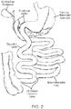
- the most common bariatric surgery is Roux-en-Y ( FIG. 1 ), in which a small gastric pouch and an alimentary limb (Roux limb) are created and anastomosed to one another and to the patient's jejunum, bypassing part of the small intestine.
- Other bariatric surgeries, as shown in FIG. 2 may involve removal of a portion of the stomach (sleeve gastrectomy or biliopancreatic diversion with duodenal switch).
- Leaks are one of the most dreaded complications after bariatric surgery and are associated with increased morbidity and mortality. Leaks can be treated with several modalities, including site drainage with parenteral nutrition and bowel rest, various endoscopic methods (esophageal stents, clips, glue, sutures), and a second bariatric surgery. These treatment modalities all have drawbacks.
- US 2009/0192588 A1 discloses a double stent for use in treatment of pulmonary diseases.
- the double stent includes a primary stent which may be a trumpet-shaped stent having expanded portions at its ends.
- a biodegradable stent is located on an outer circumference of the primary stent, is connected to the primary stent, and is outwardly curved.
- a thin film of polytetrafluoroethylene (PTFE) may be formed on an outer circumference of the primary stent.
- US 2003/0040804 A1 discloses a satiation device that may have an elongate tubular body.
- the tubular body has a proximal section and a distal section.
- the distal section has an hourglass profile including a pair of broadened sections and a waisted section therebetween.
- a polymeric barrier may be provided.
- the polymeric barrier may be a skin in which a mesh of the tubular body may be encapsulated.
- a stent for repairing post-anastomasis (e.g., bariatric) surgery leaks comprises an elongated tube having a proximal flare-shaped flange, an enlarged middle section, and a distal flare-shaped flange, wherein an exterior surface of the elongated tube is substantially covered with a polymer, such as an elastomeric polymer, to seal leaks and to prevent tissue in-growth.
- the elongated tube may be self expanding, and may be formed from an alloy or from a polymer.
- the stent may be of a woven type, and may further comprise a removal loop.
- the exterior surface of the elongated tube is coated with a drug.
- some or all of the stent and/or covering may be biodegradable.
- the polymer covering may swell in situ to aid in leakage prevention.
- a method of manufacturing a stent configured for repairing post-anastomasis (e.g., bariatric) surgery leaks comprises forming a stent having a middle bulge around a mandrel, and removing the mandrel from an interior of the stent.
- the mandrel comprises an expandable component (e.g., a balloon or a basket) configured to form the middle bulge, wherein removal of the mandrel comprises reducing the expandable component in order to remove it from the stent interior.
- the mandrel comprises a plurality of elements that may be disassembled and removed from the stent interior.
- the mandrel comprises a first coaxial section slidably disposed inside of a second coaxial section, wherein forming a stent having a middle bulge includes sliding the first and second coaxial sections away from each other to extend the mandrel, forming a stent around the extended mandrel, securing a first part of the stent to the first coaxial section, securing a second part of the stent to the second coaxial section, and sliding the first and second coaxial sections toward each other to create a middle bulge between the first and second parts of the stent.
- the step of removing the mandrel comprises destroying the mandrel.
- the formed stent may be covered by inserting the formed stent into an interior of a mold configured to mimic its exterior shape, adding covering solution to the interior of the mold, rotating and tilting the mold about a center axis to cover the formed stent with the covering solution, and removing the covered stent from the mold.
- Such processes for coating or covering the stent are referred to as sandwiching and electro-spinning.
- a method of repairing post-anastomasis (e.g., bariatric) surgery leaks in a patient includes mounting a shape memory polymer stent on an expandable device, such as an inflatable balloon or a mechanically expandable basket, inserting the expandable device having the stent mounted thereon into a body lumen of the patient proximate a site of a post-anastomasis surgery leak to be repaired, expanding the expandable device to thereby expand the stent against the leak, reducing the size of the expandable device while maintaining the expanded size of the stent, and removing the expandable device from the stent through the body lumen.
- Such surgical method may further include applying heat to soften and remove stent after the leaks have been allowed to heal.
- the disclosure is not limited to devices and methods of their manufacture and use for treatment of bariatric leaks, but are also applicable to the treatment of leaks resulting from any anastomosis surgery, i.e., between body lumens and/or between body lumens and organs, and in particular between body lumens and/or organs in the GI system.
- Embodiments of the disclosure may also be useful for treatment following full thickness resection procedures and/or urology procedures such as a radical prostatectomy.
- FIG. 3 illustrates a stent 10 configured to temporarily seal leaks after a Roux-en-Y bariatric surgery and to be removed after the leaks have healed.
- the stent 10 is designed to seal the locations where leaks are most likely to occur.
- the stent 10 is formed of an elongated tubular member 12 that is substantially covered with a polymer 14 to seal leaks and to prevent tissue in-growth, which would complicate removal after the leaks have healed.
- the tubular member 12 is shaped to prevent distal or proximal migration.
- the tubular member 12 has an enlarged middle segment 16 configured to sit in the gastric pouch and prevent distal or proximal migration. The middle segment 16 also prevents stagnation of food or liquid in the stomach by filling the gastric pouch.
- the middle segment 16 is an approximate sphere with a diameter of about 39 mm configured to fill a 30 ml gastric pouch.
- Proximal of the middle segment 16 is a proximal cylindrical segment 18 configured to extend from the distal esophagus into the proximal stomach, bridging the Z line.
- the proximal cylindrical segment 18 is about 20 mm in length and about 20 mm in cross-sectional diameter.
- Proximal of the proximal cylindrical segment 18 is a proximal flare-shaped flange 20 configured to expand along the wall of the distal esophagus to prevent any food or liquid from passing between the stent and the enteral wall.
- the proximal flange 20 is about 20 mm in length and about 30 mm in cross-sectional diameter at its widest point.
- Distal of the middle segment 16 is a distal cylindrical segment 22 configured to extend from the distal stomach into the jejunum, bridging the gastro-jejunal anastomosis and the Roux limb.
- the distal cylindrical segment 22 is about 20 to 70 mm in length and about 12 mm in cross-sectional diameter.
- distal of the distal cylindrical segment 22 is a distal flare-shaped flange 24 configured to expand along the wall of the jejunum to prevent any food or liquid from passing between the stent and the enteral wall.
- the distal flange 24 is about 20 mm in length and about 22 mm in cross-sectional diameter at its widest point.
- the tubular member 12 can be formed from alloys such as Elgiloy® and Nitinol® or polymers such as polyethylene terephthalate (PET), like a Polyflex® stent, and may also be made of a radiopaque material.
- the tubular member 12 is made of a biodegradable polymer and substantially covered with a biodegradable polymer 14, and is also radiopaque.
- the tubular member 12 can have a woven structure (i.e., constructed from one or more filaments). In one embodiment, the tubular member 12 is braided with one filament.
- the tubular member 12 is braided with several filaments, as is found, for example, in the WallFlex®, WALLSTENT® and Polyflex® stents made and distributed by Boston Scientific.
- the tubular member 12 is knitted, such as the UltraflexTM stents made by Boston Scientific.
- the tubular member 12 is of a knotted type, such the Precision ColonicTM stents made by Boston Scientific.
- the tubular member 12 is laser cut, such as the EPICTM stents made by Boston Scientific.
- the tubular member 12 can be a combination of any of the above-mentioned stent types.
- the stent 10 is self-expanding due to the combination of materials from which the stent 10 is made and the techniques used to make the stent.
- Fibers used to make the tubular member 12 may be cored fibers, e.g., having a NitinolTM outer shell and a platinum core. Reference is made to the stents disclosed in U.S. Patent Nos. 7,101,392 (Heath ), and 6,527,802 (Mayer ).
- the exterior surface of the tubular member 12 may be substantially covered with a polymer 14, which may be resistant to degradation.
- the polymer can be silicone, styrene isoprene butadiene (SIBS), expanded polytetrafluoroethylene (ePTFE or expanded Teflon®), or polyurethane.
- SIBS styrene isoprene butadiene
- ePTFE expanded polytetrafluoroethylene
- Teflon® expanded Teflon®
- polyurethane polyurethane.
- Substantially covering the tubular member 12 with polymer 14 improves the stents 10 ability to occlude leaks.
- the polymer 14 may be made of a material that swells and/or coated with an agent that swells in situ. The polymer 14 also reduces tissue in-growth, which facilitates removal after the leaks have healed, e.g., between 2 to 8 weeks after implantation.
- the stent 10 comprises a valve 11 to prevent reflux.
- the valve 11 is located in the proximal cylindrical segment 18 or distal cylindrical segment 22 and is configured to allow flow in the distal direction and prevent flow in the proximal direction.
- the stent 10 comprises a removal loop 13 to facilitate removing the stent 10 by pulling proximally.
- the stent 10 is coated with a drug configured to improve healing or, more generally, a therapeutic agent.
- the stent 10 includes radiopaque markers 15 for fluoroscopic positioning.
- the stent 10 in FIG. 4 is configured to temporarily seal leaks at the gastro-jejunal anastomosis after a Roux-en-Y bariatric surgery and to be removed after the leaks have healed.
- the distal cylindrical segment 22 and the distal flair-shaped flange 24 are identical to the corresponding parts in the stent 10 in FIG. 3 .
- Proximal of the distal cylindrical segment 22 is a gastric flange 26, configured to sit in the distal gastric pouch and prevent any food or liquid from passing between the stent and the enteral wall.
- the gastric flange 26 also cooperates with the distal flange 24 to prevent distal or proximal migration of the stent 10.
- the gastric flange 26 is a bowl with a length of about 20-30 mm and a diameter of about 40 mm at its widest point. This stent 10 is similar to distal half of the stent 10 in FIG. 3 .
- the flange 26 may take any open shape, such as, e.g., a bowl, a truncated cone, a saucer, etc.
- the stent 10 in FIG. 5 is configured to temporarily seal leaks after a sleeve gastrectomy or a biliopancreatic diversion with duodenal switch, and to be removed after the leaks have healed.
- the stomach pouch is long and thin, as shown in FIG. 2 .
- stents 10 used for sealing leaks after these procedures have a longer segment in the stomach.
- Such stents 10 are designed to seal the locations where leaks are most likely to occur after these procedures (i.e., Z line, stomach staple line, duodeno-jejunal anastomosis).
- the stent 10 may comprise an elongated tubular member 12 that is substantially covered with a polymer 14 as described above.
- the tubular member 12 is shaped to prevent distal or proximal migration.
- the tubular member 12 has an enlarged middle segment 16 configured to sit in the stomach antrum and prevent distal or proximal migration.
- the middle segment 16 has an ovoid shape with a length of about 60 mm and a cross-sectional diameter of about 50 mm at its widest point.
- the middle segment 16 is configured to sit in the antrum of the stomach and cooperates with the proximal and distal flanges 20, 24 to prevent distal or proximal migration of the stent 10.
- Proximal of the middle segment 16 is a proximal cylindrical segment 18 configured to extend from the distal esophagus into the proximal stomach, bridging the Z line.
- the proximal cylindrical segment 18 is about 260 mm in length and about 15 mm in cross-sectional diameter.
- Proximal of the proximal cylindrical segment 18 is a proximal flare-shaped flange 20 configured to expand along the wall of the distal esophagus to prevent any food or liquid from passing between the stent and the enteral wall.
- the proximal flange 20 is about 20 mm in length and about 30 mm in cross-sectional diameter at its widest point.
- a distal cylindrical segment 22 configured to extend from the distal stomach, through the duodenum and into the jejunum, bridging the duodeno-jejunal anastomosis.
- the distal cylindrical segment 22 is about 50 mm in length and about 20 mm in cross-sectional diameter.
- a distal flare-shaped flange 24 configured to expand along the wall of the jejunum to prevent any food or liquid from passing between the stent and the enteral wall.
- the distal flange 24 is about 20 mm in length and about 30 mm in cross-sectional diameter at its widest point. The same stent shape can also be used to treat leaks after sleeve gastrectomy.
- the dimensions of the above-described embodiments are provided for illustration and not limitation.
- One of skill in the art will recognize that the dimensions of the stent 10 can be modified to fit various anatomies.
- various mandrels 30 have been designed to facilitate removal of the mandrel 30 after forming the stent 10 around the mandrel 30.
- the mandrel 30 in FIGS. 6a and 6b has an inflatable component 32 in the middle of the mandrel 30. Either during or after forming the stent 10 around the mandrel 30, the inflatable component 32 is inflated to form the enlarged middle segment 16 of the stent 10.
- the inflatable component 32 is deflated and the mandrel 30 is removed from the stent 10 by disconnecting one of the enlarged flange forming end pieces from the mandrel 30.
- the mandrel 30 in FIG. 7 has wire elements 34 releasably attached to the middle of the mandrel 30 and configured to form the enlarged middle segment 16 of the stent 10.
- the wire elements 34 are released from the mandrel 30 and removed from the stent 10 along with the rest of the mandrel 30.
- the mandrel 30 in FIGS. 8a and 8b has a core 36 and two end pieces 38.
- the elements 34 are flat strips.
- the core 36 is configured to form the enlarged middle segment 16 of the stent 10.
- the elements may be configured to bow outwardly by axial movement of the mandrel towards the other end.
- the core 36 is disassembled as in FIG. 8b and removed from the stent 10 along with the end pieces 38.
- the core 36 may include six slices 40 that each has a projection 42 with two polar notches 44.
- Each of the end pieces 38 has a recess 46 into which one polar notch 44 from each slice 40 sits when the mandrel 30 is assembled to hold the core 36 together.
- the core 36 can be dissembled by pulling the end pieces 38 apart from each other.
- the slices 40 are cored out or hollowed to facilitate their removal from the stent 10. It will be appreciated that fewer or more end pieces 38 and/or slices 40 may be employed in alternate embodiments.
- the mandrel 30 in FIGS. 9a, 9b, and 9c is made of a first coaxial section 48 that is slidably disposed in a second coaxial section 50.
- first the coaxial sections 48, 50 are pulled apart from each other, as shown in FIG. 9a , such that the mandrel 30 is at its maximum length.
- the stent 10 is formed (but not set) around the elongated mandrel 30 and attached to the mandrel 30 at bonding points 54, as shown in FIG. 9b .
- the coaxial section 48, 50 are pushed toward 58 each other, as shown in FIG. 9c .
- This motion 58 along with the attachment of the stent 10 to the mandrel 30 causes the middle of the mandrel 30 to displace radially and form the enlarged middle segment 16 of the stent 10. Then the stent 10 is set and the mandrel 30 is removed from the stent 10. In other embodiments, the mandrel 30 is removed from the stent 10 by destroying the mandrel 30.
- the stent 10 can be substantially covered with polymer 14 through various methods (e.g., dipping, spraying, sandwiching, heat shrinking or electro-spinning).
- the stent 10 is inserted 62 into an interior of a mold configured to mimic the exterior shape of the stent 10.
- a covering solution is added 64 to the interior of the mold.
- mold is rotated and tilted 66 about its center axis to cover the stent 10 with the covering solution.
- the covered stent 10 is removed 68 from the mold. Heat can be added to the process for solvent evaporation and/or curing.
- the formed and covered stent 10 can be implanted during an endoscopic procedure. During the procedure, the stent 10 is mounted on a delivery device for delivery under direction vision or under fluoroscopy. In the embodiment shown in FIG. 11 , a stent 10 made from a shape memory polymer is delivered over an inflatable balloon or a mechanically expandable basket that is expanded in-situ to impart the desired shape to the stent 10.
- Shape memory polymers generally have both hard and soft molecular structures, which are relative terms relating to the transition temperature of the segments. These "segments" are blocks or sequences of polymer forming part of the shape memory polymer. Typically, hard segments have a higher glass transition temperature (Tg) than soft segments. Shape memory polymers include a class of (meth)acrylate compositions having a first (meth)acrylate monomer with a lower glass transition temperature (Tg typically less than 25°C) and a second (meth)acrylate monomer with a higher glass transition temperature (Tg typically greater than 25°C).
- Shape memory polymers e.g., thermoplastic and thermoset (covalently cross-linked) polymeric materials, used for forming stents 10 may include elastomers that are typically crosslinked and/or crystalline and exhibit melt or glass transitions at temperatures that are above body temperature and safe for use in the body (e.g., at about 40 °C to about 50 °C).
- Such shape memory polymers include those that maintain stent geometry under expansion conditions without fracture or substantial irreversible stress relaxation or creep.
- the stent 10 may be heated to or above the melt or glass transition temperature of the shape memory polymer during expansion. In these temperatures, the polymer may be in a softened state.
- the shape memory polymer After the stent 10 is fully expanded and cooled, the shape memory polymer substantially sets in the desired shape and location (e.g., adjacent a leak site).
- the polymer can have some elastomeric properties in the cooled, hardened state so that the stent 10 can flex with natural body motion. After cooling, the stent 10 exhibits sufficient resistance to inward radial force to keep a body lumen open. After the leaks have healed, the stent 10 may be softened by heating for removal.
- a leak is repaired by first mounting 70 a shape memory polymer stent 10 on an expandable device, such as (without limitation) an inflatable balloon or a mechanically expandable basket.
- an expandable device such as (without limitation) an inflatable balloon or a mechanically expandable basket.
- the expandable device and stent 10 are then inserted 72 into the alimentary canal proximate a leak.
- the expandable device is then expanded, thereby expanding the stent 10 against the leak.
- the expandable device is a balloon that is expanded 74 by application of pressure, and heat is added to thereby soften the stent to allow for its in-situ expansion.
- the stent 10 is allowed to cool and set 76, while the expanded size of the balloon is maintained in order to form the desired shape of the stent 10.
- the balloon is deflated 78 by removing the application of pressure, and the balloon is removed 80 from the stent through the alimentary canal.
- the stent may (optionally) be removed by softening the stent with the application of heat 84.
Description
- The disclosed invention pertains to stents configured for repairing post-anastomasis (e.g., bariatric) surgery leaks.
- Obesity is a medical condition in which excess body fat has accumulated to the extent that it may have an adverse effect on health, leading to reduced life expectancy and/or increased health problems. Body mass index (BMI), a measurement which compares weight and height, defines people as overweight (pre-obese) when their BMI is between 25 kg/m2 and 30 kg/m2, and obese when it is greater than 30 kg/m2. Obesity is most commonly caused by a combination of excessive dietary calories, lack of physical activity, and genetic susceptibility. On average, obesity reduces life expectancy by six to seven years. Obesity increases the likelihood of various diseases, particularly heart disease,
type 2 diabetes, breathing difficulties during sleep, certain types of cancer, and osteoarthritis. Obesity is a leading preventable cause of death worldwide, with increasing prevalence in adults and children, and authorities view it as one of the most serious public health problems of the 21st century. The WHO estimated in 2005 that at least 400 million adults (9.8%) worldwide were obese. According to a CDC report, 34% of adults and 17% of children in the United States were obese in 2007-2008. Obesity has been estimated to cause up to 365,000 deaths per year in the United States. - Bariatric (or weight loss) surgeries are surgical treatments for treating severe obesity (BMI greater than 40 kg/m2). The most common bariatric surgery is Roux-en-Y (
FIG. 1 ), in which a small gastric pouch and an alimentary limb (Roux limb) are created and anastomosed to one another and to the patient's jejunum, bypassing part of the small intestine. Other bariatric surgeries, as shown inFIG. 2 , may involve removal of a portion of the stomach (sleeve gastrectomy or biliopancreatic diversion with duodenal switch). In biliopancreatic diversion with duodenal switch, about 80 percent of the stomach is removed, forming a thin sleeve-like stomach. The valve that releases food to the small intestine remains (pylorus) along with a limited portion of the small intestine that normally connects to the stomach (duodenum). The surgery bypasses the majority of the intestine by connecting the end portion of the intestine to the duodenum near the stomach (biliopancreatic diversion). This weight-loss surgery is effective but has more risks, such as malnutrition and vitamin deficiencies, and requires close monitoring. It is generally used for people who have a body mass index greater than 50 kg/m2. About 150,000 patients undergo bariatric surgery each year. Long-term studies show the procedures cause significant long-term loss of weight, recovery from diabetes, improvement in cardiovascular risk factors, and a reduction in mortality of 23% to 40%. - It is reported that post operative leaks occur in about 2% to 3% of bariatric surgery cases, but the real number may be higher due to underreporting. Leaks mostly occur along the stapling line of the gastric pouch and at the gastrojejunal anastomosis. However, leaks can also occur along the Z line between the esophagus and the stomach. Leaks are one of the most dreaded complications after bariatric surgery and are associated with increased morbidity and mortality. Leaks can be treated with several modalities, including site drainage with parenteral nutrition and bowel rest, various endoscopic methods (esophageal stents, clips, glue, sutures), and a second bariatric surgery. These treatment modalities all have drawbacks.
US 2009/0192588 A1 discloses a double stent for use in treatment of pulmonary diseases. The double stent includes a primary stent which may be a trumpet-shaped stent having expanded portions at its ends. A biodegradable stent is located on an outer circumference of the primary stent, is connected to the primary stent, and is outwardly curved. A thin film of polytetrafluoroethylene (PTFE) may be formed on an outer circumference of the primary stent.
US 2003/0040804 A1 discloses a satiation device that may have an elongate tubular body. The tubular body has a proximal section and a distal section. The distal section has an hourglass profile including a pair of broadened sections and a waisted section therebetween. A polymeric barrier may be provided. The polymeric barrier may be a skin in which a mesh of the tubular body may be encapsulated. - The present invention is defined by the features of the claims. In one embodiment of the disclosed invention, a stent for repairing post-anastomasis (e.g., bariatric) surgery leaks comprises an elongated tube having a proximal flare-shaped flange, an enlarged middle section, and a distal flare-shaped flange, wherein an exterior surface of the elongated tube is substantially covered with a polymer, such as an elastomeric polymer, to seal leaks and to prevent tissue in-growth. The elongated tube may be self expanding, and may be formed from an alloy or from a polymer. The stent may be of a woven type, and may further comprise a removal loop. Optionally, the exterior surface of the elongated tube is coated with a drug. Optionally, some or all of the stent and/or covering may be biodegradable. The polymer covering may swell in situ to aid in leakage prevention.
- In another embodiment not forming part of the present invention, a method of manufacturing a stent configured for repairing post-anastomasis (e.g., bariatric) surgery leaks comprises forming a stent having a middle bulge around a mandrel, and removing the mandrel from an interior of the stent.
- In some embodiments, the mandrel comprises an expandable component (e.g., a balloon or a basket) configured to form the middle bulge, wherein removal of the mandrel comprises reducing the expandable component in order to remove it from the stent interior. In one embodiment, the mandrel comprises a plurality of elements that may be disassembled and removed from the stent interior.
- In another embodiment, the mandrel comprises a first coaxial section slidably disposed inside of a second coaxial section, wherein forming a stent having a middle bulge includes sliding the first and second coaxial sections away from each other to extend the mandrel, forming a stent around the extended mandrel, securing a first part of the stent to the first coaxial section, securing a second part of the stent to the second coaxial section, and sliding the first and second coaxial sections toward each other to create a middle bulge between the first and second parts of the stent.
- In yet another embodiment, the step of removing the mandrel comprises destroying the mandrel.
- The formed stent may be covered by inserting the formed stent into an interior of a mold configured to mimic its exterior shape, adding covering solution to the interior of the mold, rotating and tilting the mold about a center axis to cover the formed stent with the covering solution, and removing the covered stent from the mold. Such processes for coating or covering the stent are referred to as sandwiching and electro-spinning.
- In still another embodiment not forming part of the present invention, a method of repairing post-anastomasis (e.g., bariatric) surgery leaks in a patient includes mounting a shape memory polymer stent on an expandable device, such as an inflatable balloon or a mechanically expandable basket, inserting the expandable device having the stent mounted thereon into a body lumen of the patient proximate a site of a post-anastomasis surgery leak to be repaired, expanding the expandable device to thereby expand the stent against the leak, reducing the size of the expandable device while maintaining the expanded size of the stent, and removing the expandable device from the stent through the body lumen. Such surgical method may further include applying heat to soften and remove stent after the leaks have been allowed to heal.
- Other and further aspects and features of embodiments of the disclosed invention will become apparent from the ensuing detailed description in view of the accompanying figures.
- Referring now to the drawings, in which like reference numbers represent corresponding parts throughout:
-
FIG. 1 is a schematic view of portions of an alimentary canal after a Roux-en-Y procedure. -
FIG. 2 is a schematic view of portions of an alimentary canal after a biliopancreatic diversion with duodenal switch procedure. -
FIG. 3 is a longitudinal cross-section view of a stent constructed according to one embodiment of the disclosed invention. -
FIG. 4 is a longitudinal cross-section view of a stent constructed according to another embodiment not forming part of the invention. -
FIG. 5 is a longitudinal cross-section view of a stent constructed according to yet another embodiment not forming part of the present invention. -
FIGS. 6a and 6b are respective deflated and inflated longitudinal cross-section views of a mandrel according to one embodiment not forming part of the present invention. -
FIG. 7 is a perspective view of a mandrel according to yet another embodiment not forming part of the present invention. -
FIGS. 8a and8b are respective assembled and disassembled perspective views of a mandrel not forming part of the present invention. -
FIGS. 9a, 9b and 9c are respective perspective views of a mandrel according to still another embodiment not forming part of the present invention. - In
FIGS. 9a and 9b , the mandrel is fully extended. InFIG. 9c , the mandrel is shortened. -
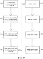
FIG. 10 is a flow chart of a process for covering a stent, according to still another embodiment not forming part of the present invention. -
FIG. 11 is a flow chart of a method of repairing post-anastomasis surgery leaks using a shape memory polymer stent according to still another embodiment not forming part of the present invention. - The following Detailed Description of the Illustrated Embodiments, and of alternate embodiments not shown, is provided for purposes of explaining the inventive concepts disclosed herein, and not for purposes of limitation of the appended claims. In particular, while the Detailed Description of the Illustrated Embodiments is directed to the repair of post-bariatric surgery leaks, in a broader aspect, the the disclosure is not limited to devices and methods of their manufacture and use for treatment of bariatric leaks, but are also applicable to the treatment of leaks resulting from any anastomosis surgery, i.e., between body lumens and/or between body lumens and organs, and in particular between body lumens and/or organs in the GI system. Embodiments of the disclosure may also be useful for treatment following full thickness resection procedures and/or urology procedures such as a radical prostatectomy.
-
FIG. 3 illustrates astent 10 configured to temporarily seal leaks after a Roux-en-Y bariatric surgery and to be removed after the leaks have healed. Thestent 10 is designed to seal the locations where leaks are most likely to occur. Thestent 10 is formed of anelongated tubular member 12 that is substantially covered with apolymer 14 to seal leaks and to prevent tissue in-growth, which would complicate removal after the leaks have healed. Thetubular member 12 is shaped to prevent distal or proximal migration. Thetubular member 12 has an enlargedmiddle segment 16 configured to sit in the gastric pouch and prevent distal or proximal migration. Themiddle segment 16 also prevents stagnation of food or liquid in the stomach by filling the gastric pouch. In one embodiment, themiddle segment 16 is an approximate sphere with a diameter of about 39 mm configured to fill a 30 ml gastric pouch. Proximal of themiddle segment 16 is a proximalcylindrical segment 18 configured to extend from the distal esophagus into the proximal stomach, bridging the Z line. In one embodiment, the proximalcylindrical segment 18 is about 20 mm in length and about 20 mm in cross-sectional diameter. - Proximal of the proximal
cylindrical segment 18 is a proximal flare-shapedflange 20 configured to expand along the wall of the distal esophagus to prevent any food or liquid from passing between the stent and the enteral wall. In one embodiment, theproximal flange 20 is about 20 mm in length and about 30 mm in cross-sectional diameter at its widest point. Distal of themiddle segment 16 is a distalcylindrical segment 22 configured to extend from the distal stomach into the jejunum, bridging the gastro-jejunal anastomosis and the Roux limb. In one embodiment, the distalcylindrical segment 22 is about 20 to 70 mm in length and about 12 mm in cross-sectional diameter. Distal of the distalcylindrical segment 22 is a distal flare-shapedflange 24 configured to expand along the wall of the jejunum to prevent any food or liquid from passing between the stent and the enteral wall. In one embodiment, thedistal flange 24 is about 20 mm in length and about 22 mm in cross-sectional diameter at its widest point. - The
tubular member 12 can be formed from alloys such as Elgiloy® and Nitinol® or polymers such as polyethylene terephthalate (PET), like a Polyflex® stent, and may also be made of a radiopaque material. In some embodiments, thetubular member 12 is made of a biodegradable polymer and substantially covered with abiodegradable polymer 14, and is also radiopaque. Thetubular member 12 can have a woven structure (i.e., constructed from one or more filaments). In one embodiment, thetubular member 12 is braided with one filament. In other embodiments, thetubular member 12 is braided with several filaments, as is found, for example, in the WallFlex®, WALLSTENT® and Polyflex® stents made and distributed by Boston Scientific. In still another embodiment, thetubular member 12 is knitted, such as the Ultraflex™ stents made by Boston Scientific. In yet another embodiment, thetubular member 12 is of a knotted type, such the Precision Colonic™ stents made by Boston Scientific. In still another embodiment, thetubular member 12 is laser cut, such as the EPIC™ stents made by Boston Scientific. Alternatively, thetubular member 12 can be a combination of any of the above-mentioned stent types. In some embodiments, thestent 10 is self-expanding due to the combination of materials from which thestent 10 is made and the techniques used to make the stent. Fibers used to make thetubular member 12 may be cored fibers, e.g., having a Nitinol™ outer shell and a platinum core. Reference is made to the stents disclosed inU.S. Patent Nos. 7,101,392 (Heath ), and6,527,802 (Mayer ). - The exterior surface of the
tubular member 12 may be substantially covered with apolymer 14, which may be resistant to degradation. In various embodiments, the polymer can be silicone, styrene isoprene butadiene (SIBS), expanded polytetrafluoroethylene (ePTFE or expanded Teflon®), or polyurethane. Substantially covering thetubular member 12 withpolymer 14 improves thestents 10 ability to occlude leaks. In this regard, thepolymer 14 may be made of a material that swells and/or coated with an agent that swells in situ. Thepolymer 14 also reduces tissue in-growth, which facilitates removal after the leaks have healed, e.g., between 2 to 8 weeks after implantation. - In some embodiments, the
stent 10 comprises avalve 11 to prevent reflux. Thevalve 11 is located in the proximalcylindrical segment 18 or distalcylindrical segment 22 and is configured to allow flow in the distal direction and prevent flow in the proximal direction. In other embodiments, thestent 10 comprises aremoval loop 13 to facilitate removing thestent 10 by pulling proximally. In still other embodiments, thestent 10 is coated with a drug configured to improve healing or, more generally, a therapeutic agent. In yet other embodiments, thestent 10 includesradiopaque markers 15 for fluoroscopic positioning. - The
stent 10 inFIG. 4 is configured to temporarily seal leaks at the gastro-jejunal anastomosis after a Roux-en-Y bariatric surgery and to be removed after the leaks have healed. The distalcylindrical segment 22 and the distal flair-shapedflange 24 are identical to the corresponding parts in thestent 10 inFIG. 3 . Proximal of the distalcylindrical segment 22 is a gastric flange 26, configured to sit in the distal gastric pouch and prevent any food or liquid from passing between the stent and the enteral wall. The gastric flange 26 also cooperates with thedistal flange 24 to prevent distal or proximal migration of thestent 10. In one embodiment, the gastric flange 26 is a bowl with a length of about 20-30 mm and a diameter of about 40 mm at its widest point. Thisstent 10 is similar to distal half of thestent 10 inFIG. 3 . In alternative embodiments, the flange 26 may take any open shape, such as, e.g., a bowl, a truncated cone, a saucer, etc. - The
stent 10 inFIG. 5 is configured to temporarily seal leaks after a sleeve gastrectomy or a biliopancreatic diversion with duodenal switch, and to be removed after the leaks have healed. After these procedures, the stomach pouch is long and thin, as shown inFIG. 2 . Accordingly,stents 10 used for sealing leaks after these procedures have a longer segment in the stomach.Such stents 10 are designed to seal the locations where leaks are most likely to occur after these procedures (i.e., Z line, stomach staple line, duodeno-jejunal anastomosis). Thestent 10 may comprise anelongated tubular member 12 that is substantially covered with apolymer 14 as described above. Thetubular member 12 is shaped to prevent distal or proximal migration. - The
tubular member 12 has an enlargedmiddle segment 16 configured to sit in the stomach antrum and prevent distal or proximal migration. In one embodiment, themiddle segment 16 has an ovoid shape with a length of about 60 mm and a cross-sectional diameter of about 50 mm at its widest point. Themiddle segment 16 is configured to sit in the antrum of the stomach and cooperates with the proximal anddistal flanges stent 10. - Proximal of the
middle segment 16 is a proximalcylindrical segment 18 configured to extend from the distal esophagus into the proximal stomach, bridging the Z line. In one embodiment, the proximalcylindrical segment 18 is about 260 mm in length and about 15 mm in cross-sectional diameter. Proximal of the proximalcylindrical segment 18 is a proximal flare-shapedflange 20 configured to expand along the wall of the distal esophagus to prevent any food or liquid from passing between the stent and the enteral wall. In one embodiment, theproximal flange 20 is about 20 mm in length and about 30 mm in cross-sectional diameter at its widest point. Distal of themiddle segment 16 is a distalcylindrical segment 22 configured to extend from the distal stomach, through the duodenum and into the jejunum, bridging the duodeno-jejunal anastomosis. In one embodiment, the distalcylindrical segment 22 is about 50 mm in length and about 20 mm in cross-sectional diameter. Distal of the distalcylindrical segment 22 is a distal flare-shapedflange 24 configured to expand along the wall of the jejunum to prevent any food or liquid from passing between the stent and the enteral wall. In one embodiment, thedistal flange 24 is about 20 mm in length and about 30 mm in cross-sectional diameter at its widest point. The same stent shape can also be used to treat leaks after sleeve gastrectomy. - The dimensions of the above-described embodiments are provided for illustration and not limitation. One of skill in the art will recognize that the dimensions of the
stent 10 can be modified to fit various anatomies. Because some embodiments of thestent 10 include an enlargedmiddle segment 16,various mandrels 30 have been designed to facilitate removal of themandrel 30 after forming thestent 10 around themandrel 30. Themandrel 30 inFIGS. 6a and 6b has aninflatable component 32 in the middle of themandrel 30. Either during or after forming thestent 10 around themandrel 30, theinflatable component 32 is inflated to form the enlargedmiddle segment 16 of thestent 10. After thestent 10 is formed, e.g., braided and heat-treated, theinflatable component 32 is deflated and themandrel 30 is removed from thestent 10 by disconnecting one of the enlarged flange forming end pieces from themandrel 30. - The
mandrel 30 inFIG. 7 haswire elements 34 releasably attached to the middle of themandrel 30 and configured to form the enlargedmiddle segment 16 of thestent 10. After thestent 10 is formed around themandrel 30, thewire elements 34 are released from themandrel 30 and removed from thestent 10 along with the rest of themandrel 30. Themandrel 30 inFIGS. 8a and8b has acore 36 and twoend pieces 38. In some embodiments, theelements 34 are flat strips. When themandrel 30 is assembled (FIG. 8a ), thecore 36 is configured to form the enlargedmiddle segment 16 of thestent 10. For example, the elements may be configured to bow outwardly by axial movement of the mandrel towards the other end. - After the
stent 10 is formed around themandrel 30, thecore 36 is disassembled as inFIG. 8b and removed from thestent 10 along with theend pieces 38. As shown inFIG. 8b , thecore 36 may include sixslices 40 that each has aprojection 42 with twopolar notches 44. Each of theend pieces 38 has arecess 46 into which onepolar notch 44 from eachslice 40 sits when themandrel 30 is assembled to hold the core 36 together. Accordingly, the core 36 can be dissembled by pulling theend pieces 38 apart from each other. In some embodiments, theslices 40 are cored out or hollowed to facilitate their removal from thestent 10. It will be appreciated that fewer ormore end pieces 38 and/orslices 40 may be employed in alternate embodiments. - The
mandrel 30 inFIGS. 9a, 9b, and 9c is made of a firstcoaxial section 48 that is slidably disposed in a secondcoaxial section 50. First thecoaxial sections FIG. 9a , such that themandrel 30 is at its maximum length. Then thestent 10 is formed (but not set) around theelongated mandrel 30 and attached to themandrel 30 at bonding points 54, as shown inFIG. 9b . Next thecoaxial section FIG. 9c . Thismotion 58 along with the attachment of thestent 10 to themandrel 30 causes the middle of themandrel 30 to displace radially and form the enlargedmiddle segment 16 of thestent 10. Then thestent 10 is set and themandrel 30 is removed from thestent 10. In other embodiments, themandrel 30 is removed from thestent 10 by destroying themandrel 30. - After the
stent 10 is formed and themandrel 30 is removed, thestent 10 can be substantially covered withpolymer 14 through various methods (e.g., dipping, spraying, sandwiching, heat shrinking or electro-spinning). In the embodiment shown inFIG. 10 , thestent 10 is inserted 62 into an interior of a mold configured to mimic the exterior shape of thestent 10. Then a covering solution is added 64 to the interior of the mold. Next, mold is rotated and tilted 66 about its center axis to cover thestent 10 with the covering solution. Finally, the coveredstent 10 is removed 68 from the mold. Heat can be added to the process for solvent evaporation and/or curing. The formed and coveredstent 10 can be implanted during an endoscopic procedure. During the procedure, thestent 10 is mounted on a delivery device for delivery under direction vision or under fluoroscopy. In the embodiment shown inFIG. 11 , astent 10 made from a shape memory polymer is delivered over an inflatable balloon or a mechanically expandable basket that is expanded in-situ to impart the desired shape to thestent 10. - Shape memory polymers generally have both hard and soft molecular structures, which are relative terms relating to the transition temperature of the segments. These "segments" are blocks or sequences of polymer forming part of the shape memory polymer. Typically, hard segments have a higher glass transition temperature (Tg) than soft segments. Shape memory polymers include a class of (meth)acrylate compositions having a first (meth)acrylate monomer with a lower glass transition temperature (Tg typically less than 25°C) and a second (meth)acrylate monomer with a higher glass transition temperature (Tg typically greater than 25°C).
- Shape memory polymers, e.g., thermoplastic and thermoset (covalently cross-linked) polymeric materials, used for forming
stents 10 may include elastomers that are typically crosslinked and/or crystalline and exhibit melt or glass transitions at temperatures that are above body temperature and safe for use in the body (e.g., at about 40 °C to about 50 °C). Such shape memory polymers include those that maintain stent geometry under expansion conditions without fracture or substantial irreversible stress relaxation or creep. Typically, thestent 10 may be heated to or above the melt or glass transition temperature of the shape memory polymer during expansion. In these temperatures, the polymer may be in a softened state. After thestent 10 is fully expanded and cooled, the shape memory polymer substantially sets in the desired shape and location (e.g., adjacent a leak site). The polymer can have some elastomeric properties in the cooled, hardened state so that thestent 10 can flex with natural body motion. After cooling, thestent 10 exhibits sufficient resistance to inward radial force to keep a body lumen open. After the leaks have healed, thestent 10 may be softened by heating for removal. - Referring to
FIG. 11 , a leak is repaired by first mounting 70 a shapememory polymer stent 10 on an expandable device, such as (without limitation) an inflatable balloon or a mechanically expandable basket. The expandable device andstent 10 are then inserted 72 into the alimentary canal proximate a leak. Next, the expandable device is then expanded, thereby expanding thestent 10 against the leak. In the embodiment ofFIG. 11 , the expandable device is a balloon that is expanded 74 by application of pressure, and heat is added to thereby soften the stent to allow for its in-situ expansion. The application of added heat is stopped, and thestent 10 is allowed to cool and set 76, while the expanded size of the balloon is maintained in order to form the desired shape of thestent 10. Next, the balloon is deflated 78 by removing the application of pressure, and the balloon is removed 80 from the stent through the alimentary canal. After the leaks have healed 82, the stent may (optionally) be removed by softening the stent with the application ofheat 84. - While various embodiments of the disclosed inventions have been shown and described, it should be appreciated that they are presented for purposes of illustration, and not limitation. It will be appreciated that various modifications may be made to the illustrated and described embodiments without departing from the scope of the disclosed invention, which is to be defined only by the following claims and their equivalents.
Claims (10)
- A stent (10) for repairing post-anastomosis surgery leaks, comprising:
an elongated tube (12) having a proximal flare-shaped flange (20), a proximal cylindrical segment (18) located distal to the proximal flare-shaped flange (20), an enlarged middle section (16), a distal cylindrical segment (22), and a distal flare-shaped flange (24) located distal to the distal cylindrical segment (22), wherein an exterior surface of the elongated tube (12) is substantially covered with a polymer (14) to seal leaks and to prevent tissue in-growth, and wherein the enlarged middle section (16) is integrally formed with the elongated tube (12). - The stent of claim 1, wherein the elongated tube (12) is self expanding.
- The stent of claim 1, wherein the elongated tube (12) is formed from an alloy and/or a polymer.
- The stent of claim 1, wherein the elongated tube (12) is radiopaque and/or comprises a radiopaque marker.
- The stent of claim 1, wherein the elongated tube (12) is woven, braided, or knitted.
- The stent of claim 1, wherein the elongated tube (12) is laser cut.
- The stent of claim 1, the elongated tube (12) further comprising a valve (11) configured to prevent reflux through the stent (10).
- The stent of claim 1, further comprising a removal loop (13).
- The stent of claim 1, wherein the exterior surface of the elongated tube (12) is coated with a therapeutic agent.
- The stent of claim 1, wherein the elongated tube (12) is formed from and/or substantially covered by biodegradable polymer.
Applications Claiming Priority (2)
| Application Number | Priority Date | Filing Date | Title |
|---|---|---|---|
| US32989310P | 2010-04-30 | 2010-04-30 | |
| PCT/US2011/034511 WO2011137318A2 (en) | 2010-04-30 | 2011-04-29 | Stent for repair of anastomasis surgery leaks |
Publications (2)
| Publication Number | Publication Date |
|---|---|
| EP2563295A2 EP2563295A2 (en) | 2013-03-06 |
| EP2563295B1 true EP2563295B1 (en) | 2020-07-01 |
Family
ID=44280652
Family Applications (1)
| Application Number | Title | Priority Date | Filing Date |
|---|---|---|---|
| EP11718868.0A Active EP2563295B1 (en) | 2010-04-30 | 2011-04-29 | Stent for repair of anastomasis surgery leaks |
Country Status (3)
| Country | Link |
|---|---|
| US (3) | US10398540B2 (en) |
| EP (1) | EP2563295B1 (en) |
| WO (1) | WO2011137318A2 (en) |
Families Citing this family (26)
| Publication number | Priority date | Publication date | Assignee | Title |
|---|---|---|---|---|
| US8685082B2 (en) * | 2010-11-18 | 2014-04-01 | National Cerebral And Cardiovascular Center | Base material for forming valved lumen shape tissue, method for producing valved lumen shape tissue, and valved artificial blood vessel |
| RU2626885C2 (en) * | 2011-12-19 | 2017-08-02 | Колопласт А/С | Endoluminal prosthesis and gastrointestinal implant |
| US9433991B2 (en) | 2011-12-21 | 2016-09-06 | Edwards Lifesciences Corporation | Apparatus and method for stent shaping |
| WO2013192208A1 (en) * | 2012-06-18 | 2013-12-27 | Board Of Regents Of The University Of Nebraska | Stent to assist in arteriovenous fistula formation |
| CN102783976B (en) * | 2012-08-21 | 2014-12-10 | 万平 | Internal tectorial membrane made by electrospinning for duodenum |
| EP2961349A1 (en) | 2013-02-28 | 2016-01-06 | Boston Scientific Scimed, Inc. | Stent with balloon for repair of anastomosis surgery leaks |
| JP6311066B2 (en) | 2014-05-28 | 2018-04-11 | ボストン サイエンティフィック サイムド,インコーポレイテッドBoston Scientific Scimed,Inc. | Stent delivery system |
| US9579186B2 (en) * | 2014-06-26 | 2017-02-28 | Boston Scientific Scimed, Inc. | Medical devices and methods to prevent bile reflux after bariatric procedures |
| US9801749B2 (en) | 2014-09-18 | 2017-10-31 | Boston Scientific Scimed, Inc. | Methods allowing pyloric sphincter to normally function for bariatric stents |
| EP3265025B1 (en) | 2015-03-05 | 2022-04-13 | Merit Medical Systems, Inc. | Vascular prosthesis deployment device |
| US10470906B2 (en) | 2015-09-15 | 2019-11-12 | Merit Medical Systems, Inc. | Implantable device delivery system |
| US10456237B2 (en) | 2016-03-07 | 2019-10-29 | Boston Scientific Scimed, Inc. | Esophageal stent including a valve member |
| US11129739B2 (en) | 2016-06-03 | 2021-09-28 | Boston Scientific Scimed, Inc. | Gastrointestinal bypass devices and related methods of use |
| CN115054413A (en) | 2016-09-29 | 2022-09-16 | 美国医疗设备有限公司 | Method of adjusting effective length of stent and prosthesis delivery catheter assembly |
| US11135050B2 (en) | 2016-10-04 | 2021-10-05 | Boston Scientific Scimed, Inc. | Stent including anchoring members |
| US10744009B2 (en) | 2017-03-15 | 2020-08-18 | Merit Medical Systems, Inc. | Transluminal stents and related methods |
| US11628078B2 (en) | 2017-03-15 | 2023-04-18 | Merit Medical Systems, Inc. | Transluminal delivery devices and related kits and methods |
| USD836194S1 (en) | 2017-03-21 | 2018-12-18 | Merit Medical Systems, Inc. | Stent deployment device |
| US11896506B2 (en) | 2017-07-27 | 2024-02-13 | Boston Scientific Scimed, Inc. | Adjustable mandrel for forming stent with anti-migration features |
| WO2019209745A1 (en) | 2018-04-23 | 2019-10-31 | Boston Scientific Scimed, Inc. | Stent with selectively covered region |
| KR20230152842A (en) | 2018-06-04 | 2023-11-03 | 보스톤 싸이엔티픽 싸이메드 인코포레이티드 | Removable stent |
| US11399970B2 (en) | 2018-09-24 | 2022-08-02 | Boston Scientific Scimed, Inc. | Repositionable and removable stents |
| CN114126548A (en) * | 2019-07-17 | 2022-03-01 | 波士顿科学国际有限公司 | Stents, systems and methods for gastrointestinal tract treatment |
| US11730614B2 (en) | 2019-10-15 | 2023-08-22 | Boston Scientific Scimed, Inc. | System, device and method for anchoring a stent |
| WO2021158564A1 (en) | 2020-02-03 | 2021-08-12 | Boston Scientific Scimed, Inc. | Stent, mandrel, and method for forming a stent with anti-migration features |
| EP4255356A1 (en) | 2020-12-02 | 2023-10-11 | Boston Scientific Scimed, Inc. | Stent with improved deployment characteristics |
Family Cites Families (29)
| Publication number | Priority date | Publication date | Assignee | Title |
|---|---|---|---|---|
| US7101392B2 (en) | 1992-03-31 | 2006-09-05 | Boston Scientific Corporation | Tubular medical endoprostheses |
| US5630840A (en) | 1993-01-19 | 1997-05-20 | Schneider (Usa) Inc | Clad composite stent |
| CA2194671A1 (en) * | 1994-07-08 | 1996-01-25 | Ev3 Inc. | Method of forming medical devices; intravascular occlusion devices |
| US6193745B1 (en) * | 1995-10-03 | 2001-02-27 | Medtronic, Inc. | Modular intraluminal prosteheses construction and methods |
| US6156064A (en) * | 1998-08-14 | 2000-12-05 | Schneider (Usa) Inc | Stent-graft-membrane and method of making the same |
| US6340368B1 (en) * | 1998-10-23 | 2002-01-22 | Medtronic Inc. | Implantable device with radiopaque ends |
| US6299637B1 (en) * | 1999-08-20 | 2001-10-09 | Samuel M. Shaolian | Transluminally implantable venous valve |
| US6613082B2 (en) * | 2000-03-13 | 2003-09-02 | Jun Yang | Stent having cover with drug delivery capability |
| US8038708B2 (en) * | 2001-02-05 | 2011-10-18 | Cook Medical Technologies Llc | Implantable device with remodelable material and covering material |
| US6562066B1 (en) * | 2001-03-02 | 2003-05-13 | Eric C. Martin | Stent for arterialization of the coronary sinus and retrograde perfusion of the myocardium |
| US6675809B2 (en) * | 2001-08-27 | 2004-01-13 | Richard S. Stack | Satiation devices and methods |
| US7037329B2 (en) * | 2002-01-07 | 2006-05-02 | Eric C. Martin | Bifurcated stent for percutaneous arterialization of the coronary sinus and retrograde perfusion of the myocardium |
| US7288111B1 (en) * | 2002-03-26 | 2007-10-30 | Thoratec Corporation | Flexible stent and method of making the same |
| FR2847155B1 (en) * | 2002-11-20 | 2005-08-05 | Younes Boudjemline | METHOD FOR MANUFACTURING A MEDICAL IMPLANT WITH ADJUSTED STRUCTURE AND IMPLANT OBTAINED THEREBY |
| US7717952B2 (en) * | 2003-04-24 | 2010-05-18 | Cook Incorporated | Artificial prostheses with preferred geometries |
| DE10351220A1 (en) * | 2003-10-28 | 2005-06-02 | Deutsche Institute für Textil- und Faserforschung Stuttgart - Stiftung des öffentlichen Rechts | Tubular implant |
| US8747453B2 (en) * | 2008-02-18 | 2014-06-10 | Aga Medical Corporation | Stent/stent graft for reinforcement of vascular abnormalities and associated method |
| MXPA06010495A (en) * | 2004-03-19 | 2006-12-19 | Pvaxx Res & Dev Ltd | Load-carrying apparatus and methods of manufacture. |
| EP1850791B1 (en) * | 2005-01-28 | 2017-08-16 | Boston Scientific Limited | Stent retrieval member and devices for retrieving or repositioning a stent |
| US20060271161A1 (en) * | 2005-05-26 | 2006-11-30 | Boston Scientific Scimed, Inc. | Selective treatment of stent side branch petals |
| ATE525986T1 (en) * | 2005-12-02 | 2011-10-15 | Pnn Medical As | A STENT |
| GB0616738D0 (en) * | 2006-08-23 | 2006-10-04 | Evexar Medical Ltd | Improvements in and relating to medical devices |
| KR100826664B1 (en) * | 2006-11-01 | 2008-05-02 | 주식회사 엠아이텍 | Stent and method of manufacturing the same |
| WO2008107885A2 (en) * | 2007-03-05 | 2008-09-12 | Alon Shalev | Multi-component expandable supportive bifurcated endoluminal grafts and methods for using same |
| US8303650B2 (en) * | 2008-01-10 | 2012-11-06 | Telesis Research, Llc | Biodegradable self-expanding drug-eluting prosthesis |
| US20090192588A1 (en) | 2008-01-29 | 2009-07-30 | Taeoong Medical Co., Ltd | Biodegradable double stent |
| US7815673B2 (en) * | 2008-04-01 | 2010-10-19 | Medtronic Vascular, Inc. | Double-walled stent system |
| US8500821B2 (en) * | 2008-06-20 | 2013-08-06 | Vysera Biomedical Limited | Esophageal valve device for placing in the cardia |
| US8343088B2 (en) | 2008-10-21 | 2013-01-01 | Douglas Bates | Apparatus and method for treating occluded infection collections of the digestive tract |
-
2011
- 2011-04-29 WO PCT/US2011/034511 patent/WO2011137318A2/en active Application Filing
- 2011-04-29 US US13/097,520 patent/US10398540B2/en active Active
- 2011-04-29 EP EP11718868.0A patent/EP2563295B1/en active Active
-
2019
- 2019-07-30 US US16/526,342 patent/US11712328B2/en active Active
-
2023
- 2023-06-14 US US18/334,810 patent/US20230320836A1/en active Pending
Non-Patent Citations (1)
| Title |
|---|
| None * |
Also Published As
| Publication number | Publication date |
|---|---|
| US20190350692A1 (en) | 2019-11-21 |
| EP2563295A2 (en) | 2013-03-06 |
| WO2011137318A3 (en) | 2011-12-15 |
| US10398540B2 (en) | 2019-09-03 |
| US20110307070A1 (en) | 2011-12-15 |
| WO2011137318A8 (en) | 2012-06-21 |
| US11712328B2 (en) | 2023-08-01 |
| WO2011137318A2 (en) | 2011-11-03 |
| US20230320836A1 (en) | 2023-10-12 |
Similar Documents
| Publication | Publication Date | Title |
|---|---|---|
| US11712328B2 (en) | Stent for repair of anastomasis surgery leaks | |
| JP6542877B2 (en) | A device that allows the normal function of the pyloric sphincter for a stent for the treatment of obesity | |
| JP6346350B2 (en) | Medical device and method for producing the same | |
| US10327778B2 (en) | Stent with balloon for repair of anastomosis surgery leaks | |
| JP6741800B2 (en) | Anastomosis device | |
| JP2014221208A (en) | Scaffold formation system and method for anastomosis | |
| EP3160388B1 (en) | Medical devices to prevent bile reflux after bariatric procedures | |
| US20210386572A1 (en) | Gastrointestinal bypass devices and related methods of use | |
| EP3488816A1 (en) | Colorectal stents | |
| US20210290237A1 (en) | Colonic prosthesis for intraluminal fecal diversion | |
| WO2015179561A1 (en) | Polymer stent with tunable axial and radial flexibility |
Legal Events
| Date | Code | Title | Description |
|---|---|---|---|
| PUAI | Public reference made under article 153(3) epc to a published international application that has entered the european phase |
Free format text: ORIGINAL CODE: 0009012 |
|
| 17P | Request for examination filed |
Effective date: 20121120 |
|
| AK | Designated contracting states |
Kind code of ref document: A2 Designated state(s): AL AT BE BG CH CY CZ DE DK EE ES FI FR GB GR HR HU IE IS IT LI LT LU LV MC MK MT NL NO PL PT RO RS SE SI SK SM TR |
|
| DAX | Request for extension of the european patent (deleted) | ||
| 17Q | First examination report despatched |
Effective date: 20150916 |
|
| STAA | Information on the status of an ep patent application or granted ep patent |
Free format text: STATUS: EXAMINATION IS IN PROGRESS |
|
| GRAP | Despatch of communication of intention to grant a patent |
Free format text: ORIGINAL CODE: EPIDOSNIGR1 |
|
| STAA | Information on the status of an ep patent application or granted ep patent |
Free format text: STATUS: GRANT OF PATENT IS INTENDED |
|
| INTG | Intention to grant announced |
Effective date: 20200115 |
|
| GRAS | Grant fee paid |
Free format text: ORIGINAL CODE: EPIDOSNIGR3 |
|
| GRAA | (expected) grant |
Free format text: ORIGINAL CODE: 0009210 |
|
| STAA | Information on the status of an ep patent application or granted ep patent |
Free format text: STATUS: THE PATENT HAS BEEN GRANTED |
|
| AK | Designated contracting states |
Kind code of ref document: B1 Designated state(s): AL AT BE BG CH CY CZ DE DK EE ES FI FR GB GR HR HU IE IS IT LI LT LU LV MC MK MT NL NO PL PT RO RS SE SI SK SM TR |
|
| REG | Reference to a national code |
Ref country code: GB Ref legal event code: FG4D |
|
| REG | Reference to a national code |
Ref country code: CH Ref legal event code: EP Ref country code: AT Ref legal event code: REF Ref document number: 1285442 Country of ref document: AT Kind code of ref document: T Effective date: 20200715 |
|
| REG | Reference to a national code |
Ref country code: IE Ref legal event code: FG4D |
|
| REG | Reference to a national code |
Ref country code: DE Ref legal event code: R096 Ref document number: 602011067555 Country of ref document: DE |
|
| REG | Reference to a national code |
Ref country code: LT Ref legal event code: MG4D |
|
| PG25 | Lapsed in a contracting state [announced via postgrant information from national office to epo] |
Ref country code: BG Free format text: LAPSE BECAUSE OF FAILURE TO SUBMIT A TRANSLATION OF THE DESCRIPTION OR TO PAY THE FEE WITHIN THE PRESCRIBED TIME-LIMIT Effective date: 20201001 |
|
| REG | Reference to a national code |
Ref country code: NL Ref legal event code: MP Effective date: 20200701 |
|
| REG | Reference to a national code |
Ref country code: AT Ref legal event code: MK05 Ref document number: 1285442 Country of ref document: AT Kind code of ref document: T Effective date: 20200701 |
|
| PG25 | Lapsed in a contracting state [announced via postgrant information from national office to epo] |
Ref country code: FI Free format text: LAPSE BECAUSE OF FAILURE TO SUBMIT A TRANSLATION OF THE DESCRIPTION OR TO PAY THE FEE WITHIN THE PRESCRIBED TIME-LIMIT Effective date: 20200701 Ref country code: CZ Free format text: LAPSE BECAUSE OF FAILURE TO SUBMIT A TRANSLATION OF THE DESCRIPTION OR TO PAY THE FEE WITHIN THE PRESCRIBED TIME-LIMIT Effective date: 20200701 Ref country code: PT Free format text: LAPSE BECAUSE OF FAILURE TO SUBMIT A TRANSLATION OF THE DESCRIPTION OR TO PAY THE FEE WITHIN THE PRESCRIBED TIME-LIMIT Effective date: 20201102 Ref country code: LT Free format text: LAPSE BECAUSE OF FAILURE TO SUBMIT A TRANSLATION OF THE DESCRIPTION OR TO PAY THE FEE WITHIN THE PRESCRIBED TIME-LIMIT Effective date: 20200701 Ref country code: HR Free format text: LAPSE BECAUSE OF FAILURE TO SUBMIT A TRANSLATION OF THE DESCRIPTION OR TO PAY THE FEE WITHIN THE PRESCRIBED TIME-LIMIT Effective date: 20200701 Ref country code: ES Free format text: LAPSE BECAUSE OF FAILURE TO SUBMIT A TRANSLATION OF THE DESCRIPTION OR TO PAY THE FEE WITHIN THE PRESCRIBED TIME-LIMIT Effective date: 20200701 Ref country code: SE Free format text: LAPSE BECAUSE OF FAILURE TO SUBMIT A TRANSLATION OF THE DESCRIPTION OR TO PAY THE FEE WITHIN THE PRESCRIBED TIME-LIMIT Effective date: 20200701 Ref country code: AT Free format text: LAPSE BECAUSE OF FAILURE TO SUBMIT A TRANSLATION OF THE DESCRIPTION OR TO PAY THE FEE WITHIN THE PRESCRIBED TIME-LIMIT Effective date: 20200701 Ref country code: NO Free format text: LAPSE BECAUSE OF FAILURE TO SUBMIT A TRANSLATION OF THE DESCRIPTION OR TO PAY THE FEE WITHIN THE PRESCRIBED TIME-LIMIT Effective date: 20201001 Ref country code: GR Free format text: LAPSE BECAUSE OF FAILURE TO SUBMIT A TRANSLATION OF THE DESCRIPTION OR TO PAY THE FEE WITHIN THE PRESCRIBED TIME-LIMIT Effective date: 20201002 |
|
| PG25 | Lapsed in a contracting state [announced via postgrant information from national office to epo] |
Ref country code: RS Free format text: LAPSE BECAUSE OF FAILURE TO SUBMIT A TRANSLATION OF THE DESCRIPTION OR TO PAY THE FEE WITHIN THE PRESCRIBED TIME-LIMIT Effective date: 20200701 Ref country code: LV Free format text: LAPSE BECAUSE OF FAILURE TO SUBMIT A TRANSLATION OF THE DESCRIPTION OR TO PAY THE FEE WITHIN THE PRESCRIBED TIME-LIMIT Effective date: 20200701 Ref country code: PL Free format text: LAPSE BECAUSE OF FAILURE TO SUBMIT A TRANSLATION OF THE DESCRIPTION OR TO PAY THE FEE WITHIN THE PRESCRIBED TIME-LIMIT Effective date: 20200701 Ref country code: IS Free format text: LAPSE BECAUSE OF FAILURE TO SUBMIT A TRANSLATION OF THE DESCRIPTION OR TO PAY THE FEE WITHIN THE PRESCRIBED TIME-LIMIT Effective date: 20201101 |
|
| PG25 | Lapsed in a contracting state [announced via postgrant information from national office to epo] |
Ref country code: NL Free format text: LAPSE BECAUSE OF FAILURE TO SUBMIT A TRANSLATION OF THE DESCRIPTION OR TO PAY THE FEE WITHIN THE PRESCRIBED TIME-LIMIT Effective date: 20200701 |
|
| REG | Reference to a national code |
Ref country code: DE Ref legal event code: R097 Ref document number: 602011067555 Country of ref document: DE |
|
| PG25 | Lapsed in a contracting state [announced via postgrant information from national office to epo] |
Ref country code: IT Free format text: LAPSE BECAUSE OF FAILURE TO SUBMIT A TRANSLATION OF THE DESCRIPTION OR TO PAY THE FEE WITHIN THE PRESCRIBED TIME-LIMIT Effective date: 20200701 Ref country code: DK Free format text: LAPSE BECAUSE OF FAILURE TO SUBMIT A TRANSLATION OF THE DESCRIPTION OR TO PAY THE FEE WITHIN THE PRESCRIBED TIME-LIMIT Effective date: 20200701 Ref country code: EE Free format text: LAPSE BECAUSE OF FAILURE TO SUBMIT A TRANSLATION OF THE DESCRIPTION OR TO PAY THE FEE WITHIN THE PRESCRIBED TIME-LIMIT Effective date: 20200701 Ref country code: RO Free format text: LAPSE BECAUSE OF FAILURE TO SUBMIT A TRANSLATION OF THE DESCRIPTION OR TO PAY THE FEE WITHIN THE PRESCRIBED TIME-LIMIT Effective date: 20200701 Ref country code: SM Free format text: LAPSE BECAUSE OF FAILURE TO SUBMIT A TRANSLATION OF THE DESCRIPTION OR TO PAY THE FEE WITHIN THE PRESCRIBED TIME-LIMIT Effective date: 20200701 |
|
| PLBE | No opposition filed within time limit |
Free format text: ORIGINAL CODE: 0009261 |
|
| STAA | Information on the status of an ep patent application or granted ep patent |
Free format text: STATUS: NO OPPOSITION FILED WITHIN TIME LIMIT |
|
| PG25 | Lapsed in a contracting state [announced via postgrant information from national office to epo] |
Ref country code: AL Free format text: LAPSE BECAUSE OF FAILURE TO SUBMIT A TRANSLATION OF THE DESCRIPTION OR TO PAY THE FEE WITHIN THE PRESCRIBED TIME-LIMIT Effective date: 20200701 |
|
| 26N | No opposition filed |
Effective date: 20210406 |
|
| PG25 | Lapsed in a contracting state [announced via postgrant information from national office to epo] |
Ref country code: SK Free format text: LAPSE BECAUSE OF FAILURE TO SUBMIT A TRANSLATION OF THE DESCRIPTION OR TO PAY THE FEE WITHIN THE PRESCRIBED TIME-LIMIT Effective date: 20200701 |
|
| PG25 | Lapsed in a contracting state [announced via postgrant information from national office to epo] |
Ref country code: SI Free format text: LAPSE BECAUSE OF FAILURE TO SUBMIT A TRANSLATION OF THE DESCRIPTION OR TO PAY THE FEE WITHIN THE PRESCRIBED TIME-LIMIT Effective date: 20200701 |
|
| PG25 | Lapsed in a contracting state [announced via postgrant information from national office to epo] |
Ref country code: MC Free format text: LAPSE BECAUSE OF FAILURE TO SUBMIT A TRANSLATION OF THE DESCRIPTION OR TO PAY THE FEE WITHIN THE PRESCRIBED TIME-LIMIT Effective date: 20200701 |
|
| GBPC | Gb: european patent ceased through non-payment of renewal fee |
Effective date: 20210429 |
|
| PG25 | Lapsed in a contracting state [announced via postgrant information from national office to epo] |
Ref country code: LU Free format text: LAPSE BECAUSE OF NON-PAYMENT OF DUE FEES Effective date: 20210429 |
|
| REG | Reference to a national code |
Ref country code: BE Ref legal event code: MM Effective date: 20210430 |
|
| PG25 | Lapsed in a contracting state [announced via postgrant information from national office to epo] |
Ref country code: LI Free format text: LAPSE BECAUSE OF NON-PAYMENT OF DUE FEES Effective date: 20210430 Ref country code: CH Free format text: LAPSE BECAUSE OF NON-PAYMENT OF DUE FEES Effective date: 20210430 Ref country code: FR Free format text: LAPSE BECAUSE OF NON-PAYMENT OF DUE FEES Effective date: 20210430 Ref country code: GB Free format text: LAPSE BECAUSE OF NON-PAYMENT OF DUE FEES Effective date: 20210429 |
|
| PG25 | Lapsed in a contracting state [announced via postgrant information from national office to epo] |
Ref country code: IE Free format text: LAPSE BECAUSE OF NON-PAYMENT OF DUE FEES Effective date: 20210429 |
|
| PG25 | Lapsed in a contracting state [announced via postgrant information from national office to epo] |
Ref country code: IS Free format text: LAPSE BECAUSE OF FAILURE TO SUBMIT A TRANSLATION OF THE DESCRIPTION OR TO PAY THE FEE WITHIN THE PRESCRIBED TIME-LIMIT Effective date: 20201101 |
|
| PG25 | Lapsed in a contracting state [announced via postgrant information from national office to epo] |
Ref country code: BE Free format text: LAPSE BECAUSE OF NON-PAYMENT OF DUE FEES Effective date: 20210430 |
|
| PG25 | Lapsed in a contracting state [announced via postgrant information from national office to epo] |
Ref country code: HU Free format text: LAPSE BECAUSE OF FAILURE TO SUBMIT A TRANSLATION OF THE DESCRIPTION OR TO PAY THE FEE WITHIN THE PRESCRIBED TIME-LIMIT; INVALID AB INITIO Effective date: 20110429 Ref country code: CY Free format text: LAPSE BECAUSE OF FAILURE TO SUBMIT A TRANSLATION OF THE DESCRIPTION OR TO PAY THE FEE WITHIN THE PRESCRIBED TIME-LIMIT Effective date: 20200701 |
|
| PGFP | Annual fee paid to national office [announced via postgrant information from national office to epo] |
Ref country code: DE Payment date: 20230321 Year of fee payment: 13 |