JP2011253637A - Lighting system - Google Patents
Lighting system Download PDFInfo
- Publication number
- JP2011253637A JP2011253637A JP2010124894A JP2010124894A JP2011253637A JP 2011253637 A JP2011253637 A JP 2011253637A JP 2010124894 A JP2010124894 A JP 2010124894A JP 2010124894 A JP2010124894 A JP 2010124894A JP 2011253637 A JP2011253637 A JP 2011253637A
- Authority
- JP
- Japan
- Prior art keywords
- base
- heat
- light source
- power supply
- heat sink
- Prior art date
- Legal status (The legal status is an assumption and is not a legal conclusion. Google has not performed a legal analysis and makes no representation as to the accuracy of the status listed.)
- Granted
Links
Images


Classifications
-
- H—ELECTRICITY
- H01—ELECTRIC ELEMENTS
- H01J—ELECTRIC DISCHARGE TUBES OR DISCHARGE LAMPS
- H01J7/00—Details not provided for in the preceding groups and common to two or more basic types of discharge tubes or lamps
- H01J7/24—Cooling arrangements; Heating arrangements; Means for circulating gas or vapour within the discharge space
-
- F—MECHANICAL ENGINEERING; LIGHTING; HEATING; WEAPONS; BLASTING
- F21—LIGHTING
- F21K—NON-ELECTRIC LIGHT SOURCES USING LUMINESCENCE; LIGHT SOURCES USING ELECTROCHEMILUMINESCENCE; LIGHT SOURCES USING CHARGES OF COMBUSTIBLE MATERIAL; LIGHT SOURCES USING SEMICONDUCTOR DEVICES AS LIGHT-GENERATING ELEMENTS; LIGHT SOURCES NOT OTHERWISE PROVIDED FOR
- F21K9/00—Light sources using semiconductor devices as light-generating elements, e.g. using light-emitting diodes [LED] or lasers
- F21K9/20—Light sources comprising attachment means
- F21K9/23—Retrofit light sources for lighting devices with a single fitting for each light source, e.g. for substitution of incandescent lamps with bayonet or threaded fittings
- F21K9/232—Retrofit light sources for lighting devices with a single fitting for each light source, e.g. for substitution of incandescent lamps with bayonet or threaded fittings specially adapted for generating an essentially omnidirectional light distribution, e.g. with a glass bulb
-
- F—MECHANICAL ENGINEERING; LIGHTING; HEATING; WEAPONS; BLASTING
- F21—LIGHTING
- F21V—FUNCTIONAL FEATURES OR DETAILS OF LIGHTING DEVICES OR SYSTEMS THEREOF; STRUCTURAL COMBINATIONS OF LIGHTING DEVICES WITH OTHER ARTICLES, NOT OTHERWISE PROVIDED FOR
- F21V13/00—Producing particular characteristics or distribution of the light emitted by means of a combination of elements specified in two or more of main groups F21V1/00 - F21V11/00
- F21V13/02—Combinations of only two kinds of elements
-
- F—MECHANICAL ENGINEERING; LIGHTING; HEATING; WEAPONS; BLASTING
- F21—LIGHTING
- F21V—FUNCTIONAL FEATURES OR DETAILS OF LIGHTING DEVICES OR SYSTEMS THEREOF; STRUCTURAL COMBINATIONS OF LIGHTING DEVICES WITH OTHER ARTICLES, NOT OTHERWISE PROVIDED FOR
- F21V19/00—Fastening of light sources or lamp holders
- F21V19/001—Fastening of light sources or lamp holders the light sources being semiconductors devices, e.g. LEDs
- F21V19/003—Fastening of light source holders, e.g. of circuit boards or substrates holding light sources
- F21V19/004—Fastening of light source holders, e.g. of circuit boards or substrates holding light sources by deformation of parts or snap action mountings, e.g. using clips
-
- F—MECHANICAL ENGINEERING; LIGHTING; HEATING; WEAPONS; BLASTING
- F21—LIGHTING
- F21V—FUNCTIONAL FEATURES OR DETAILS OF LIGHTING DEVICES OR SYSTEMS THEREOF; STRUCTURAL COMBINATIONS OF LIGHTING DEVICES WITH OTHER ARTICLES, NOT OTHERWISE PROVIDED FOR
- F21V23/00—Arrangement of electric circuit elements in or on lighting devices
- F21V23/02—Arrangement of electric circuit elements in or on lighting devices the elements being transformers, impedances or power supply units, e.g. a transformer with a rectifier
-
- F—MECHANICAL ENGINEERING; LIGHTING; HEATING; WEAPONS; BLASTING
- F21—LIGHTING
- F21V—FUNCTIONAL FEATURES OR DETAILS OF LIGHTING DEVICES OR SYSTEMS THEREOF; STRUCTURAL COMBINATIONS OF LIGHTING DEVICES WITH OTHER ARTICLES, NOT OTHERWISE PROVIDED FOR
- F21V29/00—Protecting lighting devices from thermal damage; Cooling or heating arrangements specially adapted for lighting devices or systems
- F21V29/50—Cooling arrangements
- F21V29/70—Cooling arrangements characterised by passive heat-dissipating elements, e.g. heat-sinks
-
- F—MECHANICAL ENGINEERING; LIGHTING; HEATING; WEAPONS; BLASTING
- F21—LIGHTING
- F21V—FUNCTIONAL FEATURES OR DETAILS OF LIGHTING DEVICES OR SYSTEMS THEREOF; STRUCTURAL COMBINATIONS OF LIGHTING DEVICES WITH OTHER ARTICLES, NOT OTHERWISE PROVIDED FOR
- F21V29/00—Protecting lighting devices from thermal damage; Cooling or heating arrangements specially adapted for lighting devices or systems
- F21V29/85—Protecting lighting devices from thermal damage; Cooling or heating arrangements specially adapted for lighting devices or systems characterised by the material
- F21V29/87—Organic material, e.g. filled polymer composites; Thermo-conductive additives or coatings therefor
-
- F—MECHANICAL ENGINEERING; LIGHTING; HEATING; WEAPONS; BLASTING
- F21—LIGHTING
- F21V—FUNCTIONAL FEATURES OR DETAILS OF LIGHTING DEVICES OR SYSTEMS THEREOF; STRUCTURAL COMBINATIONS OF LIGHTING DEVICES WITH OTHER ARTICLES, NOT OTHERWISE PROVIDED FOR
- F21V3/00—Globes; Bowls; Cover glasses
-
- F—MECHANICAL ENGINEERING; LIGHTING; HEATING; WEAPONS; BLASTING
- F21—LIGHTING
- F21V—FUNCTIONAL FEATURES OR DETAILS OF LIGHTING DEVICES OR SYSTEMS THEREOF; STRUCTURAL COMBINATIONS OF LIGHTING DEVICES WITH OTHER ARTICLES, NOT OTHERWISE PROVIDED FOR
- F21V7/00—Reflectors for light sources
- F21V7/22—Reflectors for light sources characterised by materials, surface treatments or coatings, e.g. dichroic reflectors
- F21V7/24—Reflectors for light sources characterised by materials, surface treatments or coatings, e.g. dichroic reflectors characterised by the material
-
- F—MECHANICAL ENGINEERING; LIGHTING; HEATING; WEAPONS; BLASTING
- F21—LIGHTING
- F21K—NON-ELECTRIC LIGHT SOURCES USING LUMINESCENCE; LIGHT SOURCES USING ELECTROCHEMILUMINESCENCE; LIGHT SOURCES USING CHARGES OF COMBUSTIBLE MATERIAL; LIGHT SOURCES USING SEMICONDUCTOR DEVICES AS LIGHT-GENERATING ELEMENTS; LIGHT SOURCES NOT OTHERWISE PROVIDED FOR
- F21K9/00—Light sources using semiconductor devices as light-generating elements, e.g. using light-emitting diodes [LED] or lasers
- F21K9/20—Light sources comprising attachment means
- F21K9/23—Retrofit light sources for lighting devices with a single fitting for each light source, e.g. for substitution of incandescent lamps with bayonet or threaded fittings
- F21K9/238—Arrangement or mounting of circuit elements integrated in the light source
-
- F—MECHANICAL ENGINEERING; LIGHTING; HEATING; WEAPONS; BLASTING
- F21—LIGHTING
- F21V—FUNCTIONAL FEATURES OR DETAILS OF LIGHTING DEVICES OR SYSTEMS THEREOF; STRUCTURAL COMBINATIONS OF LIGHTING DEVICES WITH OTHER ARTICLES, NOT OTHERWISE PROVIDED FOR
- F21V17/00—Fastening of component parts of lighting devices, e.g. shades, globes, refractors, reflectors, filters, screens, grids or protective cages
- F21V17/10—Fastening of component parts of lighting devices, e.g. shades, globes, refractors, reflectors, filters, screens, grids or protective cages characterised by specific fastening means or way of fastening
- F21V17/16—Fastening of component parts of lighting devices, e.g. shades, globes, refractors, reflectors, filters, screens, grids or protective cages characterised by specific fastening means or way of fastening by deformation of parts; Snap action mounting
- F21V17/164—Fastening of component parts of lighting devices, e.g. shades, globes, refractors, reflectors, filters, screens, grids or protective cages characterised by specific fastening means or way of fastening by deformation of parts; Snap action mounting the parts being subjected to bending, e.g. snap joints
-
- F—MECHANICAL ENGINEERING; LIGHTING; HEATING; WEAPONS; BLASTING
- F21—LIGHTING
- F21V—FUNCTIONAL FEATURES OR DETAILS OF LIGHTING DEVICES OR SYSTEMS THEREOF; STRUCTURAL COMBINATIONS OF LIGHTING DEVICES WITH OTHER ARTICLES, NOT OTHERWISE PROVIDED FOR
- F21V23/00—Arrangement of electric circuit elements in or on lighting devices
- F21V23/001—Arrangement of electric circuit elements in or on lighting devices the elements being electrical wires or cables
- F21V23/002—Arrangements of cables or conductors inside a lighting device, e.g. means for guiding along parts of the housing or in a pivoting arm
-
- F—MECHANICAL ENGINEERING; LIGHTING; HEATING; WEAPONS; BLASTING
- F21—LIGHTING
- F21V—FUNCTIONAL FEATURES OR DETAILS OF LIGHTING DEVICES OR SYSTEMS THEREOF; STRUCTURAL COMBINATIONS OF LIGHTING DEVICES WITH OTHER ARTICLES, NOT OTHERWISE PROVIDED FOR
- F21V23/00—Arrangement of electric circuit elements in or on lighting devices
- F21V23/003—Arrangement of electric circuit elements in or on lighting devices the elements being electronics drivers or controllers for operating the light source, e.g. for a LED array
- F21V23/004—Arrangement of electric circuit elements in or on lighting devices the elements being electronics drivers or controllers for operating the light source, e.g. for a LED array arranged on a substrate, e.g. a printed circuit board
- F21V23/006—Arrangement of electric circuit elements in or on lighting devices the elements being electronics drivers or controllers for operating the light source, e.g. for a LED array arranged on a substrate, e.g. a printed circuit board the substrate being distinct from the light source holder
-
- F—MECHANICAL ENGINEERING; LIGHTING; HEATING; WEAPONS; BLASTING
- F21—LIGHTING
- F21V—FUNCTIONAL FEATURES OR DETAILS OF LIGHTING DEVICES OR SYSTEMS THEREOF; STRUCTURAL COMBINATIONS OF LIGHTING DEVICES WITH OTHER ARTICLES, NOT OTHERWISE PROVIDED FOR
- F21V29/00—Protecting lighting devices from thermal damage; Cooling or heating arrangements specially adapted for lighting devices or systems
- F21V29/85—Protecting lighting devices from thermal damage; Cooling or heating arrangements specially adapted for lighting devices or systems characterised by the material
- F21V29/89—Metals
-
- F—MECHANICAL ENGINEERING; LIGHTING; HEATING; WEAPONS; BLASTING
- F21—LIGHTING
- F21Y—INDEXING SCHEME ASSOCIATED WITH SUBCLASSES F21K, F21L, F21S and F21V, RELATING TO THE FORM OR THE KIND OF THE LIGHT SOURCES OR OF THE COLOUR OF THE LIGHT EMITTED
- F21Y2115/00—Light-generating elements of semiconductor light sources
- F21Y2115/10—Light-emitting diodes [LED]
Landscapes
- Engineering & Computer Science (AREA)
- General Engineering & Computer Science (AREA)
- Physics & Mathematics (AREA)
- Microelectronics & Electronic Packaging (AREA)
- Optics & Photonics (AREA)
- Power Engineering (AREA)
- Non-Portable Lighting Devices Or Systems Thereof (AREA)
- Arrangement Of Elements, Cooling, Sealing, Or The Like Of Lighting Devices (AREA)
- Led Device Packages (AREA)
Abstract
Description
本発明は、光源を有する照明装置に関し、特に電球型の形状をなした照明装置に関する。 The present invention relates to an illuminating device having a light source, and more particularly to an illuminating device having a light bulb shape.
近年、発光ダイオード(LED)の高輝度化に伴い、白熱電球や蛍光灯などの光源に代えて、低消費電力、長寿命等の特性を有するLEDが光源として照明装置などに用いられるようになりつつある。 In recent years, with the increase in brightness of light emitting diodes (LEDs), instead of light sources such as incandescent bulbs and fluorescent lamps, LEDs having characteristics such as low power consumption and long life have come to be used as lighting sources in lighting devices and the like. It's getting on.
LEDなどの発光素子を光源として用いる照明装置では、LEDを実装する基板、LEDを点灯する点灯回路、LEDの発熱を放熱するための放熱部などを備えている。例えば、LEDが面実装されたLEDモジュールを放熱部(ヒートシンク)に取り付けてLEDから発生する熱を放熱し、放熱部を間にしてLEDモジュールと反対側の口金の中空部に点灯回路を内蔵することにより、LEDで発生する熱により点灯回路の温度が上昇することを抑えるLED電球が開示されている(特許文献1参照)。 An illuminating device that uses a light emitting element such as an LED as a light source includes a substrate on which the LED is mounted, a lighting circuit that lights the LED, a heat radiating unit that radiates heat generated by the LED, and the like. For example, an LED module on which LEDs are surface-mounted is attached to a heat dissipation part (heat sink) to dissipate heat generated from the LED, and a lighting circuit is built in the hollow part of the base opposite to the LED module with the heat dissipation part in between Thus, an LED bulb has been disclosed that suppresses the temperature of the lighting circuit from rising due to heat generated by the LED (see Patent Document 1).
しかしながら、特許文献1のLED電球にあっては、LEDで発生する熱の影響が点灯回路に及ぶことを抑制することができるものの、点灯回路自身で発生する熱を放熱する具体的手段については開示されていない。LEDの高輝度化に伴って、LEDに電力を供給する電源部(点灯回路)における発熱も増加するため、電源部の放熱を効率的に行うことが望まれていた。 However, in the LED bulb of Patent Document 1, although it is possible to suppress the influence of the heat generated by the LED on the lighting circuit, specific means for radiating the heat generated by the lighting circuit itself is disclosed. It has not been. As the brightness of the LED increases, heat generation in the power supply unit (lighting circuit) that supplies power to the LED also increases, so it has been desired to efficiently dissipate the power supply unit.
本発明は斯かる事情に鑑みてなされたものであり、光源に電力を供給する電源部で発生する熱を効率良く放熱することができる照明装置を提供することを目的とする。 This invention is made | formed in view of such a situation, and it aims at providing the illuminating device which can radiate | emit efficiently the heat which generate | occur | produces in the power supply part which supplies electric power to a light source.
本発明に係る照明装置は、光源と、該光源に電力を供給する電源部と、前記光源からの熱を放熱するヒートシンクと、前記電源部の少なくとも一部を内部に収容する口金と、該口金と前記ヒートシンクとの間にある絶縁部材とを備える照明装置において、前記絶縁部材は、一端側に、前記口金の内側に接続される接続部を有し、該接続部は、前記電源部からの熱を前記口金に伝導するための開口部を有することを特徴とする。 An illumination device according to the present invention includes a light source, a power supply unit that supplies power to the light source, a heat sink that dissipates heat from the light source, a base that houses at least a part of the power supply unit, and the base And an insulating member between the heat sink, the insulating member has a connection portion connected to the inner side of the base on one end side, and the connection portion is connected to the power supply portion. An opening for conducting heat to the base is provided.
本発明にあっては、口金の内部に電源部の少なくとも一部が収容され、絶縁部材は、一端側に口金の内側に接続される接続部を有し、接続部は、電源部からの熱を口金に伝導するための開口部を有する。口金の内側に接続する接続部に開口部を設けてあるので、電源部の一部は、絶縁部材で遮られることなく口金の内側に配置される。これにより、電源部で発生した熱を、開口部を介して口金に伝導することができ、電源部で発生する熱を効率良く口金から放熱することができる。 In the present invention, at least a part of the power supply unit is accommodated in the base, the insulating member has a connection part connected to the inner side of the base on one end side, and the connection part is a heat from the power supply part. Has an opening for conducting to the base. Since the opening is provided in the connection part connected to the inside of the base, a part of the power supply part is arranged inside the base without being blocked by the insulating member. Thereby, the heat generated in the power supply unit can be conducted to the base through the opening, and the heat generated in the power supply unit can be efficiently radiated from the base.
本発明に係る照明装置は、前記口金と前記電源部とを前記開口部を通じて熱的に接続する、樹脂からなる熱伝導部材を備えることを特徴とする。 The illuminating device according to the present invention includes a heat conducting member made of a resin that thermally connects the base and the power source through the opening.
本発明にあっては、開口部を通じて口金と電源部とを熱的に接続する、樹脂からなる熱伝導部材を備える。すなわち、口金と電源部とを熱的に接続する熱伝導部材は、開口部を通じて直接口金に密着するので、熱伝導部材を介して電源部で発生した熱を口金へ伝導することができる。 In the present invention, a heat conduction member made of resin is provided that thermally connects the base and the power source through the opening. That is, since the heat conductive member that thermally connects the base and the power supply unit is in close contact with the base directly through the opening, heat generated in the power supply unit can be conducted to the base through the heat conductive member.
本発明に係る照明装置は、前記電源部は、前記口金側に配置される発熱部品を有し、前記熱伝導部材は、前記発熱部品からの熱を前記口金に伝導することを特徴とする。 The lighting device according to the present invention is characterized in that the power supply unit includes a heat generating component disposed on the base side, and the heat conducting member conducts heat from the heat generating component to the base.
本発明にあっては、電源部は、口金側に配置される発熱部品を有する。これにより、発熱部品を口金に近接させることが可能となるので、発熱部品で発生した熱を効率的に口金に伝導し、口金から外部へ放熱することができる。 In the present invention, the power supply unit has a heat generating component arranged on the base side. Thereby, since it becomes possible to make a heat-emitting component adjoin to a nozzle | cap | die, the heat | fever which generate | occur | produced in the heat-emitting component can be efficiently conducted to a nozzle | cap | die, and it can thermally radiate from a nozzle | cap | die to the exterior.
本発明に係る照明装置は、前記発熱部品は、交流を整流する整流素子又は該整流素子で整流した直流をスイッチングするスイッチング素子の少なくとも一方を含むことを特徴とする。 The lighting device according to the present invention is characterized in that the heat generating component includes at least one of a rectifying element that rectifies alternating current or a switching element that switches direct current rectified by the rectifying element.
本発明にあっては、発熱部品は、交流を整流する整流素子又は整流素子で整流した直流をスイッチングするスイッチング素子の少なくとも一方を含む。これにより、発熱部品で発生した熱を口金から外部へ放熱することができる。 In the present invention, the heat generating component includes at least one of a rectifying element that rectifies alternating current or a switching element that switches direct current rectified by the rectifying element. Thereby, the heat generated in the heat generating component can be radiated from the base to the outside.
本発明によれば、口金を介して電源部で発生する熱を効率良く放熱することができる。 According to the present invention, it is possible to efficiently dissipate heat generated in the power supply unit via the base.
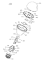
以下、本発明をその実施の形態を示す図面に基づいて説明する。図1は本実施の形態の照明装置100の外観図であり、図2は本実施の形態の照明装置100の要部分解斜視図であり、図3は本実施の形態の照明装置100の正面断面図であり、図4は本実施の形態の照明装置100の側面断面図である。照明装置100は、例えば、40W、60Wなどの電球型をなす。
Hereinafter, the present invention will be described with reference to the drawings illustrating embodiments thereof. FIG. 1 is an external view of a
図1に示すように、外観視において、照明装置100は、外部のソケットに嵌めて商用電源に電気的に接続するための口金10、照明装置100で発生する熱を放熱するため中空(筒状)のヒートシンク30、口金10とヒートシンク30とを連結するとともに両者を電気的に絶縁する円筒状の絶縁部材20、ヒートシンク30に後述する光源としてのLEDモジュールを保持するための略円板状の光源保持体40、略半球殻のカバー50などを備える。
As shown in FIG. 1, in an external view, the
以下、図2〜図4に従って具体的に説明する。口金10は、例えば、口金規格がE26のソケットであり中空部11を有する。口金10の周囲には、ねじ山を設けてある。なお、口金規格はE26以外のものでもよく、例えば、E17等の他の口金規格でもよい。
Hereinafter, it demonstrates concretely according to FIGS. The
絶縁部材20は、円筒状であって、例えば、ポリブチレンテレフタレート(以下、PBTと称する)樹脂製であり、耐熱性、耐薬品性、電気特性(絶縁性)、寸法安定性、成形性、難燃性などに優れている。なお、材質は、PBT樹脂に限定されるものではなく、ABS樹脂等の電気絶縁性を有する樹脂であればよい。
The
絶縁部材20の口金側には、口金10に内設される円筒状の接続部24を有する。接続部24には、口金10の内周面にねじ山が形成された雌ねじにねじ込んで螺合する雄ねじのねじ山241を接続部24の外周に形成してある。これにより、口金10と絶縁部材20とは螺合させるだけで取り付けることができるので、ネジを用いる必要がなく組み立て作業を簡略化することができる。なお、接続部24の口金10への接続方法は、ねじ山241を口金内部に形成した雌ねじに螺合する方法に限定されず、口金10の内壁に設けた切欠部に接続部24に形成したツメ状の係止部を係止させて接続する方法などであってもよい。
On the base side of the
また、絶縁部材20の接続部24には、2箇所に開口部25を形成してある。本実施の形態では、2つの開口部25は対向した位置関係となるべく接続部24の周囲2箇所に設けられる。これにより、接続部24の内部は、開口部25において接続部24自身で遮られることなく直接口金10で覆われる。なお、図2の例では、開口部25は矩形状であって切欠状をなすが、形状等はこれに限定されるものではない。例えば、切欠状ではなく、複数の孔を多数形成してもよい。なお、開口部25の数は、本実施の形態のように接続部24に2箇所設ける構成に限らず1箇所に設けてもよいし3箇所以上の複数箇所に設けてもよい。要するに接続部24の内部が直接口金10で覆われる部分が存在すればよい。
Moreover, the
絶縁部材20のヒートシンク側には、ヒートシンク30の開放部35に内挿される内挿部21を有する。内挿部21には、ヒートシンク30の固定片36に嵌合する嵌合部22を有する。すなわち、固定片36に嵌合部22を嵌合させるだけで、ヒートシンク30と絶縁部材20とを取り付けることができるので、ネジを用いる必要がなく組み立て作業を簡略化することができる。
On the heat sink side of the
絶縁部材20は、内周面に電源部80の電源基板81を挟持する挟持部26を有する。挟持部26は、絶縁部材20の内周面に対向して口金10側からヒートシンク30側の方向に2箇所設けられた直線状の溝である。2箇所の溝は、夫々絶縁部材20の内周面において口金10側からヒートシンク30側の方向に設けられた2つの直線状の凸部の間に形成される。挟持部26に、略矩形状の電源基板81の長手方向に沿った縁辺を嵌合させることにより、電源基板81を挟持することができる。電源基板81の縁辺を挟持部26で挟持させるだけで、電源基板81を絶縁部材20に固定することができ、電源基板81の取り付けのためにネジを用いる必要がなく組み立て作業を簡略化することができる。なお、挟持部26は、上述の2つの凸部による形成に限定されず、絶縁部材20の内周面に直線状の凹部からなる溝を削成してもよい。
The insulating
電源基板81の長手方向の縁辺の中途部には段差部811を設けてある。電源基板81を挟持部26に挿入した際に、段差部811が内挿部21の端部に当接する。これにより、電源基板81の段差部811が内挿部21の端部に当節した位置よりも奥に、電源基板81が絶縁部材20の内部に挿入されることを規制するので、電源基板81の位置決めを容易に行うことができる。本実施の形態では、電源基板81の絶縁部材20に挿入する側の端部が接続部24の端部とほぼ一致するように絶縁部材20への電源基板81の取り付け位置を決定することができる。これにより、電源部80の一部が絶縁部材20の内側に配置される。
A
電源部80は、LEDモジュール60に電力を供給する。電源部80は、電源基板81に複数の電気部品(電子部品も含む)82を実装してある。なお、電源部80の回路構成は後述する。
The
本実施の形態の照明装置100の光源であるLEDモジュール60は、矩形状の基体61と、基体61上に搭載された発光部としてのLED62を備える。LEDモジュール60は、例えば、セラミック基板の基体61に複数(例えば、30個、40個など)の白色光を発光するLEDチップからなるLED62を格子状に配置して複数のLED62を、蛍光体を含む樹脂で封止した所謂チップオンボード方式のLEDモジュールである。なお、LED62は、白色LEDに限定されず、電球色LEDでもよく、あるいは白色LEDと電球色LEDとを混在させてもよい。白色LEDと電球色LEDを混在させた場合には、各LEDの点灯状態を制御することにより、発光色を白色と電球色との間で変化させることができる。
An
なお、本発明に係る照明装置の光源は、前述のLEDモジュール60のような光源の基体としてのセラミック基板に光源の発光部としての複数のLEDチップを格子状に配置して複数のLEDチップを蛍光体を含む樹脂で封止したチップオンボード方式のLEDモジュールに限定されず、前述の基体として導体パターンが形成されたガラスエポキシ製等のプリント基板を用いてもよいし、発光部としてLEDチップとLEDチップを封止する封止樹脂と入力端子及び出力端子とを備えてなる所謂表面実装型のLEDを用いてもよい。
In addition, the light source of the illuminating device according to the present invention includes a plurality of LED chips arranged in a lattice pattern on a ceramic substrate as a light source substrate such as the
ヒートシンク30は、例えば、アルミニウムなどの熱伝導性に優れた金属製であって中空の筒状をなす。ヒートシンク30は、例えば、プレス加工により作製しており、ヒートシンク30の肉厚を薄くして軽量化を図ることができる。ヒートシンク30は、一端側にLEDモジュール60を装着する装着面34を有し、他端側には内挿部21をヒートシンクの中空部に内挿する円形状の開放部35を有する。なお、ヒートシンク30の作製の方法はプレス加工に限らず、ダイカスト加工であってもよい。
The
装着面34とLEDモジュール60との間には、LEDモジュール60(基体61)の寸法より大きい放熱シート70を配置してある。本実施の形態では、一例として、放熱シート70をLEDモジュールの基体61の寸法より大きくすることで、放熱シート70を、LEDモジュール60の電極とヒートシンク30との沿面距離が約3mmとなる寸法となるようにしている。放熱シート70の材質は、例えば、シリコーンゲルとすることができる。放熱シート70を基体61とヒートシンク30との間に密着させることにより、LEDモジュール60で発生した熱をヒートシンク30へ伝えることができ、ヒートシンク30で効率良く放熱することができる。
Between the mounting
また、基体61の寸法より大きい放熱シート70を設けることにより、基体61の端部から放熱シート70の端部までの距離を長くすることができるので、LEDモジュール60の電極とヒートシンク30との沿面距離を長くすることができ、絶縁耐圧の向上、各種規格で定められた絶縁距離(空間距離)を十分に確保することができる。なお、放熱シート70の寸法は、上述のように沿面距離が約3mmとなる寸法に限定されずLEDモジュール60の電極とヒートシンク30との絶縁距離が十分確保できる寸法であればよい。
Moreover, since the distance from the edge part of the base |
装着面34の中央付近には、LEDモジュール60と嵌合して位置決めする嵌合部である凹部33を形成してある。凹部33は、LEDモジュール60の基体61の形状に合わせた矩形状に形成してある。具体的には、凹部33の矩形の寸法を基体61よりわずかに大きくすることで基体61を嵌合可能にしてある。これにより、凹部33に基体61を嵌合することでLEDモジュール60を所定の位置に確実に取り付けることができ、位置決めを簡単に行うことができ取り付け作業性が向上する。
In the vicinity of the center of the mounting
装着面34には、LEDモジュール60の基体61の表面に設けられた電極に接続される配線(電線又は配線用フレキシブル基板など)を挿通してヒートシンク30内に収容される電源部80に導くための貫通部31を設けてある。
In order to guide the
また、装着面34には、光源保持体40に設けられた係止部44を係止するための係止孔32を3個形成してある。係止孔32の数は、3個に限定されるものではなく、2個、あるいは4個以上の複数個形成してもよい。
The mounting
光源保持体40は、円板状をなし、例えば、ポリカーボネート樹脂製である。光源保持体40は、ヒートシンク30に係止することにより、光源保持体40でLEDモジュール60をヒートシンク30に保持して装着する。つまり、光源保持体40は、ヒートシンク30にLED60を保持すべく係止部44を係止孔32に係止することで、ヒートシンク30に取り付けられる。これにより、LEDモジュール60をヒートシンク30に取り付けるためのネジが不要となり、部品点数の削減が可能となる。また、本実施の形態によれば、光源保持体40をヒートシンク30に係止させて取り付けるだけでLEDモジュール60の取り付け作業を行うことが可能であるので、従来技術のように複数のネジを夫々対応するネジ孔に螺着するという作業をする必要がなく、LEDモジュール60の取り付け作業が簡単になり作業性が従来よりも向上する。
The
より具体的には、光源保持体40は、ヒートシンク30の装着面34上に形成された係止孔32に係止する係止部44を備える。係止部44を係止孔32に係止させることにより、ネジを用いることなくLEDモジュール60をヒートシンク30に取り付けることができ、部品点数の削減とLEDモジュール60の取り付け作業が簡単になり作業性が従来よりも向上する。すなわち、係止部44を係止孔32に係止することで光源保持体40をヒートシンク30で係止してLEDモジュール60をヒートシンク30にネジを用いることなく装着することができ、さらに光源保持体40を取り付けると同時にLEDモジュール60をヒートシンク30との間に保持することができるので、LEDモジュール60の取り付け作業を容易にし、組み立て作業を簡略化することができる。
More specifically, the
また、光源保持体40は、中央付近にLEDモジュール60と嵌合してLEDモジュール60を位置決めする嵌合部としての嵌合孔41を備える。嵌合孔41は、基体61と略同寸法であって基体61と嵌合することでLEDモジュール60を位置決めする。LEDモジュール60の基体61を光源保持体40の嵌合孔41に嵌合させて、LEDモジュール60をヒートシンク30に装着して保持することができるので、LEDモジュール60を所定の位置に確実に取り付けることができ、位置決めを簡単に行うことができ取り付け作業性が向上する。
Further, the
さらに、嵌合孔41はLEDモジュール60の位置決めをすると共に、LEDモジュール60の周囲を嵌合孔41の内周部で取り付け位置を固定する。これにより、LEDモジュール60が光源保持体40に対して平行方向に移動してずれることを防ぐことが可能となる。
Further, the
光源保持体40は、嵌合孔41の周縁の一部に突起部42を備える。そして、基体61の一部を突起部42とヒートシンク30との間に配置する。すなわち、光源保持体40の嵌合孔41に嵌合したLEDモジュール60は、基体61がヒートシンク30と突起部42との間に挟まれることで保持されるので、ネジを用いることなく、確実にヒートシンク30に装着することができる。
The
すなわち、突起部42はヒートシンク30との間で基体61を挟持することで光源を保持するので、LEDモジュール60の光源保持体40に対して垂直方向に移動することを防ぎ、取り付け位置を固定する。したがって、突起部42によってLEDモジュール60が光源保持体40の嵌合孔41からから脱落してしまうことを防ぐことができる。
That is, since the
また、基体61及び嵌合孔41は、矩形状をなし、突起部42を、嵌合孔41の対角線上の対向する角部近傍の2箇所にそれぞれ設けてある。これにより、LEDモジュール60の基体61の対角線上の角部近傍でバランスよく基体61をヒートシンク30と突起部42とで挟むので、ネジを用いることなく、確実にヒートシンク30に装着して保持することができる。
Further, the
なお、突起部42の数は前述のように2個に限定されるものではなく、1個でも3個以上の複数個でもよい。例えば、突起部42を嵌合孔41の角部の4箇所に設けることで、LEDモジュール60の四隅をヒートシンク30との間で挟持するので、より安定的にLEDモジュール60をヒートシンク30との間で保持し、脱落する虞を低減することが可能となる。また、突起部42の平面視形状は矩形状に限定されるものではなく、LEDモジュール60をヒートシンク30との間で挟み込むことができれば、どのような形状であってもよい。また、突起部42の位置は、対角線上の角部近傍に限定されるものではなく、嵌合孔41の対向する辺縁に設けることもできる。
Note that the number of
上記のように光源保持体40は、LED62が搭載されていない基体61の周縁部を突起部42とヒートシンク30の間で保持することで、LEDモジュール60を保持している。これにより、光源保持体40は、LED62を覆わず露出した状態で、基体61にてLEDモジュール60を保持することでLED62からの光を取出す光取出し部としても機能する嵌合孔41を形成している。従って、光源保持体40は、ヒートシンク30との間にLEDモジュール60を挟んで保持してもLEDモジュール60からの光を取出す光取出し部である嵌合孔41を形成して、嵌合孔41から光を取出して照明することが可能となる。
As described above, the
ヒートシンク30は、LEDモジュール60の基体61上の電極に接続された配線を挿通する貫通部31を有する。また、光源保持体40は、貫通部31に嵌挿する嵌挿部43を有する。そして、嵌挿部43に前述の配線を挿通する挿通孔431を形成してある。すなわち、LEDモジュール60の基体61上の電極に接続された配線は、嵌挿部43に形成された挿通孔431を挿通してヒートシンク30内部に導くことができるので、基体61の発光部側に電極を設けたLEDモジュール60の配線を容易にすることができる。
The
また、嵌挿部43はヒートシンク30の貫通部31に嵌挿されるので、電線又は配線基板などの配線がヒートシンク30の貫通部31の周縁に存在する、例えば、金属製のバリ、角又はエッジなどに直接接触することがなく樹脂製の光源保持体40の嵌挿部43で保護される。つまり、嵌挿部43は貫通部31に挿通した配線がヒートシンク30のバリ、角又はエッジ等で損傷するのを保護する保護部として機能し、前述の配線が破損することを防止することができる。
Moreover, since the
光源保持体40は、例えば、酸化チタンなどの白色顔料を配合した光反射性の合成樹脂製である。白色顔料を配合した合成樹脂製の光源保持体40を備えることにより、反射膜の形成あるいは反射シートを設ける必要がなく、部品点数を削減することができ、組み立て作業性を向上させることができる。また、反射率が90〜95%程度の高反射率を得ることができるので、カバー50の内部で反射して光源保持体40側に戻ってきた光を、再度反射部を兼ねる光源保持体40で反射させて照明装置100の発光効率を向上させることができる。すなわち、光源保持体40は、光源を保持する機能と、カバー50から反射してきた光を反射する反射部としての機能とを兼ねるため、別途反射部を設ける必要をなくし部品点数の削減に寄与する。光源保持体40の材料には、例えば、住友ダウ製の「LR8031V」などを用いることができ、この場合には反射率は約95%程度となる。
The
なお、光源保持体40を前述のように反射部としても機能させるためには、光源保持体40を光反射性の合成樹脂製とする構成に限らず、前述の反射膜や反射シートを光源保持体40の表面に設ける構成であってもかまわない。但し、光源保持体40全体を光反射性の合成樹脂製とすることで、反射膜や反射シートを設ける構成に比べ劣化や磨耗による反射機能の低下の虞が低減する点で有利である。
In order to cause the
光源保持体40は、カバー50との当接面に凹部45を有する。
The
カバー50は、例えば、乳白色のポリカーボネート樹脂製であって、光源保持体40との当接面に凹部45に嵌合する突起部51を有する。凹部45に突起部51を嵌合させるだけで、光源保持体40とカバー50とを取り付けることができるので、ネジを用いる必要がなく組み立て作業を簡略化することができる。凹部45に突起部51嵌合することで、カバー50の位置決めを行えるとともに、カバー50が光源保持体40に対して回転することを防止することができる。
The
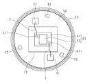
図5はヒートシンク30の装着面側の平面図である。図5の例では、装着面34上にLEDモジュール60及び放熱シート70を装着した様子を示し、光源保持体40は未着の状態を示す。
FIG. 5 is a plan view of the mounting surface side of the
LEDモジュール60の基体61上の電極611に接続された配線5は、嵌挿部43に形成された挿通孔431に挿通され(図5の例では不図示)、ヒートシンク30の貫通部31を通じてヒートシンク30内部に導くことができるので、基体61の発光部側に電極611を設けたLEDモジュール60を容易に取り付けることができる。また、嵌挿部43はヒートシンク30の貫通部31に嵌挿されるので、電線又は配線用フレキシブル基板などの配線5がヒートシンク30の貫通部31の、例えば、金属製のバリ、角又はエッジなどに直接接触することがなく樹脂製の光源保持体40の嵌挿部43で保護されるので、貫通部31で破損することを防止することができる。すなわち、嵌挿部43は貫通部31から配線5を保護する保護部である。
The
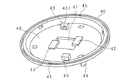
図6は光源保持体40のカバー側から見た斜視図であり、図7は光源保持体40のヒートシンク側から見た斜視図である。光源保持体40は、中央付近に基体61と略同寸法であって基体61が嵌合する嵌合孔41を備える。LEDモジュール60の基体61を光源保持体40の嵌合孔41に嵌合させて、LEDモジュール60をヒートシンク30に装着することができるので、LEDモジュール60を所定の位置に確実に取り付けることができ、位置合わせを簡単に行うことができ取り付け作業性が向上する。
6 is a perspective view of the
また、嵌合孔41の周縁の一部に突起部42を備える。そして、基体61の一部を突起部42とヒートシンク30との間に配置することができる。すなわち、光源保持体40の嵌合孔41に嵌合したLEDモジュール60は、基体61がヒートシンク30と突起部42との間に挟まれることで保持されるので、ネジを用いることなく、確実にヒートシンク30に装着することができる。
Further, a
また、図6等で示す本実施の形態の例では、嵌合孔41及び突起部42を設けることでLEDモジュール60が光源保持体40に対して平行及び垂直方向に動いてずれることを防止し、取り付け位置を固定する構成であるが、嵌合孔41又は突起部42を設けない構成とすることもできる。その場合の構成は、例えば、基体61の一部を、光源保持体40でヒートシンク30に押圧することでLEDモジュール60を保持することができる。つまり、LEDモジュール60を押圧し、ヒートシンク30又は光源保持体40との静止摩擦力によって、LEDモジュール60が光源保持体40に対して平行方向に移動することを防ぐことができる。
Further, in the example of the present embodiment shown in FIG. 6 and the like, the
また、光源保持体40を構成する部材の点数は本実施の形態のような1つに限らず、複数であってもよい。例えば、2つの部材からなる光源保持体が夫々基体61の両端2箇所をヒートシンク30との間で保持する構成にすることも可能である。
Further, the number of members constituting the
本実施の形態のように、特に発光部を搭載する光源の基体がセラミック製である場合、基体を直接ネジで固定すると、ネジを取り付けた部分に応力が集中し基体が破損する虞がある。本願に係る照明装置では、基体がセラミック製である場合でも、基体61を光源保持体40にてヒートシンク30との間で基体に圧力をかけることなく嵌合孔41及び突起部42により光源モジュール60の周囲を拘束するだけで保持することが可能であるので、基体に設けられたネジ孔にネジを締め付けることにより前記ネジ孔に応力が集中して基体が破損するという虞を低減することができる。
As in this embodiment, particularly when the base of the light source on which the light emitting unit is mounted is made of ceramic, if the base is directly fixed with screws, stress may concentrate on the portion where the screws are attached and the base may be damaged. In the lighting device according to the present application, even when the base is made of ceramic, the
また、セラミック製の前記光源の基体に直接ネジ孔を設けて該ネジ孔にネジを螺合してヒートシンクに光源を固定する場合、セラミックのような脆性破壊を起こしやすい材料ではネジ孔の加工精度が悪く、ネジ孔を加工しにくいという問題がある。しかし本実施の形態の光源保持体40で光源をヒートシンク30に保持する構成であれば、基体にネジ孔を設ける必要がなく、容易に光源をヒートシンク30に取り付けることが可能である。
In addition, when a screw hole is directly formed in the base of the light source made of ceramic and the light source is fixed to the heat sink by screwing the screw into the screw hole, the processing accuracy of the screw hole in a material that easily causes brittle fracture such as ceramic However, there is a problem that it is difficult to process the screw hole. However, if the
嵌挿部43は、ほぼ直方体状をなし、上面46側には、上面46と交差する方向に挿通孔431を形成してあり、下面47側には、下面47と平行に挿通孔431を形成してある。嵌挿部43の下面47から突出した部分は、ヒートシンク30の貫通部31に嵌挿される。当該突出した部分の寸法は、ヒートシンク30の装着面34の板厚と同等若しくは大きくしてある。挿通孔431の連通方向を、光源保持体40の上面46側と下面47側との間で略90度に曲がるようにすることで、配線ルートに沿って配線5を導くことができ、配線5に不要な応力等がかかることを抑制することができる。
The
係止部44の縦断面は、略L字状をなし、板厚の薄いばね部441と、板厚の厚い止め部442とで構成される。止め部442は、先端に向かって板厚が薄くなるようテーパ状をなし、係止部44が係止孔32に入り易くなるようにしてある。係止部44を係止孔32に挿入する際、ばね部441の付勢力に反して、係止部44が外側に徐々に広がるようになり、止め部442が係止孔32を完全に挿通した後は、ばね部441の付勢力で元の形状に戻り、止め部442が係止孔32の周辺部に引っかかり、光源保持体40が確実にヒートシンク30に係止される。
The vertical section of the locking
なお、本実施の形態のばね部441及び止め部442をヒートシンク30に形成し、止め部442が係止する係止孔32を光源保持体40に形成して、光源保持体40をヒートシンク30に係止することも可能である。
The
図8はカバー50の一部断面図である。カバー50は、中空のドーム状をなし、光源保持体40と当接する円周部52の、例えば、3箇所に光源保持体40との当接面に凹部45に嵌合する突起部51を有する。光源保持体40の凹部45に突起部51を嵌合させるだけで、光源保持体40とカバー50とを取り付けることができるので、ネジを用いる必要がなく組み立て作業を簡略化することができる。
FIG. 8 is a partial cross-sectional view of the
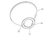
図9はヒートシンク30の開放部35側の斜視図である。ヒートシンク30は、開放部35に周設された固定片36を有する。固定片36は、開放部35の回りにヒートシンク30の内側に向かって立設された環状の部材である。また、固定片36の一部には、切欠部37を形成してある。
FIG. 9 is a perspective view of the
なお、図9等の例では、不図示であるが、放熱効果を高めるために、ヒートシンク30の表面に凹凸を形成して、表面積を増加して外気との接触面積を増加させることができる。凹凸の模様は適宜設定することができる。
Although not shown in the example of FIG. 9 and the like, in order to enhance the heat dissipation effect, irregularities can be formed on the surface of the
図10は絶縁部材20のヒートシンク側から見た斜視図であり、図11は絶縁部材20の口金側から見た斜視図である。内挿部21の外周の一部には、切欠部37と略同寸法であって矩形状の位置決め部23を形成してある。絶縁部材20にヒートシンク30を装着する場合に、内挿部21を開放部35に挿入する際、位置決め部23と切欠部37の位置を合わせることにより、内挿部21が開放部35内で自由に回転することを防止でき、確実に位置決めを行うことができる。
10 is a perspective view of the insulating
嵌合部22の縦断面は、略L字状をなし、板厚の薄いばね部221と、板厚の厚い止め部222とで構成される。止め部222は、先端に向かって板厚が薄くなるようテーパ状をなし、嵌合部22が固定片36に嵌合し易くなるようにしてある。嵌合部22を固定片36に嵌合する際、ばね部221の付勢力に反して、嵌合部22が内側に徐々に狭まるようになり、止め部222が固定片36の周端部を超えた後は、ばね部221の付勢力で元の形状に戻り、止め部222が固定片36の周端部に引っかかり、絶縁部材20が確実にヒートシンク30に装着される。
The vertical section of the
図12は電源部80の回路構成の一例を示すブロック図である。電源部80は、商用電源などから侵入してくるノイズを除去するためのノイズフィルタ回路821、交流電圧を整流して直流電圧に変換する整流回路822、整流回路822から出力された直流電圧を所要の直流電圧に変換するDC/DCコンバータ823、DC/DCコンバータ823から出力された直流電圧に対してパルス幅変調を行うことによりLEDモジュール60に供給する電流(電力)を制御するPWM回路824、電源部80の制御を行う制御用マイクロコンピュータ825などを備えている。上述の各部は、電気部品82で構成される。
FIG. 12 is a block diagram illustrating an example of a circuit configuration of the
電源部80は、発熱部品を含む。発熱部品は、例えば、整流回路822内の整流素子、DC/DCコンバータ823内のスイッチング素子(FET、トランジスタ)、PWM回路824内のスイッチング素子(FET、トランジスタ)などである。
The
図13は電源部80の配置例を示す要部側面図である。図13では、絶縁部材20に電源部80の電源基板81を装着した状態を示す。また、説明の便宜上、口金10は外した状態としている。
FIG. 13 is a side view of an essential part showing an arrangement example of the
図13に示すように、円筒状の絶縁部材20は、口金10側に口金10に内設される円筒状の接続部24を有し、接続部24は、開口部25を形成してある。電源部80の一部を接続部24の内側に配置してある。すなわち、電源部80の一部が開口部25に対向させた状態で口金10の中空部に収容されている。接続部24に開口部25を設け、接続部24の内側に電源部80の一部を開口部25に対向させて配置してあるので、電源部80の一部は、絶縁部材20(接続部24)で遮られることなく口金10の内側に配置されている。これにより、電源部80で発生した熱は、接続部24で遮られることなく開口部25を介して口金10に伝導し、口金10を介して外部へ放熱することができ、電源部80で発生する熱を効率良く放熱することができる。なお、本実施の形態では、電源部80の一部を口金10の中空部に収容しているが、電源部80全部を前記中空部に収容してもよく、電源部80の少なくとも一部が前記中空部に収容されていればよい。
As shown in FIG. 13, the cylindrical insulating
また、電源部80の一部として、発熱部品、例えば、整流回路822、PWM回路824などの整流素子又はスイッチング素子(FET、トランジスタ)などの少なくとも1つを口金側に配置し、開口部25に対向させることにより、発熱量の大きい発熱部品を接続部24の周壁で遮られることなく口金10に近接させることができる。これにより発熱部品から口金10へ開口部25を介して熱が伝わり易くなり、熱伝導の効率を高めることが可能となるので、発熱部品で発生した熱を口金10から外部へ効率的に放熱することができる。
Further, as a part of the
また、接続部24に開口部25を設けることで、開口部25を通じて口金10の内側に密着し、電源部80の一部を覆うように接続部24内に充填された樹脂製の熱伝導部材28を備えることができる。開口部25によって口金10と口金10の中空部に収容される電源部80の一部とが接続部24で遮られることなく対向するので、開口部25を間に介して直接口金10と電源部80の一部とを熱伝導部材28で熱的に接続することが可能となる。従って、開口部25を形成することで、熱伝導部材28を容易に電源部80と口金10とを熱的に接続した状態で接続部24内に設けることが可能となる。
Further, by providing the opening
熱伝導部材28は、例えば、シリコーンゲルなどの放熱パテでもよく、あるいは、ポリウレタンなどのポッティング材でもよい。放熱パテは、比較的粘性が大きいので、開口部25の開口面積を大きくした方が、放熱パテが口金10の内側に密着しやすい。また、ポッティング材は、比較的粘性が小さいので、開口部25として多数の孔を設けることで、各孔からポッティング材を口金10の内側に密着させることができる。すなわち、熱伝導部材28は電源部80と口金10とを熱的に接続すべく、接続部24内に設けることができる熱伝導の良好な樹脂であればよい。
The
電源部80の一部(発熱部品など)を覆う熱伝導部材28は、開口部25を通じて直接口金10に密着するので、熱伝導部材28を介して電源部80で発生した熱を口金10から外部へ放熱することができる。
The
なお、本実施の形態では、熱伝導部材28は、接続部24内全体に充填されているが、発熱部品等の電源部80の一部と口金10を熱的に接続していれば、接続部24内に部分的に設けられるようにしてもよい。また、本実施の形態では、発熱部品は、開口部25に対向させているが、発熱部品を開口部25に対向させず口金10側に配置するのみの構成であってもよい。つまり、開口部25を通じて発熱部品と口金10とを熱伝導部材28で熱的に接続可能であれば、発熱部品を開口部25に対向させなくてもよい。但し、発熱部品を開口部25に対向させる方が、発熱部品が接続部24で遮られることがなく熱伝導部材28で口金10と発熱部品とを熱的に接続することが容易になる点で好ましい。
In the present embodiment, the
また、電源基板81の一部を接続部24内に配置しているので、ヒートシンク30内に収容される電源基板81の寸法を短くすることができ、ヒートシンク30の長さ(高さ)寸法を小さくすることができ、照明装置100の小型化を図ることができる。
In addition, since a part of the
なお、本実施の形態では、図11等に示すように開口部25を2箇所設ける構成であるが、開口部25は1箇所に設ける構成でもよい。開口部25を2箇所設ける場合には、電源基板81を両面実装タイプとして、電源基板の両面に実装された発熱部品からの熱を口金10に熱伝導部材28で伝導することができ、一層放熱効果を高めることができる。
In the present embodiment, two
上述の実施の形態では、電球型の照明装置について説明したが、照明装置の形状は電球型に限定されるものでなく、埋め込式照明装置(所謂ダウンライト)等他の形状の照明装置であってもよい。また、光源としてLEDモジュールを備える照明装置について説明したが、光源はLEDモジュールに限定されるものではなく、面発光を有する発光素子であれば、EL(Electro Luminescence)などでもよい。 In the above-described embodiment, the bulb-type illumination device has been described. However, the shape of the illumination device is not limited to the bulb-type illumination device, and other shapes of illumination devices such as an embedded illumination device (so-called downlight) can be used. There may be. Moreover, although the illuminating device provided with the LED module as the light source has been described, the light source is not limited to the LED module, and may be EL (Electro Luminescence) or the like as long as it is a light emitting element having surface emission.
上述の実施の形態では、装着面34に光源としてのLEDモジュール60を1つ装着する構成であったが、これに限定されるものではなく、複数のLEDモジュールを円周状、格子状、あるいは直線状に配置するものでもよい。この場合には、LEDモジュールの数に応じて、LEDモジュールを嵌合させる嵌合孔を設けた光源保持体で複数のLEDモジュールをヒートシンクに保持すればよい。
In the above-described embodiment, one
また、上述したチップオンボード方式以外の光源である、基体としてのプリント基板に発光部としての表面実装型LEDを実装した光源であれば、発光部の数に応じた数の嵌合孔が形成された光源保持体で、発光部である複数の表面実装型LEDを嵌合孔に夫々嵌合させて光源をヒートシンクに保持する構成とすることが可能である。 In addition, if the light source is a light source other than the above-described chip-on-board method and a surface-mounted LED as a light emitting part is mounted on a printed circuit board as a base, the number of fitting holes corresponding to the number of light emitting parts is formed. With the light source holder thus formed, it is possible to adopt a configuration in which a plurality of surface-mounted LEDs that are light emitting portions are respectively fitted in fitting holes to hold the light source on the heat sink.
上述の実施の形態では、カバー50と光源保持体40、光源保持体40とヒートシンク30、ヒートシンク30と絶縁部材20、絶縁部材と口金10等のいずれも簡単に嵌め込むだけで装着することができ、ネジを一切不要とするので組み立て作業の作業性が従来に比べて向上する。なお、強度を補強する目的で、カバー50と光源保持体40、光源保持体40とヒートシンク30、ヒートシンク30と絶縁部材20、絶縁部材と口金10等の装着時に接着剤を用いることもできる。
In the above-described embodiment, the
10 口金
11 中空部
20 絶縁部材
21 内挿部
22 嵌合部
23 位置決め部
24 接続部
25 開口部
26 挟持部
28 熱伝導部材
30 ヒートシンク
31 貫通部
32 係止孔
33 凹部
34 装着面
35 開放部
36 固定片
40 光源保持体
41 嵌合孔
42 突起部
43 嵌挿部
431 挿通孔
44 係止部
45 凹部
50 カバー
51 突起部
60 LEDモジュール(光源)
61 基体
62 LED
70 放熱シート
80 電源部
81 電源基板
82 電気部品
822 整流回路
823 DC/DCコンバータ
824 PWM回路
DESCRIPTION OF
61
DESCRIPTION OF
本発明に係る照明装置は、光源と、該光源に電力を供給する電源部と、前記光源からの熱を放熱するヒートシンクと、前記電源部の少なくとも一部を内部に収容する口金と、該口金と前記ヒートシンクとの間にある絶縁部材とを備える照明装置において、前記絶縁部材は、一端側に、前記口金の内側に接続される接続部を有し、該接続部は、前記口金の内側に配置される側面に開口部を有し、前記電源部は、前記口金側に配置される発熱部品を有し、該発熱部品は、交流を整流する整流素子又は該整流素子で整流した直流をスイッチングするスイッチング素子の少なくとも一方を含み、かつ少なくとも一部が前記開口部に対向配置されてあり、前記開口部を通じて前記発熱部品からの熱を前記口金に伝導する樹脂からなる熱伝導部材を備えることを特徴とする。 An illumination device according to the present invention includes a light source, a power supply unit that supplies power to the light source, a heat sink that dissipates heat from the light source, a base that houses at least a part of the power supply unit, and the base And an insulating member between the heat sink, the insulating member has a connecting portion connected to the inside of the base on one end side, and the connecting portion is on the inside of the base. have a opening on the side surface which is disposed, the power supply unit includes a heat generating component disposed on the cap side, the heat generating components, switching the direct current rectified by the rectifying element or rectifying elements for rectifying AC includes at least one switching element, and Yes at least partially placed opposite to the opening, Ru with a heat conduction member made of resin to conduct heat from the heat generating component to the mouthpiece through the opening And wherein the door.
本発明にあっては、口金の内部に電源部の少なくとも一部が収容され、絶縁部材は、一端側に口金の内側に接続される接続部を有し、接続部は、電源部からの熱を口金に伝導するための開口部を有する。口金の内側に接続する接続部に開口部を設けてあるので、電源部の一部は、絶縁部材で遮られることなく口金の内側に配置される。これにより、電源部で発生した熱を、開口部を介して口金に伝導することができ、電源部で発生する熱を効率良く口金から放熱することができる。
また、開口部を通じて口金と電源部とを熱的に接続する、樹脂からなる熱伝導部材を備える。すなわち、口金と電源部とを熱的に接続する熱伝導部材は、開口部を通じて直接口金に密着するので、熱伝導部材を介して電源部で発生した熱を口金へ伝導することができる。
また、電源部は、口金側に配置される発熱部品を有する。これにより、発熱部品を口金に近接させることが可能となるので、発熱部品で発生した熱を効率的に口金に伝導し、口金から外部へ放熱することができる。
さらに、発熱部品は、交流を整流する整流素子又は整流素子で整流した直流をスイッチングするスイッチング素子の少なくとも一方を含む。これにより、発熱部品で発生した熱を口金から外部へ放熱することができる。
In the present invention, at least a part of the power supply unit is accommodated in the base, the insulating member has a connection part connected to the inner side of the base on one end side, and the connection part is a heat from the power supply part. Has an opening for conducting to the base. Since the opening is provided in the connection part connected to the inside of the base, a part of the power supply part is arranged inside the base without being blocked by the insulating member. Thereby, the heat generated in the power supply unit can be conducted to the base through the opening, and the heat generated in the power supply unit can be efficiently radiated from the base.
In addition, a heat conduction member made of a resin is provided that thermally connects the base and the power source through the opening. That is, since the heat conductive member that thermally connects the base and the power supply unit is in close contact with the base directly through the opening, heat generated in the power supply unit can be conducted to the base through the heat conductive member .
The power supply unit has a heat generating component arranged on the base side. Thereby, since it becomes possible to make a heat-emitting component adjoin to a nozzle | cap | die, the heat | fever which generate | occur | produced in the heat-emitting component can be efficiently conducted to a nozzle | cap | die, and it can thermally radiate from a nozzle | cap | die to the exterior .
Furthermore, the heat generating component includes at least one of a rectifying element that rectifies alternating current or a switching element that switches direct current rectified by the rectifying element. Thereby, the heat generated in the heat generating component can be radiated from the base to the outside .
本発明に係る照明装置は、前記接続部は、対向した2つの開口部を前記側面に有することを特徴とする。 Lighting device according to the present invention, the connecting section is characterized Rukoto to have a two openings opposed to the side surface.
絶縁部材20は、内周面に電源部80の電源基板81を挟持する挟持部26を有する。挟持部26は、絶縁部材20の内周面に対向して口金10側からヒートシンク30側の方向に2箇所設けられた直線状の溝である。2箇所の溝は、夫々絶縁部材20の内周面において口金10側からヒートシンク30側の方向に設けられた2つの直線状の凸部の間に形成される。挟持部26に、略矩形状の電源基板81の長手方向に沿った縁辺を嵌合させることにより、電源基板81を挟持することができる。電源基板81の縁辺を挟持部26で挟持させるだけで、電源基板81を絶縁部材20に固定することができ、電源基板81の取り付けのためにネジを用いる必要がなく組み立て作業を簡略化することができる。なお、挟持部26は、上述の2つの凸部による形成に限定されず、絶縁部材20の内周面に直線状の凹部からなる溝を作成してもよい。
The insulating
Claims (4)
前記絶縁部材は、
一端側に、前記口金の内側に接続される接続部を有し、
該接続部は、
前記電源部からの熱を前記口金に伝導するための開口部を有することを特徴とする照明装置。 A light source, a power source that supplies power to the light source, a heat sink that dissipates heat from the light source, a base that houses at least a portion of the power source, and a gap between the base and the heat sink In a lighting device comprising an insulating member,
The insulating member is
On one end side, it has a connection part connected to the inside of the base,
The connection is
An illuminating device having an opening for conducting heat from the power source to the base.
前記口金側に配置される発熱部品を有し、
前記熱伝導部材は、
前記発熱部品からの熱を前記口金に伝導することを特徴とする請求項2に記載の照明装置。 The power supply unit is
It has a heat generating component arranged on the base side,
The heat conducting member is
The lighting device according to claim 2, wherein heat from the heat generating component is conducted to the base.
交流を整流する整流素子又は該整流素子で整流した直流をスイッチングするスイッチング素子の少なくとも一方を含むことを特徴とする請求項3に記載の照明装置。 The heat generating component is
The lighting device according to claim 3, comprising at least one of a rectifying element that rectifies alternating current or a switching element that switches direct current rectified by the rectifying element.
Priority Applications (5)
| Application Number | Priority Date | Filing Date | Title |
|---|---|---|---|
| JP2010124894A JP4854798B2 (en) | 2010-05-31 | 2010-05-31 | Lighting device |
| EP11789526.8A EP2578925B1 (en) | 2010-05-31 | 2011-04-01 | Lighting apparatus |
| PCT/JP2011/058389 WO2011152116A1 (en) | 2010-05-31 | 2011-04-01 | Lighting device |
| CN2011800245094A CN102893080A (en) | 2010-05-31 | 2011-04-01 | Lighting device |
| US13/700,760 US20130082595A1 (en) | 2010-05-31 | 2011-04-01 | Lighting apparatus |
Applications Claiming Priority (1)
| Application Number | Priority Date | Filing Date | Title |
|---|---|---|---|
| JP2010124894A JP4854798B2 (en) | 2010-05-31 | 2010-05-31 | Lighting device |
Publications (2)
| Publication Number | Publication Date |
|---|---|
| JP2011253637A true JP2011253637A (en) | 2011-12-15 |
| JP4854798B2 JP4854798B2 (en) | 2012-01-18 |
Family
ID=45066502
Family Applications (1)
| Application Number | Title | Priority Date | Filing Date |
|---|---|---|---|
| JP2010124894A Active JP4854798B2 (en) | 2010-05-31 | 2010-05-31 | Lighting device |
Country Status (5)
| Country | Link |
|---|---|
| US (1) | US20130082595A1 (en) |
| EP (1) | EP2578925B1 (en) |
| JP (1) | JP4854798B2 (en) |
| CN (1) | CN102893080A (en) |
| WO (1) | WO2011152116A1 (en) |
Cited By (4)
| Publication number | Priority date | Publication date | Assignee | Title |
|---|---|---|---|---|
| JP2014179244A (en) * | 2013-03-14 | 2014-09-25 | Panasonic Corp | Light source of lighting and lighting device |
| TWI499740B (en) * | 2012-06-21 | 2015-09-11 | Acbel Polytech Inc | Light emitting diode bulb |
| JP2015179633A (en) * | 2014-03-19 | 2015-10-08 | 株式会社デンソー | Light source device |
| JP2016225130A (en) * | 2015-05-29 | 2016-12-28 | 岩崎電気株式会社 | lamp |
Families Citing this family (12)
| Publication number | Priority date | Publication date | Assignee | Title |
|---|---|---|---|---|
| JP4963736B2 (en) * | 2010-10-28 | 2012-06-27 | 日本航空電子工業株式会社 | Lighting device |
| JP6176895B2 (en) * | 2012-04-04 | 2017-08-09 | アイリスオーヤマ株式会社 | LED lamp |
| CN103527942B (en) * | 2012-07-04 | 2016-03-30 | 康舒科技股份有限公司 | LED ball lamp |
| JP2014029778A (en) * | 2012-07-31 | 2014-02-13 | Funai Electric Co Ltd | Illuminating device and illuminating device manufacturing method |
| CN103968267A (en) * | 2013-01-30 | 2014-08-06 | 新世纪光电股份有限公司 | LED light source element and illumination device using same |
| US20140307427A1 (en) * | 2013-04-11 | 2014-10-16 | Lg Innotek Co., Ltd. | Lighting device |
| DE202013007592U1 (en) * | 2013-08-26 | 2013-09-06 | Osram Gmbh | Semiconductor lamp with heat-conducting body between driver and driver housing |
| CN104296086A (en) * | 2014-11-06 | 2015-01-21 | 欧普照明股份有限公司 | LED lamp and heat radiator |
| CN104676513A (en) * | 2015-03-27 | 2015-06-03 | 立达信绿色照明股份有限公司 | Electric connection structure of lamp holder |
| CN105202487B (en) * | 2015-10-20 | 2022-10-25 | 漳州立达信灯具有限公司 | Bulb shell fixing structure |
| CN106439559A (en) * | 2016-12-08 | 2017-02-22 | 厦门海莱照明有限公司 | Lamp |
| CN108469010A (en) * | 2017-02-23 | 2018-08-31 | 黄子恒 | The high-quality LED light cooling mechanism curable type the core of the card of low cost |
Citations (8)
| Publication number | Priority date | Publication date | Assignee | Title |
|---|---|---|---|---|
| JP2009059707A (en) * | 2005-07-12 | 2009-03-19 | Toshiba Lighting & Technology Corp | Self-ballasted fluorescent lamp, and illuminating device |
| WO2009051128A1 (en) * | 2007-10-16 | 2009-04-23 | Toshiba Lighting & Technology Corporation | Light emitting element lamp and lighting equipment |
| JP2009135036A (en) * | 2007-11-30 | 2009-06-18 | Toshiba Lighting & Technology Corp | Compact self-ballasted fluorescent lamp, and lighting fixture |
| WO2009157285A1 (en) * | 2008-06-27 | 2009-12-30 | 東芝ライテック株式会社 | Light-emitting element lamp and lighting fixture |
| JP2010010134A (en) * | 2009-06-24 | 2010-01-14 | Toshiba Lighting & Technology Corp | Light emitting element lamp, and luminaire |
| JP2010033959A (en) * | 2008-07-30 | 2010-02-12 | Toshiba Lighting & Technology Corp | Bulb type lamp |
| JP2010086973A (en) * | 2005-04-08 | 2010-04-15 | Toshiba Lighting & Technology Corp | Self-ballasted lamp |
| JP2010086713A (en) * | 2008-09-30 | 2010-04-15 | Toshiba Lighting & Technology Corp | Bulb-type lamp |
Family Cites Families (20)
| Publication number | Priority date | Publication date | Assignee | Title |
|---|---|---|---|---|
| US6794801B2 (en) * | 2001-10-31 | 2004-09-21 | Toshiba Lighting & Technology Corporation | Compact selfballasted fluorescent lamp and luminaire |
| US7758223B2 (en) * | 2005-04-08 | 2010-07-20 | Toshiba Lighting & Technology Corporation | Lamp having outer shell to radiate heat of light source |
| CN100590345C (en) * | 2005-07-07 | 2010-02-17 | 东芝照明技术株式会社 | Bulb type fluorescent lamp and illuminator |
| US7766512B2 (en) * | 2006-08-11 | 2010-08-03 | Enertron, Inc. | LED light in sealed fixture with heat transfer agent |
| EP2163808B1 (en) * | 2007-05-23 | 2014-04-23 | Sharp Kabushiki Kaisha | Lighting device |
| CN101368719B (en) * | 2007-08-13 | 2011-07-06 | 太一节能系统股份有限公司 | LED lamp |
| CN201163608Y (en) * | 2008-01-03 | 2008-12-10 | 厦门星迈科技有限公司 | Lamp bulb type energy saving lamp structure |
| JP5353216B2 (en) | 2008-01-07 | 2013-11-27 | 東芝ライテック株式会社 | LED bulb and lighting fixture |
| US20110001417A1 (en) * | 2008-01-15 | 2011-01-06 | Albert Stekelenburg | LED bulb with heat removal device |
| CN101545620A (en) * | 2008-03-26 | 2009-09-30 | 秦文隆 | Led lamp |
| CN102175000B (en) * | 2008-07-30 | 2013-11-06 | 东芝照明技术株式会社 | Lamp and lighting equipment |
| US8427059B2 (en) * | 2008-07-31 | 2013-04-23 | Toshiba Lighting & Technology Corporation | Lighting device |
| JP2010040221A (en) * | 2008-07-31 | 2010-02-18 | Toshiba Lighting & Technology Corp | Self-ballasted lamp |
| US20100109499A1 (en) * | 2008-11-03 | 2010-05-06 | Vilgiate Anthony W | Par style lamp having solid state light source |
| EP2214456A1 (en) * | 2009-01-22 | 2010-08-04 | Nanker(Guang Zhou)Semiconductor Manufacturing Corp. | LED lamp circuit |
| US8057075B2 (en) * | 2009-03-13 | 2011-11-15 | Sunonwealth Electric Machine Industry Co., Ltd. | Lamp device |
| CN201448637U (en) * | 2009-05-08 | 2010-05-05 | 深圳市世峰科技有限公司 | Radiating LED lamp bulb |
| US20100320892A1 (en) * | 2009-06-19 | 2010-12-23 | Chih-Ming Yu | Heat dissipation enhanced led lamp for spotlight |
| US9030120B2 (en) * | 2009-10-20 | 2015-05-12 | Cree, Inc. | Heat sinks and lamp incorporating same |
| US8434906B2 (en) * | 2010-02-23 | 2013-05-07 | General Electric Company | Lighting system with thermal management system |
-
2010
- 2010-05-31 JP JP2010124894A patent/JP4854798B2/en active Active
-
2011
- 2011-04-01 CN CN2011800245094A patent/CN102893080A/en active Pending
- 2011-04-01 US US13/700,760 patent/US20130082595A1/en not_active Abandoned
- 2011-04-01 WO PCT/JP2011/058389 patent/WO2011152116A1/en active Application Filing
- 2011-04-01 EP EP11789526.8A patent/EP2578925B1/en not_active Not-in-force
Patent Citations (9)
| Publication number | Priority date | Publication date | Assignee | Title |
|---|---|---|---|---|
| JP2010086973A (en) * | 2005-04-08 | 2010-04-15 | Toshiba Lighting & Technology Corp | Self-ballasted lamp |
| JP2009059707A (en) * | 2005-07-12 | 2009-03-19 | Toshiba Lighting & Technology Corp | Self-ballasted fluorescent lamp, and illuminating device |
| WO2009051128A1 (en) * | 2007-10-16 | 2009-04-23 | Toshiba Lighting & Technology Corporation | Light emitting element lamp and lighting equipment |
| JP2009117342A (en) * | 2007-10-16 | 2009-05-28 | Toshiba Lighting & Technology Corp | Light-emitting element lamp, and lighting fixture |
| JP2009135036A (en) * | 2007-11-30 | 2009-06-18 | Toshiba Lighting & Technology Corp | Compact self-ballasted fluorescent lamp, and lighting fixture |
| WO2009157285A1 (en) * | 2008-06-27 | 2009-12-30 | 東芝ライテック株式会社 | Light-emitting element lamp and lighting fixture |
| JP2010033959A (en) * | 2008-07-30 | 2010-02-12 | Toshiba Lighting & Technology Corp | Bulb type lamp |
| JP2010086713A (en) * | 2008-09-30 | 2010-04-15 | Toshiba Lighting & Technology Corp | Bulb-type lamp |
| JP2010010134A (en) * | 2009-06-24 | 2010-01-14 | Toshiba Lighting & Technology Corp | Light emitting element lamp, and luminaire |
Cited By (4)
| Publication number | Priority date | Publication date | Assignee | Title |
|---|---|---|---|---|
| TWI499740B (en) * | 2012-06-21 | 2015-09-11 | Acbel Polytech Inc | Light emitting diode bulb |
| JP2014179244A (en) * | 2013-03-14 | 2014-09-25 | Panasonic Corp | Light source of lighting and lighting device |
| JP2015179633A (en) * | 2014-03-19 | 2015-10-08 | 株式会社デンソー | Light source device |
| JP2016225130A (en) * | 2015-05-29 | 2016-12-28 | 岩崎電気株式会社 | lamp |
Also Published As
| Publication number | Publication date |
|---|---|
| JP4854798B2 (en) | 2012-01-18 |
| WO2011152116A1 (en) | 2011-12-08 |
| EP2578925A4 (en) | 2014-01-15 |
| CN102893080A (en) | 2013-01-23 |
| US20130082595A1 (en) | 2013-04-04 |
| EP2578925A1 (en) | 2013-04-10 |
| EP2578925B1 (en) | 2017-05-31 |
Similar Documents
| Publication | Publication Date | Title |
|---|---|---|
| JP4854798B2 (en) | Lighting device | |
| JP5052647B2 (en) | Lighting device | |
| JP4926262B2 (en) | Lighting device | |
| JP5757214B2 (en) | LED lighting device | |
| JP2013175350A (en) | Light-emitting device and lighting fixture using the same | |
| US20150098229A1 (en) | Illumination device | |
| JP5501543B1 (en) | Light bulb type lighting device | |
| JP6803553B2 (en) | Lighting device | |
| JP6497658B2 (en) | lighting equipment | |
| JP2014072154A (en) | Light source for lighting and lighting device | |
| JP5999558B2 (en) | Illumination light source and illumination device | |
| JP5501542B2 (en) | Light bulb type lighting device | |
| JP5517014B2 (en) | Lamp with lamp and lighting equipment | |
| JP2012199256A (en) | Lighting system | |
| WO2013128733A1 (en) | Light-emitting device, and illumination apparatus using same | |
| JP2014099423A (en) | Bulb type lighting system | |
| JP2012181947A (en) | Led unit, and lighting fixture using the same | |
| JP2012059494A (en) | Bulb-shaped lamp and lighting fixture | |
| JP5906405B2 (en) | Illumination light source and illumination device | |
| JP6115859B2 (en) | Illumination light source and illumination device | |
| JP6011863B2 (en) | Illumination light source and illumination device | |
| JP2014072153A (en) | Light source for lighting and lighting device |
Legal Events
| Date | Code | Title | Description |
|---|---|---|---|
| TRDD | Decision of grant or rejection written | ||
| A01 | Written decision to grant a patent or to grant a registration (utility model) |
Free format text: JAPANESE INTERMEDIATE CODE: A01 Effective date: 20111004 |
|
| A01 | Written decision to grant a patent or to grant a registration (utility model) |
Free format text: JAPANESE INTERMEDIATE CODE: A01 |
|
| A61 | First payment of annual fees (during grant procedure) |
Free format text: JAPANESE INTERMEDIATE CODE: A61 Effective date: 20111025 |
|
| FPAY | Renewal fee payment (event date is renewal date of database) |
Free format text: PAYMENT UNTIL: 20141104 Year of fee payment: 3 |
|
| R150 | Certificate of patent or registration of utility model |
Ref document number: 4854798 Country of ref document: JP Free format text: JAPANESE INTERMEDIATE CODE: R150 Free format text: JAPANESE INTERMEDIATE CODE: R150 |