JP2011246800A - Membrane-electrode assembly, electrolytic cell using the same, apparatus and method for producing ozone water, disinfection method, and method for treating waste water or waste fluid - Google Patents
Membrane-electrode assembly, electrolytic cell using the same, apparatus and method for producing ozone water, disinfection method, and method for treating waste water or waste fluid Download PDFInfo
- Publication number
- JP2011246800A JP2011246800A JP2010197149A JP2010197149A JP2011246800A JP 2011246800 A JP2011246800 A JP 2011246800A JP 2010197149 A JP2010197149 A JP 2010197149A JP 2010197149 A JP2010197149 A JP 2010197149A JP 2011246800 A JP2011246800 A JP 2011246800A
- Authority
- JP
- Japan
- Prior art keywords
- cathode
- anode
- water
- membrane
- polymer electrolyte
- Prior art date
- Legal status (The legal status is an assumption and is not a legal conclusion. Google has not performed a legal analysis and makes no representation as to the accuracy of the status listed.)
- Granted
Links
Images


Classifications
-
- C—CHEMISTRY; METALLURGY
- C25—ELECTROLYTIC OR ELECTROPHORETIC PROCESSES; APPARATUS THEREFOR
- C25B—ELECTROLYTIC OR ELECTROPHORETIC PROCESSES FOR THE PRODUCTION OF COMPOUNDS OR NON-METALS; APPARATUS THEREFOR
- C25B9/00—Cells or assemblies of cells; Constructional parts of cells; Assemblies of constructional parts, e.g. electrode-diaphragm assemblies; Process-related cell features
- C25B9/17—Cells comprising dimensionally-stable non-movable electrodes; Assemblies of constructional parts thereof
- C25B9/19—Cells comprising dimensionally-stable non-movable electrodes; Assemblies of constructional parts thereof with diaphragms
- C25B9/23—Cells comprising dimensionally-stable non-movable electrodes; Assemblies of constructional parts thereof with diaphragms comprising ion-exchange membranes in or on which electrode material is embedded
-
- C—CHEMISTRY; METALLURGY
- C02—TREATMENT OF WATER, WASTE WATER, SEWAGE, OR SLUDGE
- C02F—TREATMENT OF WATER, WASTE WATER, SEWAGE, OR SLUDGE
- C02F1/00—Treatment of water, waste water, or sewage
- C02F1/46—Treatment of water, waste water, or sewage by electrochemical methods
- C02F1/461—Treatment of water, waste water, or sewage by electrochemical methods by electrolysis
- C02F1/46104—Devices therefor; Their operating or servicing
- C02F1/46109—Electrodes
-
- C—CHEMISTRY; METALLURGY
- C02—TREATMENT OF WATER, WASTE WATER, SEWAGE, OR SLUDGE
- C02F—TREATMENT OF WATER, WASTE WATER, SEWAGE, OR SLUDGE
- C02F1/00—Treatment of water, waste water, or sewage
- C02F1/46—Treatment of water, waste water, or sewage by electrochemical methods
- C02F1/461—Treatment of water, waste water, or sewage by electrochemical methods by electrolysis
- C02F1/467—Treatment of water, waste water, or sewage by electrochemical methods by electrolysis by electrochemical disinfection; by electrooxydation or by electroreduction
- C02F1/4672—Treatment of water, waste water, or sewage by electrochemical methods by electrolysis by electrochemical disinfection; by electrooxydation or by electroreduction by electrooxydation
-
- C—CHEMISTRY; METALLURGY
- C02—TREATMENT OF WATER, WASTE WATER, SEWAGE, OR SLUDGE
- C02F—TREATMENT OF WATER, WASTE WATER, SEWAGE, OR SLUDGE
- C02F1/00—Treatment of water, waste water, or sewage
- C02F1/72—Treatment of water, waste water, or sewage by oxidation
- C02F1/78—Treatment of water, waste water, or sewage by oxidation with ozone
-
- C—CHEMISTRY; METALLURGY
- C25—ELECTROLYTIC OR ELECTROPHORETIC PROCESSES; APPARATUS THEREFOR
- C25B—ELECTROLYTIC OR ELECTROPHORETIC PROCESSES FOR THE PRODUCTION OF COMPOUNDS OR NON-METALS; APPARATUS THEREFOR
- C25B1/00—Electrolytic production of inorganic compounds or non-metals
- C25B1/01—Products
- C25B1/13—Ozone
-
- C—CHEMISTRY; METALLURGY
- C25—ELECTROLYTIC OR ELECTROPHORETIC PROCESSES; APPARATUS THEREFOR
- C25B—ELECTROLYTIC OR ELECTROPHORETIC PROCESSES FOR THE PRODUCTION OF COMPOUNDS OR NON-METALS; APPARATUS THEREFOR
- C25B11/00—Electrodes; Manufacture thereof not otherwise provided for
- C25B11/04—Electrodes; Manufacture thereof not otherwise provided for characterised by the material
-
- C—CHEMISTRY; METALLURGY
- C02—TREATMENT OF WATER, WASTE WATER, SEWAGE, OR SLUDGE
- C02F—TREATMENT OF WATER, WASTE WATER, SEWAGE, OR SLUDGE
- C02F1/00—Treatment of water, waste water, or sewage
- C02F1/46—Treatment of water, waste water, or sewage by electrochemical methods
- C02F1/461—Treatment of water, waste water, or sewage by electrochemical methods by electrolysis
- C02F1/46104—Devices therefor; Their operating or servicing
- C02F1/46109—Electrodes
- C02F2001/46133—Electrodes characterised by the material
- C02F2001/46138—Electrodes comprising a substrate and a coating
-
- C—CHEMISTRY; METALLURGY
- C02—TREATMENT OF WATER, WASTE WATER, SEWAGE, OR SLUDGE
- C02F—TREATMENT OF WATER, WASTE WATER, SEWAGE, OR SLUDGE
- C02F1/00—Treatment of water, waste water, or sewage
- C02F1/46—Treatment of water, waste water, or sewage by electrochemical methods
- C02F1/461—Treatment of water, waste water, or sewage by electrochemical methods by electrolysis
- C02F1/46104—Devices therefor; Their operating or servicing
- C02F1/46109—Electrodes
- C02F2001/46152—Electrodes characterised by the shape or form
- C02F2001/46157—Perforated or foraminous electrodes
-
- C—CHEMISTRY; METALLURGY
- C02—TREATMENT OF WATER, WASTE WATER, SEWAGE, OR SLUDGE
- C02F—TREATMENT OF WATER, WASTE WATER, SEWAGE, OR SLUDGE
- C02F2201/00—Apparatus for treatment of water, waste water or sewage
- C02F2201/46—Apparatus for electrochemical processes
- C02F2201/461—Electrolysis apparatus
- C02F2201/46105—Details relating to the electrolytic devices
- C02F2201/46115—Electrolytic cell with membranes or diaphragms
-
- C—CHEMISTRY; METALLURGY
- C02—TREATMENT OF WATER, WASTE WATER, SEWAGE, OR SLUDGE
- C02F—TREATMENT OF WATER, WASTE WATER, SEWAGE, OR SLUDGE
- C02F2201/00—Apparatus for treatment of water, waste water or sewage
- C02F2201/46—Apparatus for electrochemical processes
- C02F2201/461—Electrolysis apparatus
- C02F2201/46105—Details relating to the electrolytic devices
- C02F2201/4612—Controlling or monitoring
- C02F2201/46145—Fluid flow
-
- C—CHEMISTRY; METALLURGY
- C02—TREATMENT OF WATER, WASTE WATER, SEWAGE, OR SLUDGE
- C02F—TREATMENT OF WATER, WASTE WATER, SEWAGE, OR SLUDGE
- C02F2201/00—Apparatus for treatment of water, waste water or sewage
- C02F2201/46—Apparatus for electrochemical processes
- C02F2201/461—Electrolysis apparatus
- C02F2201/46105—Details relating to the electrolytic devices
- C02F2201/46195—Cells containing solid electrolyte
-
- C—CHEMISTRY; METALLURGY
- C02—TREATMENT OF WATER, WASTE WATER, SEWAGE, OR SLUDGE
- C02F—TREATMENT OF WATER, WASTE WATER, SEWAGE, OR SLUDGE
- C02F2307/00—Location of water treatment or water treatment device
- C02F2307/06—Mounted on or being part of a faucet, shower handle or showerhead
-
- Y—GENERAL TAGGING OF NEW TECHNOLOGICAL DEVELOPMENTS; GENERAL TAGGING OF CROSS-SECTIONAL TECHNOLOGIES SPANNING OVER SEVERAL SECTIONS OF THE IPC; TECHNICAL SUBJECTS COVERED BY FORMER USPC CROSS-REFERENCE ART COLLECTIONS [XRACs] AND DIGESTS
- Y02—TECHNOLOGIES OR APPLICATIONS FOR MITIGATION OR ADAPTATION AGAINST CLIMATE CHANGE
- Y02W—CLIMATE CHANGE MITIGATION TECHNOLOGIES RELATED TO WASTEWATER TREATMENT OR WASTE MANAGEMENT
- Y02W10/00—Technologies for wastewater treatment
- Y02W10/30—Wastewater or sewage treatment systems using renewable energies
- Y02W10/37—Wastewater or sewage treatment systems using renewable energies using solar energy
Abstract
Description
本発明は、膜−電極接合体、これを用いる電解セル、オゾン水製造装置、オゾン水製造方法、殺菌方法及び廃水・廃液処理方法に関するものである。 The present invention relates to a membrane-electrode assembly, an electrolysis cell using the same, an ozone water production apparatus, an ozone water production method, a sterilization method, and a waste water / waste liquid treatment method.
電解反応を利用した化学物質の製造は、塩素・苛性ソーダ製造などで工業的に実施され近代産業の基盤の一部を担っている。また、有害物質の分解除去を目的として、廃水処理にも用いられる。それらのプロセスに用いられる反応槽は、一般に、陽極及び陰極あるいは陽極・陰極、あるいは、それらに加えその間に挟まれた固体高分子電解質隔膜が筐体中に納められた構造をとり、電解槽あるいは電解セルと呼称される。多くの電解セルでは、陽極側と陰極側に存在する溶液あるいはガスが物理的に互いに分離された構造を採る。ところが、一部の電解プロセスに於いては、陽極液と陰極液が互いに混じり合うことを必要とするか、或いは、混じり合うことが許容されるため、使用される電解セルもそれに応じた構造を用いることになる。 The production of chemical substances using electrolytic reactions is industrially carried out in the production of chlorine and caustic soda and plays a part of the foundation of modern industry. It is also used for wastewater treatment for the purpose of decomposing and removing harmful substances. The reaction tank used for these processes generally has a structure in which a solid polymer electrolyte membrane sandwiched between an anode and a cathode or an anode / cathode, or in addition to them, is housed in a casing. It is called an electrolysis cell. Many electrolysis cells employ a structure in which solutions or gases existing on the anode side and the cathode side are physically separated from each other. However, in some electrolysis processes, the anolyte and the catholyte need to be mixed or allowed to mix with each other, so that the electrolytic cell used has a structure corresponding thereto. Will be used.
本発明は、後者の陽極液と陰極液が混合するプロセスであって、且つ、原料液の電離度が低く陽極と陰極の間に固体高分子電解質隔膜が挟み込まれた構造の膜−電極接合体、これを用いる電解セルに係わるものである。
また、本発明は、膜−電極接合体、これを用いる電解セルを用いたオゾン水製造装置、オゾン水製造方法、殺菌方法、廃水処理方法及び電解合成方法に関するものであり、有機電解合成、ダイオキシンを含む有機塩素化合物の分解、廃液処理、災害時および開発途上国における河川水の飲料水化等、オゾン水製造などの用途だけでなく、オゾン水製造以外の用途の同様な課題の解決も展望することができる。
The present invention is a membrane-electrode assembly having a structure in which the latter anolyte and catholyte are mixed and the solid electrolyte electrolyte membrane is sandwiched between the anode and the cathode with a low ionization degree of the raw material liquid The present invention relates to an electrolytic cell using the same.
The present invention also relates to a membrane-electrode assembly, an ozone water production apparatus, an ozone water production method, a sterilization method, a wastewater treatment method, and an electrolytic synthesis method using an electrolytic cell using the same. In addition to ozone water production, such as decomposition of chlorinated organic compounds, wastewater treatment, river water drinking in disasters and developing countries, solutions for similar issues other than ozone water production are also expected can do.
オゾン水は、殺菌効果や有機物分解作用に優れ、医学及び食品衛生分野、あるいは半導体製造装置などにおいて、近年広範に用いられている。その製造方法は、純酸素あるいは酸素含有ガス中における放電による気相製造法と水の電解による電気化学的製造法に大別される。
気相製造法はエネルギー効率が高いが、高電圧や純酸素を必要とし、比較的大容量の製造装置に用いられる。気相製造法では、オゾン水が最終製品の場合、気液反応槽で水と接触させオゾン含有水を得る。
一方、電解製造法は、数十ボルト以下の低電圧電源と電解セルにより水を原料として直接オゾン水を製造する方法であり、高純度のオゾン水が比較的容易に得られ、かつ製造装置は基本的に電解セルと電源のみの単純構成であるため、小、中容量製造に適する。
Ozone water is excellent in sterilization effect and organic substance decomposition action, and has been widely used in recent years in the fields of medicine and food hygiene, semiconductor manufacturing equipment, and the like. The production method is roughly classified into a vapor phase production method by discharge in pure oxygen or an oxygen-containing gas and an electrochemical production method by water electrolysis.
The vapor phase production method has high energy efficiency, but requires high voltage and pure oxygen, and is used in a production apparatus with a relatively large capacity. In the vapor phase production method, when ozone water is the final product, ozone-containing water is obtained by contacting with water in a gas-liquid reaction tank.
On the other hand, the electrolytic production method is a method of directly producing ozone water using water as a raw material with a low voltage power source of several tens of volts or less and an electrolytic cell, and high-purity ozone water can be obtained relatively easily. Basically, it has a simple structure consisting only of an electrolytic cell and a power source, and is suitable for small and medium capacity manufacturing.
電離度の低い純水を用いたオゾン水製造電解では、水の電離度が低いため、単に陽極と陰極を水中に設置しただけでは電解反応が進行しない。そのため水素イオンの移動経路として陰極/陽極間に固体高分子電解質隔膜が挿入され、電解セルは、陽極及び陰極そしてそれらに挟まれた固体高分子電解質隔膜を機能要素として構成される。オゾンの生成は以下の反応式による。
オゾン生成反応(陽極):3H2O=O3+6H++6e-
E0=+1.51V
酸素発生反応(陽極):2H2O=O2+4H++4e-
E0=+1.23V
水素発生反応(陰極):2H++2e-=H2
上記オゾン発生反応は下段の酸素発生反応との競合反応であり、発生電位の低い酸素が優先的に生成するためその電流効率は低い。加えて、酸素発生を抑える目的から酸化鉛あるいは導電性ダイヤモンド電極など過電圧の高い陽極を用い高ポテンシャル下で電解を行うため、操業時に高い電解電圧を必要とする。その結果、電流効率と電圧効率の積であるオゾン水電解の電力効率は低くその改善が望まれる。
一般に、従来のオゾン水製造電解では、陽極側と陰極側は、固体高分子電解質隔膜により物理的に隔離され、陽極液と陰極液は互いに隔てられ、混合することなく電解が行われる。電解セル内には、たとえば、特許文献1などで例示されるように、陽極と陰極が並列に置かれ、それらと平行に電解液が通過する構造をとる。このような構造は、特許文献2及び3においても同様である。このように、従来、原料水は、一般に陰極及び陽極の電極面に平行に流れ、電極の一端から入り、他端から排出される。
In ozone water production electrolysis using pure water having a low degree of ionization, since the degree of ionization of water is low, the electrolytic reaction does not proceed simply by placing the anode and cathode in water. Therefore, a solid polymer electrolyte membrane is inserted between the cathode / anode as a hydrogen ion movement path, and the electrolysis cell is composed of the anode and cathode and the solid polymer electrolyte membrane sandwiched between them as functional elements. Ozone is generated according to the following reaction formula.
Ozone generation reaction (anode): 3H 2 O═O 3 + 6H + + 6e −
E 0 = + 1.51V
Oxygen generation reaction (anode): 2H 2 O═O 2 + 4H + + 4e −
E 0 = + 1.23V
Hydrogen generation reaction (cathode): 2H + + 2e − = H 2
The ozone generation reaction is a competitive reaction with the oxygen generation reaction in the lower stage, and oxygen having a low generation potential is preferentially generated, so that the current efficiency is low. In addition, in order to suppress the generation of oxygen, electrolysis is performed at a high potential using an anode with high overvoltage such as lead oxide or a conductive diamond electrode, so that a high electrolysis voltage is required during operation. As a result, the power efficiency of ozone water electrolysis, which is the product of current efficiency and voltage efficiency, is low and its improvement is desired.
Generally, in conventional ozone water production electrolysis, the anode side and the cathode side are physically separated by a solid polymer electrolyte membrane, and the anolyte and catholyte are separated from each other and electrolysis is performed without mixing. In the electrolytic cell, for example, as exemplified in
そのため、電解反応の進行に伴い液組成が変化し、十分な流速が確保できない場合、入側と出側で反応条件が異なることがある。この構造上の不都合は、特に一般の上水道水、井戸水、雨水などの非精製水を原料とするオゾン水製造における水酸化物の堆積問題で顕著である。すなわち、このような非精製水を用いたオゾン水製造においては、電解の進行に伴い、陰極液のpHが上がり、原料水中に存在する微量のアルカリ土類金属の水酸化物が反応の進む出口側で陰極面に著しく堆積し、電解の継続が困難になる。そのため、特許文献4に詳細に示されているように、一定時間毎に操業を停止し、酸洗浄などにより堆積物を取り除く必要がある。このことは、上記、特許文献3で示されるような一般的な構造の電解セルのみならず、特許文献5で提案されているような特殊構造の電解セルにあっても同様に問題となる。
Therefore, when the liquid composition changes with the progress of the electrolytic reaction and a sufficient flow rate cannot be ensured, the reaction conditions may differ between the entry side and the exit side. This inconvenience in structure is particularly remarkable in the problem of hydroxide deposition in ozone water production using unpurified water such as general tap water, well water, and rainwater as a raw material. That is, in the production of ozone water using such non-purified water, as the electrolysis progresses, the pH of the catholyte increases, and a trace amount of alkaline earth metal hydroxide present in the raw material water exits the reaction. On the side, it is significantly deposited on the cathode surface, making it difficult to continue electrolysis. Therefore, as detailed in
また、堆積低減の目的で、特許文献6または7では、陰極室を分離し陰極室液として酸を用いる方式が提案されているが、構成が複雑となり、また、操業上、安全管理が負担となる。一方、特許文献8では、電解特性劣化時に電解セルの陽・陰極を逆転させ、逆電流を通じて性能回復を図る方法が提案されている。この場合、そのような逆電流を流す際、陰極は一時的に陽極として作用し、構成金属成分が溶出する。この溶出金属のイオンは、固体高分子電解質膜に浸透し、そのイオン輸送能力を著しく劣化させるため、陰極にはバルブ金属を用い、さらにその表面に高価な貴金属コーティングなどを施して金属成分の溶出を防止する必要がある。また、一時的に陰極となる陽極の劣化も懸念される。
一方、電解セルの構造設計上の問題点として、従来の電解セルでは、原料水導入口が電解セル端部に設けられ、電極面を平行に流れた原料水は、特許文献9に示すように、電解セルの他端に設けられた排出口から排出される。このような構造は、設置場所を確保できる据え付け型装置では問題とされないが、家庭用上水道への取り付けなど、既存の配管の途中に後付で簡易的に取り付けることを想定した電解セルでは小型化設計の支障となる。
For the purpose of reducing deposition,
On the other hand, as a problem in the structural design of the electrolysis cell, in the conventional electrolysis cell, the raw material water inlet is provided at the end of the electrolysis cell, and the raw water flowing in parallel on the electrode surface is as shown in Patent Document 9 , And discharged from a discharge port provided at the other end of the electrolytic cell. Such a structure is not a problem for stationary devices that can secure the installation location, but it is downsized for electrolytic cells that are assumed to be easily installed later in the middle of existing piping, such as for installation in household waterworks. This hinders design.
また、従来、特許文献10においては、陽極と陰極との間に陽イオン交換膜が狭持されてなる触媒電極に水を供給するオゾン生成装置において、陽イオン交換膜の原料水供給路に臨む部分に、陽極電極と陰極電極とが互いに連通する連通穴が設けられ、原料水供給路から流れた水道水等の水が、陽極電極及び陰極電極のうち一方の電極に供給されるとともに、連通穴を介して他方の電極に供給されることが開示されている(当該文献の公報第3頁第22行〜32行)。
然るに、特許文献10においては、陽極室と陰極室を連通させる連通穴が設けられているが、陽極電極、陰極電極、イオン交換膜それ自体には、貫通孔は、設けられておらず、原料水は、陽極電極、陰極電極、イオン交換膜の同一部位を流れることはなく、電解効率がきわめて低いという欠点を有している。
Conventionally, in
However, in
また、従来、特許文献11においては、空気中の水分が電気分解されてオゾンが発生する電解式オゾン発生素子において、陽極と、固体高分子電解質隔膜と、陰極を貫通する直径5mmの貫通孔を中央にあけることが開示されている(当該文献の公報第4頁右欄第11〜13行、第7頁右欄第7〜14行及び第10図参照)。
然るに、特許文献11においては、空気を供給してその中の水分からオゾンを発生させる気相反応に関するものであり、貫通孔は、原料である空気が流通するためのものであり、液体を流通させるためのものではなく、液体を流通させる場合と貫通孔を設ける目的を異にしている。尚、この文献10の図10においては、陽極に複数の穴を設けることが記載されているが、陽極の穴に対応する全ての部分の固体高分子電解質隔膜と、陰極に、貫通する穴が設けられておらず、貫通孔26は、中央の一つのみであり、これを液相反応に利用した場合、電解液のスムーズな流れを維持することはできず、効率的な電解を行うことができない。
Conventionally, in
However,
本発明は、オゾン水製造分野以外の分野としては、以下の分野にも適用される。
1.廃水・廃液処理
1)アンモニア化合物の電解
生活廃水、畜産廃液、養殖場廃水、および一部の工業廃水などに含まれるアンモニア化合物の分解手段として、これら廃水、廃液の電気分解が有効であることが、明らかにされている。たとえば、住友電工技術論文集、「ダイヤモンド電極を用いたアンモニア性窒素廃液の電気化学的処理の基礎研究」があり、この中では、電解を効率的におこなう目的で、塩化ナトリウムと硫酸ナトリウムなどの支持電解質が添加されているが、固体高分子電解質隔膜を陽陰極間に挟み込んだ本発明による膜−電極接合体を用いることにより、第三成分であるそれらの電解質を添加することなく処理をおこなうことが可能となる。なお、本発明による膜−電極接合体の構造上のその他の特長は、このような用途に於いても実用セル設計上有益である。
The present invention is also applied to the following fields as fields other than the ozone water production field.
1. Wastewater and wastewater treatment 1) Electrolysis of ammonia compounds Electrolysis of wastewater and wastewater is effective as a means of decomposing ammonia compounds contained in daily wastewater, livestock wastewater, farm wastewater, and some industrial wastewater. Has been revealed. For example, Sumitomo Electric Technical Papers, “Basic Research on Electrochemical Treatment of Ammonia Nitrogen Waste Using Diamond Electrodes”, which includes sodium chloride and sodium sulfate for the purpose of efficient electrolysis Although the supporting electrolyte is added, by using the membrane-electrode assembly according to the present invention in which the solid polymer electrolyte membrane is sandwiched between the positive and negative electrodes, the treatment is performed without adding those electrolytes as the third component. It becomes possible. The other structural features of the membrane-electrode assembly according to the present invention are also useful for practical cell design in such applications.
2)有機物含有水の処理
有機物含有廃水の電解処理装置に関連して複数の特許が出願されているが、いずれも、本発明と異なった構造の電解セルを用いたものである。たとえば、特許文献12では、スタックセルの提案がなされている、この提案になるセルは、液が電極面に平行に流れることを前提としているため、反応均一性および流体力学的効率が低い。また、この提案のセルでは、固体高分子電解質隔膜を用いないため、導電性の低い廃水の処理に難点がある。
また、特許文献13では、メッシュ状の電極を用い、陽極・陰極間を処理液が通過する構造を提案しているが、最終的にセルの側面から流出するため、マクロの流路は同様に電極と平行となる。固体高分子電解質隔膜を持たない欠点は、上記と同様である。
さらに、特許文献14では、芳香族化合物、PCB、ダイオキシンなどの溶存難分解性物質の電解による除去方法が提案されている。ここでは、ニッケルフェライト電極が用いられ、高い分解効率を得るためには出来る限り高い電流密度で電解することが推奨されている。本発明による膜−電極接合体を用い陽極をたとえば導電性ダイヤモンドとすることにより、高い電流密度が実現できる。また、固体電解質を用いているため、導電性の低い被処理水に於いても高い電流密度による操業が可能となる。また、特許文献15においても同様にダイオキシンなどの有機塩素化合物の電解による分解除去方法が提案されているが、固体高分子電解質隔膜を用いた本発明による膜−電極接合体を用いることで、そこで加えられる電解質水溶液が不要となり、コストならびに環境負荷を低減できる。
2) Treatment of organic substance-containing water A plurality of patents have been filed in connection with the electrolytic treatment apparatus for organic substance-containing wastewater, and all of them use an electrolytic cell having a structure different from that of the present invention. For example,
Further,
Furthermore,
2.災害時・途上国向け飲料水製造装置
災害時あるいは発展途上国においては、河川水の飲用水化ニーズが高い。そのため、安全な水の確保を可能とする技術が開発され、特許出願もなされている。特許文献16は、被処理水に食塩を添加し電解により生成される次亜塩素酸ソーダによる殺菌効果により病原菌を殺菌するものであるが、光触媒による殺菌とのハイブリッドという煩雑さに加え、次亜塩素酸ソーダが比較的長時間残留すること、また、含有有機物、特にダイオキシンを初めとする極めて有害な有機塩素化合物の分解効果は、期待しがたいという問題がある。(注記:水道水のように処理後、飲用前に一定時間の経過が担保される状況では次亜塩素酸の残留は問題とならないが、このようなオンサイト型の一般用途向けでは、処理後直ちに飲用されるケースを想定する必要がある。)また、特許文献17に代表される次亜塩素酸化合物を殺菌剤として注入して用いる方法は、上記と同様な問題があり、また一部の溶存有機物が塩素化されることによる有害物質の生成も危惧される。膜−電極接合体によるセルを用いた場合、殺菌は主に生成されるオゾンによるものである。オゾンは、生成後、急速に分解し飲用時にはその濃度が十分に低下する。
2. Drinking water production equipment for disaster / developing countries There is a high need for drinking water in rivers at the time of disaster or in developing countries. For this reason, a technology capable of ensuring safe water has been developed and patent applications have been filed.
3.電解合成
特定の化学物質製造プロセスとして、しばしば、電解合成法が用いられる。その際、原料溶液の電離度が低く伝導性に乏しい場合、支持電解質として酸あるいは塩類が添加される。たとえば、特許文献18では、ヒドロキシピバルアルデヒドとアルコ−ルから電解反応によりヒドロキシピバリン酸エステルを電解合成するにあたり、中性ハロゲン酸塩を支持電解質として用いることを提案している。それにより、電解効率は高められるとするが、支持電解質の製品中残留が懸念される。また、プロセスが複雑となり、コスト的にも不利である。本提案の膜−電極接合体によるセルを用いた場合、陽極および陰極に接して固体電解質が設けられているため支持電解質の添加を必要としない。なお、本発明による膜−電極接合体の構造上のその他の特長は、有機物の電解合成用途に於いても有益である。
3. Electrosynthesis The electrosynthesis method is often used as a specific chemical manufacturing process. At that time, if the ionization degree of the raw material solution is low and the conductivity is poor, an acid or a salt is added as a supporting electrolyte. For example,
本発明の目的は、上記の従来方法の欠点を解消し、電解セルの流入口より流入した原料水は、その流れの方向を変えることなく、直ちに電解反応サイトである両電極面に到達し、短時間で電解セル外に排出され、秒オーダーで分解し、時間と共に急速に濃度の低下するオゾンを含有する水、いわゆるオゾン水を高効率で製造でき、流路圧力損失を抑え、且つその製造能力を落とすことなく装置を小型化することができ、さらに簡便な方法によって高効率かつ低コストで生産できるとともに高機能性をも獲得した膜−電極接合体、これを用いる電解セル、オゾン水製造装置、オゾン水製造方法、殺菌方法及び廃水・廃液処理方法を提供することにある。 The object of the present invention is to eliminate the drawbacks of the conventional method described above, and the raw water flowing in from the inlet of the electrolysis cell immediately reaches both electrode surfaces that are electrolytic reaction sites without changing the flow direction. Water containing ozone that is discharged out of the electrolysis cell in a short time, decomposes on the order of seconds, and rapidly decreases in concentration with time, so-called ozone water can be produced with high efficiency, and flow path pressure loss is suppressed, and its production Membrane-electrode assembly that can be miniaturized without reducing the capacity, and can be produced with high efficiency and low cost by a simple method, and also has high functionality, an electrolytic cell using this, and ozone water production The object is to provide an apparatus, an ozone water production method, a sterilization method, and a waste water / waste liquid treatment method.
本発明における第1の課題解決手段は、上記目的を達成する為、貫通する直径0.1mm以上の複数の貫通孔を有する陽極と、該陽極と同一部位に、貫通する直径0.1mm以上の複数の貫通孔を有する陰極と、前記貫通孔を持った陽極又は陰極の少なくともいずれか一方の片面又は全面に前記貫通孔を維持したままコーティングした固体高分子電解質隔膜とよりなり、前記陽極、前記固体高分子電解質隔膜及び前記陰極を密着させて、膜−電極接合体を構成したことにある。 In order to achieve the above object, the first problem-solving means in the present invention has an anode having a plurality of through-holes having a diameter of 0.1 mm or more that penetrates, and a diameter of 0.1 mm or more that penetrates the same portion as the anode. A cathode having a plurality of through-holes, and a solid polymer electrolyte membrane coated while maintaining the through-holes on at least one side or the whole of the anode having the through-holes or the cathode, and the anode, That is, the membrane-electrode assembly is configured by bringing the solid polymer electrolyte membrane and the cathode into close contact with each other.
本発明における第2の課題解決手段は、前記膜−電極接合体の前記貫通孔を持った前記陰極の片面に、前記貫通孔を維持したまま固体高分子電解質隔膜をコーティングしたことにある。 The second problem solving means in the present invention is that a solid polymer electrolyte membrane is coated on one side of the cathode having the through hole of the membrane-electrode assembly while maintaining the through hole.
本発明における第3の課題解決手段は前記膜−電極接合体の前記貫通孔を持った前記陰極の全面に、前記貫通孔を維持したまま固体高分子電解質隔膜をコーティングしたことにある。 The third problem-solving means in the present invention is that the entire surface of the cathode having the through-hole of the membrane-electrode assembly is coated with a solid polymer electrolyte membrane while maintaining the through-hole.
本発明における第4の課題解決手段は、前記膜−電極接合体の前記貫通孔を持った陽極又は陰極の表面及び貫通孔内に、前記貫通孔を維持したまま陽イオン交換樹脂の分散液を塗布、焼成して固体高分子電解質隔膜を形成したことにある。 According to a fourth means for solving the problems in the present invention, a dispersion of a cation exchange resin is maintained on the surface of the anode or cathode having the through hole and the through hole of the membrane-electrode assembly while maintaining the through hole. The solid polymer electrolyte membrane was formed by coating and baking.
本発明における第5の課題解決手段は、前記膜−電極接合体の前記陽極の陽極触媒として、導電性ダイヤモンド、二酸化鉛、貴金属及び貴金属酸化物を用いたことにある。 The fifth problem solving means in the present invention is that conductive diamond, lead dioxide, noble metal and noble metal oxide are used as the anode catalyst of the anode of the membrane-electrode assembly.
本発明における第6の課題解決手段は、前記膜−電極接合体の陽極及び陰極に通電部材を設けることにより電解セルを構成したことにある。 The sixth problem-solving means in the present invention is that an electrolytic cell is constructed by providing current-carrying members on the anode and cathode of the membrane-electrode assembly.
本発明における第7の課題解決手段は、前記膜−電極接合体を複数段重ねてスタック構造とし前記陽極及び陰極に通電部材を設けることにより電解セルを構成したことにある。 The seventh problem-solving means in the present invention is that an electrolytic cell is constructed by stacking a plurality of the membrane-electrode assemblies to form a stack structure and providing current-carrying members on the anode and cathode.
本発明における第8の課題解決手段は、前記電解セルを構成する前記陽極及び前記陰極の一方に、前記陽極、前記固体高分子電解質隔膜及び前記陰極の表面に対して直角方向又は斜め方向に原料水を供給する手段を設けるとともに、前記陽極及び前記陰極の他方に、前記陽極、前記固体高分子電解質隔膜及び前記陰極の表面に対して直角方向又は斜め方向に、前記電解セルにより生成したオゾン水を流出する手段を設けることによりオゾン水製造装置を構成したことにある。 The eighth problem-solving means in the present invention is that the raw material in one of the anode and the cathode constituting the electrolytic cell is perpendicular or oblique to the surface of the anode, the solid polymer electrolyte membrane, and the cathode. Ozone water generated by the electrolytic cell in a direction perpendicular to or oblique to the surface of the anode, the solid polymer electrolyte membrane, and the cathode is provided on the other of the anode and the cathode. That is, the ozone water production apparatus is configured by providing a means for discharging water.
本発明における第9の課題解決手段は、前記電解セルを構成する前記陽極に、前記陽極、前記固体高分子電解質隔膜及び前記陰極の表面に対して直角方向又は斜め方向に原料水を供給する手段を設けるとともに、前記陰極にこれと直角方向又は斜め方向に対流誘導筒を設け、前記電解セルを処理水タンク内に投げ入れ、前記陰極及び陽極より発生する、水素、酸素及びオゾンガスに伴う自然対流を利用して、前記電解セルを稼働することによりオゾン水製造装置を構成したことにある。 The ninth problem-solving means in the present invention is a means for supplying raw material water to the anode constituting the electrolytic cell in a direction perpendicular or oblique to the surfaces of the anode, the solid polymer electrolyte membrane and the cathode. The cathode is provided with a convection induction tube in a direction perpendicular to or oblique to the cathode, the electrolytic cell is thrown into a treated water tank, and natural convection generated from the cathode and anode is accompanied by hydrogen, oxygen and ozone gas. By utilizing the electrolytic cell, the ozone water production apparatus is configured.
本発明における第10の課題解決手段は、前記電解セルを用い、前記電解セルを上水道蛇口あるいはそれに類する非精製水の排出口に取り付けたことによりオゾン水製造装置を構成したことにある。 A tenth problem solving means in the present invention is that an ozone water production apparatus is configured by using the electrolysis cell and attaching the electrolysis cell to a tap water faucet or a similar non-purified water discharge port.
本発明における第11の課題解決手段は、前記電解セルを用い、前記陽極及び前記陰極のいずれか一方より、前記陽極、前記固体高分子電解質隔膜及び前記陰極の表面に対して直角方向又は斜め方向に、原料水を通過させてオゾン水を製造するオゾン水製造方法を構成したことにある。 An eleventh problem-solving means in the present invention uses the electrolytic cell, and is perpendicular or oblique to the surface of the anode, the solid polymer electrolyte membrane, and the cathode from any one of the anode and the cathode. In addition, there is an ozone water production method in which raw water is passed to produce ozone water.
本発明における第12の課題解決手段は、前記電解セルを用い、前記原料水として微量のアルカリ金属イオンまたはアルカリ土類金属イオンを含む水を用い、前記原料水の水流を陽極側から陰極方向に供給し、かつ、前記陽極、前記固体高分子電解質隔膜及び前記陰極の表面に対して直角方向又は斜め方向に前記原料水を通過させ、陰極及び隔膜に水酸化析出物が堆積することを抑制し、オゾン水を製造するオゾン水製造方法を構成したことにある。 According to a twelfth problem solving means of the present invention, the electrolytic cell is used, water containing a small amount of alkali metal ions or alkaline earth metal ions is used as the raw water, and the water flow of the raw water is directed from the anode side to the cathode. Supply the raw water in a direction perpendicular to or oblique to the surfaces of the anode, the solid polymer electrolyte membrane and the cathode, and suppress the deposition of hydroxide precipitates on the cathode and the membrane. The ozone water production method for producing ozone water is configured.
本発明における第13の課題解決手段は、前記オゾン水製造方法によって製造したオゾン水を用いて被処理水を殺菌することにある。 The thirteenth problem solving means in the present invention is to sterilize the water to be treated using the ozone water produced by the ozone water production method.
本発明における第14の課題解決手段は、前記オゾン水製造方法によって製造したオゾン水を用いて廃水・廃液を処理することにある。 The 14th problem-solving means in this invention exists in processing waste water and waste liquid using the ozone water manufactured by the said ozone water manufacturing method.
本発明における第15の課題解決手段は、前記電解セルを用い、前記原料水として殺菌用の被処理水を用い、前記陽極及び前記陰極のいずれか一方より、前記陽極、前記固体高分子電解質隔膜及び前記陰極の表面に対して直角方向又は斜め方向に、前記被処理水を通過させて前記被処理水を殺菌することにある。 According to a fifteenth problem-solving means of the present invention, the electrolytic cell is used, water to be sterilized is used as the raw material water, and the anode, the solid polymer electrolyte membrane is provided from either the anode or the cathode. And sterilizing the water to be treated by passing the water to be treated in a direction perpendicular to or oblique to the surface of the cathode.
本発明における第16の課題解決手段は、前記電解セルを用い、前記原料水として廃水・廃液を用い、前記陽極及び前記陰極のいずれか一方より、前記陽極、前記固体高分子電解質隔膜及び前記陰極の表面に対して直角方向又は斜め方向に、前記廃水・廃液を通過させて前記陽極及び前記陰極に接触させることによって、前記廃水・廃液を処理し、より低分子量の化合物に分解させることにある。 According to a sixteenth problem-solving means of the present invention, the electrolytic cell is used, waste water / waste liquid is used as the raw water, and the anode, the solid polymer electrolyte membrane, and the cathode are selected from either the anode or the cathode. The waste water / waste liquid is passed through the waste water / waste liquid in contact with the anode and the cathode in a direction perpendicular to or oblique to the surface of the surface, thereby treating the waste water / waste liquid and decomposing it into a lower molecular weight compound. .
本発明において、オゾン水とは、純水又は水道水等、殺菌用被処理液、廃水・廃液等を本発明による電解セルを用いて電解することによって得られたオゾンガスを主として含有する電解生成物であるが、オゾンガスのほかOHラジカルやスパーオキサイドアニオン等の酸素ラジカル、過酸化水素及びその他の酸化性物質をも含有するオゾンガス含有水を意味するものである。このオゾン水の作用としては、低pH(酸性)ではオゾンガス自体が酸化の主体となり、高pH(アルカリ性)ではオゾンガスが分解し、そのとき生成するOHラジカルによる酸化が主体となり、総酸化等量が同じ場合でも酸化作用はさらに強力となる。 In the present invention, ozone water is an electrolytic product mainly containing ozone gas obtained by electrolyzing pure water or tap water, etc., a liquid to be sterilized, waste water / waste liquid, etc. using the electrolytic cell according to the present invention. However, it means ozone gas-containing water which contains not only ozone gas but also oxygen radicals such as OH radicals and superoxide anions, hydrogen peroxide and other oxidizing substances. As for the action of this ozone water, the ozone gas itself is mainly oxidized at low pH (acidic), the ozone gas is decomposed at high pH (alkaline), mainly oxidized by OH radicals generated at that time, and the total oxidation equivalent is Even in the same case, the oxidizing action is even stronger.
本発明による膜−電極接合体、これを用いる電解セルによれば、貫通孔を持った陽極又は陰極の少なくともいずれか一方の片面又は全面に前記貫通孔を維持したままコーティングした固体高分子電解質隔膜とよりなり、前記陽極、前記固体高分子電解質隔膜及び前記陰極を密着させて、膜−電極接合体を構成しているので、従来構造による電解セルと比較し装置の小型化・低コスト化が可能である。また、電解電圧が低く高効率であるため、蓄電池あるいは太陽電池を電源とする電解装置の設計が容易である。さらに、微量アルカリ土類金属イオンを含む原料水を用いた場合に問題とされる陰極へのデポジットが抑制されるため、経時電圧上昇が少なく、極めて長寿命となり、メンテナンスの低減、コスト削減効果を達成することができるとともに、電解電圧が低いため、消費電力を大幅に削減することができる。
また、微量アルカリ土類金属イオンを含む原料水を用いた電解の場合、固体高分子電解質隔膜は、陽極よりも陰極にコーティングする方が、長寿命となる。更に、陰極の片面のみにコーティングするよりも、陰極全面を覆うようにコーティングしたものが、電圧上昇が緩やかとなるため、更に長寿命となる。
本発明によるオゾン水製造方法及びオゾン水製造装置によれば、
1)本発明による電解セルの流入口より流入した原料水は、その流れの方向を変えることなく、直ちに電解反応サイトである両電極面に到達し、短時間で電解セル外に排出され、秒オーダーで分解し、時間と共に急速に濃度の低下するオゾンを含有する水、いわゆるオゾン水を高効率で製造できる。
2)本発明において、微量アルカリ土類金属イオンを含む原料水を用い、この原料水を陽極側から電解セルに供給した場合、陽極を通過したオゾン水は、直ちに陰極側に流れ込み、その後円滑にかつ速やかに電解セル外に排出され、そのため、陰極液は生成直後の高濃度オゾンガスを含みかつ電位が比較的高く保たれるため、主に微量のアルカリ土類金属のイオンを含む水を原料とするオゾン水製造方法で問題とされる水酸化物の堆積を抑制することができる。
3)流体配管の中間の長手方向にごく短い幅で配置することができるため流路圧力損失が抑えられ、且つ装置の小型化が可能となるとともに、また、陽極、陰極及び固体高分子電解質隔膜から成るユニット(膜−電極接合体)は、必要に応じ複数を重ねて電解セルを構成し、装置能力を容易に増大させることが可能であり、製造能力を落とさずに装置のさらなる小型化が実現できる。そのため、一般上水道への後付による設置を前提とするような、小型装置の商品化設計が容易となる。
4)水の入った容器に脱着の容易な可搬式電解セルを投入して電解を行う、いわゆる投げ込み型装置によるオゾン水製造電解にも適する。水の循環は、装置に組み合わせたポンプによってもよいが、入り口と出口をオープンとし原料水の流れ方向が重力方向に平行となる様に電解セルを設置しさらに装置の出口側に対流促進誘導筒を設けた構造として、電解によるオゾンガス並びにオゾンガスとともに生成される酸素ガス及び水素ガスの上昇に伴う自然対流を利用することで、投げ込み型装置の構造が簡素化され実用上有益である。
5)更に、本発明によるオゾン水製造方法及びオゾン水製造装置は、既存の技術と組み合わせると多くの用途に実用化の範囲を広げることができる。たとえば、オゾンは水中で容易に分解するため、オゾン濃度が時間と共に急速に低下するオゾン水の実用寿命を延長するために提案されたナノバブルオゾン水(特開2005−246293)の製造装置は、本発明によるオゾン水製造装置の一部にたとえば超音波発生装置を組み込むことにより実現が可能である。この際、陰極あるいは陽極を超音波伝達板として利用すれば、装置サイズをあまり大きくせずに機能を追加できる。
6)また、同様に安定したオゾン水を得る方法として、原料水中あるいは生成オゾン水中に炭酸ガスを溶解させる方法(特開2003−117570他)が提案されているが、本発明によるオゾン水製造方法及びオゾン水製造装置と組み合わせることが容易に可能となる。
更に、本発明方法による殺菌方法及び廃水・廃液処理方法によれば、時間と共にオゾン濃度の減少するオゾン水を遅滞なく製造することが出来ることに加え、本発明による膜−電極接合体は容易に複数段をスタックすることが可能であるため小型で高効率の処理装置が実現できる。また、その低い電解電圧により高電力効率でオゾン水を製造することが出来るため、効率的に殺菌又は廃水・廃液処理を実施することができる。また、被処理液を電解セルに直接通過させると、電解液と被処理液とが反応サイトである電極と固体電解質の境界面をほぼ同一条件で通過する構造となり、且つ、オゾン水中のオゾンガスの通常の酸化作用に加え陽極液中のオゾン水が陰極に接することにより生成し強力な酸化作用を持つOHラジカルの作用により被処理液が遅滞なく均一に処理されるため、更に高効率の処理を実施することができる。
According to the membrane-electrode assembly and the electrolytic cell using the membrane-electrode assembly according to the present invention, the solid polymer electrolyte membrane is coated while maintaining the through-hole on at least one side or the entire surface of the anode or the cathode having the through-hole. Since the anode, the solid polymer electrolyte membrane, and the cathode are in close contact to form a membrane-electrode assembly, the size and cost of the apparatus can be reduced compared with the electrolytic cell having the conventional structure. Is possible. In addition, since the electrolysis voltage is low and the efficiency is high, it is easy to design an electrolyzer using a storage battery or a solar battery as a power source. In addition, since the deposit on the cathode, which is a problem when using raw water containing a trace amount of alkaline earth metal ions, is suppressed, the increase in voltage with time is small, resulting in a very long life, reducing maintenance and reducing costs. It can be achieved, and since the electrolytic voltage is low, power consumption can be greatly reduced.
In the case of electrolysis using raw water containing a trace amount of alkaline earth metal ions, the solid polymer electrolyte membrane has a longer life when coated on the cathode than on the anode. Furthermore, the coating with a coating covering the entire surface of the cathode rather than the coating on only one surface of the cathode has a longer life because the voltage rises more slowly.
According to the ozone water production method and the ozone water production apparatus according to the present invention,
1) The raw material water flowing in from the inlet of the electrolytic cell according to the present invention immediately reaches both electrode surfaces which are electrolytic reaction sites without changing the flow direction, and is discharged out of the electrolytic cell in a short time. Water containing ozone that decomposes in order and rapidly decreases in concentration with time, so-called ozone water, can be produced with high efficiency.
2) In the present invention, when raw water containing a trace amount of alkaline earth metal ions is used and this raw water is supplied from the anode side to the electrolysis cell, the ozone water that has passed through the anode immediately flows into the cathode side, and then smoothly Since the catholyte contains high-concentration ozone gas immediately after generation and the potential is kept relatively high, water containing mainly trace amounts of alkaline earth metal ions is used as a raw material. It is possible to suppress hydroxide accumulation, which is a problem in the ozone water production method.
3) Since it can be arranged with a very short width in the longitudinal direction in the middle of the fluid piping, the pressure loss of the flow path can be suppressed and the apparatus can be downsized, and the anode, cathode and solid polymer electrolyte membrane Units (membrane-electrode assemblies) consisting of a plurality of layers constitute an electrolysis cell as needed, and the device capacity can be easily increased, so that further downsizing of the device can be achieved without reducing the manufacturing capacity. realizable. For this reason, it is easy to design a small-sized device that is premised on retrofit installation in general waterworks.
4) It is also suitable for ozone water production electrolysis using a so-called throw-in type apparatus in which a portable electrolytic cell that can be easily detached is put into a container containing water and electrolysis is performed. Water may be circulated by a pump combined with the device, but an electrolytic cell is installed so that the inlet and outlet are open and the flow direction of the raw material water is parallel to the direction of gravity. By using natural convection associated with the rise of oxygen gas and hydrogen gas generated together with ozone gas by electrolysis and ozone gas, the structure of the throwing device is simplified and practically beneficial.
5) Furthermore, the ozone water production method and the ozone water production apparatus according to the present invention can expand the range of practical use for many applications when combined with existing technologies. For example, since ozone is easily decomposed in water, a manufacturing apparatus for nanobubble ozone water (Japanese Patent Laid-Open No. 2005-246293) proposed for extending the practical life of ozone water whose ozone concentration rapidly decreases with time is This can be realized by incorporating, for example, an ultrasonic generator in a part of the ozone water production apparatus according to the invention. At this time, if the cathode or the anode is used as an ultrasonic transmission plate, the function can be added without enlarging the apparatus size.
6) Similarly, as a method of obtaining stable ozone water, a method of dissolving carbon dioxide gas in raw water or generated ozone water (JP 2003-117570 et al.) Has been proposed. In addition, it can be easily combined with an ozone water production apparatus.
Furthermore, according to the sterilization method and wastewater / waste liquid treatment method according to the present invention, ozone water whose ozone concentration decreases with time can be produced without delay, and the membrane-electrode assembly according to the present invention can be easily produced. Since a plurality of stages can be stacked, a small and highly efficient processing apparatus can be realized. Moreover, since ozone water can be manufactured with high power efficiency by the low electrolysis voltage, sterilization or waste water / waste liquid treatment can be carried out efficiently. Further, when the liquid to be treated is directly passed through the electrolytic cell, the electrolytic solution and the liquid to be treated pass through the interface between the electrode as the reaction site and the solid electrolyte under substantially the same conditions, and the ozone gas in the ozone water In addition to the normal oxidation action, ozone water in the anolyte is produced by contacting the cathode and the liquid to be treated is uniformly treated without delay by the action of OH radicals that have a strong oxidation action. Can be implemented.
以下、本発明の実施の態様を図1に基づいて説明する。
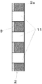
図1は、本発明によるオゾン水製造方法及びオゾン水製造装置に使用する電解セルの一態様を示す図面であり、1は、貫通する直径0.1mm以上の複数の貫通孔11を有する陽極、2は、該陽極1と同一部位に、貫通する直径0.1mm以上の複数の貫通孔11を有する陰極であり、3は、前記貫通孔11を持った陰極2の片面に陽イオン交換樹脂の分散液を塗布、焼成して形成した固体高分子電解質隔膜であり、前記陽極1、前記固体高分子電解質隔膜3及び前記陰極2を密着させて、膜−電極接合体8’が構成されている。陽極1は、オゾン発生用の陽極触媒を所定の形状と物性を持つ構造体に担持させたものであり、その前面に通電部材4が設けられており、陰極2は、水素発生用の陰極触媒を所定の形状と物性を持つ構造体に担持させたものであり、その前面に通電部材5が設けられ、電解セル8が構成されている。6及び7は、通電部材4及び5にそれぞれ接続された通電コードである。貫通孔11は、2個以上としその数は多い方がオゾン発生部位である陽極/固体高分子電解質隔膜界面の露出面積が増大し、好ましい。ただし、本発明の効果を十分に発揮させるためには、貫通孔11は、小さすぎると水の流路抵抗が増大するため、直径0.1mm以上とし、しかも、その数は可能な限り多数として水の円滑な流れを確保することが望ましい。貫通孔11の直径は、1〜5mmが好ましい。
Hereinafter, an embodiment of the present invention will be described with reference to FIG.
FIG. 1 is a view showing an embodiment of an electrolytic cell used in an ozone water production method and an ozone water production apparatus according to the present invention, wherein 1 is an anode having a plurality of through-
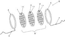
固体高分子電解質隔膜3は、前記貫通孔11を持った陽極1又は陰極2の少なくともいずれか一方の片面又は全面に陽イオン交換樹脂の分散液を塗布、焼成して形成したものである。図2−1、図2−2、図3−1、図3−2及び図4−1、図4−2は、それぞれ、前記陰極1の片面、前記陽極2の片面、及び前記陰極1の全面に陽イオン交換樹脂の分散液を塗布、焼成した電極およびそれを用いて構成した膜−電極接合体の断面図である。この3様態中では、前記陰極1の片面又は全面に陽イオン交換樹脂の分散液を塗布、焼成して固体高分子電解質隔膜3を形成することが好ましい。その理由としては、両極で発生する電解ガスの違いによるものであり、発生ガスは、固体高分子電解質隔膜3中の微小間隙等を通じて外部に拡散する必要があるが、陰極で発生する水素の方が、陽極で発生する酸素及びオゾンよりも圧倒的に分子サイズが小さく、拡散が容易である。そのため、図3−1、3−2に示すように、陽極1の表面に固体高分子電解質隔膜3をコーティングした場合、発生した酸素及びオゾンは、コーティングされた固体高分子電解質隔膜3を持ち上げ、固体電解質・電極間の密着性を劣化させ、本発明の効果が十分に発揮されないためである。1aは、陽極基材、1bは、ダイヤモンドコーテイング、2aは、陰極基材、2bは、陰極触媒である。ただし、本特許で使用される主要な陰極基材2aは、そのまま陰極触媒2bとしても作用させることができる。
The solid
更に、図4−1、4−2に示すように、膜−電極接合体8’の前記陰極全体に陽イオン交換樹脂の分散液を塗布、焼成して固体高分子電解質隔膜3を形成することが、更に好ましい。その理由は、陰極の片面のみにコーティングするよりも、陰極全体を覆うように陽イオン交換樹脂の分散液を塗布、焼成して、固体高分子電解質隔膜3を形成した方が電圧上昇が緩やかとなるため、寿命が飛躍的に向上する。その理由としては、陰極全体を固体電解質隔膜により覆うことにより、水酸化物の堆積が陽極との対向面、すなわち、電解反応面に集中せず、陰極全体に分散するからである。これは、電解後の堆積物観察より明らかである。更に、水酸化物が堆積しても、陰極の金属またはセラミックス面との間に存在する固体電解質隔膜により、水酸化物の堆積が反応面である金属またはセラミックス面すなわち陰極触媒表面を直接覆うことが無いため、陰極の水素発生反応が阻害されにくいと考えられる。具体的には、原料水中の微量のアルカリイオン例えばNa+は陰極表面に引き寄せられ、そこで陰極反応、Na++H2O+e-→NaOH+(1/2)H2によって陰極表面はアルカリ性となり、固体高分子電解質隔膜表面から滲みだして原料水中へ拡散する。このとき、イオン半径がNa+より大きい微量のアルカリ土類金属イオン例えばCa2+はNa+よりイオンの輸率としては小さいから、陰極表面に達する前に、固体高分子電解質隔膜表面近傍でアルカリ析出してCa(OH)2となる。この現象は膜−電極接合体の目視ないしは若干の拡大観察により、陰極の全面を固体高分子電解質隔膜で覆った場合には、陽極に対向する部分だけでなく、裏面も含めて陰極全面に同じように出現することが分かる。このように、陰極触媒表面それ自体は直接Ca(OH)2の析出層で覆われることがなくなり、電解は継続されることになる。ただし陰極表面で生成される水素分子の固体高分子電解質隔膜内の排出経路は次第に狭められることになるから、わずかながらも次第にセル電圧は上昇することになる。
Further, as shown in FIGS. 4-1 and 4-2, a dispersion of a cation exchange resin is applied to the entire cathode of the membrane-
本発明の上記の態様においては、前記貫通孔11を持った陽極1又は陰極2の少なくともいずれか一方の片面又は全面に前記貫通孔11を維持したままコーティングした固体高分子電解質隔膜3を形成するためには、前記貫通孔を持った陽極1又は陰極2の少なくともいずれか一方の片面又は全面に陽イオン交換樹脂の分散液を塗布、焼成しており、陽イオン交換樹脂の分散液として、陽イオン交換基としては、スルホン酸基、カルボン酸基、ホスホン酸基、リン酸基等を持った樹脂が挙げられるが、特にスルホン酸基を有し、化学安定性に優れるパーフルオロスルホン酸型陽イオン交換樹脂の分散液が好適である。いわゆるこのパーフルオロスルホン酸型陽イオン交換樹脂は完全には溶媒に溶けず、溶媒中で直径10nm前後の比較的大きなコロイドとして凝集していると考えられている。
イオン交換樹脂膜の形成工程は、先ず前述した電極基材上にこの分散液をスプレー、ローラー、刷毛、スポンジ等により塗布し、室温で所定の時間静置して溶媒の乾燥を行う。このとき分散液をノズル及びチップから滴下したまま放置し、平準化は分散液の拡張濡れに任すこともできる。さらに乾燥塗膜化した分散液−電極基材を120〜350℃に加熱する。加熱は乾燥器やマッフル炉やヒーティングガンを用いてもよく、ホットプレート上で行なってもよい。加熱温度は溶媒を蒸発するのみではなく、凝集コロイドを焼結させる必要があるが、あまりに高いと高分子が変質する恐れもあるので、150〜250℃程度が好ましい。このとき前述の微小間隙が形成されるものと考えられる。
電極基材上にあらかじめフッ素樹脂メッシュを置いたり、分散液にフッ素樹脂の架橋剤やフッ素樹脂フィラーを含有させておくと、加熱処理後に、補強された被膜を得ることができる。その他プロトン導電性の物質を利用して機械的強度を向上させる方法もある。
前記貫通孔を持った陽極1又は陰極2の少なくともいずれか一方の片面又は全面に前記貫通孔11を維持したままコーティングした固体高分子電解質隔膜3を形成するための他の方法としては、イオン交換樹脂の粉体により電極表面を被覆し、その後、加熱して半溶融状態で皮膜を形成する粉体コーティング法もある。
In the above aspect of the present invention, the solid
In the ion exchange resin film forming step, first, the dispersion is applied onto the above-described electrode substrate by spraying, rollers, brushes, sponges, etc., and left at room temperature for a predetermined time to dry the solvent. At this time, the dispersion can be left as it is dropped from the nozzle and the tip, and the leveling can be left to extended wetting of the dispersion. Further, the dispersion-electrode base material formed into a dry coating film is heated to 120 to 350 ° C. Heating may be performed using a dryer, a muffle furnace, a heating gun, or on a hot plate. The heating temperature is not only to evaporate the solvent, but it is necessary to sinter the agglomerated colloid, but if it is too high, the polymer may be denatured, so about 150 to 250 ° C. is preferable. At this time, the above-mentioned minute gap is considered to be formed.
When a fluororesin mesh is previously placed on the electrode substrate, or a fluororesin crosslinking agent or fluororesin filler is contained in the dispersion, a reinforced film can be obtained after the heat treatment. In addition, there is a method of improving the mechanical strength using a proton conductive substance.
As another method for forming the solid
図5−1及び図5−2は、本発明によるオゾン水製造方法及びオゾン水製造装置の一態様を示す図面であり、電解セル8には、通常電解用直流電源が接続されている。9は、陽極1の前面に設けられた陽極室、10は、陰極2の前面に設けられた陰極室、12は、電解セル8の陽極室9に原料水を供給するパイプ、13は、電解セル8の陰極室10より電解により生成するオゾン水を流出するパイプ、14は、電解セル8の陽極室9に原料水を供給する流入口、15は、電解セル8の陰極室10よりオゾン水を流出する流出口である。
FIGS. 5A and 5B are diagrams illustrating an embodiment of the ozone water manufacturing method and the ozone water manufacturing apparatus according to the present invention. The
図5−1及び図5−2においては、前記電解セル8を構成する前記陽極1及び前記陰極2の同一部位に、これらを貫通する直径0.1mm以上の複数の貫通孔11が2個以上設けられ、前記陽極1又は前記陰極2の少なくともいずれか一方の片面には、前記貫通孔11を維持したまま、前記固体高分子電解質隔膜3がコーティングされ、かつ、前記陽極室9に前記陽極1、前記固体高分子電解質隔膜3及び前記陰極2の表面に対して、これと直角方向又は斜め方向に原料水の流入口14、原料水供給用のパイプ12が接続され、前記陰極室10にこれと直角方向又は斜め方向にオゾン水の流出口15、オゾン水流出用のパイプ13が接続される。尚、前記固体高分子電解質隔膜3としては、前述の通り、前記陰極2の表面、裏面、貫通孔の全面を覆うように設けてもよい。
電解セル8としては、陽極室9、陰極室10、原料水の流入口14、オゾン水の流出口15は設けることなく、通電部材4、5を直接、原料水供給用のパイプ12、オゾン水流出用のパイプ13に接続してもよい。
また、前記電解セル8は、原料水の流れ方向に対して、直角方向ではなく、斜め方向に設けることもでき、斜め方向に設けた場合、電解面積が広くなり、オゾンの生成量を更に増加することができる。
In FIG. 5A and FIG. 5B, two or more through
As the
Further, the
原料水としては、純水、水道水又は少量の塩素又は次亜塩素酸塩を含有する水を使用することができる。原料水は、通常、陽極側より流入し、陰極側より電解により生成するオゾン水を流出させることが好ましい。しかるに、原料水として、純水を使用する場合には、上記に加えて、原料水としての純水を陰極側より流入し、陽極側より電解により生成するオゾン水を流出させることもできる。 As raw water, pure water, tap water, or water containing a small amount of chlorine or hypochlorite can be used. It is preferable that the raw material water normally flows in from the anode side and flows out ozone water generated by electrolysis from the cathode side. However, when pure water is used as the raw water, in addition to the above, pure water as the raw water can be introduced from the cathode side, and ozone water generated by electrolysis can be caused to flow out from the anode side.
前記電解セル8は、膜−電極接合体8’を複数段重ねてスタック構造とした電解セルを用いることができる。即ち、陽極/固体高分子電解質隔膜/陰極を単位とする要素体を2段重ねとし、上記と同様に電解セルを構成すると、オゾン濃度及び電流効率を向上することができる。膜−電極接合体8’を2段とすることで必要な電解電圧は2倍強となるが、得られるオゾン水中のオゾン濃度を57〜67%高めることが出来る。なお、膜−電極接合体8’は薄い構造体のためそれらを複数重ねてもほぼ同一形状の電解セルを用いることができる。
As the
前記原料水として微量のアルカリ金属イオンまたはアルカリ土類金属イオンを含む水、例えば水道水を用いる場合には、原料水の水流を陽極側から陰極方向に流すよう、前記陽極室9に前記陽極1、前記固体高分子電解質隔膜3及び前記陰極2の表面に対して、これと直角方向又は斜め方向に原料水の流入口14、原料水供給用のパイプ12を接続し、前記陰極室10にこれと直角方向又は斜め方向に電解により生成するオゾン水の流出口15、オゾン水流出用のパイプ13を接続し、原料水を陽極側より陰極側に通過させることが必要である。これにより陰極2及び固体高分子電解質隔膜3に水酸化析出物が堆積することを抑制することができる。
When water containing a small amount of alkali metal ions or alkaline earth metal ions, for example, tap water, is used as the raw water, the
図6は、本発明の更に他の実施態様を示すものであって、前記電解セル8に通電コード6、7を接続するとともに、電解により生成するオゾン水の流出口15に直角方向又は斜め方向に対流誘導筒17を設け、前記電解セル8を処理タンク18内に投げ入れたものである。本装置によると、陰極2及び陽極1より発生する、水素、酸素及びオゾンガスに伴う自然対流により、前記電解セルを稼働することができるようになり、電動ポンプ等の動力機構を設ける必要が無くなり、装置を小型化することができる。
また、通電コード6、7を設ける代わりに、電解セル8に電池を組み込めば、更に、可搬性を向上させることができる。
FIG. 6 shows still another embodiment of the present invention, in which current-carrying
Further, if a battery is incorporated in the
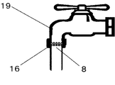
図7は、本発明の更に他の実施態様を示すものであって、前記電解セル8を上水道蛇口19あるいはそれに類する非精製水の排出口に取り付けたものである。本発明による電解セル8は、前記陽極室9及び前記陰極室10のいずれか一方より、前記陽極1、前記固体高分子電解質隔膜3及び前記陰極2の表面に対して、直角方向又は斜め方向に原料水を通過させてオゾン水を製造するので、本発明で用いる電解セル8は、流体配管の中間の長手方向にごく短い幅で配置することができるため流路圧力損失が抑えられ、且つ装置の小型化が可能である。
FIG. 7 shows still another embodiment of the present invention, in which the
電解セル8に使用する陽極1の陽極触媒としては、導電性ダイヤモンド電極が好ましい。貴金属及び貴金属酸化物電極に比較して、オゾン発生効率が高く、また二酸化鉛電極のような環境に及ぼす負荷がなく、停止時に放置しても活性が維持されるため、汎用性に優れているからである。
ダイヤモンドは、ドーピングにより電気伝導性の制御も可能であることから、電極材料として有望とされている。ダイヤモンド電極は非常に広い電位窓を持ち、酸素発生反応に対する活性化過電圧が大きく、酸化反応では酸素以外にオゾンの生成が報告されている(特開平11−269686号公報)。陽極基材としては処理水中で安定な不働態化被膜を形成するタンタル、ニオブ、チタン、ジルコニウム及びシリコン等の金属及びそれらの合金を用いれば、ダイヤモンド触媒は必ずしも陽極を完全に覆わなくともよく、前記基材の一部が露出していても大きな支障はない。代表的な熱フィラメントCVD法について以下に説明する。炭素源となるメタンCH4など炭化水素ガス、或いはアルコールなどの有機物を用い、CVDチャンバー内に水素ガスと共に送り込み、還元雰囲気に保ちながら、フィラメントを熱し、炭素ラジカルが生成する温度1800〜2400℃にする。このときダイヤモンドが析出する温度(750〜950℃)領域に電極基材を設置する。水素に対する炭化水素ガス濃度は0.1〜10vol%、圧力は20hPa〜1013hPa(1気圧)である。
As an anode catalyst for the
Diamond is considered promising as an electrode material because it can control electrical conductivity by doping. The diamond electrode has a very wide potential window, has a large activation overvoltage for the oxygen generation reaction, and ozone has been reported to be generated in addition to oxygen in the oxidation reaction (Japanese Patent Laid-Open No. 11-269686). If a metal such as tantalum, niobium, titanium, zirconium and silicon and their alloys are used as the anode base material that forms a stable passivation film in the treated water, the diamond catalyst does not necessarily completely cover the anode, Even if a part of the base material is exposed, there is no big trouble. A typical hot filament CVD method will be described below. Using a hydrocarbon gas such as methane CH 4 as a carbon source or an organic substance such as alcohol, it is sent together with hydrogen gas into the CVD chamber, and while maintaining a reducing atmosphere, the filament is heated to a temperature of 1800 to 2400 ° C. at which carbon radicals are generated To do. At this time, an electrode base material is installed in a temperature (750 to 950 ° C.) region where diamond is deposited. The hydrocarbon gas concentration with respect to hydrogen is 0.1 to 10 vol%, and the pressure is 20 hPa to 1013 hPa (1 atm).
ダイヤモンドが良好な導電性を得るために、原子価の異なる元素を微量添加することは不可欠である。ホウ素BやリンPの好ましい含有率は1〜100000ppmであり、更に好ましくは100〜10000ppmである。原料化合物にはトリメチルボロン(CH3)3Bを用いるが、毒性の少ない酸化ホウ素B2O3、五酸化二燐P2O5などの利用も好ましい。電極基材の形状としては、板のみならず、粒子、繊維、棒及び本発明で用いたような穴明き板などが可能である。 In order for diamond to obtain good conductivity, it is indispensable to add a trace amount of elements having different valences. The preferred content of boron B or phosphorus P is 1 to 100,000 ppm, more preferably 100 to 10,000 ppm. Trimethylboron (CH 3 ) 3 B is used as the raw material compound, but use of boron oxide B 2 O 3 , diphosphorus pentoxide P 2 O 5, etc., which is less toxic, is also preferable. As the shape of the electrode substrate, not only a plate but also particles, fibers, rods, a perforated plate used in the present invention, and the like are possible.
電解セル8に使用する陰極2の陰極反応は主に水素発生であり、水素に対して脆化しない電極触媒が好ましく、白金族金属、ニッケル、ステンレス、チタン、ジルコニウム、モリブデン、タングステン、シリコン、金、銀、カーボン、ダイヤモンド、各種金属炭化物などが好ましい。陰極2の陰極基材としてはステンレスの他、ジルコニウム、カーボン、ニッケル、チタン、モリブデン、タングステン、シリコン及びそれらの炭化物などに限定される。本発明の装置では、いずれもオゾン等の酸化性物質の溶解した水と接触する配置となるため、酸化耐性に優れたものが好ましく、またステンレスやニッケル等電極基材は、そのまま電極触媒として使用することができる。
The cathode reaction of the
また、陽極触媒として、導電性ダイヤモンド、無定型カーボン、グラファイト、二酸化鉛、貴金属および貴金属酸化物を反応触媒活性等の観点から適宜選択して、電極を入れ替えるだけで、有機電解合成、ダイオキシンを含む有機塩素化合物の分解、廃液処理、開発途上国における河川水の飲料水化、オゾン水製造等の用途に対応させることができる。 In addition, as the anode catalyst, conductive diamond, amorphous carbon, graphite, lead dioxide, noble metal and noble metal oxide are appropriately selected from the viewpoint of reaction catalyst activity, etc., and organic electrosynthesis and dioxin are included simply by replacing the electrode. It can be used for applications such as decomposition of organochlorine compounds, waste liquid treatment, river water drinking in developing countries, and ozone water production.
更に、本発明による殺菌方法においては、原料水として、純水又は水道水等を用いて、本発明による電解セルによりオゾン水を製造した後、製造されたオゾン水を用いて、被処理液を殺菌する。 Furthermore, in the sterilization method according to the present invention, pure water or tap water is used as raw water, and after the ozone water is produced by the electrolytic cell according to the present invention, the liquid to be treated is produced using the produced ozone water. Sterilize.
また、本発明による他の殺菌方法としては、原料水として、純水又は水道水等の代わりに、直接、殺菌に適用する被処理液を電解液として、本発明による電解セルに供給し、該被処理液を直接電解し、被処理液を殺菌してもよい。 Further, as another sterilization method according to the present invention, as a raw material water, instead of pure water or tap water, etc., a liquid to be treated to be directly applied to sterilization is supplied as an electrolytic solution to the electrolytic cell according to the present invention, The liquid to be treated may be directly electrolyzed to sterilize the liquid to be treated.
更に、本発明による廃水・廃液処理法においては、原料水として、純水又は水道水等を用いて、本発明による電解セルによりオゾン水を製造した後、製造されたオゾン水を用いて、廃水・廃液を処理する。 Furthermore, in the waste water / waste liquid treatment method according to the present invention, pure water or tap water is used as raw water, and after ozone water is produced by the electrolytic cell according to the present invention, waste water is produced using the produced ozone water.・ Process the waste liquid.
また、本発明による他の廃水・廃液処理法としては、原料水として、純水又は水道水等の代わりに、直接、被処理液である廃水・廃液を電解液として、本発明による電解セルに供給し、該廃水・廃液を直接電解し、廃水・廃液を処理してもよい。 In addition, as another waste water / waste liquid treatment method according to the present invention, instead of pure water or tap water as raw material water, the waste water / waste liquid which is the liquid to be treated is directly used as an electrolytic solution in the electrolytic cell according to the present invention. The waste water / waste liquid may be directly electrolyzed to treat the waste water / waste liquid.
次に本発明の実施例を説明するが、本発明はこれらに限定されるものではない。 Next, examples of the present invention will be described, but the present invention is not limited thereto.
<実施例1、実施例2、参考例1、比較例1>−純水電解−
実施例1として、図1に示す電解セル8、図2−1、2−2に示した膜−電極接合体、図5−1、図5−2に示すオゾン水製造装置を次のようにして製作した。
直径25mm厚さ3mmのニオブ板に直径3mmの孔を図1の配置で31個設けた基材にボロンドープダイヤモンド(BDD)を約9.6g/m2単位面積重量でコーティングし陽極とした。また、SUS304の板材を陽極と同一形状に加工し陰極とした。さらに、陰極の片面には、市販の陽イオン交換樹脂5%分散液(商品名:ナフィオンDE520、デュポン(株)の登録商標)を塗布し、200℃で焼成して固体高分子電解質隔膜被膜とし、前記陽極と組み合わせ、膜−電極接合体を構成した。この接合体を樹脂製の筐体に組み入れ電解セルとし、陽極及び陰極の両側に設けた純チタン製通電部材を通じ通電した。両電極と固体高分子電解質間の密着度合いは電解装置のオゾン生成特性に影響を与えるため、電解セルの一端に切られたM30のねじを5Nmのトルクで締め込むことで一定の圧力を確保した。このように構成した電解セルは、小型で且つ内部の被電解水の流路が直線的であり圧力損失が抑えられると同時に、既存配管への取り付けも容易である。
原料水としては20℃に保った純水(イオン交換水)を用い上記電解セルに一定流量を陽極側から導入した。また、直流定電流装置を用いて装置に一定電流を通電し、電圧計により電極間電圧(セル電圧)をモニターした。設定した原料水の流量及び電流値は表1中に示す。電解により生成したオゾン水中のオゾン濃度は、電解開始後5分以上経過して条件が安定した時点で電解セル出口水を一定量採取し、日本オゾン協会の暫定規格「オゾン濃度測定方法(平成6年3月刊)」に準拠し、硫酸酸性、ヨウ素・チオ硫酸ナトリウム滴定法により測定した。電解試験は、電流値を1.67Aとし、流水量を毎分170mlに設定して行った。
実施例2として、実施例1と同一のセルを用い、電解試験を、電流値を3.34Aとし流水量を毎分320mlに設定して行った。
生成されるオゾン水中のオゾン濃度は、オゾン水としての殺菌作用や洗浄作用の効果を左右するパラメーターであり、その用途により異なる一定範囲内の濃度で有ることが求められるが、そのような用途要求濃度より生成オゾン水中の濃度が高い場合には、流水量を増やすなどにより容易に調整が可能であるため、一般に装置能力としての生成オゾン濃度は高い方が好ましいとされる。
<Example 1, Example 2, Reference Example 1, Comparative Example 1> -Pure water electrolysis-
As Example 1, the
Boron-doped diamond (BDD) was coated at about 9.6 g / m 2 unit area weight on a base material in which 31 holes having a diameter of 3 mm were provided in the arrangement of FIG. 1 on a niobium plate having a diameter of 25 mm and a thickness of 3 mm, thereby forming an anode. Also, a SUS304 plate material was processed into the same shape as the anode to form a cathode. Furthermore, a commercially available
As raw material water, pure water (ion exchange water) kept at 20 ° C. was used, and a constant flow rate was introduced into the electrolysis cell from the anode side. In addition, a constant current was passed through the device using a DC constant current device, and the voltage between electrodes (cell voltage) was monitored with a voltmeter. The set raw material water flow rate and current value are shown in Table 1. The ozone concentration in the ozone water generated by electrolysis was collected for a certain amount of water at the outlet of the electrolysis cell when the conditions became stable after 5 minutes from the start of electrolysis. In accordance with "March year published)", it was measured by sulfuric acid acidity and iodine / sodium thiosulfate titration method. The electrolysis test was performed with the current value set to 1.67 A and the amount of flowing water set to 170 ml per minute.
As Example 2, the same cell as in Example 1 was used, and the electrolysis test was performed with a current value of 3.34 A and a flowing water amount of 320 ml per minute.
The ozone concentration in the generated ozone water is a parameter that determines the effect of the bactericidal action and cleaning action as ozone water, and it is required to have a concentration within a certain range that varies depending on the application. When the concentration of the generated ozone water is higher than the concentration, it can be easily adjusted by increasing the amount of running water. Therefore, it is generally preferable that the generated ozone concentration as the apparatus capacity is higher.
参考例1として、図8に示した電解セル8を次のようにして製作した。
直径25mm厚さ3mmのニオブ板に直径3mmの貫通孔11を31個設けた基材にボロンドープダイヤモンド(BDD)を約9.6g/m2単位面積重量でコーティングした陽極1とSUS304の板材を陽極1と同一形状に加工し両面をエミリー紙で1000番まで研磨した陰極2を用い、陽極1/陰極2間には、市販のパーフルオロスルホン酸型陽イオン交換膜(商品名:ナフィオン350、デュポン(株)の登録商標)を直径25mmに切り出し電極と同様に直径3mmの貫通孔11を計31個空けた固体高分子電解質隔膜3を挟み、膜−電極接合体8’を作成した。この膜−電極接合体8’を樹脂製の筐体に組み入れ、陽極1及び陰極2の両側に純チタン製通電部材4、5及び通電コード6、7を設け、電解セル8通じ通電し、実施例1と同様に純水を用いたオゾン水製造試験を実施した。
As Reference Example 1, the
An
比較例1として、図9−1に示す膜−電極接合体20’、図9−2に示すオゾン水製造装置を次のようにして製作した。即ち、実施例1及び実施例2と同様に貫通孔を設けた陽極21及び陰極22の間に、孔加工を行っていない市販のパーフルオロスルホン酸型陽イオン交換膜(商品名:ナフィオン350、デュポン(株)の登録商標)より成る固体高分子電解質隔膜23を挟み込み、樹脂製M2ねじ24で固定して膜−電極接合体20’を構成し、これに通電リング25を接続し、電解セル20とし、長手方向に拡大した電解セル20の内部に原料水が電極面に平行に流れるように配置したオゾン水製造装置を用い実施例1と同様に純水を原料水としたオゾン水生成試験を実施した。
実施例1、実施例2、参考例1、比較例1の結果を表1に示す。
As Comparative Example 1, a membrane-
The results of Example 1, Example 2, Reference Example 1, and Comparative Example 1 are shown in Table 1.

表1から明らかなように、実施例1及び実施例2では、本発明による電解セルによるオゾン水生成効率が、固体高分子電解質隔膜として既成の陽イオン交換膜を用いた以外は本発明と同一構成の電解セルを用いた参考例1、および従来構成の電解セルによる比較例1と比較し、セル電圧が顕著に低く電流効率及び生成オゾン水中のオゾン濃度も同等以上であることが、明らかとなった。
また、電解によるオゾン水製造装置の性能は、一般に、生成したオゾン水中のオゾン濃度あるいは電流効率により評価されるが、環境負荷の低減あるいはバッテリー駆動の可搬式装置設計の観点からは、電流効率ではなく、消費される電力効率により比較することが有意義であろう。その目的で、表1中に電力効率も併せて記載した。表1より、本発明による電解セルの電力効率の高さが顕著であることが分かる。なお、実施例2の消費電力量が高いのは、水の流量が毎分320mlと、実施例1、比較例1、及び参考例1の2倍であり、単位時間あたり倍のオゾン水を製造したためである。
As is clear from Table 1, in Examples 1 and 2, the ozone water generation efficiency by the electrolytic cell according to the present invention is the same as that of the present invention except that an existing cation exchange membrane is used as the solid polymer electrolyte membrane. It is clear that the cell voltage is remarkably low and the current efficiency and the ozone concentration in the generated ozone water are equal to or higher than those in Reference Example 1 using the electrolytic cell having the configuration and Comparative Example 1 using the electrolytic cell having the conventional configuration became.
In addition, the performance of ozone water production equipment by electrolysis is generally evaluated by the ozone concentration or current efficiency in the generated ozone water. From the viewpoint of reducing environmental impact or designing a battery-driven portable device, current efficiency is It would be meaningful to compare by the power efficiency consumed. For this purpose, the power efficiency is also shown in Table 1. Table 1 shows that the power efficiency of the electrolytic cell according to the present invention is remarkable. In addition, the amount of power consumption of Example 2 is high, the flow rate of water is 320 ml per minute, twice that of Example 1, Comparative Example 1, and Reference Example 1, and doubles ozone water per unit time is produced. Because.
<実施例3、実施例4、参考例2、比較例2>−水道水電解−
次に、原料水として純水の代わりに水道水を用いた場合の実施例、参考例及び比較例を実施例3〜4、参考例2及び比較例2として示す。
実施例3〜4として、先ず、オゾン水製造装置を次のようにして製作した。実施例1及び実施例2に記載の方法でニオブ板を加工しボロンドープダイヤモンドのコーティングを行ない陽極とした。また、SUS304の板材を陽極と同一形状に加工し陰極とした。実施例3では、図3−1、3−2に示すように、陽極の片面に市販の陽イオン交換樹脂5%分散液(商品名:ナフィオンDE520、デュポン(株)の登録商標)を塗布し、200℃で焼成して固体高分子電解質隔膜とし、前記陰極と組み合わせ、膜−電極接合体を構成した。
また、実施例4では、図2−1、2−2に示すように、陰極の片面に同様に陽イオン交換樹脂をコーティングし、前記ボロンドープダイヤモンドをコーティングした陽極と組み合わせ、膜−電極接合体を実施例1〜2と同一構成とした。これらの膜−電極接合体を実施例1〜2と同様に樹脂製の電解セルに組み入れ電解セルとし、陽極及び陰極の両側に設けた純チタン製通電部材を通じ通電した。原料水として一般上水道水を用い、流量及び電解電流をそれぞれ、毎分170ml、0.5Aとし、200時間の連続電解試験により、主にCaなど水道中に微量に含まれるアルカリ土類金属イオンが水酸化物として堆積する程度を調べた。また、電解時における陽極/陰極間の電圧を電解電圧としてモニターし、5分間隔で自動記録した。
<Example 3, Example 4, Reference Example 2, Comparative Example 2> -Tap water electrolysis-
Next, Examples, Reference Examples and Comparative Examples in which tap water is used instead of pure water as raw water will be shown as Examples 3 to 4, Reference Example 2 and Comparative Example 2.
As Examples 3 to 4, first, an ozone water production apparatus was produced as follows. The niobium plate was processed by the method described in Example 1 and Example 2 and coated with boron-doped diamond to form an anode. Also, a SUS304 plate material was processed into the same shape as the anode to form a cathode. In Example 3, as shown in FIGS. 3-1 and 3-2, a commercially available
Further, in Example 4, as shown in FIGS. 2-1 and 2-2, a cation exchange resin is similarly coated on one side of the cathode, and combined with the boron-doped diamond-coated anode. The same configuration as in Examples 1-2. These membrane-electrode assemblies were incorporated into a resin-made electrolytic cell in the same manner as in Examples 1 and 2 to form an electrolytic cell, and energized through a pure titanium current-carrying member provided on both sides of the anode and the cathode. General tap water is used as the raw water, the flow rate and the electrolysis current are 170 ml and 0.5 A per minute, respectively, and alkaline earth metal ions contained in trace amounts in the water such as Ca are mainly obtained by continuous electrolysis test for 200 hours. The degree of deposition as hydroxide was examined. In addition, the voltage between the anode and the cathode during electrolysis was monitored as the electrolysis voltage and recorded automatically at 5-minute intervals.
次に、参考例1と同一構成の電解セルを用い、水道水を原料として、実施例3〜4と同一電解条件でオゾン水製造実験を行い参考例2とした。 Next, using an electrolysis cell having the same configuration as that of Reference Example 1 and using tap water as a raw material, an ozone water production experiment was carried out under the same electrolysis conditions as in Examples 3 to 4 to obtain Reference Example 2.
更に、比較例1と同一構成の電解セルを用い、水道水を原料として同一条件でオゾン水製造実験を行い、比較例2とした。 Furthermore, using the electrolytic cell having the same configuration as that of Comparative Example 1 and using tap water as a raw material, an ozone water production experiment was conducted under the same conditions as Comparative Example 2.
<比較例3>
一般の水道水は微量のアルカリ金属イオン、アルカリ土類金属イオン、塩素イオン及び炭酸イオンなどを含むため若干の導電性を示す。そのため、固体高分子電解質隔膜を陽極/陰極間に設置せずに実施例1記載の貫通孔を設けた陽極と陰極を至近距離に設置することで、本発明と同様な効果が得られる可能性を検証した。比較例3では、実施例1及び実施例2記載のコーティングによる固体高分子電解質隔膜に換えて、直径25mmに加工した厚さ0.75mm、メッシュサイズLW6.6mm、SW4.4mmのポリエチレンメッシュをセパレーターとして陽/陰極間に設置し、水道水電解試験に供した。原料の水道水は、実施例3〜4と同様に両極に開けられた貫通孔を通じて陽極側から陰極側に流出する。ただし、固体高分子電解質隔膜を用いない本例では、実施例3〜4と同程度の電流を通電することは、電解電圧が電源の電圧能力の上限である30Vに達するため不可能であり、電解電流を0.1Aとした。
本明細書記載の他の水道水電解と同様、電解電圧は時間と共に上昇し約140時間で20Vに達した。その後、電解を継続したが、電源の電圧能力の上限である30Vに達した330時間を経過した時点で最終的に電解を中止した。
試験後の電解セルを分解して調べたところ、電流値は5分の1と少ないにもかかわらず、比較例2と同程度の水酸化物の堆積が確認された。
すなわち、本例より固体高分子電解質隔膜を用いないオゾン水製造は、極めて非効率であることが明らかである。
<Comparative Example 3>
Since general tap water contains a trace amount of alkali metal ions, alkaline earth metal ions, chlorine ions, carbonate ions, etc., it shows some conductivity. Therefore, the same effect as that of the present invention can be obtained by installing the anode and the cathode provided with the through hole described in Example 1 at a close distance without installing the solid polymer electrolyte membrane between the anode and the cathode. Verified. In Comparative Example 3, a polyethylene mesh having a thickness of 0.75 mm, a mesh size LW of 6.6 mm, and a SW of 4.4 mm processed to a diameter of 25 mm was used instead of the solid polymer electrolyte membrane with the coating described in Example 1 and Example 2. And installed between the positive and negative electrodes for a water electrolysis test. The raw tap water flows out from the anode side to the cathode side through through-holes opened in both electrodes as in Examples 3-4. However, in this example not using a solid polymer electrolyte membrane, it is impossible to pass a current of the same level as in Examples 3 to 4 because the electrolytic voltage reaches 30 V, which is the upper limit of the voltage capability of the power source. The electrolysis current was 0.1A.
As with the other tap water electrolysis described herein, the electrolysis voltage increased with time and reached 20 V in about 140 hours. Thereafter, the electrolysis was continued, but the electrolysis was finally stopped at the time when 330 hours had passed when the voltage capability of the power source reached 30 V.
When the electrolytic cell after the test was disassembled and examined, the same amount of hydroxide deposition as in Comparative Example 2 was confirmed although the current value was as low as 1/5.
That is, it is clear from this example that ozone water production without using a solid polymer electrolyte membrane is extremely inefficient.
実施例3、実施例4、参考例2、比較例2、比較例3の結果を表2に示す。また、実施例3、実施例4、参考例2、比較例2の電圧の経時変化を図10に示す。 Table 2 shows the results of Example 3, Example 4, Reference Example 2, Comparative Example 2, and Comparative Example 3. In addition, FIG. 10 shows changes over time in the voltages of Example 3, Example 4, Reference Example 2, and Comparative Example 2.
表2から明らかなように、連続電解を200時間行った後に電解セルを分解し、水酸化物の堆積状態を目視により調べた結果、比較例2では陰極全面に厚い堆積が認められたのに対し、実施例3、実施例4、及び参考例2では、堆積量はほぼ同程度で比較的軽度であった。
一方、電解電圧は水酸化物の堆積に伴い徐々に増加するが、図10に示すように、その上昇の程度は膜−電極接合体の構成の違いにより、明確に異なった。比較例2では、電解電圧は、200時間で30Vに達したのに対し、参考例2、実施例3、実施例4の順にその上昇が緩やかであり、本提案の優位性が確認できる。特にカソード側に固体電解質をコーティングし膜−電極接合体を構成した実施例4では、アノード側に固体電解質をコーティングした実施例3と比較して電解電圧が安定しており、その上昇も極めて緩やかであった。これは、コーティングされた固体電解質は、構成する高分子間の間隙あるいは、分散液からのコーティングプロセス中に膜中に生じる無数の微小間隙等を通じたガス透過特性に関連しているものと推測される。すなわち、電解により発生する気体は、陰極側では水素であり、分子サイズが小さく容易に膜中を通過拡散できるのに対し、陽極側では、発生する酸素及びオゾンの分子サイズが大きいため膜透過性が低いことに起因し、陽極側では、発生した酸素ガス及び水中に溶け込むことの無かったオゾンガスが固体高分子電解質隔膜を持ち上げ、本発明のポイントである固体高分子電解質隔膜・電極間の密着性を劣化させるため、結果的に膜−電極接合体が既存の固体高分子電解質隔膜を用いた構成に近づき、本発明の効果が十分に発揮されないものと考えられる。また逆に、ガスによる固体電解質の密着性劣化が発生しない場合には、陽極を全面的に覆った固体高分子電解質隔膜により、原料である水の供給が制限され電解反応が律速されることも高電圧の要因となり得る。なお、一般に実用水電解では電解電圧がある一定値に達した時点を目安に酸洗等により堆積物を除去し機能を復活させるためのメンテナンス作業が行われるため、電解電圧の上昇が緩やかであることは、メンテナンス低減の観点から有益である。
As is apparent from Table 2, the electrolytic cell was disassembled after 200 hours of continuous electrolysis, and the deposition state of hydroxide was visually examined. As a result, in Comparative Example 2, thick deposition was observed on the entire cathode surface. On the other hand, in Example 3, Example 4, and Reference Example 2, the deposition amount was almost the same and relatively light.
On the other hand, the electrolytic voltage gradually increased with the deposition of hydroxide, but as shown in FIG. 10, the degree of increase was clearly different depending on the configuration of the membrane-electrode assembly. In Comparative Example 2, the electrolytic voltage reached 30 V in 200 hours, whereas the increase was moderate in the order of Reference Example 2, Example 3, and Example 4, and the superiority of the present proposal can be confirmed. In particular, in Example 4 in which a solid electrolyte was coated on the cathode side to form a membrane-electrode assembly, the electrolysis voltage was more stable than in Example 3 in which the solid electrolyte was coated on the anode side. Met. This is presumed that the coated solid electrolyte is related to gas permeation characteristics through gaps between the constituting polymers or innumerable minute gaps generated in the membrane during the coating process from the dispersion. The In other words, the gas generated by electrolysis is hydrogen on the cathode side and has a small molecular size and can easily pass and diffuse through the membrane, whereas on the anode side, the generated oxygen and ozone have a large molecular size, so the membrane permeability is high. In the anode side, the generated oxygen gas and the ozone gas that did not dissolve in the water lift the solid polymer electrolyte membrane, and the adhesion between the polymer electrolyte membrane and the electrode, which is the point of the present invention. As a result, the membrane-electrode assembly approaches the configuration using the existing solid polymer electrolyte membrane, and the effect of the present invention is not sufficiently exhibited. Conversely, if the solid electrolyte adhesion deterioration due to gas does not occur, the supply of water as a raw material is limited by the solid polymer electrolyte membrane covering the anode entirely, and the electrolytic reaction may be controlled. It can cause high voltage. In general, in practical water electrolysis, since the maintenance work is performed to restore the function by removing deposits by pickling, etc., when the electrolysis voltage reaches a certain value, the increase in electrolysis voltage is slow. This is beneficial from the viewpoint of reducing maintenance.
<実施例5、実施例6、参考例3、比較例4>−水道水電解−
オゾン水製造効率の向上を目的として、水道水を原料とした高電流密度電解を行った。先ず、陽極用ニオブ板材及び陰極用SUS304板材を実施例1〜2と同様に加工し、陰極には実施例1、2、4記載の固体電解質をコーティングした。その際、固体電解質コーティングを片面に施した陰極による膜−電極接合体を用いた電解セル(実施例1、2、4と同一構成)による電解試験を実施例5とし、図4−1、4−2に示すように、通電部を除いた全露出表面、すなわち陽極との対向面、その裏面及び貫通孔壁面を固体高分子電解質隔膜のコーティングで覆った陰極による膜−電極接合体を用いた電解セルによる電解試験を実施例6とした。電流は、2.0Aとし、水流量は、毎分170mlとした。その他の電解試験実施要領は、実施例3及び実施例4と同一である。
また、参考例3として、参考例1と同一構成の電解セルを用い、水道水を原料として、実施例5〜6と同一電解条件でオゾン水製造実験を行い参考例3とした。
さらに、比較例1と同一構成の電解セルを用い、水道水を原料として実施例5〜6と同一条件でオゾン水製造実験を行い、比較例4とした。電解開始後のオゾン濃度は、実施例1〜2記載の方法により測定した。ただし、本実施例では、原料水中に微量に含まれる塩素イオンから生成される次亜塩素酸などオゾン以外の酸化性物質も生じるため、実施例1〜2記載のヨウ素法ではオゾンにそれらを加えた酸化性物質の総酸化等量が求められる。
実施例5、実施例6、参考例3、比較例4の結果を表3に示す。また、電圧の経時変化を図11に示す。
<Example 5, Example 6, Reference Example 3, Comparative Example 4> -Tap water electrolysis-
For the purpose of improving ozone water production efficiency, high current density electrolysis using tap water as a raw material was performed. First, the niobium plate material for anode and the SUS304 plate material for cathode were processed in the same manner as in Examples 1 and 2, and the cathode was coated with the solid electrolyte described in Examples 1, 2, and 4. At that time, an electrolytic test using an electrolytic cell (same configuration as in Examples 1, 2, and 4) using a cathode-membrane membrane-electrode assembly having a solid electrolyte coating on one side is referred to as Example 5, and FIGS. As shown in Fig.-2, a membrane-electrode assembly using a cathode in which the entire exposed surface excluding the current-carrying portion, that is, the surface facing the anode, the back surface thereof, and the wall surface of the through hole were covered with a coating of a solid polymer electrolyte membrane was used. An electrolysis test using an electrolysis cell was taken as Example 6. The current was 2.0 A and the water flow rate was 170 ml per minute. Other electrolytic test implementation procedures are the same as those in Example 3 and Example 4.
In addition, as Reference Example 3, an electrolytic cell having the same configuration as in Reference Example 1 was used, and tap water was used as a raw material, and an ozone water production experiment was performed under the same electrolysis conditions as in Examples 5 to 6, and Reference Example 3 was obtained.
Furthermore, using an electrolytic cell having the same configuration as that of Comparative Example 1 and using tap water as a raw material, an ozone water production experiment was performed under the same conditions as in Examples 5 to 6, and Comparative Example 4 was obtained. The ozone concentration after the start of electrolysis was measured by the method described in Examples 1-2. However, in this example, oxidizing substances other than ozone such as hypochlorous acid generated from chlorine ions contained in a trace amount in the raw material water are also generated. Therefore, in the iodine method described in Examples 1 and 2, they are added to ozone. The total oxidation equivalent of the oxidizing material is required.
The results of Example 5, Example 6, Reference Example 3, and Comparative Example 4 are shown in Table 3. In addition, FIG. 11 shows changes with time in voltage.
表3及び図11から明らかなように、参考例3及び比較例4の電解試験では、何れも電解電圧が早期に上昇し、先ず比較例4、次いで参考例3が順次20Vを超えたため、5時間で電解を中止した。また、実施例5及び実施例6では電圧上昇が穏やかであったため、それぞれ電圧が20Vに達した59時間及び122時間の時点で電解を中止した。以上の結果より、水道水のような微量アルカリ及びアルカリ土類イオンを含む原料水を用いたオゾン水製造用装置の場合、メンテナンスなしで操業できる稼働時間は、実施例6>実施例5>>参考例3>比較例4の順で長い。すなわち、本提案による膜−電極接合体を用いた電解セルは、従来の電解セルと比較し顕著に優れており、また、本提案による実施例間の比較からは、陰極全体を固体電解質で覆うことでさらに優れた性能が発揮されることがわかる。
なお、実施例5及び実施例6において測定されたオゾン濃度換算の酸化性物質量は、参考例3と同等で、比較例4を上回った。
As apparent from Table 3 and FIG. 11, in the electrolysis tests of Reference Example 3 and Comparative Example 4, the electrolysis voltage rose early, first Comparative Example 4 and then Reference Example 3 exceeded 20 V in order. The electrolysis was stopped over time. Moreover, in Example 5 and Example 6, since the voltage increase was moderate, electrolysis was stopped at 59 and 122 hours when the voltage reached 20 V, respectively. From the above results, in the case of an apparatus for producing ozone water using raw water containing trace amounts of alkali and alkaline earth ions such as tap water, the operating time that can be operated without maintenance is as follows: Example 6> Example 5 >> Reference Example 3> Longer in the order of Comparative Example 4. That is, the electrolysis cell using the membrane-electrode assembly according to the present proposal is remarkably superior to the conventional electrolysis cell, and from the comparison between the examples according to the present proposal, the entire cathode is covered with a solid electrolyte. It can be seen that even better performance is exhibited.
In addition, the amount of oxidizing substances in terms of ozone concentration measured in Example 5 and Example 6 was equivalent to Reference Example 3 and exceeded that of Comparative Example 4.
<実施例7、実施例8、比較例5>−廃水処理(脱色効果の確認)−
実施例7として、固体高分子電解質隔膜被膜を陰極の片面に形成した実施例5に記載の膜−電極接合体及び電解セルを用いて、以下の通り廃水処理試験を行った。また、実施例8として、固体高分子電解質隔膜被膜を陰極の全面に形成した実施例6に記載の膜−電極接合体及び電解セルを用いて、以下の通り廃水処理試験を行った。
原料水としては、純水(イオン交換水)に赤色の染色原料であるアマランスを被処理物質として100ppm添加した溶液を用いた。本実施例で用いたダイヤモンド陽極は、環境ホルモンや農薬等の多数の化合物が分解できるため被処理物質はこれに限定されるものではない。
原料水500mlを上部開放の三角フラスコに入れて20℃に保ち、上記電解セルに毎分70mlで陽極側から導入し、陰極側から排出させ、さらに三角フラスコに還流させた。また、直流定電流装置を用いて電解セルに2.0Aを通電した。
電解開始後、初期及び0.5時間、1.0時間、1.5時間経過時において、上記三角フラスコ中から液を5mlずつ採取し、300〜700nmの波長範囲で紫外可視分光光度計(型番UV−2500PC、(株)島津製作所製)による測定を行った。アマランスの0.5時間経過時における吸収スペクトルを図12に示した。吸光度が小さいほどアマランス濃度も小さい。
波長521nm付近の吸収スペクトルを用い、初期の原料液の吸光度から検量線を作成して、0.5時間経過時のアマランス濃度を定量したところ、その濃度は固体高分子電解質隔膜被膜をSUS304陰極の片面に施した実施例7の膜−電極接合体が8.0ppm、全面に施した実施例8の膜−電極接合体は9.3ppmであった。
実施例7及び8の膜−電極接合体は、いずれもアマランス濃度は時間が経過するごとに低下して、1.5時間経過時にはほとんど脱色され、その濃度はいずれも0.3ppmであった。分解生成物を分析したところ、アマランスの分解生成物であるCO3 -、シュウ酸等の低分子量化合物が生成していることが確認された。
<Example 7, Example 8, Comparative Example 5> -Waste water treatment (confirmation of decoloring effect)-
As Example 7, a wastewater treatment test was performed as follows using the membrane-electrode assembly and the electrolytic cell described in Example 5 in which a solid polymer electrolyte membrane film was formed on one side of the cathode. Further, as Example 8, a wastewater treatment test was performed as follows using the membrane-electrode assembly and the electrolytic cell described in Example 6 in which a solid polymer electrolyte membrane film was formed on the entire surface of the cathode.
As the raw material water, a solution in which 100 ppm of amaranth, which is a red dyeing raw material, was added to pure water (ion exchange water) as a material to be treated was used. Since the diamond anode used in this example can decompose many compounds such as environmental hormones and agricultural chemicals, the material to be treated is not limited to this.
500 ml of raw material water was placed in an open top Erlenmeyer flask and kept at 20 ° C., introduced into the electrolytic cell at 70 ml / min from the anode side, discharged from the cathode side, and further refluxed to the Erlenmeyer flask. Moreover, 2.0 A was supplied to the electrolysis cell using a direct current constant current device.
After the start of electrolysis, 5 ml of the liquid was sampled from the Erlenmeyer flask at the initial stage and 0.5 hour, 1.0 hour, and 1.5 hour, and an ultraviolet-visible spectrophotometer (model number) was used in the wavelength range of 300 to 700 nm. Measurement was performed using UV-2500PC (manufactured by Shimadzu Corporation). The absorption spectrum of amaranth after 0.5 hours is shown in FIG. The smaller the absorbance, the smaller the amaranth concentration.
Using an absorption spectrum near a wavelength of 521 nm, a calibration curve was created from the absorbance of the initial raw material solution, and the amaranth concentration after 0.5 hours was quantified. The concentration was determined by applying the solid polymer electrolyte membrane coating to the SUS304 cathode. The membrane-electrode assembly of Example 7 applied to one side was 8.0 ppm, and the membrane-electrode assembly of Example 8 applied to the entire surface was 9.3 ppm.
In each of the membrane-electrode assemblies of Examples 7 and 8, the amaranth concentration decreased with the passage of time, and was almost decolorized after the lapse of 1.5 hours, both of which were 0.3 ppm. Analysis of the decomposition products confirmed that low molecular weight compounds such as CO 3 − and oxalic acid, which are decomposition products of amaranth, were produced.
比較例5として、比較例1に記載の膜−電極接合体及び電解セルを用いたこと以外は、実施例7、実施例8に記載の原料水、電解方法及び測定方法を用いて実験を行った。アマランスの0.5時間経過時における吸収スペクトルを図12に示した。吸光度が小さいほどアマランス濃度も小さい。
0.5時間経過時のアマランス濃度を定量したところ、その濃度は10.9ppmであった。
アマランス濃度は時間が経過するごとに低下して、1.5時間経過時にはほとんど脱色され、その濃度は0.3ppmであった。分解生成物を分析したところ、アマランスの分解生成物であるCO3 -、シュウ酸等の低分子量化合物が生成していることが確認された。
図12から、実施例7及び実施例8のアマランス濃度の減少の速度が比較例5より大きいことは明らかである。なお、実施例8の濃度減少速度が実施例7と比較しやや劣るのは、固体高分子電解質隔膜により陰極の全面が覆われているため、陽極で生成したオゾンが陰極触媒に触れることにより発生し強い酸化力を持つOHフリーラジカルの生成が抑制されるためと考えられる。
As Comparative Example 5, an experiment was performed using the raw material water, electrolysis method, and measurement method described in Example 7 and Example 8, except that the membrane-electrode assembly and electrolytic cell described in Comparative Example 1 were used. It was. The absorption spectrum of amaranth after 0.5 hours is shown in FIG. The smaller the absorbance, the smaller the amaranth concentration.
When the amaranth concentration at the time of 0.5 hours was quantified, the concentration was 10.9 ppm.
The amaranth concentration decreased with the passage of time, and was almost decolorized after 1.5 hours. The concentration was 0.3 ppm. Analysis of the decomposition products confirmed that low molecular weight compounds such as CO 3 − and oxalic acid, which are decomposition products of amaranth, were produced.
From FIG. 12, it is clear that the rate of decrease in the amaranth concentration in Examples 7 and 8 is higher than that in Comparative Example 5. The concentration reduction rate of Example 8 is slightly inferior to that of Example 7 because the entire surface of the cathode is covered with the solid polymer electrolyte membrane, so that ozone generated at the anode touches the cathode catalyst. This is probably because the production of OH free radicals with strong oxidizing power is suppressed.
本発明の膜−電極接合体によれば、貫通孔を持った陽極1又は陰極2の少なくともいずれか一方の片面または全面に陽イオン交換樹脂の分散液を塗布、焼成して固体高分子電解質隔膜3としているので、装置の製作コストを著しく抑えることができるとともに、電解電圧が低下し、電力効率を飛躍的に向上させることができる。
本発明は、流体配管の中間の長手方向にごく短い幅で配置することができるため流路圧力損失が抑えられ、且つ装置の小型化が可能となるとともに、また、陽極、陰極及び固体高分子電解質隔膜から成る膜−電極接合体は、必要に応じ複数を重ねて電解セルを構成し、装置能力を容易に増大させることが可能であり、オゾン水製造能力を落とさずに装置のさらなる小型化が実現できる。そのため、一般上水道への後付による設置を前提とするような、小型装置の商品化設計が容易となるとともに、更に、水の入った容器に脱着の容易な可搬式電解セルを投入して電解を行う、いわゆる投げ込み型装置によるオゾン水製造電解にも適する。しかも、水の循環は、装置に組み合わせたポンプによってもよいが、入り口と出口をオープンとし原料水の流れ方向が重力方向に平行となる様に電解セルを設置しさらに装置の出口側に対流促進誘導筒を設けた構造として、電解によりオゾンガス以外に生成される酸素ガス及び水素ガスの上昇に伴う自然対流を利用することで、投げ込み型装置の構造が簡素化され実用上有益である。更に、本発明によるオゾン水製造方法及びオゾン水製造装置は、既存の技術と組み合わせると多くの用途に実用化の範囲を広げることができる。たとえば、オゾンは水中で容易に分解するため、オゾン濃度が時間と共に急速に低下するオゾン水の実用寿命を延長するために提案されたナノバブルオゾン水の製造装置は、本発明によるオゾン水製造装置の一部にたとえば超音波発生装置を組み込むことにより実現が可能である。この際、陰極あるいは陽極を超音波伝達板として利用すれば、装置サイズをあまり大きくせずに機能を追加できる。また、同様に安定したオゾン水を得る方法として、原料水中あるいは生成オゾン水中に炭酸ガスを溶解させる方法が提案されているが、本発明によるオゾン水製造方法及びオゾン水製造装置と組み合わせることが容易に可能となる。
また、本発明は、有機電解合成、ダイオキシンを含む有機塩素化合物の分解、廃液処理、開発途上国における河川水の飲料水化等の用途に対応させることができる。
According to the membrane-electrode assembly of the present invention, a dispersion of a cation exchange resin is applied to one surface or the entire surface of at least one of the
Since the present invention can be disposed with a very short width in the middle longitudinal direction of the fluid piping, the flow pressure loss can be suppressed, the apparatus can be downsized, and the anode, cathode and solid polymer Membrane-electrode assemblies consisting of electrolyte membranes can be stacked as needed to form an electrolytic cell, which can easily increase the capacity of the device, further reducing the size of the device without reducing the ozone water production capacity Can be realized. For this reason, it is easy to commercialize a small device that is premised on retrofitting to a general water supply, and in addition, a portable electrolytic cell that can be easily detached is put into a container containing water. It is also suitable for ozone water production electrolysis using a so-called throw-in type apparatus. Moreover, water circulation may be performed by a pump combined with the device, but an electrolytic cell is installed so that the inlet and outlet are open and the flow direction of the raw material water is parallel to the direction of gravity, and convection is further promoted on the outlet side of the device. By using natural convection associated with the rise of oxygen gas and hydrogen gas generated in addition to ozone gas by electrolysis as a structure provided with an induction cylinder, the structure of the throwing type apparatus is simplified and useful in practice. Furthermore, the ozone water production method and the ozone water production apparatus according to the present invention can expand the range of practical use for many applications when combined with existing technologies. For example, since ozone is easily decomposed in water, the nanobubble ozone water production apparatus proposed for extending the practical life of ozone water in which the ozone concentration rapidly decreases with time is the ozone water production apparatus according to the present invention. This can be realized by incorporating, for example, an ultrasonic generator in a part. At this time, if the cathode or the anode is used as an ultrasonic transmission plate, the function can be added without enlarging the apparatus size. Similarly, as a method of obtaining stable ozone water, a method of dissolving carbon dioxide gas in raw water or generated ozone water has been proposed, but it can be easily combined with the ozone water production method and ozone water production apparatus according to the present invention. It becomes possible.
In addition, the present invention can be applied to applications such as organic electrolytic synthesis, decomposition of organic chlorine compounds including dioxins, waste liquid treatment, and river water drinking in developing countries.
1:陽極
1a:陽極基材
1b:ダイヤモンドコーテイング
2:陰極
2a:陰極基材
3:固体高分子電解質隔膜
4、5:通電部材
6、7:通電コード
8:電解セル
8’:膜−電極接合体
9:陽極室
10:陰極室
11:貫通孔
12:原料水の流入パイプ
13:オゾン水の流出パイプ
14:流入口
15:流出口
16:面積制限リング
17:対流誘導筒
18:処理槽
19:水道蛇口
20:電解セル
20’:膜−電極接合体
21:陽極
22:陰極
23:固体高分子電解質隔膜
24:ねじ
25:通電部材
1:
Claims (16)
Priority Applications (8)
| Application Number | Priority Date | Filing Date | Title |
|---|---|---|---|
| JP2010197149A JP5113892B2 (en) | 2010-04-30 | 2010-09-02 | Membrane-electrode assembly, electrolytic cell using the same, ozone water production apparatus, ozone water production method, sterilization method, and waste water / waste liquid treatment method |
| PCT/JP2010/071769 WO2011135748A1 (en) | 2010-04-30 | 2010-11-29 | Membrane-electrode assembly, electrolytic cell using the same, method and apparatus for producing ozone water, method for disinfection and method for wastewater or waste fluid treatment |
| EP10795475.2A EP2563725B1 (en) | 2010-04-30 | 2010-11-29 | Membrane-electrode assembly, electrolytic cell using the same, method and apparatus for producing ozone water, method for disinfection and method for wastewater or waste fluid treatment |
| CA2797801A CA2797801C (en) | 2010-04-30 | 2010-11-29 | Membrane-electrode assembly, electrolytic cell using the same, method and apparatus for producing ozone water, method for disinfection and method for wastewater or waste fluid treatment |
| CN201080066521.7A CN102869616B (en) | 2010-04-30 | 2010-11-29 | Membrane-electrode assembly, electrolytic cell using the same, method and apparatus for producing ozone water, method for disinfection and method for wastewater or waste fluid treatment |
| US13/641,436 US20130032491A1 (en) | 2010-04-30 | 2010-11-29 | Membrane-electrode assembly, electrolytic cell using the same, method and apparatus for producing ozone water, method for disinfection and method for wastewater or waste fluid treatment |
| KR1020127031034A KR101450992B1 (en) | 2010-04-30 | 2010-11-29 | Membrane-electrode assembly, electrolytic cell using the same, method and apparatus for producing ozone water, method for disinfection and method for wastewater or waste fluid treatment |
| TW100115072A TWI472563B (en) | 2010-04-30 | 2011-04-29 | Membrane-electrode assembly, electrolytic cell using the same, method and apparatus for producing ozone water, method for disinfection and method for wastewater or waste fluid treatment |
Applications Claiming Priority (3)
| Application Number | Priority Date | Filing Date | Title |
|---|---|---|---|
| JP2010105752 | 2010-04-30 | ||
| JP2010105752 | 2010-04-30 | ||
| JP2010197149A JP5113892B2 (en) | 2010-04-30 | 2010-09-02 | Membrane-electrode assembly, electrolytic cell using the same, ozone water production apparatus, ozone water production method, sterilization method, and waste water / waste liquid treatment method |
Publications (3)
| Publication Number | Publication Date |
|---|---|
| JP2011246800A true JP2011246800A (en) | 2011-12-08 |
| JP2011246800A5 JP2011246800A5 (en) | 2012-03-08 |
| JP5113892B2 JP5113892B2 (en) | 2013-01-09 |
Family
ID=43728754
Family Applications (1)
| Application Number | Title | Priority Date | Filing Date |
|---|---|---|---|
| JP2010197149A Active JP5113892B2 (en) | 2010-04-30 | 2010-09-02 | Membrane-electrode assembly, electrolytic cell using the same, ozone water production apparatus, ozone water production method, sterilization method, and waste water / waste liquid treatment method |
Country Status (8)
| Country | Link |
|---|---|
| US (1) | US20130032491A1 (en) |
| EP (1) | EP2563725B1 (en) |
| JP (1) | JP5113892B2 (en) |
| KR (1) | KR101450992B1 (en) |
| CN (1) | CN102869616B (en) |
| CA (1) | CA2797801C (en) |
| TW (1) | TWI472563B (en) |
| WO (1) | WO2011135748A1 (en) |
Cited By (15)
| Publication number | Priority date | Publication date | Assignee | Title |
|---|---|---|---|---|
| KR20140018158A (en) * | 2012-08-03 | 2014-02-12 | 이정렬 | Water treatment apparatus |
| WO2014141587A1 (en) * | 2013-03-13 | 2014-09-18 | パナソニック株式会社 | Electrolyzed water-generating device |
| JP2014201768A (en) * | 2013-04-02 | 2014-10-27 | アクアエコス株式会社 | Apparatus and method for ozone water production, sterilization method and sewage/effluent treatment method |
| JP2015017303A (en) * | 2013-07-11 | 2015-01-29 | パナソニックIpマネジメント株式会社 | Electrolytic electrode device and electrolytic water generating apparatus including electrolytic electrode device |
| JP2015147197A (en) * | 2014-02-07 | 2015-08-20 | パナソニックIpマネジメント株式会社 | Annihilation device for microbe in ballast water |
| JP2015188797A (en) * | 2014-03-27 | 2015-11-02 | 水青工業株式会社 | Gas-dissolved water generator |
| JP2016022469A (en) * | 2014-07-24 | 2016-02-08 | 中国電力株式会社 | Device for generating hydrogen-containing water, and bathing facility |
| JP2016030806A (en) * | 2014-07-30 | 2016-03-07 | 公益財団法人神奈川科学技術アカデミー | Conductive diamond powder-containing coating material for forming electrode, electrode and dental treatment equipment |
| WO2016042801A1 (en) * | 2014-09-19 | 2016-03-24 | 株式会社 東芝 | Electrode unit, electrolytic bath provided with electrode unit, electrolysis device, and method of manufacturing electrode of electrode unit |
| WO2016042802A1 (en) * | 2014-09-19 | 2016-03-24 | 株式会社 東芝 | Electrode unit, electrolytic bath provided with electrode unit, and electrolysis device |
| TWI608129B (en) * | 2015-07-03 | 2017-12-11 | Aquaecos Ltd | Electrolysis device and electrolytic ozone water production device |
| JP2019162607A (en) * | 2018-03-20 | 2019-09-26 | 株式会社東芝 | Electrolytic water generator |
| US10493423B2 (en) | 2015-09-30 | 2019-12-03 | Futamura Kagaku Kabushiki Kaisha | Purification treatment method of liquid containing harmful substance, and purification treatment device of liquid containing harmful substance for carrying out said method |
| US10549235B2 (en) | 2015-09-30 | 2020-02-04 | Futamura Kagaku Kabushiki Kaisha | Ozone oxidation decomposition treatment method for VOCs and/or gaseous inorganic reducing compounds in gas |
| WO2022114142A1 (en) * | 2020-11-27 | 2022-06-02 | 水青工業株式会社 | Method for producing ozone water, and apparatus for manufacturing ozone water |
Families Citing this family (19)
| Publication number | Priority date | Publication date | Assignee | Title |
|---|---|---|---|---|
| JP5628928B2 (en) * | 2010-09-07 | 2014-11-19 | パナソニック株式会社 | Hydrogen generation device |
| WO2012142435A2 (en) | 2011-04-15 | 2012-10-18 | Advanced Diamond Technologies, Inc. | Electrochemical system and method for on-site generation of oxidants at high current density |
| EP2772469A1 (en) * | 2013-02-27 | 2014-09-03 | Bayer Technology Services GmbH | Micro-lamellae electrode cells and their use |
| US9278873B1 (en) * | 2014-08-13 | 2016-03-08 | King Fahd University Of Petroleum And Minerals | Method to remove organic pollutants by electrocatalysis |
| GB2533281B (en) * | 2014-12-09 | 2019-08-28 | Ozo Innovations Ltd | Electrolyzed water composition |
| US10239772B2 (en) | 2015-05-28 | 2019-03-26 | Advanced Diamond Technologies, Inc. | Recycling loop method for preparation of high concentration ozone |
| CN106324175B (en) * | 2015-06-24 | 2017-10-24 | 上海中医药大学 | A kind of method for screening hydroxy radical scavenger |
| CN105236523B (en) * | 2015-11-15 | 2017-07-04 | 江苏丹诚环境工程有限公司 | A kind of high-salt wastewater processing unit |
| US10772673B2 (en) | 2016-05-02 | 2020-09-15 | Covidien Lp | Surgical energy system with universal connection features |
| US10858744B2 (en) | 2016-10-20 | 2020-12-08 | Advanced Diamond Technologies, Inc. | Ozone generators, methods of making ozone generators, and methods of generating ozone |
| KR102021313B1 (en) * | 2017-03-08 | 2019-09-18 | 주식회사 아모그린텍 | Contaminant removal system for water |
| GB2562458A (en) | 2017-03-17 | 2018-11-21 | Vws Uk Ltd | Method for providing ultrapure water |
| JP7093362B2 (en) * | 2017-04-20 | 2022-06-29 | アクシン ウォーター テクノロジーズ インコーポレイテッド | Electrochemical cell for wastewater treatment with improved electrical protection |
| CO2017012961A1 (en) * | 2017-12-16 | 2018-06-20 | Univ Del Valle | Millimeter scale device for ozone production |
| WO2019191576A1 (en) * | 2018-03-29 | 2019-10-03 | NorthStar Medical Radioisotopes LLC | Ozone water generation system |
| CN111101144A (en) * | 2020-01-09 | 2020-05-05 | 广州市德百顺电气科技有限公司 | Ozone electrolysis chamber structure |
| DE102020203666A1 (en) | 2020-03-22 | 2021-09-23 | Holger Zipprich | Device for producing a hand disinfectant solution on or in a tap |
| KR20210157558A (en) * | 2020-06-22 | 2021-12-29 | 현대자동차주식회사 | Water electrolysis system |
| CN111792711A (en) * | 2020-07-08 | 2020-10-20 | 北京化工大学 | Device for environment-friendly disinfection and sterilization of epidemic prevention equipment and public space |
Citations (7)
| Publication number | Priority date | Publication date | Assignee | Title |
|---|---|---|---|---|
| JPH0734276A (en) * | 1993-07-22 | 1995-02-03 | Furukawa Co Ltd | Water electrolyzer |
| JPH1179708A (en) * | 1997-09-02 | 1999-03-23 | Touin Gakuen | Active oxygen generating device |
| JP2001181876A (en) * | 1999-12-22 | 2001-07-03 | Teeiku Wan Sogo Jimusho:Kk | Ozone generating electrolytic cell and its manufacturing method |
| JP2007530250A (en) * | 2004-03-26 | 2007-11-01 | コンディアス・ゲーエムベーハー | Electrode assembly for electrochemical treatment of low conductor liquids |
| JP2009022838A (en) * | 2007-07-17 | 2009-02-05 | Sanyo Electric Co Ltd | Water treatment device and water treatment method |
| JP2009108395A (en) * | 2007-11-01 | 2009-05-21 | Mitsubishi Electric Corp | Electrolytic cell for producing hydrogen peroxide |
| JP2009142797A (en) * | 2007-12-18 | 2009-07-02 | Spring:Kk | Device and method of killing microorganism in water |
Family Cites Families (29)
| Publication number | Priority date | Publication date | Assignee | Title |
|---|---|---|---|---|
| US4331523A (en) * | 1980-03-31 | 1982-05-25 | Showa Denko Kk | Method for electrolyzing water or aqueous solutions |
| JPS61130347A (en) * | 1984-11-30 | 1986-06-18 | Asahi Glass Co Ltd | Novel double-layered diaphragm for electrolysis |
| DE3670854D1 (en) * | 1985-12-13 | 1990-06-07 | Asahi Glass Co Ltd | METHOD FOR PRODUCING ALKALINE METAL HYDROXIDE AND ELECTROLYSIS CELL DAFUER. |
| JPH02173789A (en) | 1988-12-27 | 1990-07-05 | Matsushita Electric Ind Co Ltd | Image signal display device |
| JPH03117570A (en) | 1989-09-29 | 1991-05-20 | Shigehiro Niwa | Insertion of female screw correction ring |
| JPH03126860A (en) | 1989-10-12 | 1991-05-30 | Toyobo Co Ltd | Polyester-based film for vapor deposition |
| JP3285046B2 (en) | 1992-08-28 | 2002-05-27 | 三菱瓦斯化学株式会社 | Method for producing hydroxypivalic acid ester |
| JPH09157900A (en) | 1995-12-11 | 1997-06-17 | T R P:Kk | Electrolytic reactor |
| JPH1043764A (en) * | 1996-08-06 | 1998-02-17 | First Ocean Kk | Electrode for electrolizing water and sterilizing method of water using the same |
| JPH10130876A (en) | 1996-11-01 | 1998-05-19 | Kobe Steel Ltd | Electrolytic ozonized water producing unit and its regenerating method |
| JP3201316B2 (en) | 1997-10-24 | 2001-08-20 | 三菱電機株式会社 | Electrolytic ozone generator and electrolytic ozone generator |
| JPH11269686A (en) | 1998-03-18 | 1999-10-05 | Permelec Electrode Ltd | Production of hydrogen peroxide and electrolytic cell for production of hydrogen peroxide |
| EP1150921A4 (en) | 1998-12-07 | 2003-06-18 | Zappi Water Purification Syste | Electrolytic apparatus, methods for purification of aqueous solutions and synthesis of chemicals |
| US6315886B1 (en) * | 1998-12-07 | 2001-11-13 | The Electrosynthesis Company, Inc. | Electrolytic apparatus and methods for purification of aqueous solutions |
| JP3682275B2 (en) | 2002-07-30 | 2005-08-10 | ネオオゾン株式会社 | Ozone water production equipment |
| JP4135186B2 (en) | 2003-03-19 | 2008-08-20 | 栗田工業株式会社 | Ozone gas generator and ozone-dissolved water production device |
| JP3941944B2 (en) | 2003-04-03 | 2007-07-11 | 株式会社オメガ | Decomposition and purification treatment method and equipment for hazardous substances such as dioxins and PCBs |
| JP4116949B2 (en) * | 2003-07-29 | 2008-07-09 | ペルメレック電極株式会社 | Electrochemical sterilization and sterilization method |
| JP4394941B2 (en) | 2003-12-22 | 2010-01-06 | 株式会社Ihiシバウラ | Electrolytic ozonizer |
| JP4059506B2 (en) | 2004-03-05 | 2008-03-12 | 独立行政法人産業技術総合研究所 | Ozone water and method for producing the same |
| JP4220978B2 (en) | 2004-04-28 | 2009-02-04 | 東海旅客鉄道株式会社 | Electrode, ozone generator, and ozone generation method |
| DE202005003720U1 (en) * | 2005-03-04 | 2006-07-13 | Condias Gmbh | System for the disinfection of liquids with a low conductivity |
| JP2006281013A (en) | 2005-03-31 | 2006-10-19 | Mitsubishi Heavy Ind Ltd | Electrolyzing apparatus |
| JP5116230B2 (en) * | 2005-09-26 | 2013-01-09 | Jsr株式会社 | Method for producing electrode / electrolyte membrane assembly |
| JP4842665B2 (en) | 2005-12-05 | 2011-12-21 | 株式会社ダイヘン | Two-electrode arc welding method for high alloy steel |
| JP4464387B2 (en) | 2006-12-18 | 2010-05-19 | 日科ミクロン株式会社 | Ozone water generation method |
| JP5133592B2 (en) | 2007-05-09 | 2013-01-30 | 日科ミクロン株式会社 | Ozone water generator |
| JP2009262079A (en) | 2008-04-25 | 2009-11-12 | Mitsuboshi Belting Ltd | Water treatment device |
| JP2010064045A (en) | 2008-09-12 | 2010-03-25 | Kanagawa Acad Of Sci & Technol | Hybrid type water purifying apparatus and water purifying method using the same |
-
2010
- 2010-09-02 JP JP2010197149A patent/JP5113892B2/en active Active
- 2010-11-29 WO PCT/JP2010/071769 patent/WO2011135748A1/en active Application Filing
- 2010-11-29 CN CN201080066521.7A patent/CN102869616B/en not_active Expired - Fee Related
- 2010-11-29 CA CA2797801A patent/CA2797801C/en active Active
- 2010-11-29 KR KR1020127031034A patent/KR101450992B1/en active IP Right Grant
- 2010-11-29 US US13/641,436 patent/US20130032491A1/en not_active Abandoned
- 2010-11-29 EP EP10795475.2A patent/EP2563725B1/en active Active
-
2011
- 2011-04-29 TW TW100115072A patent/TWI472563B/en active
Patent Citations (7)
| Publication number | Priority date | Publication date | Assignee | Title |
|---|---|---|---|---|
| JPH0734276A (en) * | 1993-07-22 | 1995-02-03 | Furukawa Co Ltd | Water electrolyzer |
| JPH1179708A (en) * | 1997-09-02 | 1999-03-23 | Touin Gakuen | Active oxygen generating device |
| JP2001181876A (en) * | 1999-12-22 | 2001-07-03 | Teeiku Wan Sogo Jimusho:Kk | Ozone generating electrolytic cell and its manufacturing method |
| JP2007530250A (en) * | 2004-03-26 | 2007-11-01 | コンディアス・ゲーエムベーハー | Electrode assembly for electrochemical treatment of low conductor liquids |
| JP2009022838A (en) * | 2007-07-17 | 2009-02-05 | Sanyo Electric Co Ltd | Water treatment device and water treatment method |
| JP2009108395A (en) * | 2007-11-01 | 2009-05-21 | Mitsubishi Electric Corp | Electrolytic cell for producing hydrogen peroxide |
| JP2009142797A (en) * | 2007-12-18 | 2009-07-02 | Spring:Kk | Device and method of killing microorganism in water |
Cited By (19)
| Publication number | Priority date | Publication date | Assignee | Title |
|---|---|---|---|---|
| KR101598252B1 (en) * | 2012-08-03 | 2016-02-26 | 이정렬 | Water treatment apparatus |
| KR20140018158A (en) * | 2012-08-03 | 2014-02-12 | 이정렬 | Water treatment apparatus |
| WO2014141587A1 (en) * | 2013-03-13 | 2014-09-18 | パナソニック株式会社 | Electrolyzed water-generating device |
| JP2014172029A (en) * | 2013-03-13 | 2014-09-22 | Panasonic Corp | Electrolytic water generator |
| JP2014201768A (en) * | 2013-04-02 | 2014-10-27 | アクアエコス株式会社 | Apparatus and method for ozone water production, sterilization method and sewage/effluent treatment method |
| JP2015017303A (en) * | 2013-07-11 | 2015-01-29 | パナソニックIpマネジメント株式会社 | Electrolytic electrode device and electrolytic water generating apparatus including electrolytic electrode device |
| US10035717B2 (en) | 2014-02-07 | 2018-07-31 | Panasonic Intellectual Property Management Co., Ltd. | Device for killing microorganisms within ballast water |
| JP2015147197A (en) * | 2014-02-07 | 2015-08-20 | パナソニックIpマネジメント株式会社 | Annihilation device for microbe in ballast water |
| JP2015188797A (en) * | 2014-03-27 | 2015-11-02 | 水青工業株式会社 | Gas-dissolved water generator |
| JP2016022469A (en) * | 2014-07-24 | 2016-02-08 | 中国電力株式会社 | Device for generating hydrogen-containing water, and bathing facility |
| JP2016030806A (en) * | 2014-07-30 | 2016-03-07 | 公益財団法人神奈川科学技術アカデミー | Conductive diamond powder-containing coating material for forming electrode, electrode and dental treatment equipment |
| WO2016042801A1 (en) * | 2014-09-19 | 2016-03-24 | 株式会社 東芝 | Electrode unit, electrolytic bath provided with electrode unit, electrolysis device, and method of manufacturing electrode of electrode unit |
| WO2016042802A1 (en) * | 2014-09-19 | 2016-03-24 | 株式会社 東芝 | Electrode unit, electrolytic bath provided with electrode unit, and electrolysis device |
| TWI608129B (en) * | 2015-07-03 | 2017-12-11 | Aquaecos Ltd | Electrolysis device and electrolytic ozone water production device |
| US10053380B2 (en) | 2015-07-03 | 2018-08-21 | Aquaecos Ltd. | Electrolysis device and apparatus for producing electrolyzed ozonated water |
| US10493423B2 (en) | 2015-09-30 | 2019-12-03 | Futamura Kagaku Kabushiki Kaisha | Purification treatment method of liquid containing harmful substance, and purification treatment device of liquid containing harmful substance for carrying out said method |
| US10549235B2 (en) | 2015-09-30 | 2020-02-04 | Futamura Kagaku Kabushiki Kaisha | Ozone oxidation decomposition treatment method for VOCs and/or gaseous inorganic reducing compounds in gas |
| JP2019162607A (en) * | 2018-03-20 | 2019-09-26 | 株式会社東芝 | Electrolytic water generator |
| WO2022114142A1 (en) * | 2020-11-27 | 2022-06-02 | 水青工業株式会社 | Method for producing ozone water, and apparatus for manufacturing ozone water |
Also Published As
| Publication number | Publication date |
|---|---|
| JP5113892B2 (en) | 2013-01-09 |
| KR20130014688A (en) | 2013-02-08 |
| CN102869616A (en) | 2013-01-09 |
| KR101450992B1 (en) | 2014-10-15 |
| TW201207014A (en) | 2012-02-16 |
| CN102869616B (en) | 2014-12-10 |
| CA2797801C (en) | 2015-01-20 |
| US20130032491A1 (en) | 2013-02-07 |
| TWI472563B (en) | 2015-02-11 |
| EP2563725A1 (en) | 2013-03-06 |
| CA2797801A1 (en) | 2011-11-03 |
| WO2011135748A1 (en) | 2011-11-03 |
| EP2563725B1 (en) | 2016-10-12 |
Similar Documents
| Publication | Publication Date | Title |
|---|---|---|
| JP5113892B2 (en) | Membrane-electrode assembly, electrolytic cell using the same, ozone water production apparatus, ozone water production method, sterilization method, and waste water / waste liquid treatment method | |
| JP5113891B2 (en) | Ozone water production apparatus, ozone water production method, sterilization method, and wastewater / waste liquid treatment method | |
| JP2011246800A5 (en) | ||
| JP2011246799A5 (en) | ||
| Christensen et al. | The electrochemical generation of ozone: a review | |
| Xu et al. | Electrogeneration of hydrogen peroxide using Ti/IrO2–Ta2O5 anode in dual tubular membranes Electro-Fenton reactor for the degradation of tricyclazole without aeration | |
| Meng et al. | Development of a three-dimensional electrochemical system using a blue TiO2/SnO2–Sb2O3 anode for treating low-ionic-strength wastewater | |
| JP4116726B2 (en) | Electrochemical treatment method and apparatus | |
| US6547947B1 (en) | Method and apparatus for water treatment | |
| US6287431B1 (en) | Integrated ozone generator system | |
| JP6133850B2 (en) | Efficient treatment of wastewater using electrochemical cells | |
| JP2002317287A (en) | Electrolytic cell for preparation of hydrogen peroxide and method for producing hydrogen peroxide | |
| JP5764474B2 (en) | Electrolytic synthesis apparatus, electrolytic treatment apparatus, electrolytic synthesis method, and electrolytic treatment method | |
| JP5897496B2 (en) | Ozone water production apparatus, ozone water production method, sterilization method, and wastewater / waste liquid treatment method | |
| CN101531411A (en) | Method for electrochemically disinfecting gas diffusion electrode system | |
| WO2018092496A1 (en) | Apparatus for producing organic hydride and method for producing organic hydride | |
| US20220227645A1 (en) | "Super-Bubble" Electro-Photo Hybrid Catalytic System for Advanced Treatment of Organic Wastewater | |
| Hejazi et al. | A novel UV-LED hydrogen peroxide electrochemical photoreactor for point-of-use organic contaminant degradation | |
| KR102013864B1 (en) | Method for high level oxidation of organic materials using electrolyzed water and uv treatment | |
| US10239772B2 (en) | Recycling loop method for preparation of high concentration ozone | |
| CN115094462A (en) | Chlorine dioxide gas generating device based on foamed titanium monatomic integral electrode | |
| Imkum | An investigation of the ozone activity and selectivity of Ni/Sb-SnO b2 s anodes in aqueous acid electrolyte |
Legal Events
| Date | Code | Title | Description |
|---|---|---|---|
| A521 | Request for written amendment filed |
Free format text: JAPANESE INTERMEDIATE CODE: A523 Effective date: 20120118 |
|
| A621 | Written request for application examination |
Free format text: JAPANESE INTERMEDIATE CODE: A621 Effective date: 20120118 |
|
| A871 | Explanation of circumstances concerning accelerated examination |
Free format text: JAPANESE INTERMEDIATE CODE: A871 Effective date: 20120118 |
|
| A975 | Report on accelerated examination |
Free format text: JAPANESE INTERMEDIATE CODE: A971005 Effective date: 20120208 |
|
| A131 | Notification of reasons for refusal |
Free format text: JAPANESE INTERMEDIATE CODE: A131 Effective date: 20120417 |
|
| A601 | Written request for extension of time |
Free format text: JAPANESE INTERMEDIATE CODE: A601 Effective date: 20120615 |
|
| A602 | Written permission of extension of time |
Free format text: JAPANESE INTERMEDIATE CODE: A602 Effective date: 20120620 |
|
| A521 | Request for written amendment filed |
Free format text: JAPANESE INTERMEDIATE CODE: A523 Effective date: 20120717 |
|
| TRDD | Decision of grant or rejection written | ||
| A01 | Written decision to grant a patent or to grant a registration (utility model) |
Free format text: JAPANESE INTERMEDIATE CODE: A01 Effective date: 20121009 |
|
| A01 | Written decision to grant a patent or to grant a registration (utility model) |
Free format text: JAPANESE INTERMEDIATE CODE: A01 |
|
| A61 | First payment of annual fees (during grant procedure) |
Free format text: JAPANESE INTERMEDIATE CODE: A61 Effective date: 20121012 |
|
| FPAY | Renewal fee payment (event date is renewal date of database) |
Free format text: PAYMENT UNTIL: 20151019 Year of fee payment: 3 |
|
| R150 | Certificate of patent or registration of utility model |
Ref document number: 5113892 Country of ref document: JP Free format text: JAPANESE INTERMEDIATE CODE: R150 Free format text: JAPANESE INTERMEDIATE CODE: R150 |
|
| R250 | Receipt of annual fees |
Free format text: JAPANESE INTERMEDIATE CODE: R250 |
|
| S533 | Written request for registration of change of name |
Free format text: JAPANESE INTERMEDIATE CODE: R313533 |
|
| R350 | Written notification of registration of transfer |
Free format text: JAPANESE INTERMEDIATE CODE: R350 |
|
| R250 | Receipt of annual fees |
Free format text: JAPANESE INTERMEDIATE CODE: R250 |
|
| R250 | Receipt of annual fees |
Free format text: JAPANESE INTERMEDIATE CODE: R250 |
|
| R250 | Receipt of annual fees |
Free format text: JAPANESE INTERMEDIATE CODE: R250 |
|
| R250 | Receipt of annual fees |
Free format text: JAPANESE INTERMEDIATE CODE: R250 |
|
| R250 | Receipt of annual fees |
Free format text: JAPANESE INTERMEDIATE CODE: R250 |
|
| R250 | Receipt of annual fees |
Free format text: JAPANESE INTERMEDIATE CODE: R250 |
|
| R250 | Receipt of annual fees |
Free format text: JAPANESE INTERMEDIATE CODE: R250 |
|
| R250 | Receipt of annual fees |
Free format text: JAPANESE INTERMEDIATE CODE: R250 |