JP2011237359A - Device and method for detecting radio wave arrival angle - Google Patents
Device and method for detecting radio wave arrival angle Download PDFInfo
- Publication number
- JP2011237359A JP2011237359A JP2010110873A JP2010110873A JP2011237359A JP 2011237359 A JP2011237359 A JP 2011237359A JP 2010110873 A JP2010110873 A JP 2010110873A JP 2010110873 A JP2010110873 A JP 2010110873A JP 2011237359 A JP2011237359 A JP 2011237359A
- Authority
- JP
- Japan
- Prior art keywords
- wave
- signal wave
- signal
- arrival angle
- mixed
- Prior art date
- Legal status (The legal status is an assumption and is not a legal conclusion. Google has not performed a legal analysis and makes no representation as to the accuracy of the status listed.)
- Withdrawn
Links
Images
Classifications
-
- H—ELECTRICITY
- H04—ELECTRIC COMMUNICATION TECHNIQUE
- H04B—TRANSMISSION
- H04B7/00—Radio transmission systems, i.e. using radiation field
- H04B7/02—Diversity systems; Multi-antenna system, i.e. transmission or reception using multiple antennas
- H04B7/04—Diversity systems; Multi-antenna system, i.e. transmission or reception using multiple antennas using two or more spaced independent antennas
- H04B7/08—Diversity systems; Multi-antenna system, i.e. transmission or reception using multiple antennas using two or more spaced independent antennas at the receiving station
- H04B7/0837—Diversity systems; Multi-antenna system, i.e. transmission or reception using multiple antennas using two or more spaced independent antennas at the receiving station using pre-detection combining
- H04B7/0842—Weighted combining
- H04B7/086—Weighted combining using weights depending on external parameters, e.g. direction of arrival [DOA], predetermined weights or beamforming
Landscapes
- Engineering & Computer Science (AREA)
- Computer Networks & Wireless Communication (AREA)
- Signal Processing (AREA)
- Radar Systems Or Details Thereof (AREA)
- Position Fixing By Use Of Radio Waves (AREA)
Abstract
Description
本発明は、電波到来角度検出装置および電波到来角度検出方法に関するものである。 The present invention relates to a radio wave arrival angle detection device and a radio wave arrival angle detection method.
複数の送信装置から送信された電波を一つの受信装置で受信し、受信装置の位置を測定したり、あるいは一つの送信装置から送信された電波を複数の受信装置で受信し、送信装置の位置を測定したりする方法が行われる。
例えば、特許文献1では、複数の無線基地局装置から同時に送信された電波を一つの携帯端末装置で受信し、受信した時刻の時間差を利用して、携帯端末装置の位置を測定する方法が提案されている。
Receives radio waves transmitted from multiple transmitters with one receiver and measures the position of the receiver, or receives radio waves transmitted from one transmitter with multiple receivers, Or a method of measuring is performed.
For example, Patent Document 1 proposes a method in which radio waves transmitted simultaneously from a plurality of radio base station devices are received by one mobile terminal device, and the position of the mobile terminal device is measured using a time difference between the received times. Has been.
しかしながら、このような時間差を利用して位置を測定する方法では、無線基地局装置である複数の送信装置から同一時刻に電波を送信しなくてはならない。そのため、それぞれの送信装置には、高精度な計時装置を備え、高精度に時刻を補正するという課題がある。 However, in the method of measuring the position using such a time difference, radio waves must be transmitted at the same time from a plurality of transmission apparatuses that are radio base station apparatuses. Therefore, each transmission device has a problem of providing a highly accurate time measuring device and correcting the time with high accuracy.
本発明は、上述の課題の少なくとも一部を解決するためになされたものであり、以下の形態または適用例として実現することが可能である。 SUMMARY An advantage of some aspects of the invention is to solve at least a part of the problems described above, and the invention can be implemented as the following forms or application examples.
[適用例1]送信装置から送信された信号波を第1の信号波として受信する第1の受信アンテナと、前記信号波の波長未満の距離で前記第1の受信アンテナから離れて位置し、前記送信装置から送信された前記信号波を第2の信号波として受信する第2の受信アンテナと、前記信号波と同一の周波数の発振波を出力する発振器と、前記第1の信号波と前記発振波との乗算により第1の混合波を出力する第1の乗算器と、前記第1の混合波に含まれる第1の直流成分を抽出する第1のフィルターと、前記第2の信号波と前記発振波との乗算により第2の混合波を出力する第2の乗算器と、前記第2の混合波に含まれる第2の直流成分を抽出する第2のフィルターと、前記第1の直流成分と前記第2の直流成分とから前記第1の信号波と前記第2の信号波との位相差を算出し、前記位相差と前記距離とから前記信号波の到来角度を算出する到来角度算出部と、を備えたことを特徴とする電波到来角度検出装置。 [Application Example 1] A first reception antenna that receives a signal wave transmitted from a transmission device as a first signal wave, and a distance that is less than the wavelength of the signal wave and is located away from the first reception antenna; A second reception antenna that receives the signal wave transmitted from the transmission device as a second signal wave; an oscillator that outputs an oscillation wave having the same frequency as the signal wave; the first signal wave; A first multiplier that outputs a first mixed wave by multiplication with an oscillation wave, a first filter that extracts a first DC component included in the first mixed wave, and the second signal wave And a second multiplier that outputs a second mixed wave by multiplication of the oscillation wave, a second filter that extracts a second DC component contained in the second mixed wave, and the first From the DC component and the second DC component, the first signal wave and the second signal wave Calculating a phase difference between the signal wave, the radio wave arrival angle detecting apparatus characterized by comprising a an arrival angle calculator for calculating an arrival angle of the signal wave from said phase difference and said distance.
この構成によれば、第1の乗算器は、第1の信号波と、第1の信号波と同じ周波数の発振波とを乗算し、第2の乗算器は、第2の信号波と、第2の信号波と同じ周波数の発振波とを乗算する。これにより、第1の混合波には第1の直流成分が含まれ、第2の混合波には第2の直流成分が含まれる。 According to this configuration, the first multiplier multiplies the first signal wave by an oscillation wave having the same frequency as the first signal wave, and the second multiplier multiplies the second signal wave, Multiplying the second signal wave and the oscillation wave of the same frequency. Thus, the first mixed wave includes the first DC component, and the second mixed wave includes the second DC component.
また、第1の受信アンテナと第2の受信アンテナとは、信号波の波長未満の距離で離れて位置する。これにより、第1の受信アンテナによって第1の信号波として受信される時点と第2の受信アンテナによって第2の信号波として受信される時点との時間差が、1周期未満となる。すなわち、第1の信号波と第2の信号波との位相差の値は2πラジアン未満(360度未満)である。 Further, the first receiving antenna and the second receiving antenna are located at a distance less than the wavelength of the signal wave. Thereby, the time difference between the time point received as the first signal wave by the first receiving antenna and the time point received as the second signal wave by the second receiving antenna becomes less than one cycle. That is, the value of the phase difference between the first signal wave and the second signal wave is less than 2π radians (less than 360 degrees).
そのため、到来角度算出部は、第1のフィルターによって抽出された第1の直流成分と、第2のフィルターによって抽出された第2の直流成分とから第1の信号波と第2の信号波との位相差を算出し、算出した位相差と、第1の受信アンテナと第2の受信アンテナの距離とから信号波の到来角度を算出することが可能となる。従って、到来角度算出部は、時間の関数を含まずに送信装置から送信された信号波の到来角度を算出することができる。そのため、送信装置には、高精度な計時装置を備える必要がない。従って、高精度に時刻を補正する必要がない。 For this reason, the arrival angle calculation unit calculates the first signal wave and the second signal wave from the first DC component extracted by the first filter and the second DC component extracted by the second filter. And the arrival angle of the signal wave can be calculated from the calculated phase difference and the distance between the first receiving antenna and the second receiving antenna. Therefore, the arrival angle calculation unit can calculate the arrival angle of the signal wave transmitted from the transmission device without including a function of time. Therefore, it is not necessary for the transmission device to include a highly accurate timing device. Therefore, it is not necessary to correct the time with high accuracy.
[適用例2]第1の受信アンテナによって送信装置から送信された信号波を第1の信号波として受信する第1の受信工程と、前記信号波の波長未満の距離で前記第1の受信アンテナから離れて位置する第2の受信アンテナによって前記送信装置から送信された前記信号波を第2の信号波として受信する第2の受信工程と、前記信号波と同一の周波数の発振波を出力する発振工程と、前記第1の信号波と前記発振波との乗算により第1の混合波を出力する第1の乗算工程と、前記第1の混合波に含まれる第1の直流成分を抽出する第1の直流成分抽出工程と、前記第2の信号波と前記発振波との乗算により第2の混合波を出力する第2の乗算工程と、前記第2の混合波に含まれる第2の直流成分を抽出する第2の直流成分抽出工程と、前記第1の直流成分と前記第2の直流成分とから前記第1の信号波と前記第2の信号波との位相差を算出し、前記位相差と前記距離とから前記信号波の到来角度を算出する到来角度算出工程と、を含むことを特徴とする電波到来角度検出方法。 [Application Example 2] A first reception step of receiving a signal wave transmitted from a transmission device by a first reception antenna as a first signal wave, and the first reception antenna at a distance less than the wavelength of the signal wave A second reception step of receiving the signal wave transmitted from the transmission device by a second reception antenna located away from the second reception wave as a second signal wave, and outputting an oscillation wave having the same frequency as the signal wave An oscillation step, a first multiplication step of outputting a first mixed wave by multiplication of the first signal wave and the oscillation wave, and a first DC component included in the first mixed wave are extracted. A first DC component extracting step, a second multiplying step of outputting a second mixed wave by multiplication of the second signal wave and the oscillation wave, and a second included in the second mixed wave A second DC component extracting step for extracting a DC component; The phase difference between the first signal wave and the second signal wave is calculated from the DC component and the second DC component, and the arrival angle of the signal wave is calculated from the phase difference and the distance An angle calculation step, and a radio wave arrival angle detection method.
この構成によれば、第1の乗算工程では、第1の信号波と、第1の信号波と同じ周波数の発振波とを乗算し、第2の乗算工程では、第2の信号波と、第2の信号波と同じ周波数の発振波とを乗算する。これにより、第1の混合波には第1の直流成分が含まれ、第2の混合波には第2の直流成分が含まれる。 According to this configuration, in the first multiplication step, the first signal wave is multiplied by an oscillation wave having the same frequency as the first signal wave, and in the second multiplication step, the second signal wave is Multiplying the second signal wave and the oscillation wave of the same frequency. Thus, the first mixed wave includes the first DC component, and the second mixed wave includes the second DC component.
また、第1の受信工程で用いる第1の受信アンテナと第2の受信工程で用いる第2の受信アンテナとは、信号波の波長未満の距離で離れて位置する。これにより、第1の受信アンテナによって第1の信号波として受信される時点と第2の受信アンテナによって第2の信号波として受信される時点との時間差が、1周期未満となる。すなわち、第1の信号波と第2の信号波との位相差の値は2πラジアン未満(360度未満)である。 In addition, the first receiving antenna used in the first receiving step and the second receiving antenna used in the second receiving step are located at a distance less than the wavelength of the signal wave. Thereby, the time difference between the time point received as the first signal wave by the first receiving antenna and the time point received as the second signal wave by the second receiving antenna becomes less than one cycle. That is, the value of the phase difference between the first signal wave and the second signal wave is less than 2π radians (less than 360 degrees).
そのため、到来角度算出工程では、第1の直流成分抽出工程において抽出された第1の直流成分と、第2の直流成分抽出工程において抽出された第2の直流成分とから第1の信号波と第2の信号波との位相差を算出し、算出した位相差と、第1の受信アンテナと第2の受信アンテナの距離とから信号波の到来角度を算出することが可能となる。従って、到来角度算出工程では、時間の関数を含まずに送信装置から送信された信号波の到来角度を算出することができる。そのため、送信装置には、高精度な計時装置を備える必要がない。従って、高精度に時刻を補正する必要がない。 Therefore, in the arrival angle calculation step, the first signal wave is derived from the first DC component extracted in the first DC component extraction step and the second DC component extracted in the second DC component extraction step. The phase difference with the second signal wave is calculated, and the arrival angle of the signal wave can be calculated from the calculated phase difference and the distance between the first receiving antenna and the second receiving antenna. Therefore, in the arrival angle calculation step, the arrival angle of the signal wave transmitted from the transmission device can be calculated without including the time function. Therefore, it is not necessary for the transmission device to include a highly accurate timing device. Therefore, it is not necessary to correct the time with high accuracy.
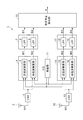
以下、実施形態について図面を参照しつつ説明する。図1は本実施形態における電波到来角度検出装置1の主要構成を示したブロック図である。第1の受信アンテナ2は、送信装置(不図示)から電波として送信された信号波を第1の信号波W1として受信する。第1の受信アンテナ2によって受信された第1の信号波W1は、ローノイズアンプ(LNA)3によって増幅される。
Hereinafter, embodiments will be described with reference to the drawings. FIG. 1 is a block diagram illustrating a main configuration of a radio wave arrival angle detection device 1 according to the present embodiment. The first receiving
発振器11は、送信装置から送信される信号波と同一の周波数の発振波を出力する。本実施形態では、発振器11は、正弦波Iと余弦波Qとを発振波として発振する。
The
第1の乗算器4は、LNA3から入力された第1の信号波W1と発振器11から入力された正弦波I、余弦波Qとの乗算により、第1の混合波としての混合波M1と混合波M2とを出力する。混合波M1は、第1の乗算器4に備えられた正弦波乗算部5によって、第1の信号波W1と正弦波Iとの乗算により出力される。混合波M2は、第1の乗算器4に備えられた余弦波乗算部6によって、第1の信号波W1と余弦波Qとの乗算により出力される。
The
第1のフィルター7は、第1の混合波である混合波M1,M2から第1の直流成分としての直流成分D1,D2を抽出する。直流成分D1は、第1のフィルター7に備えられたローパスフィルター(LPF)8により、混合波M1から抽出される。直流成分D2は、第1のフィルター7に備えられたローパスフィルター(LPF)9により、混合波M2から抽出される。
The
第2の受信アンテナ12は、送信装置から電波として送信された信号波を第2の信号波W2として受信する。第2の受信アンテナ12によって受信された第2の信号波W2は、ローノイズアンプ(LNA)13によって増幅される。
The second receiving
第2の乗算器14は、LNA13から入力された第2の信号波W2と発振器11から入力された正弦波I、余弦波Qとの乗算により、第2の混合波としての混合波M3と混合波M4とを出力する。混合波M3は、第2の乗算器14に備えられた正弦波乗算部15によって、第2の信号波W2と正弦波Iとの乗算により出力される。混合波M4は、第2の乗算器14に備えられた余弦波乗算部16によって、第2の信号波W2と余弦波Qとの乗算により出力される。
The
第2のフィルター17は、第2の混合波である混合波M3,M4から第2の直流成分としての直流成分D3,D4を抽出する。直流成分D3は、第2のフィルター17に備えられたローパスフィルター(LPF)18により、混合波M3から抽出される。直流成分D4は、第2のフィルター17に備えられたローパスフィルター(LPF)19により、混合波M4から抽出される。
The
到来角度算出部10は、AD変換部(不図示)、CPU(不図示)、RAM(不図示)、ROM(不図示)を含んで構成される。AD変換部は、直流成分D1,D2,D3,D4をアナログ量からデジタル量に変換する。また、到来角度算出部10は、CPUが、ROMに格納されたプログラムをRAMに読み出して実行することにより機能する。
The arrival
ROMには、三角関数の値と逆三角関数の値とが記憶されたテーブルが備えられ、三角関数の値から逆三角関数の値としての角度を算出することができる。到来角度算出部10は、AD変換部によって変換されたデジタル量に基づいて、送信装置から送信された信号波の到来角度を算出する。
The ROM is provided with a table storing trigonometric function values and inverse trigonometric function values, and an angle as an inverse trigonometric function value can be calculated from the trigonometric function values. The arrival
次に、信号波の到来角度を算出する方法について具体的に説明する。 Next, a method for calculating the arrival angle of the signal wave will be specifically described.
第1の信号波W1は、角周波数α、時間t、位相φ1とすると、式(1)の余弦波として表される。
W1=cos(αt+φ1) ・・・式(1)
The first signal wave W1 is represented as a cosine wave of the equation (1) when the angular frequency α, the time t, and the phase φ1 are used.
W1 = cos (αt + φ1) (1)
発振器11は、角周波数βとする式(2)の正弦波Iと式(3)の余弦波Qを発振する。
I=sinβt ・・・式(2)
Q=cosβt ・・・式(3)
The
I = sin βt (2)
Q = cos βt (3)
第1の乗算器4に備えられた正弦波乗算部5は、LNA3から入力された第1の信号波W1と、発振器11から入力された正弦波Iとの乗算を行い、式(4)の混合波M1を出力する。
M1=W1×I
=cos(αt+φ1)×sinβt
=[sin{(α+β)t+φ1}+sin{(α−β)t+φ1}]/2
・・・式(4)
The sine
M1 = W1 × I
= Cos (αt + φ1) × sinβt
= [Sin {(α + β) t + φ1} + sin {(α−β) t + φ1}] / 2
... Formula (4)
LPF8は、混合波M1のうち、高域周波数を遮断し、低域周波数のみを通過させ、混合波M1は、式(5)で表される。
M1=[sin{(α−β)t+φ1}]/2 ・・・式(5)
The
M1 = [sin {(α−β) t + φ1}] / 2 Formula (5)
発振器11が発振する正弦波Iにおける周波数は、第1の信号波W1の周波数と同じであるので、正弦波Iにおける角周波数βは、第1の信号波W1の角周波数αと同じである。従って、LPF8は、混合波M1に含まれる式(6)の直流成分D1を抽出する。
D1=(sinφ1)/2 ・・・式(6)
Since the frequency of the sine wave I generated by the
D1 = (sin φ1) / 2 Formula (6)
第1の乗算器4に備えられた余弦波乗算部6は、LNA3から入力された第1の信号波W1と、発振器11から入力された余弦波Qとの乗算を行い、式(7)の混合波M2を出力する。
M2=W1×Q
=cos(αt+φ1)×cosβt
=[cos{(α+β)t+φ1}+cos{(α−β)t+φ1}]/2
・・・式(7)
The cosine
M2 = W1 × Q
= Cos (αt + φ1) × cosβt
= [Cos {(α + β) t + φ1} + cos {(α−β) t + φ1}] / 2
... Formula (7)
LPF9は、混合波M2のうち、高域周波数を遮断し、低域周波数のみを通過させ、混合波M2は、式(8)で表される。
M2=[cos{(α−β)t+φ1}]/2 ・・・式(8)
The
M2 = [cos {(α−β) t + φ1}] / 2 (8)
余弦波Qにおける角周波数βは、第1の信号波W1の角周波数αと同じである。従って、LPF9は、混合波M2に含まれる式(9)の直流成分D2を抽出する。
D2=(cosφ1)/2 ・・・式(9)
The angular frequency β in the cosine wave Q is the same as the angular frequency α of the first signal wave W1. Therefore, the
D2 = (cosφ1) / 2 Formula (9)
第2の信号波W2は、角周波数α、時間t、位相φ2とすると、式(10)の余弦波として表される。
W2=cos(αt+φ2) ・・・式(10)
The second signal wave W2 is represented as a cosine wave of Expression (10) when the angular frequency α, the time t, and the phase φ2 are used.
W2 = cos (αt + φ2) (10)
第2の乗算器14に備えられた正弦波乗算部15は、LNA13から入力された第2の信号波W2と、発振器11から入力された正弦波Iとの乗算を行い、式(11)の混合波M3を出力する。
M3=W2×I
=cos(αt+φ2)×sinβt
=[sin{(α+β)t+φ2}+sin{(α−β)t+φ2}]/2
・・・式(11)
The sine
M3 = W2 × I
= Cos (αt + φ2) × sinβt
= [Sin {(α + β) t + φ2} + sin {(α−β) t + φ2}] / 2
... Formula (11)
LPF18は、混合波M3のうち、高域周波数を遮断し、低域周波数のみを通過させ、混合波M3は、式(12)で表される。
M3=[sin{(α−β)t+φ2}]/2 ・・・式(12)
The
M3 = [sin {(α−β) t + φ2}] / 2 (12)
発振器11が発振する正弦波Iにおける周波数は、第2の信号波W2の周波数と同じであるので、正弦波Iにおける角周波数βは、第2の信号波W2の角周波数αと同じである。従って、LPF18は、混合波M3に含まれる式(13)の直流成分D3を抽出する。
D3=(sinφ2)/2 ・・・式(13)
Since the frequency of the sine wave I oscillated by the
D3 = (sinφ2) / 2 Formula (13)
第2の乗算器14に備えられた余弦波乗算部16は、LNA13から入力された第2の信号波W2と、発振器11から入力された余弦波Qとの乗算を行い、式(14)の混合波M4を出力する。
M4=W2×Q
=cos(αt+φ2)×cosβt
=[cos{(α+β)t+φ2}+cos{(α−β)t+φ2}]/2
・・・式(14)
The cosine
M4 = W2 × Q
= Cos (αt + φ2) × cosβt
= [Cos {(α + β) t + φ2} + cos {(α−β) t + φ2}] / 2
... Formula (14)
LPF19は、混合波M4のうち、高域周波数を遮断し、低域周波数のみを通過させ、混合波M4は、式(15)で表される。
M4=[cos{(α−β)t+φ2}]/2 ・・・式(15)
The
M4 = [cos {(α−β) t + φ2}] / 2 Formula (15)
余弦波Qにおける角周波数βは、第2の信号波W2の角周波数αと同じである。従って、LPF19は、混合波M4に含まれる式(16)の直流成分D4を抽出する。
D4=(cosφ2)/2 ・・・式(16)
The angular frequency β in the cosine wave Q is the same as the angular frequency α of the second signal wave W2. Therefore, the
D4 = (cosφ2) / 2 Formula (16)
到来角度算出部10は、式(6)の直流成分D1と式(9)の直流成分D2とをアナログ量からデジタル量に変換し、式(17)の正接値を算出する。
tanφ1=sinφ1/cosφ1
=D1/D2 ・・・式(17)
The arrival
tanφ1 = sinφ1 / cosφ1
= D1 / D2 Formula (17)
到来角度算出部10は、式(13)の直流成分D3と式(16)の直流成分D4とをアナログ量からデジタル量に変換し、式(18)の正接値を算出する。
tanφ2=sinφ2/cosφ2
=D3/D4 ・・・式(18)
The arrival
tanφ2 = sinφ2 / cosφ2
= D3 / D4 Formula (18)
到来角度算出部10は、式(17)の正接値の逆三角関数となる第1の信号波W1の位相φ1と、式(18)の正接値の逆三角関数となる第2の信号波W2の位相φ2とを算出し、式(19)に示すように、位相φ1と位相φ2との差である位相差Δλを算出する。Δλ=φ1−φ2
=tan-1 φ1−tan-1φ2 ・・・式(19)
The arrival
= Tan -1 φ1-tan -1 φ2 (19)
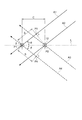
図2は、位相差Δλと電波到来角度との関係を説明するための図である。第1の受信アンテナ2と第2の受信アンテナ12とによって受信される信号波は、第1の受信アンテナ2と第2の受信アンテナ12を結ぶ直線Lに対する電波到来角度が+θである信号波A1,A2、または、直線Lに対する電波到来角度が−θである信号波A3,A4である。第1の受信アンテナ2と第2の受信アンテナ12とによって、信号波A1,A2が受信される場合について説明する。
FIG. 2 is a diagram for explaining the relationship between the phase difference Δλ and the radio wave arrival angle. A signal wave received by the
第2の受信アンテナ12の位置P2から信号波A1へ向かう垂線との交点を位置P3とする。信号波A1,A2が送信装置から同時に送信されると、信号波A1が位置P3に到達する時点と、信号波A2が位置P2に到達して第2の受信アンテナ12によって受信される時点とは同じである。
An intersection point with a perpendicular line from the position P2 of the
信号波A1は、さらに位置P3から第1の受信アンテナ2の位置P1までの距離Sを進み、位置P1に到達した時点で、第1の受信アンテナ2によって受信される。従って、信号波A1が第1の受信アンテナ2によって受信される時点と、信号波A2が第2の受信アンテナ12によって受信される時点との時間差が生じることから、第1の受信アンテナ2によって受信される第1の信号波W1の位相φ1と、第2の受信アンテナ12によって受信される第2の信号波W2の位相φ2との間には、位相差Δλが生じることになる。
The signal wave A1 further travels a distance S from the position P3 to the position P1 of the
第1の受信アンテナ2の位置P1と第2の受信アンテナ12の位置P2とは、信号波A1,A2の波長未満の距離Cで離れて備えられている。このようにすることにより、第1の受信アンテナ2によって第1の信号波W1として受信される時点と、第2の受信アンテナ12によって第2の信号波W2として受信される時点との時間差が、1周期未満となる。すなわち、位相差Δλの値は、2πラジアン未満(360度未満)とすることができる。
The position P1 of the
信号波A1の速度をVとし、信号波A1が位置P3から位置P1まで進む時間をΔtとすると、距離Sは、式(20)で表される。
S=VΔt ・・・式(20)
If the velocity of the signal wave A1 is V and the time that the signal wave A1 travels from the position P3 to the position P1 is Δt, the distance S is expressed by Expression (20).
S = VΔt (20)
時間Δtは、信号波A1の周波数をfとすると、
Δt=Δλ/2π・1/fであるので、距離Sは、式(21)となる。
S=V(Δλ/2π・1/f) ・・・式(21)
The time Δt is given by assuming that the frequency of the signal wave A1 is f.
Since Δt = Δλ / 2π · 1 / f, the distance S is expressed by Equation (21).
S = V (Δλ / 2π · 1 / f) (21)
ここで、V/2π・1/fを定数Kとすると、距離Sは式(22)となる。
S=KΔλ ・・・式(22)
Here, when V / 2π · 1 / f is a constant K, the distance S is expressed by Equation (22).
S = KΔλ Expression (22)
一方、図2から距離Sは、距離Cと電波到来角度θとから、式(23)で表される。
S=Ccosθ ・・・式(23)
On the other hand, the distance S from FIG. 2 is expressed by the equation (23) from the distance C and the radio wave arrival angle θ.
S = C cos θ (23)
従って、KΔλ=Ccosθ であるので、式(24)の余弦値が算出される。
cosθ=KΔλ/C ・・・式(24)
Therefore, since KΔλ = C cos θ, the cosine value of Equation (24) is calculated.
cos θ = KΔλ / C (24)
信号波A1,A2の電波到来角度θは、余弦値の逆三角関数の値であるので式(25)によって算出される。
θ=cos-1(KΔλ/C) ・・・式(25)
The radio wave arrival angle θ of the signal waves A1 and A2 is a value of an inverse trigonometric function of a cosine value, and thus is calculated by Expression (25).
θ = cos −1 (KΔλ / C) (25)
到来角度算出部10は、式(25)に示すように、定数K、式(19)によって算出された位相差Δλ、図2の距離Cに基づいて、信号波A1,A2の電波到来角度θを算出する。
As shown in equation (25), the arrival
第1の受信アンテナ2と第2の受信アンテナ12とによって、信号波A3,A4が受信される場合についても同様である。第2の受信アンテナ12の位置P2から信号波A4に向かう垂線との交点を位置P4とする。送信装置から同時に送信された信号波A3,A4が、位置P2と位置P4に到達する時点は同じで、信号波A4は、さらに位置P4から位置P1までの距離Sを進み、第1の受信アンテナ2に到達する。従って、第1の受信アンテナ2によって受信される第1の信号波W1の位相φ1と、第2の受信アンテナ12によって受信される第2の信号波W2の位相φ2とは、位相差Δλが生じることになる。上述した方法により、電波到来角度検出装置1によって電波到来角度−θを検出することができる。
The same applies to the case where the signal waves A3 and A4 are received by the
このようにすることによって、予め座標位置が認識された複数の電波到来角度検出装置1によって、信号波の電波到来角度を検出し、三角測量の方法によって、信号波を送信する送信装置の位置を測定することができる。あるいは、予め座標位置が認識された複数の送信装置から送信される信号波の到来角度を検出し、三角測量の方法によって、電波到来角度検出装置1の位置を測定することができる。 By doing so, the radio wave arrival angle of the signal wave is detected by the plurality of radio wave arrival angle detection devices 1 whose coordinate positions are recognized in advance, and the position of the transmission device that transmits the signal wave is determined by the triangulation method. Can be measured. Alternatively, the arrival angle of signal waves transmitted from a plurality of transmission devices whose coordinate positions are recognized in advance can be detected, and the position of the radio wave arrival angle detection device 1 can be measured by a triangulation method.
以上、本実施形態で説明した電波到来角度検出装置1は、送信装置から送信された信号波を第1の信号波W1として受信する第1の受信アンテナ2と、信号波の波長未満の距離Cで第1の受信アンテナ2から離れて位置し、送信装置から送信された信号波を第2の信号波W2として受信する第2の受信アンテナ12と、信号波と同一の周波数の発振波としての正弦波Iと余弦波Qとを出力する発振器11と、第1の信号波W1と発振波との乗算により第1の混合波としての混合波M1,M2を出力する第1の乗算器4と、第1の混合波に含まれる第1の直流成分としての直流成分D1,D2を抽出する第1のフィルター7と、第2の信号波W2と発振波との乗算により第2の混合波としての混合波M3,M4を出力する第2の乗算器14と、第2の混合波に含まれる第2の直流成分としての直流成分D3,D4を抽出する第2のフィルター17と、第1の直流成分と第2の直流成分とから第1の信号波W1と第2の信号波W2との位相差Δλを算出し、位相差Δλと距離Cとから信号波の到来角度を算出する到来角度算出部10と、を備える。
As described above, the radio wave arrival angle detection device 1 described in the present embodiment includes the
この構成によれば、第1の乗算器4は、第1の信号波W1と、第1の信号波W1と同じ周波数の発振波とを乗算し、第2の乗算器14は、第2の信号波W2と、第2の信号波W2と同じ周波数の発振波とを乗算する。これにより、第1の混合波としての混合波M1,M2には第1の直流成分としての直流成分D1,D2がそれぞれ含まれ、第2の混合波としての混合波M3,M4には第2の直流成分としての直流成分D3,D4がそれぞれ含まれる。
According to this configuration, the
また、第1の受信アンテナ2と第2の受信アンテナ12とは、信号波の波長未満の距離Cで離れて位置する。これにより、第1の受信アンテナ2によって第1の信号波W1として受信される時点と第2の受信アンテナ12によって第2の信号波W2として受信される時点との時間差が、1周期未満となる。すなわち、第1の信号波W1と第2の信号波W2との位相差Δλの値は2πラジアン未満(360度未満)である。
Further, the
到来角度算出部10は、第1のフィルター7によって抽出された直流成分D1,D2と、第2のフィルター17によって抽出された直流成分D3,D4とから第1の信号波W1と第2の信号波W2との位相差Δλを算出し、算出した位相差Δλと、第1の受信アンテナ2と第2の受信アンテナ12の距離Cとから信号波の電波到来角度θを算出する。従って、到来角度算出部10は、時間の関数を含まずに送信装置から送信された信号波の電波到来角度θを算出することができる。そのため、送信装置には、高精度な計時装置を備える必要がない。従って、高精度に時刻を補正する必要がない。
The arrival
また、本実施形態で説明した電波到来角度検出方法は、第1の受信アンテナ2によって送信装置から送信された信号波を第1の信号波W1として受信する第1の受信工程と、信号波の波長未満の距離Cで第1の受信アンテナ2から離れて位置する第2の受信アンテナ12によって送信装置から送信された信号波を第2の信号波W2として受信する第2の受信工程と、信号波と同一の周波数の発振波としての正弦波Iと余弦波Qとを出力する発振工程と、第1の信号波W1と発振波との乗算により第1の混合波としての混合波M1,M2を出力する第1の乗算工程と、第1の混合波に含まれる第1の直流成分としての直流成分D1,D2を抽出する第1の直流成分抽出工程と、第2の信号波W2と発振波との乗算により第2の混合波としての混合波M3,M4を出力する第2の乗算工程と、第2の混合波に含まれる第2の直流成分としての直流成分D3,D4を抽出する第2の直流成分抽出工程と、直流成分D1,D2,D3,D4から第1の信号波W1と第2の信号波W2との位相差Δλを算出し、位相差Δλと距離Cとから信号波の到来角度を算出する到来角度算出工程と、を含む。 The radio wave arrival angle detection method described in the present embodiment includes a first reception step of receiving a signal wave transmitted from a transmission device by the first reception antenna 2 as a first signal wave W1, and a signal wave A second receiving step of receiving a signal wave transmitted from the transmitting device by the second receiving antenna 12 located away from the first receiving antenna 2 at a distance C less than the wavelength as the second signal wave W2, and a signal An oscillating step for outputting a sine wave I and a cosine wave Q as an oscillating wave having the same frequency as the wave, and a mixed wave M1, M2 as a first mixed wave by multiplication of the first signal wave W1 and the oscillating wave , A first DC component extraction step for extracting DC components D1 and D2 as the first DC components included in the first mixed wave, a second signal wave W2 and oscillation Mixing as a second mixed wave by multiplication with a wave A second multiplication step for outputting the waves M3 and M4, a second DC component extraction step for extracting DC components D3 and D4 as second DC components included in the second mixed wave, and a DC component D1, An arrival angle calculation step of calculating a phase difference Δλ between the first signal wave W1 and the second signal wave W2 from D2, D3, D4, and calculating an arrival angle of the signal wave from the phase difference Δλ and the distance C; including.
この構成によれば、第1の乗算工程では、第1の信号波W1と、第1の信号波W1と同じ周波数の発振波とを乗算し、第2の乗算工程では、第2の信号波W2と、第2の信号波W2と同じ周波数の発振波とを乗算する。これにより、第1の混合波としての混合波M1,M2には第1の直流成分としての直流成分D1,D2がそれぞれ含まれ、第2の混合波としての混合波M3,M4には第2の直流成分としての直流成分D3,D4がそれぞれ含まれる。 According to this configuration, in the first multiplication step, the first signal wave W1 is multiplied by the oscillation wave having the same frequency as the first signal wave W1, and in the second multiplication step, the second signal wave is multiplied. Multiply W2 by an oscillation wave having the same frequency as the second signal wave W2. Accordingly, the mixed waves M1 and M2 as the first mixed wave include the DC components D1 and D2 as the first DC component, respectively, and the mixed waves M3 and M4 as the second mixed wave have the second DC components D3 and D4 are included as DC components.
また、第1の受信工程で用いる第1の受信アンテナ2と第2の受信工程で用いる第2の受信アンテナ12とは、信号波の波長未満の距離Cで離れて位置する。これにより、第1の受信アンテナ2によって第1の信号波W1として受信される時点と第2の受信アンテナ12によって第2の信号波W2として受信される時点との時間差が、1周期未満となる。すなわち、第1の信号波W1と第2の信号波W2との位相差Δλの値は2πラジアン未満(360度未満)である。
In addition, the
到来角度算出工程では、第1のフィルター7によって抽出された直流成分D1,D2と、第2のフィルター17によって抽出された直流成分D3,D4とから第1の信号波W1と第2の信号波W2との位相差Δλを算出し、算出した位相差Δλと、第1の受信アンテナ2と第2の受信アンテナ12の距離Cとから信号波の電波到来角度θを算出する。従って、到来角度算出工程では、時間の関数を含まずに送信装置から送信された信号波の電波到来角度θを算出することができる。そのため、送信装置には、高精度な計時装置を備える必要がない。従って、高精度に時刻を補正する必要がない。
In the arrival angle calculation step, the first signal wave W1 and the second signal wave are obtained from the DC components D1 and D2 extracted by the
1…電波到来角度検出装置、2…第1の受信アンテナ、4…第1の乗算器、5,15…正弦波乗算部、6,16…余弦波乗算部、7…第1のフィルター、8,9,18,19…LPF、10…到来角度算出部、11…発振器、12…第2の受信アンテナ、14…第2の乗算器、17…第2のフィルター、A1〜A4…信号波、C…距離、D1〜D4…直流成分、I…正弦波、M1〜M4…混合波、Q…余弦波、W1…第1の信号波、W2…第2の信号波、θ…電波到来角度。 DESCRIPTION OF SYMBOLS 1 ... Radio wave arrival angle detection apparatus, 2 ... 1st receiving antenna, 4 ... 1st multiplier, 5,15 ... Sine wave multiplication part, 6, 16 ... Cosine wave multiplication part, 7 ... 1st filter, 8 , 9, 18, 19 ... LPF, 10 ... arrival angle calculation unit, 11 ... oscillator, 12 ... second receiving antenna, 14 ... second multiplier, 17 ... second filter, A1-A4 ... signal wave, C: Distance, D1-D4: DC component, I: Sine wave, M1-M4 ... Mixed wave, Q ... Cosine wave, W1 ... First signal wave, W2 ... Second signal wave, [theta] ... Radio wave arrival angle.
Claims (2)
前記信号波の波長未満の距離で前記第1の受信アンテナから離れて位置し、前記送信装置から送信された前記信号波を第2の信号波として受信する第2の受信アンテナと、
前記信号波と同一の周波数の発振波を出力する発振器と、
前記第1の信号波と前記発振波との乗算により第1の混合波を出力する第1の乗算器と、
前記第1の混合波に含まれる第1の直流成分を抽出する第1のフィルターと、
前記第2の信号波と前記発振波との乗算により第2の混合波を出力する第2の乗算器と、
前記第2の混合波に含まれる第2の直流成分を抽出する第2のフィルターと、
前記第1の直流成分と前記第2の直流成分とから前記第1の信号波と前記第2の信号波との位相差を算出し、前記位相差と前記距離とから前記信号波の到来角度を算出する到来角度算出部と、
を備えたことを特徴とする電波到来角度検出装置。 A first receiving antenna for receiving a signal wave transmitted from the transmission device as a first signal wave;
A second receiving antenna that is located away from the first receiving antenna at a distance less than the wavelength of the signal wave and receives the signal wave transmitted from the transmitting device as a second signal wave;
An oscillator that outputs an oscillation wave having the same frequency as the signal wave;
A first multiplier that outputs a first mixed wave by multiplication of the first signal wave and the oscillation wave;
A first filter for extracting a first DC component contained in the first mixed wave;
A second multiplier that outputs a second mixed wave by multiplication of the second signal wave and the oscillation wave;
A second filter for extracting a second direct current component contained in the second mixed wave;
The phase difference between the first signal wave and the second signal wave is calculated from the first DC component and the second DC component, and the arrival angle of the signal wave is calculated from the phase difference and the distance. An arrival angle calculation unit for calculating
A radio wave arrival angle detection device comprising:
前記信号波の波長未満の距離で前記第1の受信アンテナから離れて位置する第2の受信アンテナによって前記送信装置から送信された前記信号波を第2の信号波として受信する第2の受信工程と、
前記信号波と同一の周波数の発振波を出力する発振工程と、
前記第1の信号波と前記発振波との乗算により第1の混合波を出力する第1の乗算工程と、
前記第1の混合波に含まれる第1の直流成分を抽出する第1の直流成分抽出工程と、
前記第2の信号波と前記発振波との乗算により第2の混合波を出力する第2の乗算工程と、
前記第2の混合波に含まれる第2の直流成分を抽出する第2の直流成分抽出工程と、
前記第1の直流成分と前記第2の直流成分とから前記第1の信号波と前記第2の信号波との位相差を算出し、前記位相差と前記距離とから前記信号波の到来角度を算出する到来角度算出工程と、
を含むことを特徴とする電波到来角度検出方法。 A first reception step of receiving a signal wave transmitted from the transmission device by the first reception antenna as a first signal wave;
A second receiving step of receiving, as a second signal wave, the signal wave transmitted from the transmitting device by a second receiving antenna located at a distance less than the wavelength of the signal wave and away from the first receiving antenna; When,
An oscillation step of outputting an oscillation wave having the same frequency as the signal wave;
A first multiplication step of outputting a first mixed wave by multiplication of the first signal wave and the oscillation wave;
A first DC component extracting step of extracting a first DC component contained in the first mixed wave;
A second multiplication step of outputting a second mixed wave by multiplication of the second signal wave and the oscillation wave;
A second DC component extracting step of extracting a second DC component contained in the second mixed wave;
The phase difference between the first signal wave and the second signal wave is calculated from the first DC component and the second DC component, and the arrival angle of the signal wave is calculated from the phase difference and the distance. An arrival angle calculation step of calculating
A radio wave arrival angle detection method comprising:
Priority Applications (3)
| Application Number | Priority Date | Filing Date | Title |
|---|---|---|---|
| JP2010110873A JP2011237359A (en) | 2010-05-13 | 2010-05-13 | Device and method for detecting radio wave arrival angle |
| US13/105,767 US20110281539A1 (en) | 2010-05-13 | 2011-05-11 | Radio wave arrival angle detecting device and radio wave arrival angle detecting method |
| CN2011101247563A CN102288939A (en) | 2010-05-13 | 2011-05-13 | Radio wave arrival angle detecting device and radio wave arrival angle detecting method |
Applications Claiming Priority (1)
| Application Number | Priority Date | Filing Date | Title |
|---|---|---|---|
| JP2010110873A JP2011237359A (en) | 2010-05-13 | 2010-05-13 | Device and method for detecting radio wave arrival angle |
Publications (2)
| Publication Number | Publication Date |
|---|---|
| JP2011237359A true JP2011237359A (en) | 2011-11-24 |
| JP2011237359A5 JP2011237359A5 (en) | 2013-06-20 |
Family
ID=44912196
Family Applications (1)
| Application Number | Title | Priority Date | Filing Date |
|---|---|---|---|
| JP2010110873A Withdrawn JP2011237359A (en) | 2010-05-13 | 2010-05-13 | Device and method for detecting radio wave arrival angle |
Country Status (3)
| Country | Link |
|---|---|
| US (1) | US20110281539A1 (en) |
| JP (1) | JP2011237359A (en) |
| CN (1) | CN102288939A (en) |
Families Citing this family (15)
| Publication number | Priority date | Publication date | Assignee | Title |
|---|---|---|---|---|
| JP6205774B2 (en) * | 2013-03-22 | 2017-10-04 | セイコーエプソン株式会社 | Detection circuit, semiconductor integrated circuit device, magnetic field rotation angle detection device, and electronic device |
| CN105676212B (en) * | 2016-03-30 | 2018-05-04 | 安徽四创电子股份有限公司 | A kind of short range range radar system and the target measuring method based on the system |
| CN107677990A (en) * | 2017-11-01 | 2018-02-09 | 北京全迹科技有限公司 | A kind of positioner and localization method |
| JP6860121B2 (en) * | 2018-08-03 | 2021-04-14 | 株式会社村田製作所 | Radio wave arrival direction estimation device |
| US10819539B2 (en) * | 2018-12-05 | 2020-10-27 | Electronics And Telecommunications Research Institute | Signal source estimation method and apparatus performing the same |
| CN109884584B (en) * | 2019-01-23 | 2020-10-30 | 李超 | A positioning method, device and terminal equipment |
| US11815611B2 (en) * | 2019-10-15 | 2023-11-14 | Avago Technologies International Sales Pte. Limited | Angle-of-arrival detection using a dual-core bluetooth receiver |
| JP7455565B2 (en) * | 2019-12-09 | 2024-03-26 | 三菱重工業株式会社 | Signal processing device, signal processing method, and signal processing program |
| CN114839591B (en) * | 2021-02-01 | 2025-09-05 | 中国移动通信有限公司研究院 | A method, device and apparatus for measuring signal arrival angle based on array antenna |
| US11791663B2 (en) | 2021-02-10 | 2023-10-17 | Nucurrent, Inc. | Slotted communications in virtual AC power signal transfer |
| US11764617B2 (en) | 2021-02-10 | 2023-09-19 | Nucurrent, Inc. | Wireless power receivers for virtual AC power signals |
| US11923695B2 (en) | 2021-02-10 | 2024-03-05 | Nucurrent, Inc. | Wireless power transmitters for virtual AC power signals |
| US11289952B1 (en) | 2021-02-10 | 2022-03-29 | Nucurrent, Inc. | Slotted communications in virtual AC power signal transfer with variable slot width |
| US11942797B2 (en) | 2021-02-10 | 2024-03-26 | Nucurrent, Inc. | Virtual AC power signal transfer using wireless power transfer system |
| US11444492B2 (en) | 2021-02-10 | 2022-09-13 | Nucurrent, Inc. | Wireless power transfer systems for kitchen appliances |
Citations (9)
| Publication number | Priority date | Publication date | Assignee | Title |
|---|---|---|---|---|
| JPH01224683A (en) * | 1988-03-04 | 1989-09-07 | Mitsubishi Electric Corp | Azimuth detecting and receiving device |
| JPH06118154A (en) * | 1992-09-30 | 1994-04-28 | Taiyo Musen Kk | Direction detector |
| JPH06160522A (en) * | 1992-11-13 | 1994-06-07 | Japan Radio Co Ltd | Fish finder for weighing |
| JPH09236648A (en) * | 1996-02-29 | 1997-09-09 | Taiyo Musen Kk | Direction finder |
| JP2001022987A (en) * | 1999-07-07 | 2001-01-26 | Mitsubishi Heavy Ind Ltd | Road toll collecting device and automatic toll collecting system |
| JP2005062144A (en) * | 2003-08-14 | 2005-03-10 | Taiyo Musen Co Ltd | Direction finding system |
| JP2006250870A (en) * | 2005-03-14 | 2006-09-21 | Mitsubishi Electric Corp | Partial discharge position locator |
| JP2007127455A (en) * | 2005-11-01 | 2007-05-24 | Nippon Soken Inc | Object location detection apparatus |
| JP2009192359A (en) * | 2008-02-14 | 2009-08-27 | Toyota Motor Corp | Radar device |
Family Cites Families (5)
| Publication number | Priority date | Publication date | Assignee | Title |
|---|---|---|---|---|
| US5815117A (en) * | 1997-01-02 | 1998-09-29 | Raytheon Company | Digital direction finding receiver |
| US6198436B1 (en) * | 1999-01-29 | 2001-03-06 | Ail Systems, Inc. | Integrated interferometer and instantaneous frequency measurement device and method |
| JP2001229871A (en) * | 2000-02-15 | 2001-08-24 | Hitachi Ltd | Ion implanter |
| US6839025B1 (en) * | 2002-06-03 | 2005-01-04 | Ken Reigle | Precision direction finding sensing systems and methods |
| CN201047870Y (en) * | 2007-04-26 | 2008-04-16 | 王新民 | Antenna apparatus integration laser instructed broadband electromagnetic wave positioner |
-
2010
- 2010-05-13 JP JP2010110873A patent/JP2011237359A/en not_active Withdrawn
-
2011
- 2011-05-11 US US13/105,767 patent/US20110281539A1/en not_active Abandoned
- 2011-05-13 CN CN2011101247563A patent/CN102288939A/en active Pending
Patent Citations (9)
| Publication number | Priority date | Publication date | Assignee | Title |
|---|---|---|---|---|
| JPH01224683A (en) * | 1988-03-04 | 1989-09-07 | Mitsubishi Electric Corp | Azimuth detecting and receiving device |
| JPH06118154A (en) * | 1992-09-30 | 1994-04-28 | Taiyo Musen Kk | Direction detector |
| JPH06160522A (en) * | 1992-11-13 | 1994-06-07 | Japan Radio Co Ltd | Fish finder for weighing |
| JPH09236648A (en) * | 1996-02-29 | 1997-09-09 | Taiyo Musen Kk | Direction finder |
| JP2001022987A (en) * | 1999-07-07 | 2001-01-26 | Mitsubishi Heavy Ind Ltd | Road toll collecting device and automatic toll collecting system |
| JP2005062144A (en) * | 2003-08-14 | 2005-03-10 | Taiyo Musen Co Ltd | Direction finding system |
| JP2006250870A (en) * | 2005-03-14 | 2006-09-21 | Mitsubishi Electric Corp | Partial discharge position locator |
| JP2007127455A (en) * | 2005-11-01 | 2007-05-24 | Nippon Soken Inc | Object location detection apparatus |
| JP2009192359A (en) * | 2008-02-14 | 2009-08-27 | Toyota Motor Corp | Radar device |
Also Published As
| Publication number | Publication date |
|---|---|
| US20110281539A1 (en) | 2011-11-17 |
| CN102288939A (en) | 2011-12-21 |
Similar Documents
| Publication | Publication Date | Title |
|---|---|---|
| JP2011237359A (en) | Device and method for detecting radio wave arrival angle | |
| JP5407856B2 (en) | Multiband transceiver and positioning system using the transceiver | |
| JP2011237359A5 (en) | ||
| US10057798B2 (en) | Methods and systems for measuring range between devices | |
| JP2007093576A (en) | Distance measuring device and distance measuring method | |
| CN103416036B (en) | Quadrature demodulator | |
| CN102331290B (en) | Method and apparatus for solving zero point problem of non-contact vibration measurement with utilization of phase control | |
| JPWO2008029812A1 (en) | Distance measuring device | |
| JP6130195B2 (en) | Radar system | |
| JP5443328B2 (en) | Transceiver | |
| JP5117999B2 (en) | Distance measuring device | |
| JP2014010110A (en) | Angle measurement device and angle measurement method | |
| CN212569123U (en) | Resonant frequency correction device, electronic equipment and reversing radar alarm and distance measurement system | |
| JP2006208355A (en) | Method for measuring inter radio stations distance | |
| JP2006053054A (en) | Moving speed measuring method and moving speed measuring system | |
| US20190204406A1 (en) | Apparatus and Method of Flight Measurement | |
| JP2009210372A (en) | Distance measuring device | |
| JP2008122255A (en) | Distance measuring device | |
| JP4000321B2 (en) | Distance measuring method and distance measuring method | |
| JP2001116834A (en) | Radar equipment | |
| EP2353030B1 (en) | A measurement agent, a tag, a method for measuring, a method for serving measuring and a computer program product | |
| KR20170005202A (en) | Apparatus for time synchronization using gps modules and method thereof | |
| JP2014115203A (en) | Distance measurement device | |
| CA2791076C (en) | Apparatus, and associated method, for forming a synthesized oscillating signal | |
| US20090029667A1 (en) | Communication device |
Legal Events
| Date | Code | Title | Description |
|---|---|---|---|
| A521 | Request for written amendment filed |
Free format text: JAPANESE INTERMEDIATE CODE: A523 Effective date: 20130507 |
|
| A621 | Written request for application examination |
Free format text: JAPANESE INTERMEDIATE CODE: A621 Effective date: 20130507 |
|
| A977 | Report on retrieval |
Free format text: JAPANESE INTERMEDIATE CODE: A971007 Effective date: 20140214 |
|
| A131 | Notification of reasons for refusal |
Free format text: JAPANESE INTERMEDIATE CODE: A131 Effective date: 20140225 |
|
| A761 | Written withdrawal of application |
Free format text: JAPANESE INTERMEDIATE CODE: A761 Effective date: 20140423 |