JP6205774B2 - Detection circuit, semiconductor integrated circuit device, magnetic field rotation angle detection device, and electronic device - Google Patents
Detection circuit, semiconductor integrated circuit device, magnetic field rotation angle detection device, and electronic device Download PDFInfo
- Publication number
- JP6205774B2 JP6205774B2 JP2013059601A JP2013059601A JP6205774B2 JP 6205774 B2 JP6205774 B2 JP 6205774B2 JP 2013059601 A JP2013059601 A JP 2013059601A JP 2013059601 A JP2013059601 A JP 2013059601A JP 6205774 B2 JP6205774 B2 JP 6205774B2
- Authority
- JP
- Japan
- Prior art keywords
- sensor unit
- circuit
- detection
- signal
- output signal
- Prior art date
- Legal status (The legal status is an assumption and is not a legal conclusion. Google has not performed a legal analysis and makes no representation as to the accuracy of the status listed.)
- Active
Links
Images


Classifications
-
- G—PHYSICS
- G01—MEASURING; TESTING
- G01R—MEASURING ELECTRIC VARIABLES; MEASURING MAGNETIC VARIABLES
- G01R33/00—Arrangements or instruments for measuring magnetic variables
- G01R33/02—Measuring direction or magnitude of magnetic fields or magnetic flux
- G01R33/06—Measuring direction or magnitude of magnetic fields or magnetic flux using galvano-magnetic devices
- G01R33/09—Magnetoresistive devices
-
- G—PHYSICS
- G01—MEASURING; TESTING
- G01D—MEASURING NOT SPECIALLY ADAPTED FOR A SPECIFIC VARIABLE; ARRANGEMENTS FOR MEASURING TWO OR MORE VARIABLES NOT COVERED IN A SINGLE OTHER SUBCLASS; TARIFF METERING APPARATUS; MEASURING OR TESTING NOT OTHERWISE PROVIDED FOR
- G01D5/00—Mechanical means for transferring the output of a sensing member; Means for converting the output of a sensing member to another variable where the form or nature of the sensing member does not constrain the means for converting; Transducers not specially adapted for a specific variable
- G01D5/12—Mechanical means for transferring the output of a sensing member; Means for converting the output of a sensing member to another variable where the form or nature of the sensing member does not constrain the means for converting; Transducers not specially adapted for a specific variable using electric or magnetic means
- G01D5/14—Mechanical means for transferring the output of a sensing member; Means for converting the output of a sensing member to another variable where the form or nature of the sensing member does not constrain the means for converting; Transducers not specially adapted for a specific variable using electric or magnetic means influencing the magnitude of a current or voltage
- G01D5/142—Mechanical means for transferring the output of a sensing member; Means for converting the output of a sensing member to another variable where the form or nature of the sensing member does not constrain the means for converting; Transducers not specially adapted for a specific variable using electric or magnetic means influencing the magnitude of a current or voltage using Hall-effect devices
- G01D5/145—Mechanical means for transferring the output of a sensing member; Means for converting the output of a sensing member to another variable where the form or nature of the sensing member does not constrain the means for converting; Transducers not specially adapted for a specific variable using electric or magnetic means influencing the magnitude of a current or voltage using Hall-effect devices influenced by the relative movement between the Hall device and magnetic fields
-
- G—PHYSICS
- G01—MEASURING; TESTING
- G01R—MEASURING ELECTRIC VARIABLES; MEASURING MAGNETIC VARIABLES
- G01R33/00—Arrangements or instruments for measuring magnetic variables
- G01R33/0023—Electronic aspects, e.g. circuits for stimulation, evaluation, control; Treating the measured signals; calibration
-
- G—PHYSICS
- G01—MEASURING; TESTING
- G01R—MEASURING ELECTRIC VARIABLES; MEASURING MAGNETIC VARIABLES
- G01R33/00—Arrangements or instruments for measuring magnetic variables
- G01R33/02—Measuring direction or magnitude of magnetic fields or magnetic flux
-
- G—PHYSICS
- G01—MEASURING; TESTING
- G01R—MEASURING ELECTRIC VARIABLES; MEASURING MAGNETIC VARIABLES
- G01R33/00—Arrangements or instruments for measuring magnetic variables
- G01R33/02—Measuring direction or magnitude of magnetic fields or magnetic flux
- G01R33/06—Measuring direction or magnitude of magnetic fields or magnetic flux using galvano-magnetic devices
- G01R33/09—Magnetoresistive devices
- G01R33/093—Magnetoresistive devices using multilayer structures, e.g. giant magnetoresistance sensors
Landscapes
- Physics & Mathematics (AREA)
- General Physics & Mathematics (AREA)
- Condensed Matter Physics & Semiconductors (AREA)
- Transmission And Conversion Of Sensor Element Output (AREA)
- Measurement Of Length, Angles, Or The Like Using Electric Or Magnetic Means (AREA)
Description
本発明は、磁気抵抗効果素子(以下においては、「MR素子」ともいう)を用いた磁気センサーに接続されて磁界の回転角を検出する検出回路及び半導体集積回路装置に関する。また、本発明は、そのような磁気センサーと検出回路とを含む磁界回転角検出装置に関する。さらに、本発明は、磁界回転角検出装置を用いた水道メーター、ガスメーター、速度メーター等の電子機器等に関する。 The present invention relates to a detection circuit and a semiconductor integrated circuit device which are connected to a magnetic sensor using a magnetoresistive effect element (hereinafter also referred to as “MR element”) and detect a rotation angle of a magnetic field. The present invention also relates to a magnetic field rotation angle detection device including such a magnetic sensor and a detection circuit. Furthermore, the present invention relates to electronic devices such as a water meter, a gas meter, and a speed meter using a magnetic field rotation angle detection device.
MR素子は、磁気抵抗効果のために、磁界の強さによって抵抗値が変化するという特性を有しており、MR素子に磁界が印加されると、その抵抗値は増加する。そこで、複数のMR素子をブリッジ接続することにより、回転磁界を発生する回転体の回転角を検出することが行われている。 The MR element has a characteristic that the resistance value changes depending on the strength of the magnetic field due to the magnetoresistive effect, and the resistance value increases when a magnetic field is applied to the MR element. Therefore, the rotation angle of a rotating body that generates a rotating magnetic field is detected by bridge-connecting a plurality of MR elements.
関連する技術として、特許文献1には、極めて簡単な構成の付加により、0°〜360°の範囲の回転角度検出が可能になる回転角度検出装置が開示されている。この回転角度検出装置は、検出対象に取り付けられて検出対象と共に回転して回転磁場を生成する回転磁石と、この回転磁石で生成される回転磁場内に配置され、複数のMR素子をブリッジ接続してなるセンサーユニットを互いの磁化容易軸を45°ずらして配置してなる磁気センサーと、この磁気センサーの近傍に配置され、磁気センサーが配置された領域における回転磁石による0°〜360°の回転磁場から0°〜180°の合成回転磁場を生成する4極補助磁石とを備えている。
As a related technique,
特許文献1によれば、磁気センサーの近傍に4極補助磁石が設けられているので、4極補助磁石の合成磁気モーメントと回転磁石による磁気モーメントの合成磁気モーメントが、回転磁石による0°〜360°の回転を0°〜180°の回転に変換する。これにより、磁気センサーでの0°〜180°の回転角度検出値を、検出対象の0°〜360°の回転角度検出値として求めることが可能になる。
According to
また、信号処理ための回路は、従来の回路をそのまま利用することができる。磁気センサーから出力される複数の検出信号は、複数のA/D変換回路によってそれぞれA/D変換されて、CPUに入力される。CPUは、それらの検出信号に所定の信号処理を施し、回転角度検出データを算出する。 Further, a conventional circuit can be used as it is as a signal processing circuit. A plurality of detection signals output from the magnetic sensor are A / D converted by a plurality of A / D conversion circuits and input to the CPU. The CPU performs predetermined signal processing on these detection signals to calculate rotation angle detection data.
しかしながら、磁界回転角検出装置において4極補助磁石を使用すれば、部品の実装面積やコストが大幅に増加してしまう。また、検出回路においてA/D変換回路を使用すれば、回路の消費電流やコストが大幅に増加してしまう。従って、4極補助磁石やA/D変換回路を使用せずに高精度を実現することが望まれている。その場合に、複数のMR素子をブリッジ接続して構成される2つのセンサーユニットが互いに45°ずらして配置された磁気センサーを用いて磁界の回転角を検出すれば、45°(1/8回転)の精度でしか回転角を検出することができない。 However, if a quadrupole auxiliary magnet is used in the magnetic field rotation angle detection device, the mounting area and cost of the components are significantly increased. Moreover, if an A / D conversion circuit is used in the detection circuit, the current consumption and cost of the circuit will increase significantly. Accordingly, it is desired to achieve high accuracy without using a 4-pole auxiliary magnet or an A / D conversion circuit. In this case, if the rotation angle of the magnetic field is detected using a magnetic sensor in which two sensor units configured by bridge-connecting a plurality of MR elements are arranged to be shifted from each other by 45 °, 45 ° (1/8 rotation) The rotation angle can be detected only with accuracy of).
そこで、上記の点に鑑み、本発明の目的の1つは、複数のMR素子をブリッジ接続して構成される2つのセンサーユニットが互いに所定の角度をなして配置された磁気センサーを用いて、簡単な回路構成により、45°(1/8回転)よりも細かい精度で磁界の回転角を検出することである。 Therefore, in view of the above points, one of the objects of the present invention is to use a magnetic sensor in which two sensor units configured by bridge-connecting a plurality of MR elements are arranged at a predetermined angle, It is to detect the rotation angle of the magnetic field with an accuracy finer than 45 ° (1/8 rotation) with a simple circuit configuration.
以上の課題を解決するため、本発明の第1の観点に係る検出回路は、磁気抵抗効果素子のブリッジ回路を有する第1のセンサーユニット及び第2のセンサーユニットが互いに所定の角度をなして配置された磁気センサーに接続される検出回路であって、第1又は第2のセンサーユニットの出力信号を比較する第1の比較回路と、第1のセンサーユニットの出力信号と第2のセンサーユニットの出力信号とを比較する第2の比較回路と、第1の比較回路の比較結果と第2の比較回路の比較結果とに基づいて磁界の回転角を算出する回転角算出回路とを含む。 In order to solve the above problems, in the detection circuit according to the first aspect of the present invention, the first sensor unit and the second sensor unit having a bridge circuit of magnetoresistive effect elements are arranged at a predetermined angle. A first comparison circuit for comparing the output signals of the first or second sensor unit, the output signal of the first sensor unit, and the second sensor unit. A second comparison circuit that compares the output signal; and a rotation angle calculation circuit that calculates the rotation angle of the magnetic field based on the comparison result of the first comparison circuit and the comparison result of the second comparison circuit.
本発明の第1の観点によれば、第1又は第2のセンサーユニットの出力信号を比較することに加えて、第1のセンサーユニットの出力信号と第2のセンサーユニットの出力信号とを比較することにより、45°(1/8回転)よりも細かい精度で磁界の回転角を検出することができる。 According to the first aspect of the present invention, in addition to comparing the output signal of the first or second sensor unit, the output signal of the first sensor unit and the output signal of the second sensor unit are compared. By doing so, the rotation angle of the magnetic field can be detected with an accuracy finer than 45 ° (1/8 rotation).
本発明の第2の観点に係る検出回路は、本発明の第1の観点に係る検出回路において、第1の比較回路が、第1のセンサーユニットの2つの出力信号を比較して、比較結果を表す第1の検出信号を出力する第1のコンパレーターと、第2のセンサーユニットの2つの出力信号を比較して、比較結果を表す第2の検出信号を出力する第2のコンパレーターとを含み、第2の比較回路が、第1のセンサーユニットの一方の出力信号と第2のセンサーユニットの一方の出力信号とを比較する第3のコンパレーターと、第1のセンサーユニットの他方の出力信号と第2のセンサーユニットの一方の出力信号とを比較する第4のコンパレーターとを含み、回転角算出回路が、第3のコンパレーターの比較結果と第4のコンパレーターの比較結果とに基づいて第3の検出信号を生成する論理回路を含むことを特徴とする。 The detection circuit according to the second aspect of the present invention is the detection circuit according to the first aspect of the present invention, wherein the first comparison circuit compares the two output signals of the first sensor unit and compares the result. A first comparator that outputs a first detection signal that represents the first detection signal, and a second comparator that compares the two output signals of the second sensor unit and outputs a second detection signal that represents the comparison result; A second comparator circuit for comparing one output signal of the first sensor unit with one output signal of the second sensor unit, and the other of the first sensor unit. A rotation angle calculation circuit including a comparison result of the third comparator and a comparison result of the fourth comparator; and a fourth comparator that compares the output signal with one output signal of the second sensor unit. Based on Generating a third detection signal Te, characterized in that it comprises a logic circuit.
本発明の第2の観点によれば、センサーユニット毎の2つの出力信号を比較することに加えて、第1のセンサーユニットの一方の出力信号と第2のセンサーユニットの一方の出力信号とを比較すると共に、第1のセンサーユニットの他方の出力信号と第2のセンサーユニットの一方の出力信号とを比較することにより、22.5°(1/16回転)の精度で磁界の回転角を検出することができる。 According to the second aspect of the present invention, in addition to comparing two output signals for each sensor unit, one output signal of the first sensor unit and one output signal of the second sensor unit are In addition, by comparing the other output signal of the first sensor unit with one output signal of the second sensor unit, the rotation angle of the magnetic field can be determined with an accuracy of 22.5 ° (1/16 rotation). Can be detected.
本発明の第3の観点に係る検出回路は、本発明の第1の観点に係る検出回路において、第1の比較回路が、第1のセンサーユニットの2つの出力信号を比較して、比較結果を表す第1の検出信号を出力する第1のコンパレーターを含み、第2の比較回路が、第1のセンサーユニットの出力信号を所定の増幅率で増幅して、振幅が同一で符号が互いに異なる第1の増幅信号及び第2の増幅信号を出力する増幅部と、第2のセンサーユニットの出力信号と第1の増幅信号とを比較して、比較結果を表す第2の検出信号を出力する第2のコンパレーターと、第2のセンサーユニットの出力信号と第2の増幅信号とを比較して、比較結果を表す第3の検出信号を出力する第3のコンパレーターとを含むことを特徴とする。 The detection circuit according to the third aspect of the present invention is the detection circuit according to the first aspect of the present invention, wherein the first comparison circuit compares the two output signals of the first sensor unit and compares the result. And a second comparator that amplifies the output signal of the first sensor unit with a predetermined amplification factor, and has the same amplitude but the same sign. Amplifying units that output different first and second amplified signals and the output signal of the second sensor unit and the first amplified signal are compared, and a second detection signal representing the comparison result is output. A second comparator that compares the output signal of the second sensor unit with the second amplified signal and outputs a third detection signal that represents the comparison result. Features.
本発明の第3の観点によれば、第1のセンサーユニットの2つの出力信号を比較することに加えて、第1のセンサーユニットの出力信号を所定の増幅率で増幅して符号が互いに異なる第1の増幅信号及び第2の増幅信号を求め、第2のセンサーユニットの出力信号と第1の増幅信号とを比較すると共に、第2のセンサーユニットの出力信号と第2の増幅信号とを比較することにより、30°(1/12回転)の精度で磁界の回転角を検出することができる。 According to the third aspect of the present invention, in addition to comparing the two output signals of the first sensor unit, the output signals of the first sensor unit are amplified with a predetermined amplification factor and the signs are different from each other. The first amplified signal and the second amplified signal are obtained, the output signal of the second sensor unit is compared with the first amplified signal, and the output signal of the second sensor unit and the second amplified signal are compared. By comparison, the rotation angle of the magnetic field can be detected with an accuracy of 30 ° (1/12 rotation).
本発明の第4の観点に係る検出回路は、本発明の第1の観点に係る検出回路において、第1の比較回路が、第1のセンサーユニットの2つの出力信号を比較して、比較結果を表す第1の検出信号を出力する第1のコンパレーターを含み、第2の比較回路が、第1のセンサーユニットの一方の出力信号を所定の増幅率で増幅して、増幅信号を出力する増幅部と、第2のセンサーユニットの一方の出力信号と増幅信号とを比較して、比較結果を表す第2の検出信号を出力する第2のコンパレーターと、第2のセンサーユニットの他方の出力信号と増幅信号とを比較して、比較結果を表す第3の検出信号を出力する第3のコンパレーターとを含むことを特徴とする。 A detection circuit according to a fourth aspect of the present invention is the detection circuit according to the first aspect of the present invention, wherein the first comparison circuit compares the two output signals of the first sensor unit and compares the result. And a second comparator that amplifies one output signal of the first sensor unit at a predetermined amplification rate and outputs an amplified signal. An amplification unit, a second comparator for outputting a second detection signal representing the comparison result by comparing one output signal of the second sensor unit with the amplified signal, and the other of the second sensor unit And a third comparator that compares the output signal with the amplified signal and outputs a third detection signal representing the comparison result.
本発明の第4の観点によれば、第1のセンサーユニットの2つの出力信号を比較することに加えて、第1のセンサーユニットの一方の出力信号を所定の増幅率で増幅して増幅信号を求め、第2のセンサーユニットの一方の出力信号と増幅信号とを比較すると共に、第2のセンサーユニットの他方の出力信号と増幅信号とを比較することにより、30°(1/12回転)の精度で磁界の回転角を検出することができる。 According to the fourth aspect of the present invention, in addition to comparing two output signals of the first sensor unit, one output signal of the first sensor unit is amplified at a predetermined amplification factor to obtain an amplified signal. 30 ° (1/12 rotation) by comparing one output signal of the second sensor unit with the amplified signal and comparing the other output signal of the second sensor unit with the amplified signal. The rotation angle of the magnetic field can be detected with a high accuracy.
ここで、本発明の第3又は第4の観点に係る検出回路は、電源電圧を分圧することにより、増幅部において用いられる基準電位を生成する分圧回路をさらに含むようにしても良い。その場合には、増幅信号の中点電位を所望の基準電位に近付けることができる。 Here, the detection circuit according to the third or fourth aspect of the present invention may further include a voltage dividing circuit that generates a reference potential used in the amplifying unit by dividing the power supply voltage. In that case, the midpoint potential of the amplified signal can be brought close to the desired reference potential.
本発明の幾つかの観点に係る半導体集積回路装置は、上記いずれかの検出回路を含む。A/D変換回路を使用しない検出回路を半導体集積回路装置に内蔵することにより、回路の小型化や低コスト化を達成することができる。 A semiconductor integrated circuit device according to some aspects of the present invention includes any one of the detection circuits described above. By incorporating a detection circuit that does not use an A / D conversion circuit in a semiconductor integrated circuit device, it is possible to achieve circuit miniaturization and cost reduction.
本発明の幾つかの観点に係る磁界回転角検出装置は、上記いずれかの検出回路と、磁気センサーとを含む。これにより、回転体の回転角を精度良く検出できる磁界回転角検出装置を実現することができる。 A magnetic field rotation angle detection device according to some aspects of the present invention includes any one of the detection circuits described above and a magnetic sensor. Thereby, the magnetic field rotation angle detection apparatus which can detect the rotation angle of a rotary body accurately can be implement | achieved.
本発明の幾つかの観点に係る電子機器は、上記の磁界回転角検出装置と、回転磁界を発生する回転体とを含む。これにより、水道メーター、ガスメーター、速度メーター等を実現することができる。 An electronic apparatus according to some aspects of the present invention includes the above-described magnetic field rotation angle detection device and a rotating body that generates a rotating magnetic field. Thereby, a water meter, a gas meter, a speed meter, etc. are realizable.
以下、本発明の実施形態について、図面を参照しながら詳しく説明する。
図1は、本発明の幾つかの実施形態に係る電子機器の構成の一部を示す側面図である。この電子機器は、水道メーター、ガスメーター、速度メーター等の電子機器であり、磁石10aを有する回転体10と、第1のセンサーユニット21及び第2のセンサーユニット22を有する磁気センサー20とを含んでいる。
Hereinafter, embodiments of the present invention will be described in detail with reference to the drawings.
FIG. 1 is a side view showing a part of the configuration of an electronic apparatus according to some embodiments of the present invention. This electronic device is an electronic device such as a water meter, a gas meter, and a speed meter, and includes a
例えば、回転体10は、水道水やガス等の流体の移動に伴って回転する羽根車等に接続されている。あるいは、回転体10は、モーターや車輪の回転軸であっても良い。回転体10が回転すると、磁石10aが回転磁界を発生する。磁石10aのN極からS極に向けて形成される磁束線が通過する位置に、磁気センサー20が配置されている。
For example, the rotating
第1のセンサーユニット21及び第2のセンサーユニット22の各々は、MR素子のブリッジ回路を有する。MR素子は、磁気抵抗効果のために、磁界の強さによって抵抗値が変化するという特性を有しており、MR素子に磁界が印加されると、その抵抗値は増加する。
Each of the
図2は、第1のセンサーユニットの構成及び配置方向を示す平面図である。第1のセンサーユニット21は、ブリッジ接続されたMR素子R1〜R4を有している。また、図3は、第2のセンサーユニットの構成及び配置方向を示す平面図である。第2のセンサーユニット22は、ブリッジ接続されたMR素子R5〜R8を有している。第1のセンサーユニット21及び第2のセンサーユニット22は、回転磁界を発生する回転体10の回転軸Zに略直交する面内において、互いに略45°の角度をなして配置されている。
FIG. 2 is a plan view showing the configuration and arrangement direction of the first sensor unit. The
図1に示すように、センサーユニット21及び22は、回転軸Zの方向において異なる位置の2つの面内にそれぞれ配置されても良い。その場合には、図2に示すように、回転軸ZがMR素子R1〜R4の略中心に位置すると共に、図3に示すように、回転体10の回転軸ZがMR素子R5〜R8の略中心に位置することが望ましい。そのようにセンサーユニット21及び22を配置すれば、回転体10の回転角を正確に検出することができる。あるいは、センサーユニット21及び22は、同一面内に配置されても良い。その場合には、センサーユニット21及び22の基板上への実装が容易となる。
As shown in FIG. 1, the
図2に示すように、MR素子R1とMR素子R3との接続点は、高電位側のセンサー電源電位VSに接続され、MR素子R2とMR素子R4との接続点は、低電位側の電源電位(本実施形態においては、接地電位とする)に接続されている。MR素子R1とMR素子R2との接続点は、第1の出力端子に接続され、第1の出力端子から出力信号A1が出力される。MR素子R3とMR素子R4との接続点は、第2の出力端子に接続され、第2の出力端子から出力信号A2が出力される。 As shown in FIG. 2, the connection point between the MR element R1 and the MR element R3 is connected to the sensor power supply potential V S on the high potential side, and the connection point between the MR element R2 and the MR element R4 is connected to the low potential side. It is connected to a power supply potential (in this embodiment, the ground potential). A connection point between the MR element R1 and the MR element R2 is connected to the first output terminal, and the output signal A1 is output from the first output terminal. A connection point between the MR element R3 and the MR element R4 is connected to the second output terminal, and the output signal A2 is output from the second output terminal.
図3に示すように、MR素子R5とMR素子R7との接続点は、高電位側のセンサー電源電位VSに接続され、MR素子R6とMR素子R8との接続点は、低電位側の電源電位(本実施形態においては、接地電位とする)に接続されている。MR素子R5とMR素子R6との接続点は、第1の出力端子に接続され、第1の出力端子から出力信号B1が出力される。MR素子R7とMR素子R8との接続点は、第2の出力端子に接続され、第2の出力端子から出力信号B2が出力される。 As shown in FIG. 3, the connection point between the MR element R5 and the MR element R7 is connected to the sensor power supply potential V S on the high potential side, and the connection point between the MR element R6 and the MR element R8 is on the low potential side. It is connected to a power supply potential (in this embodiment, the ground potential). A connection point between the MR element R5 and the MR element R6 is connected to the first output terminal, and the output signal B1 is output from the first output terminal. A connection point between the MR element R7 and the MR element R8 is connected to the second output terminal, and the output signal B2 is output from the second output terminal.
次に、本発明の第1〜第3の実施形態に係る検出回路について説明する。本発明の第1〜第3の実施形態に係る検出回路は、磁気抵抗効果素子のブリッジ回路を有する第1のセンサーユニット及び第2のセンサーユニットが互いに所定の角度をなして配置された磁気センサーに接続される検出回路であって、第1又は第2のセンサーユニットの出力信号を比較する第1の比較回路と、第1のセンサーユニットの出力信号と第2のセンサーユニットの出力信号とを比較する第2の比較回路と、第1の比較回路の比較結果と第2の比較回路の比較結果とに基づいて磁界の回転角を算出する回転角算出回路とを含んでいる。 Next, the detection circuit according to the first to third embodiments of the present invention will be described. The detection circuit according to the first to third embodiments of the present invention includes a magnetic sensor in which a first sensor unit and a second sensor unit having a bridge circuit of magnetoresistive elements are arranged at a predetermined angle. A first comparison circuit for comparing output signals of the first or second sensor unit, an output signal of the first sensor unit, and an output signal of the second sensor unit. A second comparison circuit to be compared, and a rotation angle calculation circuit for calculating the rotation angle of the magnetic field based on the comparison result of the first comparison circuit and the comparison result of the second comparison circuit are included.
図4は、本発明の第1の実施形態に係る検出回路の構成を示す回路図である。この検出回路は、図1〜図3に示す磁気センサーに接続されて、磁気センサーと共に磁界回転角検出装置を構成する。 FIG. 4 is a circuit diagram showing a configuration of the detection circuit according to the first embodiment of the present invention. This detection circuit is connected to the magnetic sensor shown in FIGS. 1 to 3 and constitutes a magnetic field rotation angle detection device together with the magnetic sensor.
図4に示すように、検出回路30は、第1の比較回路を構成するコンパレーター31〜32と、第2の比較回路を構成するコンパレーター33〜34と、論理回路35を有する回転角算出回路36と、センサー電源供給回路37とを含んでいる。これらの回路は、半導体集積回路装置に内蔵されても良い。
As shown in FIG. 4, the
コンパレーター31は、図2に示す第1のセンサーユニット21の2つの出力信号A1及びA2を比較して、比較結果を表す第1の検出信号D1を出力する。第1の検出信号D1は、出力信号A1が出力信号A2よりも大きいときにハイレベルとなり、出力信号A1が出力信号A2よりも小さいときにローレベルとなる。
The
コンパレーター32は、図3に示す第2のセンサーユニット22の2つの出力信号B1及びB2を比較して、比較結果を表す第2の検出信号D2を出力する。第2の検出信号D2は、出力信号B1が出力信号B2よりも大きいときにハイレベルとなり、出力信号B1が出力信号B2よりも小さいときにローレベルとなる。
The
コンパレーター33は、図2に示す第1のセンサーユニット21の一方の出力信号A1と図3に示す第2のセンサーユニット22の一方の出力信号B1とを比較して、比較結果を表す比較信号C1を出力する。比較信号C1は、出力信号A1が出力信号B1よりも大きいときにハイレベルとなり、出力信号A1が出力信号B1よりも小さいときにローレベルとなる。
The
コンパレーター34は、図2に示す第1のセンサーユニット21の他方の出力信号A2と図3に示す第2のセンサーユニット22の一方の出力信号B1とを比較して、比較結果を表す比較信号C2を出力する。比較信号C2は、出力信号A2が出力信号B1よりも小さいときにハイレベルとなり、出力信号A2が出力信号B1よりも大きいときにローレベルとなる。
The
論理回路35は、コンパレーター33から出力される比較信号C1とコンパレーター34から出力される比較信号C2とに基づいて、第3の検出信号D3を生成する。例えば、論理回路35は、反転出力を有する排他的論理和回路(ENOR回路)によって構成され、比較信号C1と比較信号C2との排他的論理和を反転することにより、第3の検出信号D3を生成する。
The
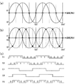
図5は、本発明の第1の実施形態に係る検出回路の動作を説明するための波形図である。図5において、横軸は、回転体の回転角θを表している。図5(a)には、図2に示す第1のセンサーユニット21の一方の出力信号A1によって表されるA相(SIN)の波形と、図3に示す第2のセンサーユニット22の一方の出力信号B1によって表されるB相(COS)の波形とが示されている。
FIG. 5 is a waveform diagram for explaining the operation of the detection circuit according to the first embodiment of the present invention. In FIG. 5, the horizontal axis represents the rotation angle θ of the rotating body. FIG. 5A shows the waveform of the A phase (SIN) represented by one output signal A1 of the
第1のセンサーユニット21の2つの出力信号A1及びA2を比較することにより、図5(c)に示す第1の検出信号D1が得られる。また、第2のセンサーユニット22の2つの出力信号B1及びB2を比較することにより、図5(c)に示す第2の検出信号D2が得られる。
By comparing the two output signals A1 and A2 of the
図5(b)には、図2に示す第1のセンサーユニット21の一方の出力信号A1の波形、及び、図3に示す第2のセンサーユニット22の一方の出力信号B1の波形に加えて、第1のセンサーユニット21の他方の出力信号A2の波形が破線で示されている。
In FIG. 5B, in addition to the waveform of one output signal A1 of the
第1のセンサーユニット21の一方の出力信号A1と第2のセンサーユニット22の一方の出力信号B1とを比較することにより、図5(c)に示す比較信号C1が得られる。また、第1のセンサーユニット21の他方の出力信号A2と第2のセンサーユニット22の一方の出力信号B1とを比較することにより、図5(c)に示す比較信号C2が得られる。さらに、比較信号C1と比較信号C2との排他的論理和を反転することにより、図5(c)に示す第3の検出信号D3が生成される。
By comparing one output signal A1 of the
図6は、第1〜第3の検出信号によって表される回転体の回転角を示す図である。図6に示すように、第1〜第3の検出信号D1〜D3の3ビットのデータによって、回転角180°内における8つの角度範囲を識別することができる。各角度範囲は、22.5°(1/16回転)となっている。図4に示す回転角算出回路36は、第1〜第3の検出信号D1〜D3に基づいて、回転体の回転角を表す回転角データを算出する。回転角データを単位時間において積分することにより、水道又はガスの使用量や、自転車等の速度を求めることが可能となる。
FIG. 6 is a diagram illustrating the rotation angle of the rotating body represented by the first to third detection signals. As shown in FIG. 6, eight angle ranges within a rotation angle of 180 ° can be identified by 3-bit data of the first to third detection signals D1 to D3. Each angle range is 22.5 ° (1/16 rotation). The rotation
再び図4を参照すると、センサー電源供給回路37は、図2に示す第1のセンサーユニット21、図3に示す第2のセンサーユニット22、及び、コンパレーター31〜34を含むアナログ回路に、センサー電源電位VSを供給する。ここで、センサー電源供給回路37は、システムクロック信号に同期して所定の期間だけセンサー電源電位VSをアナログ回路に供給することにより、アナログ回路を間欠駆動しても良い。センサー電源電位VSを供給する期間をシステムクロック信号の1周期よりも短くすることによって、アナログ回路において消費される電力を大幅に低減することができる。
Referring to FIG. 4 again, the sensor
本発明の第1の実施形態によれば、センサーユニット毎の2つの出力信号を比較することに加えて、第1のセンサーユニット21の一方の出力信号A1と第2のセンサーユニット22の一方の出力信号B1とを比較すると共に、第1のセンサーユニット21の他方の出力信号A2と第2のセンサーユニット22の一方の出力信号B1とを比較することにより、22.5°(1/16回転)の精度で磁界の回転角を検出することができる。
According to the first embodiment of the present invention, in addition to comparing two output signals for each sensor unit, one output signal A1 of the
次に、本発明の第2の実施形態に係る検出回路について説明する。
図7は、本発明の第2の実施形態に係る検出回路の構成を示す回路図である。この検出回路は、図1〜図3に示す磁気センサーに接続されて、磁気センサーと共に磁界回転角検出装置を構成する。
Next, a detection circuit according to a second embodiment of the present invention will be described.
FIG. 7 is a circuit diagram showing a configuration of a detection circuit according to the second embodiment of the present invention. This detection circuit is connected to the magnetic sensor shown in FIGS. 1 to 3 and constitutes a magnetic field rotation angle detection device together with the magnetic sensor.
図7に示すように、検出回路40は、第1の比較回路を構成するコンパレーター41と、第2の比較回路を構成するコンパレーター42〜43と、第2の比較回路における増幅部を構成するオペアンプ44〜47及び抵抗R9〜R14と、回転角算出回路48と、センサー電源供給回路49とを含んでいる。これらの回路は、半導体集積回路装置に内蔵されても良い。
As shown in FIG. 7, the
コンパレーター41は、図2に示す第1のセンサーユニット21の2つの出力信号A1及びA2を比較して、比較結果を表す第1の検出信号D1を出力する。第1の検出信号D1は、出力信号A1が出力信号A2よりも大きいときにハイレベルとなり、出力信号A1が出力信号A2よりも小さいときにローレベルとなる。
The
オペアンプ44及び46は、ボルテージフォロワーとして働き、図2に示す第1のセンサーユニット21の2つの出力信号A1及びA2をバッファーする。また、オペアンプ45及び47は、オペアンプ44及び46の出力信号A1及びA2を所定の増幅率で増幅して、振幅が同一で符号が互いに異なる第1の増幅信号C1及び第2の増幅信号C2をそれぞれ出力する。オペアンプ45及び47のオープンループゲインが十分大きい場合に、オペアンプ45の増幅率は、−R10/R9で与えられ、オペアンプ47の増幅率は、−R12/R11で与えられる。
The
あるいは、オペアンプ44及び46は、図2に示す第1のセンサーユニット21の2つの出力信号A1及びA2の内の一方をそれぞれ正相及び逆相で増幅することにより、振幅が同一で符号が互いに異なる第1の増幅信号C1及び第2の増幅信号C2を生成しても良い。
Alternatively, the
抵抗R13及びR14は、高電位側のセンサー電源電位VSと低電位側の電源電位とによって定まる電源電圧を分圧することにより、オペアンプ45及び47において用いられる基準電位VREFを生成する分圧回路を構成する。これにより、増幅信号の中点電位を、所望の基準電位VREFに近付けることができる。例えば、磁界が存在しない場合に、図2に示す第1のセンサーユニット21においてR1=R2かつR3=R4であり、図3に示す第2のセンサーユニット22においてR5=R6かつR7=R8である場合に、R13=R14とする。
The resistors R13 and R14 divide the power supply voltage determined by the sensor power supply potential V S on the high potential side and the power supply potential on the low potential side, thereby generating the reference potential V REF used in the
コンパレーター42は、図3に示す第2のセンサーユニット22の一方の出力信号B1と第1の増幅信号C1とを比較して、比較結果を表す第2の検出信号D2を出力する。第2の検出信号D2は、出力信号B1が増幅信号C1よりも大きいときにハイレベルとなり、出力信号B1が増幅信号C1よりも小さいときにローレベルとなる。
The
コンパレーター43は、第2のセンサーユニット22の一方の出力信号B1と第2の増幅信号C2とを比較して、比較結果を表す第3の検出信号D3を出力する。第3の検出信号D3は、出力信号B1が増幅信号C2よりも大きいときにハイレベルとなり、出力信号B1が増幅信号C2よりも小さいときにローレベルとなる。
The
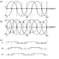
図8は、本発明の第2の実施形態に係る検出回路の動作を説明するための波形図である。図8において、横軸は、回転体の回転角θを表している。図8(a)には、図2に示す第1のセンサーユニット21の一方の出力信号A1によって表されるA相(SIN)の波形と、図3に示す第2のセンサーユニット22の一方の出力信号B1によって表されるB相(COS)の波形とが示されている。センサーユニット21の2つの出力信号A1及びA2を比較することにより、図8(c)に示す第1の検出信号D1が得られる。
FIG. 8 is a waveform diagram for explaining the operation of the detection circuit according to the second embodiment of the present invention. In FIG. 8, the horizontal axis represents the rotation angle θ of the rotating body. FIG. 8A shows the waveform of the A phase (SIN) represented by one output signal A1 of the
図8(b)には、A相(SIN)の波形及びB相(COS)の波形に加えて、第1のセンサーユニット21の2つの出力信号A1及びA2を所定の増幅率で増幅して得られる増幅信号C1及びC2の波形が一点鎖線で示されている。
In FIG. 8B, in addition to the A-phase (SIN) waveform and the B-phase (COS) waveform, the two output signals A1 and A2 of the
本実施形態においては、図3に示す第2のセンサーユニット22の一方の出力信号B1の電位と増幅信号C1及びC2の電位とが比較される。出力信号B1の振幅をBとすると、出力信号B1の電位は、次式で表される。
B1=−Bcos2θ
In the present embodiment, the potential of one output signal B1 of the
B1 = −Bcos2θ
また、増幅信号C1及びC2の振幅をCとすると、増幅信号C1及びC2の電位は、次式で表される。
C1=−Csin2θ
C2=Csin2θ
Further, assuming that the amplitudes of the amplified signals C1 and C2 are C, the potentials of the amplified signals C1 and C2 are expressed by the following equations.
C1 = −Csin2θ
C2 = Csin2θ
30°(1/12回転)の精度で回転体の回転角を検出するために、回転体の回転角θが30°であるときに、出力信号B1の電位と増幅信号C1の電位とが等しくなるように、図7に示すオペアンプ45の増幅率が設定される。
−Bcos60°=−Csin60°
∴B/C=sin60°/cos60°=tan60°=31/2
∴C=3−1/2B
従って、オペアンプ45の増幅率は、−3−1/2(約−0.6)となる。
In order to detect the rotation angle of the rotating body with an accuracy of 30 ° (1/12 rotation), when the rotation angle θ of the rotating body is 30 °, the potential of the output signal B1 is equal to the potential of the amplified signal C1. Thus, the amplification factor of the
-Bcos60 ° = -Csin60 °
∴ B / C = sin 60 ° / cos 60 ° = tan 60 ° = 3 1/2
∴C = 3 -1/2 B
Therefore, the amplification factor of the
また、回転体の回転角θが60°であるときに、出力信号B1の電位と増幅信号C2の電位とが等しくなるように、図7に示すオペアンプ47の増幅率が設定される。
−Bcos120°=Csin120°
∴B/C=−sin120°/cos120°=−tan120°=31/2
∴C=3−1/2B
従って、オペアンプ47の増幅率は、−3−1/2(約−0.6)となる。
Further, the amplification factor of the
-Bcos120 ° = Csin120 °
∴ B / C = −sin 120 ° / cos 120 ° = −tan 120 ° = 3 1/2
∴C = 3 -1/2 B
Therefore, the amplification factor of the
第2のセンサーユニット22の一方の出力信号B1と増幅信号C1とを比較することにより、図8(c)に示す第2の検出信号D2が生成される。また、第2のセンサーユニット22の一方の出力信号B1と第2の増幅信号C2とを比較することにより、図8(c)に示す第3の検出信号D3が生成される。
By comparing one output signal B1 of the
図9は、第1〜第3の検出信号によって表される回転体の回転角を示す図である。図9に示すように、第1〜第3の検出信号D1〜D3の3ビットのデータによって、180°内における6つの角度範囲を識別することができる。各角度範囲は、30°(1/12回転)となっている。図7に示す回転角算出回路48は、第1〜第3の検出信号D1〜D3に基づいて、回転体の回転角を表す回転角データを算出する。回転角データを単位時間において積分することにより、水道又はガスの使用量や、自転車等の速度を求めることが可能となる。
FIG. 9 is a diagram illustrating the rotation angle of the rotating body represented by the first to third detection signals. As shown in FIG. 9, six angle ranges within 180 ° can be identified by the 3-bit data of the first to third detection signals D1 to D3. Each angle range is 30 ° (1/12 rotation). The rotation
再び図7を参照すると、センサー電源供給回路49は、図2に示す第1のセンサーユニット21、図3に示す第2のセンサーユニット22、コンパレーター41〜43、及び、オペアンプ44〜47を含むアナログ回路に、センサー電源電位VSを供給する。ここで、センサー電源供給回路49は、システムクロック信号に同期して所定の期間だけセンサー電源電位VSをアナログ回路に供給することにより、アナログ回路を間欠駆動しても良い。センサー電源電位VSを供給する期間をシステムクロック信号の1周期よりも短くすることによって、アナログ回路において消費される電力を大幅に低減することができる。
Referring again to FIG. 7, the sensor
本発明の第2の実施形態によれば、第1のセンサーユニット21の2つの出力信号A1及びA2を比較することに加えて、第1のセンサーユニット21の出力信号A1及びA2を所定の増幅率で増幅して符号が互いに異なる第1の増幅信号C1及び第2の増幅信号C2を求め、第2のセンサーユニット22の出力信号B1又はB2と第1の増幅信号C1とを比較すると共に、第2のセンサーユニット22の出力信号B1又はB2と第2の増幅信号C2とを比較することにより、30°(1/12回転)の精度で磁界の回転角を検出することができる。
According to the second embodiment of the present invention, in addition to comparing the two output signals A1 and A2 of the
次に、本発明の第3の実施形態に係る検出回路について説明する。
図10は、本発明の第3の実施形態に係る検出回路の構成を示す回路図である。この検出回路は、本発明の第2の実施形態に係る検出回路を変形したものであり、同一の構成要素については重複する説明を省略する。
Next, a detection circuit according to a third embodiment of the present invention will be described.
FIG. 10 is a circuit diagram showing a configuration of a detection circuit according to the third embodiment of the present invention. This detection circuit is a modification of the detection circuit according to the second embodiment of the present invention, and redundant description of the same components will be omitted.
図10に示すように、検出回路40aは、第1の比較回路を構成するコンパレーター41と、第2の比較回路を構成するコンパレーター42〜43と、第2の比較回路における増幅部を構成するオペアンプ44〜45及び抵抗R9〜R10、R13〜R14とを含んでいる。これらの回路は、半導体集積回路装置に内蔵されても良い。
As shown in FIG. 10, the
オペアンプ44は、ボルテージフォロワーとして働き、図2に示す第1のセンサーユニット21の一方の出力信号A1をバッファーする。また、オペアンプ45は、オペアンプ44の出力信号A1を所定の増幅率で増幅して、増幅信号C1を出力する。
The
コンパレーター42は、図3に示す第2のセンサーユニット22の一方の出力信号B1と増幅信号C1とを比較して、比較結果を表す第2の検出信号D2を出力する。第2の検出信号D2は、出力信号B1が増幅信号C1よりも大きいときにハイレベルとなり、出力信号B1が増幅信号C1よりも小さいときにローレベルとなる。
The
コンパレーター43は、センサーユニット22の他方の出力信号B2と増幅信号C1とを比較して、比較結果を表す第3の検出信号D3を出力する。第3の検出信号D3は、出力信号B2が増幅信号C1よりも小さいときにハイレベルとなり、出力信号B2が増幅信号C1よりも大きいときにローレベルとなる。
The
図11は、本発明の第3の実施形態に係る検出回路の動作を説明するための波形図である。図11において、横軸は、回転体の回転角θを表している。図11(a)には、図2に示す第1のセンサーユニット21の一方の出力信号A1によって表されるA相(SIN)の波形と、図3に示す第2のセンサーユニット22の一方の出力信号B1によって表されるB相(COS)の波形とが示されている。センサーユニット21の2つの出力信号A1及びA2を比較することにより、図11(c)に示す第1の検出信号D1が得られる。
FIG. 11 is a waveform diagram for explaining the operation of the detection circuit according to the third embodiment of the present invention. In FIG. 11, the horizontal axis represents the rotation angle θ of the rotating body. FIG. 11A shows the waveform of the A phase (SIN) represented by one output signal A1 of the
図11(b)には、A相(SIN)の波形及びB相(COS)の波形に加えて、第2のセンサーユニット22の他方の出力信号B2の波形が破線で示され、第1のセンサーユニット21の一方の出力信号A1を所定の増幅率で増幅して得られる増幅信号C1の波形が一点鎖線で示されている。
In FIG. 11 (b), in addition to the waveform of the A phase (SIN) and the waveform of the B phase (COS), the waveform of the other output signal B2 of the
本実施形態においては、図3に示す第2のセンサーユニット22の2つの出力信号B1及びB2の電位と増幅信号C1の電位とが比較される。出力信号B1及びB2の振幅をBとすると、出力信号B1及びB2の電位は、次式で表される。
B1=−Bcos2θ
B2=Bcos2θ
また、増幅信号C1の振幅をCとすると、増幅信号C1の電位は、次式で表される。
C1=−Csin2θ
In the present embodiment, the potentials of the two output signals B1 and B2 of the
B1 = −Bcos2θ
B2 = Bcos2θ
When the amplitude of the amplified signal C1 is C, the potential of the amplified signal C1 is expressed by the following equation.
C1 = −Csin2θ
30°(1/12回転)の精度で回転体の回転角を検出するために、回転体の回転角θが30°であるときに、出力信号B1の電位と増幅信号C1の電位とが等しくなるように、図10に示すオペアンプ45の増幅率が設定される。
−Bcos60°=−Csin60°
∴B/C=sin60°/cos60°=tan60°=31/2
∴C=3−1/2B
従って、オペアンプ45の増幅率は、−3−1/2(約−0.6)となる。
In order to detect the rotation angle of the rotating body with an accuracy of 30 ° (1/12 rotation), when the rotation angle θ of the rotating body is 30 °, the potential of the output signal B1 is equal to the potential of the amplified signal C1. Thus, the amplification factor of the
-Bcos60 ° = -Csin60 °
∴ B / C = sin 60 ° / cos 60 ° = tan 60 ° = 3 1/2
∴C = 3 -1/2 B
Therefore, the amplification factor of the
また、回転体の回転角θが60°であるときに、出力信号B2の電位と増幅信号C1の電位とが等しくなるように、図10に示すオペアンプ45の増幅率が設定される。
Bcos120°=−Csin120°
∴B/C=−sin120°/cos120°=−tan120°=31/2
∴C=3−1/2B
従って、オペアンプ45の増幅率は、−3−1/2(約−0.6)となって、上記の増幅率と一致する。
Further, when the rotation angle θ of the rotating body is 60 °, the amplification factor of the
Bcos120 ° = −Csin120 °
∴ B / C = −sin 120 ° / cos 120 ° = −tan 120 ° = 3 1/2
∴C = 3 -1/2 B
Therefore, the amplification factor of the
第2のセンサーユニット22の一方の出力信号B1と増幅信号C1とを比較することにより、図11(c)に示す第2の検出信号D2が生成される。また、第2のセンサーユニット22の他方の出力信号B2と増幅信号C1とを比較することにより、図11(c)に示す第3の検出信号D3が生成される。第1〜第3の検出信号によって表される回転体の回転角は、図9に示すのと同様である。
By comparing one output signal B1 of the
本発明の第3の実施形態によれば、第1のセンサーユニット21の2つの出力信号A1及びA2を比較することに加えて、第1のセンサーユニット21の一方の出力信号A1を所定の増幅率で増幅して増幅信号C1を求め、第2のセンサーユニット22の一方の出力信号B1と増幅信号C1とを比較すると共に、第2のセンサーユニット22の他方の出力信号B2と増幅信号C1とを比較することにより、30°(1/12回転)の精度で磁界の回転角を検出することができる。
According to the third embodiment of the present invention, in addition to comparing the two output signals A1 and A2 of the
本発明は、以上説明した実施形態に限定されるものではなく、当該技術分野において通常の知識を有する者によって、本発明の技術的思想内で多くの変形が可能である。 The present invention is not limited to the embodiments described above, and many modifications can be made within the technical idea of the present invention by those having ordinary knowledge in the technical field.
10…回転体、10a…磁石、20…磁気センサー、21、22…センサーユニット、30、40、40a…検出回路、31〜34、41〜43…コンパレーター、35…論理回路、36、48…回転角算出回路、37、49…センサー電源供給回路、44〜47…オペアンプ、49…センサー電源供給回路、R1〜R8…MR素子、R9〜R14…抵抗
DESCRIPTION OF
Claims (6)
前記第1又は第2のセンサーユニットの出力信号を比較する第1の比較回路と、
前記第1のセンサーユニットの出力信号と前記第2のセンサーユニットの出力信号とを比較する第2の比較回路と、
前記第1の比較回路の比較結果と前記第2の比較回路の比較結果とに基づいて磁界の回転角を算出する回転角算出回路と、
を含み、
前記第1の比較回路が、前記第1のセンサーユニットの2つの出力信号を比較して、比較結果を表す第1の検出信号を出力する第1のコンパレーターを含み、
前記第2の比較回路が、
前記第1のセンサーユニットの出力信号を所定の増幅率で増幅して、振幅が同一で符号が互いに異なる第1の増幅信号及び第2の増幅信号を出力する増幅部と、
前記第2のセンサーユニットの出力信号と前記第1の増幅信号とを比較して、比較結果を表す第2の検出信号を出力する第2のコンパレーターと、
前記第2のセンサーユニットの出力信号と前記第2の増幅信号とを比較して、比較結果を表す第3の検出信号を出力する第3のコンパレーターと、
を含むことを特徴とする検出回路。 First sensor units and the detection circuit Tsu der the second sensor unit is connected to the magnetic sensor disposed at an angle to each other with a bridge circuit of the magnetoresistive element,
A first comparison circuit for comparing output signals of the first or second sensor unit;
A second comparison circuit for comparing the output signal of the first sensor unit and the output signal of the second sensor unit;
A rotation angle calculation circuit for calculating a rotation angle of a magnetic field based on a comparison result of the first comparison circuit and a comparison result of the second comparison circuit;
Including
The first comparison circuit includes a first comparator that compares two output signals of the first sensor unit and outputs a first detection signal representing a comparison result;
The second comparison circuit includes:
An amplifying unit for amplifying the output signal of the first sensor unit at a predetermined amplification factor, and outputting a first amplified signal and a second amplified signal having the same amplitude and different signs;
A second comparator that compares the output signal of the second sensor unit with the first amplified signal and outputs a second detection signal representing a comparison result;
A third comparator that compares the output signal of the second sensor unit with the second amplified signal and outputs a third detection signal representing a comparison result;
A detection circuit comprising:
前記第1又は第2のセンサーユニットの出力信号を比較する第1の比較回路と、
前記第1のセンサーユニットの出力信号と前記第2のセンサーユニットの出力信号とを比較する第2の比較回路と、
前記第1の比較回路の比較結果と前記第2の比較回路の比較結果とに基づいて磁界の回転角を算出する回転角算出回路と、
を含み、
前記第1の比較回路が、前記第1のセンサーユニットの2つの出力信号を比較して、比較結果を表す第1の検出信号を出力する第1のコンパレーターを含み、
前記第2の比較回路が、
前記第1のセンサーユニットの一方の出力信号を所定の増幅率で増幅して、増幅信号を出力する増幅部と、
前記第2のセンサーユニットの一方の出力信号と前記増幅信号とを比較して、比較結果を表す第2の検出信号を出力する第2のコンパレーターと、
前記第2のセンサーユニットの他方の出力信号と前記増幅信号とを比較して、比較結果を表す第3の検出信号を出力する第3のコンパレーターと、
を含むことを特徴とする検出回路。 First sensor units and the detection circuit Tsu der the second sensor unit is connected to the magnetic sensor disposed at an angle to each other with a bridge circuit of the magnetoresistive element,
A first comparison circuit for comparing output signals of the first or second sensor unit;
A second comparison circuit for comparing the output signal of the first sensor unit and the output signal of the second sensor unit;
A rotation angle calculation circuit for calculating a rotation angle of a magnetic field based on a comparison result of the first comparison circuit and a comparison result of the second comparison circuit;
Including
The first comparison circuit includes a first comparator that compares two output signals of the first sensor unit and outputs a first detection signal representing a comparison result;
The second comparison circuit includes:
An amplification unit that amplifies one output signal of the first sensor unit at a predetermined amplification rate and outputs an amplified signal;
A second comparator that compares one of the output signals of the second sensor unit with the amplified signal and outputs a second detection signal representing a comparison result;
A third comparator that compares the other output signal of the second sensor unit with the amplified signal and outputs a third detection signal representing a comparison result;
A detection circuit comprising:
前記磁気センサーと、
を含む磁界回転角検出装置。 The detection circuit according to any one of claims 1 to 3,
The magnetic sensor;
Magnetic field rotation angle detection device.
回転磁界を発生する回転体と、
を含む電子機器。 Magnetic field rotation angle detection device according to claim 5,
A rotating body that generates a rotating magnetic field;
Including electronic equipment.
Priority Applications (3)
| Application Number | Priority Date | Filing Date | Title |
|---|---|---|---|
| JP2013059601A JP6205774B2 (en) | 2013-03-22 | 2013-03-22 | Detection circuit, semiconductor integrated circuit device, magnetic field rotation angle detection device, and electronic device |
| US14/175,565 US9310448B2 (en) | 2013-03-22 | 2014-02-07 | Detection circuit, semiconductor integrated circuit device, magnetic field rotation angle detection device, and electronic device |
| CN201410108876.8A CN104062609B (en) | 2013-03-22 | 2014-03-21 | Detect circuit, conductor integrated circuit device, magnetic field rotating angle detecting device and electronic equipment |
Applications Claiming Priority (1)
| Application Number | Priority Date | Filing Date | Title |
|---|---|---|---|
| JP2013059601A JP6205774B2 (en) | 2013-03-22 | 2013-03-22 | Detection circuit, semiconductor integrated circuit device, magnetic field rotation angle detection device, and electronic device |
Publications (3)
| Publication Number | Publication Date |
|---|---|
| JP2014185884A JP2014185884A (en) | 2014-10-02 |
| JP2014185884A5 JP2014185884A5 (en) | 2016-01-07 |
| JP6205774B2 true JP6205774B2 (en) | 2017-10-04 |
Family
ID=51550412
Family Applications (1)
| Application Number | Title | Priority Date | Filing Date |
|---|---|---|---|
| JP2013059601A Active JP6205774B2 (en) | 2013-03-22 | 2013-03-22 | Detection circuit, semiconductor integrated circuit device, magnetic field rotation angle detection device, and electronic device |
Country Status (3)
| Country | Link |
|---|---|
| US (1) | US9310448B2 (en) |
| JP (1) | JP6205774B2 (en) |
| CN (1) | CN104062609B (en) |
Families Citing this family (11)
| Publication number | Priority date | Publication date | Assignee | Title |
|---|---|---|---|---|
| JP2016180727A (en) * | 2015-03-25 | 2016-10-13 | セイコーエプソン株式会社 | Detection circuit, semiconductor integrated circuit device, magnetic field rotation angle detection device, and electronic apparatus |
| US10591274B2 (en) * | 2016-09-28 | 2020-03-17 | Infineon Technologies Ag | External field robust angle sensing with differential magnetic field |
| DE102016118384B4 (en) * | 2016-09-28 | 2023-10-26 | Infineon Technologies Ag | Magnetic angle sensor device and method of operation |
| US10871381B2 (en) * | 2016-12-09 | 2020-12-22 | Tdk Corporation | Angle sensor and angle sensor system |
| US10533877B2 (en) * | 2017-02-17 | 2020-01-14 | Infineon Technologies Ag | Angle sensor with disturbance field suppression |
| CN111664778B (en) * | 2019-03-06 | 2021-10-26 | 英飞凌科技股份有限公司 | External field robust angle sensing using differential magnetic fields |
| US11608109B2 (en) | 2020-08-12 | 2023-03-21 | Analog Devices International Unlimited Company | Systems and methods for detecting magnetic turn counter errors with redundancy |
| US11493362B2 (en) | 2020-08-12 | 2022-11-08 | Analog Devices International Unlimited Company | Systems and methods for detecting magnetic turn counter errors |
| KR20220067698A (en) * | 2020-11-18 | 2022-05-25 | 주식회사 해치텍 | Contactless magnetic sensing system |
| CN113419197B (en) * | 2021-06-02 | 2022-02-15 | 华中科技大学 | Voltage-reducing magnetic flux ring device and magnetic flux induction signal measuring method |
| DE102021120034A1 (en) * | 2021-08-02 | 2023-02-02 | Infineon Technologies Ag | REDUNDANT CURRENT SENSOR |
Family Cites Families (25)
| Publication number | Priority date | Publication date | Assignee | Title |
|---|---|---|---|---|
| JPS6017364A (en) * | 1983-07-11 | 1985-01-29 | Fanuc Ltd | Detection for motor speed |
| JPS60161820U (en) * | 1984-04-05 | 1985-10-28 | 株式会社トーキン | magnetic rotary encoder |
| JP2558287B2 (en) * | 1987-07-29 | 1996-11-27 | 株式会社三協精機製作所 | Encoder device |
| US5012239A (en) * | 1989-08-21 | 1991-04-30 | Visa-Trak Corporation | High resolution position sensor circuit |
| JPH0760171B2 (en) | 1989-10-23 | 1995-06-28 | 愛知時計電機株式会社 | Magnetic field detection circuit |
| JPH08248056A (en) | 1995-03-08 | 1996-09-27 | Toshiba Corp | Rotation detector |
| JP2000180206A (en) * | 1998-12-21 | 2000-06-30 | Mitsubishi Electric Corp | Magnetism detecting device |
| JP2003202224A (en) * | 2001-12-28 | 2003-07-18 | Niles Parts Co Ltd | Rotation angle detector |
| WO2004113928A2 (en) * | 2003-06-25 | 2004-12-29 | Philips Intellectual Property & Standards Gmbh | Magnetic-field-dependant angle sensor |
| EP1751501A2 (en) * | 2004-05-14 | 2007-02-14 | Philips Intellectual Property & Standards GmbH | Sensor element and associated angle measurement system |
| JP4689435B2 (en) | 2004-12-16 | 2011-05-25 | アルプス電気株式会社 | Angle detection sensor |
| JP3848670B1 (en) | 2005-07-20 | 2006-11-22 | 株式会社トーメンエレクトロニクス | Rotation angle detector |
| US7714570B2 (en) * | 2006-06-21 | 2010-05-11 | Allegro Microsystems, Inc. | Methods and apparatus for an analog rotational sensor having magnetic sensor elements |
| JP2008134181A (en) * | 2006-11-29 | 2008-06-12 | Alps Electric Co Ltd | Magnetic detector and its manufacturing method |
| JP2009198316A (en) | 2008-02-21 | 2009-09-03 | Denso Corp | Rotation detection device |
| CN101629802A (en) * | 2008-07-14 | 2010-01-20 | Tdk株式会社 | Angle detecting apparatus and angle detecting method |
| JP5105201B2 (en) * | 2008-07-30 | 2012-12-26 | Tdk株式会社 | Angle detection apparatus and angle detection method |
| JP5306145B2 (en) | 2009-10-28 | 2013-10-02 | 旭化成エレクトロニクス株式会社 | Angle detection circuit and angle detection device |
| JP5096442B2 (en) * | 2009-11-17 | 2012-12-12 | 株式会社日立製作所 | Rotation angle measuring device, motor system and electric power steering system |
| JP2011237359A (en) * | 2010-05-13 | 2011-11-24 | Seiko Epson Corp | Device and method for detecting radio wave arrival angle |
| JP5110134B2 (en) * | 2010-08-30 | 2012-12-26 | Tdk株式会社 | Rotating magnetic field sensor |
| JP5566871B2 (en) * | 2010-12-15 | 2014-08-06 | 株式会社東海理化電機製作所 | Rotation detector |
| JP5800126B2 (en) | 2011-03-22 | 2015-10-28 | セイコーエプソン株式会社 | Pulse generation circuit, integrated circuit device, detection device |
| US9310240B2 (en) | 2011-03-22 | 2016-04-12 | Seiko Epson Corporation | Circuit device, integrated circuit and detection device |
| JP2012230021A (en) | 2011-04-27 | 2012-11-22 | Hitachi Automotive Systems Ltd | Rotation angle measuring device |
-
2013
- 2013-03-22 JP JP2013059601A patent/JP6205774B2/en active Active
-
2014
- 2014-02-07 US US14/175,565 patent/US9310448B2/en active Active
- 2014-03-21 CN CN201410108876.8A patent/CN104062609B/en active Active
Also Published As
| Publication number | Publication date |
|---|---|
| US20140285188A1 (en) | 2014-09-25 |
| US9310448B2 (en) | 2016-04-12 |
| JP2014185884A (en) | 2014-10-02 |
| CN104062609A (en) | 2014-09-24 |
| CN104062609B (en) | 2018-01-02 |
Similar Documents
| Publication | Publication Date | Title |
|---|---|---|
| JP6205774B2 (en) | Detection circuit, semiconductor integrated circuit device, magnetic field rotation angle detection device, and electronic device | |
| JP5105200B2 (en) | Angle detection apparatus and angle detection method | |
| US8378664B2 (en) | Arrangement comprising a magnetic-field-dependent angle sensor | |
| JP4646044B2 (en) | Magnetic detector | |
| TW201842299A (en) | Rotation angle detection device and rotation angle detection method | |
| JP5434850B2 (en) | Rotation angle / torque sensor | |
| JP2016050841A (en) | Magnetism detection device | |
| JP2012042353A (en) | Rotation angle and torque sensor | |
| Bhaskarrao et al. | A linear direct-digital converter for sinusoidal encoders | |
| JP6390608B2 (en) | Movement detector | |
| US20220196378A1 (en) | Magnetic sensor and sensor system | |
| JP2003287439A (en) | Rotation detecting device | |
| WO2015008472A1 (en) | Rotation sensor | |
| JP4805784B2 (en) | Position sensor | |
| JP5463851B2 (en) | Current sensor | |
| JP2012230021A (en) | Rotation angle measuring device | |
| JP5566871B2 (en) | Rotation detector | |
| JP5449417B2 (en) | Signal processing apparatus and rotation angle detection apparatus | |
| Karabeyli et al. | Enhancing the accuracy for the open-loop resolver to digital converters | |
| JP4213163B2 (en) | Magnetic detector | |
| JP2016180727A (en) | Detection circuit, semiconductor integrated circuit device, magnetic field rotation angle detection device, and electronic apparatus | |
| JP6291380B2 (en) | Non-contact rotation angle sensor | |
| JP6174393B2 (en) | Resolver excitation device | |
| JP2008268085A (en) | Rotary sensor | |
| JP2021135161A (en) | Rotation detection device |
Legal Events
| Date | Code | Title | Description |
|---|---|---|---|
| RD04 | Notification of resignation of power of attorney |
Free format text: JAPANESE INTERMEDIATE CODE: A7424 Effective date: 20150109 |
|
| A521 | Written amendment |
Free format text: JAPANESE INTERMEDIATE CODE: A523 Effective date: 20151113 |
|
| A621 | Written request for application examination |
Free format text: JAPANESE INTERMEDIATE CODE: A621 Effective date: 20151113 |
|
| A977 | Report on retrieval |
Free format text: JAPANESE INTERMEDIATE CODE: A971007 Effective date: 20160914 |
|
| A131 | Notification of reasons for refusal |
Free format text: JAPANESE INTERMEDIATE CODE: A131 Effective date: 20160927 |
|
| RD03 | Notification of appointment of power of attorney |
Free format text: JAPANESE INTERMEDIATE CODE: A7423 Effective date: 20160930 |
|
| RD04 | Notification of resignation of power of attorney |
Free format text: JAPANESE INTERMEDIATE CODE: A7424 Effective date: 20160930 |
|
| A521 | Written amendment |
Free format text: JAPANESE INTERMEDIATE CODE: A523 Effective date: 20161026 |
|
| A131 | Notification of reasons for refusal |
Free format text: JAPANESE INTERMEDIATE CODE: A131 Effective date: 20170314 |
|
| A521 | Written amendment |
Free format text: JAPANESE INTERMEDIATE CODE: A523 Effective date: 20170410 |
|
| TRDD | Decision of grant or rejection written | ||
| A01 | Written decision to grant a patent or to grant a registration (utility model) |
Free format text: JAPANESE INTERMEDIATE CODE: A01 Effective date: 20170808 |
|
| A61 | First payment of annual fees (during grant procedure) |
Free format text: JAPANESE INTERMEDIATE CODE: A61 Effective date: 20170821 |
|
| R150 | Certificate of patent or registration of utility model |
Ref document number: 6205774 Country of ref document: JP Free format text: JAPANESE INTERMEDIATE CODE: R150 |