JP2011229221A - Hermetic type electric compressor and refrigeration cycle device - Google Patents
Hermetic type electric compressor and refrigeration cycle device Download PDFInfo
- Publication number
- JP2011229221A JP2011229221A JP2010094592A JP2010094592A JP2011229221A JP 2011229221 A JP2011229221 A JP 2011229221A JP 2010094592 A JP2010094592 A JP 2010094592A JP 2010094592 A JP2010094592 A JP 2010094592A JP 2011229221 A JP2011229221 A JP 2011229221A
- Authority
- JP
- Japan
- Prior art keywords
- hermetic
- motor
- electric compressor
- conductive pins
- windings
- Prior art date
- Legal status (The legal status is an assumption and is not a legal conclusion. Google has not performed a legal analysis and makes no representation as to the accuracy of the status listed.)
- Pending
Links
Images


Landscapes
- Engineering & Computer Science (AREA)
- Mechanical Engineering (AREA)
- General Engineering & Computer Science (AREA)
- Compressor (AREA)
- Power Engineering (AREA)
- Windings For Motors And Generators (AREA)
- Motor Or Generator Frames (AREA)
- Physics & Mathematics (AREA)
- Thermal Sciences (AREA)
Abstract
Description
本発明は、DCブラシレスモータにより駆動される密閉形電動圧縮機に係り、または、HFC冷媒や自然系冷媒を用いた空気調和機,冷凍冷蔵庫,冷機応用製品,ヒートポンプ給湯機等の冷凍サイクル装置に好適なものである。 The present invention relates to a sealed electric compressor driven by a DC brushless motor, or to a refrigeration cycle apparatus such as an air conditioner, a refrigerator, a refrigerator application product, a heat pump water heater using an HFC refrigerant or a natural refrigerant. Is preferred.
DCブラシレスモータで駆動される密閉形電動圧縮機を搭載したルームエアコン等のシステムの省エネルギー化を図る際に、実使用での運転時間が多い低速条件での高効率化が重要な課題となっている。 When trying to save energy in a system such as a room air conditioner equipped with a hermetic electric compressor driven by a DC brushless motor, it is important to improve efficiency under low-speed conditions with a lot of operating time in actual use. Yes.
このような用途に適する技術として特許文献1が知られている。これによれば、図9を参照している段落〔0004〕には次のように記載されている。すなわち、「図9は、DCブラシレスモータの出力特性図であり、(a)は、トルク定数が大きいとき、即ち、巻線の巻数が多いときの出力特性を示し、(b)は、トルク定数が小さいとき、即ち、巻線の巻数が少ないときの出力特性を示している。図中、横軸は回転電機の回転数、縦軸は回転電機の出力をそれぞれ示し、実線で示される曲線は、同一効率点を結んだものであり、この図から明らかなように、トルク定数が大きく巻数が大きいときは、所定の低回転域に最高効率領域が存在し、トルク定数が小さく巻数が少ないときには所定の高回転域に最高効率領域が存在する。」とのことである。 Patent Document 1 is known as a technique suitable for such applications. According to this, the paragraph [0004] referring to FIG. 9 describes as follows. That is, “FIG. 9 is an output characteristic diagram of the DC brushless motor, (a) shows the output characteristic when the torque constant is large, that is, when the number of windings is large, and (b) shows the torque constant. In the figure, the horizontal axis represents the rotational speed of the rotating electrical machine, the vertical axis represents the output of the rotating electrical machine, and the curve indicated by the solid line represents the output characteristics when the number of windings is small. As shown in this figure, when the torque constant is large and the number of turns is large, the maximum efficiency region exists in the predetermined low rotation range, and when the torque constant is small and the number of turns is small. There is a maximum efficiency region in a predetermined high rotation region. "
一般的な機器の設計として、低速条件(あるいは高速条件)での効率を向上しようとすればモータの最高効率領域を低速条件(あるいは高速条件)に合わせて設計することになる。このような設計をした場合、高速条件(あるいは低速条件)ではモータの効率を最高効率領域では使用することができず、最悪の場合にはモータを駆動すること自体が困難となる。つまり、低速運転条件と高速運転条件の双方に適したモータを設計することは困難である。 As a general device design, if the efficiency under the low speed condition (or high speed condition) is to be improved, the maximum efficiency region of the motor is designed according to the low speed condition (or high speed condition). In such a design, the motor efficiency cannot be used in the highest efficiency region under the high speed condition (or low speed condition), and in the worst case, it is difficult to drive the motor itself. That is, it is difficult to design a motor that is suitable for both low-speed operation conditions and high-speed operation conditions.
そこで、従来より特許文献1のように、DCブラシレスモータの制御方式として、モータの固定子巻線を直列と並列で切り替える技術が提案されている。 Therefore, as in Patent Document 1, a technique for switching the stator windings of a motor in series and in parallel has been proposed as a control method for a DC brushless motor.
しかし、特許文献1には、固定子巻線が回転子の回転数の変化に応じて切替自在とされているものの、端子の具体的な配置や構成等については開示されていない。つまり、固定子巻線からの口出し線引き出し本数を増加させる必要があるものの、従来の密閉形電動圧縮機の構成では実現ができない。 However, Patent Document 1 does not disclose a specific arrangement or configuration of the terminals, although the stator winding can be switched in accordance with a change in the rotation speed of the rotor. That is, although it is necessary to increase the number of lead wires drawn out from the stator winding, it cannot be realized with the configuration of the conventional hermetic electric compressor.
本発明は、モータの固定子巻線を直列と並列とで切り替えることを可能とする具体的構成を密閉形電動圧縮機で実現することを目的とする。また、圧縮機回転数に対して、低速運転条件と高速運転条件の双方に適した冷凍サイクル装置を提供することを目的とする。 An object of this invention is to implement | achieve the concrete structure which makes it possible to switch the stator winding | coil of a motor in series and parallel with a hermetic type electric compressor. It is another object of the present invention to provide a refrigeration cycle apparatus suitable for both low-speed operation conditions and high-speed operation conditions with respect to the compressor rotation speed.
上記目的を達成するため本発明は、
密閉容器内に、圧縮機構部と、この圧縮機構部を駆動するためのDCブラシレスモータと、このモータの回転力を前記圧縮機構部に伝達するためのクランク軸とを備えた密閉形電動圧縮機において、
前記モータに給電を行う導電ピンを9本有することを特徴とする。
In order to achieve the above object, the present invention
A hermetic electric compressor having a compression mechanism part, a DC brushless motor for driving the compression mechanism part, and a crankshaft for transmitting the rotational force of the motor to the compression mechanism part in the hermetic container In
It has nine conductive pins for supplying power to the motor.
また、上記目的を達成するため本発明は、
密閉容器内に、圧縮機構部と、この圧縮機構部を駆動するためのDCブラシレスモータと、このモータの回転力を前記圧縮機構部に伝達するためのクランク軸とを備えた密閉形電動圧縮機において、
前記モータに給電を行う9本の導電ピンと、
前記密閉容器内に配設され、前記モータの巻線を構成する6つの巻線と、を備え、
前記6つの巻線のうちの3つの巻線の各一端を、前記9本の導電ピンのうち3つの導電ピンと接続し、前記密閉容器内で当該3つの巻線の他端を1つに接続して中性点を構成し、
残りの6つの導電ピンのうち2つずつを残りの3つの各巻線で接続した
ことを特徴とする。
In order to achieve the above object, the present invention
A hermetic electric compressor having a compression mechanism part, a DC brushless motor for driving the compression mechanism part, and a crankshaft for transmitting the rotational force of the motor to the compression mechanism part in the hermetic container In
9 conductive pins for supplying power to the motor;
6 windings disposed in the sealed container and constituting windings of the motor,
One end of each of the three windings of the six windings is connected to three of the nine conductive pins, and the other end of the three windings is connected to one in the sealed container. And configure a neutral point,
Two of the remaining six conductive pins are connected by the remaining three windings.
本発明によれば、モータの固定子巻線を直列と並列とで切り替えることを可能とする密閉形電動圧縮機を実現することができる。また、圧縮機回転数に対して、低速運転条件と高速運転条件の双方に適した冷凍サイクル装置を提供することができる。 ADVANTAGE OF THE INVENTION According to this invention, the hermetic type electric compressor which makes it possible to switch the stator winding | coil of a motor with series and parallel is realizable. Further, it is possible to provide a refrigeration cycle apparatus suitable for both the low speed operation condition and the high speed operation condition with respect to the compressor rotation speed.
以下、本発明に係る密閉形電動圧縮機の実施の形態を、図を用いて説明する。各図における同一符号は同一物または相当物を示す。 Hereinafter, embodiments of a hermetic electric compressor according to the present invention will be described with reference to the drawings. The same reference numerals in the drawings indicate the same or equivalent.
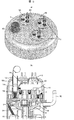
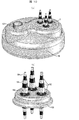
図1は本発明の一実施例に係る密閉形電動圧縮機の蓋体1Bを示す斜視図である。図2は図1に示す圧縮機の縦断面図である。本実施の形態は、図1,図2に示すような密閉形のスクロール圧縮機であるが、これは一例として示すものであり、スクロール圧縮機だけに限定するものではなく、他の圧縮機でも構わない。
FIG. 1 is a perspective view showing a
密閉容器1は、筒体1A,蓋体1B,底体1Cにて構成される。この密閉容器1内に溶接や焼き嵌め等でフレーム9を固定し、クランク軸6の支持部材とする。こちらを主軸受支持部材と称する。
The sealed container 1 includes a
クランク軸6の下端は密閉容器1の下部の油溜めに達して、密閉容器1内に溶接や焼き嵌めして固定された副軸受支持部材11と、この副軸受支持部材11に溶接やボルト止めされた副軸受12に軸支される。
The lower end of the
これらによって、クランク軸6は安定して回転することができる。
As a result, the
フレーム9と、このフレーム9上にボルト止めした固定スクロール7との間に、旋回スクロール8を挟みこんでスクロール式の圧縮機構部2を構成する。旋回スクロール8の渦巻と固定スクロール7の渦巻とは互いに噛み合っている。旋回スクロール8はクランク軸6によって駆動される。詳しくは、クランク軸6の偏心部が旋回スクロール8の渦巻の裏面に嵌合しており、自転運動せずに公転運動を行うよう円軌道運動する。旋回スクロール8とフレーム9との間に設けられたオルダムリング10等(オルダムリング10のキーと、旋回スクロール8のキー溝と、フレーム9のキー溝)による自転防止機構によって旋回スクロール8の自転が防止される。
The scroll-type compression mechanism 2 is configured by sandwiching the
クランク軸6の上端にある旋回軸部を旋回スクロール8に設けた旋回軸受に嵌合させ、偏心駆動することにより旋回スクロール8を円軌道運動させ、これにより固定スクロール7の渦巻と旋回スクロール8の渦巻とで形成している圧縮室が、外周側から中央部に移動しながら、その容積を小さくしている。
The orbiting shaft portion at the upper end of the
これを利用して、密閉容器1外に通じた吸込パイプ1D及び固定スクロール7の上部の吸入口7Aから冷媒ガスを吸入して圧縮していく。所定圧力以上になった冷媒ガスは固定スクロール7の中央部の吐出口7Bから密閉容器1内に吐出される。
Utilizing this, the refrigerant gas is sucked and compressed from the suction pipe 1 </ b> D leading to the outside of the sealed container 1 and the suction port 7 </ b> A at the top of the fixed scroll 7. The refrigerant gas that has reached a predetermined pressure or higher is discharged into the sealed container 1 from the
密閉容器1内は吐出圧の冷媒で満たされる、いわゆる高圧チャンバタイプの圧縮機である。密閉容器1内の冷媒は、吐出パイプ1Eより接続されるサイクルへと吐出される。そして冷凍サイクル内を循環し、吸込パイプ1Dに戻ってきて、以上を繰り返す。
The hermetic container 1 is a so-called high-pressure chamber type compressor that is filled with a refrigerant having a discharge pressure. The refrigerant in the sealed container 1 is discharged to a cycle connected from the
クランク軸6はモータにより回転される。モータの固定子3は、前記圧縮機構部2と副軸受支持部材11の間に位置して、溶接や焼き嵌め等で密閉容器1に固定されている。モータの回転子4は、クランク軸6に焼き嵌めや圧入により固定されている。これら固定子3と回転子4とによりモータが構成されている。
The
回転子4の上下端部にはピン4Bにより止め付けられたバランスウエイト4Aが設けられ、これにより回転子4及びクランク軸6が安定して回転し、旋回スクロール8を安定して円軌道運動させることができる。
回転子4は、鋼板を積層した回転子鉄心4Cの内部に永久磁石(図示せず)を4箇所内蔵した構成とし、固定子3は、鋼板を積層した固定子鉄心3Bに6個のティース(図示せず)とそれらをつなぐヨーク(図示せず)とからなり、各ティースの間に内方及び上下方に開放した6個のスロット(図示せず)が形成されている。
The rotor 4 has a configuration in which four permanent magnets (not shown) are built in a
各ティースの径方向の内方の先端は、周知の如く、回転子4の外周面に沿うように拡開されたティース先端部が形成されている。上記スロットは、固定子巻線3Cを収納するためのものである。絶縁紙(図示せず)を介して各ティースにスロット(図示せず)の空間を利用して、2組のU相,V相,W相の固定子巻線3Cを直接巻回することにより、いわゆる集中巻方式によって固定子3の磁極を形成し、4極6スロットのモータを構成している。 As is well known, the distal end of each tooth in the radial direction is formed with a tooth distal end portion that is expanded along the outer peripheral surface of the rotor 4. The slot is for accommodating the stator winding 3C. By directly winding two sets of U-phase, V-phase, and W-phase stator windings 3C on each tooth through insulating paper (not shown) using a slot (not shown) space. The magnetic poles of the stator 3 are formed by a so-called concentrated winding method to constitute a 4-pole 6-slot motor.
なお、3Aは口出し線であり、モータに電力を与えるための線である。この口出し線3Aは、密閉容器1の外部の電源と接続するためのハーメチックターミナル5に接続される。接続はコネクタであるクラスタ3Dによって行われる。
In addition, 3A is a lead wire and is a wire for supplying electric power to the motor. This lead wire 3 </ b> A is connected to a
固定子巻線から口出し線3Aを圧縮機構部2側へ9本引き出し、密閉容器1の筒体1Aとフレーム9と固定スクロール7に設けた口出し線3A誘導溝(図示せず)を通して圧縮機構部2の上方へ導き、蓋体1Bに設置したハーメチックターミナル5の導電ピン5Aにそれぞれ接続する。この導電ピン5Aからモータへの給電が行われる。
Nine
図3(a)に従来の並列接続の固定子巻線3Cの接続図、図3(b)に本発明の実施例の直列、並列切り替え用固定子巻線3Cの接続図を示す。 FIG. 3A shows a connection diagram of the conventional stator winding 3C connected in parallel, and FIG. 3B shows a connection diagram of the series / parallel switching stator winding 3C of the embodiment of the present invention.
図3(a)に示す従来の形態では、独立な巻線が6つあり、黒丸で表される中性点1xに対して、第1の各巻線(U2,V2,W2)と第2の各巻線(U1,V1,W1)との、2つの巻線の各組(U1,U2),(V1,V2),(W1,W2)がそれぞれ並列に接続され、それぞれU相,V相,W相を構成している。モータの口出し線3Aは、U相,V相,W相の各相から1本ずつの3本となる。
In the conventional form shown in FIG. 3 (a), there are six independent windings, and the first windings (U2, V2, W2) and the second winding with respect to the
図3(b)に示す本発明の実施例では、独立な巻線が6つあり、3つの巻線が単独で中性点1xに接続されている(U2,V2,W2)。これを第1の各巻線と称することとする。これらとは別に、中性点1xに接続されない巻線(U1,V1,W1)がある。これを第2の各巻線と称することとする。このそれぞれの各巻線(U2,V2,W2)と(U1,V1,W1)とは対を成している。これら中性点1xに接続される第1の巻線群と中性点に接続されない第2の巻線群とが、巻線切替装置30(図4)により並列または直列に接続される。これら何れかの接続構成によって圧縮機が駆動されることになる。
In the embodiment of the present invention shown in FIG. 3B, there are six independent windings, and three windings are independently connected to the
直列,並列切り替え用モータの口出し線3Aは、U相,V相,W相の各相から5A1〜5A3,5A4〜5A6,5A7〜5A9というように、3本ずつ引き出す必要が有り、合計9本必要となる。
The
そこで、本実施例の密閉形電動圧縮機は、蓋体1Bを図1,図2のように球形状とし、3つの導電ピン5Aを具備したハーメチックターミナル5を3つ設置した構成としている。本実施例では、蓋体1Bは今までと同様の形状なので、直ぐに適用可能であり、既存の組み立てにプラスアルファでハーメチックターミナル5を設置するだけでよい。なお、従来のハーメチックターミナル5を1つ設置した蓋体1Bに対し、ハーメチックターミナル5を3つ設置した本実施例の蓋体1Bは、蓋体1Bを球形状とされていることで、蓋体1Bに繰り返し作用する圧力への耐力を確保している。
Therefore, the hermetic electric compressor of this embodiment has a configuration in which the
図4に、本実施例のシステム構成図の一例を示す。 FIG. 4 shows an example of a system configuration diagram of this embodiment.
密閉形電動圧縮機はインバータ20によって回転数が制御される。また、リレーによって動作する巻線切替装置30を備え、インバータ20と圧縮機との間に配設することで、巻線切替装置30により運転条件に応じて圧縮機のモータの固定子巻線3Cを直列と並列に切り替える。巻線切替装置30は、圧縮機との組み合わせによって、その内部に中性点30xを構成することができる仕組みを備えている。巻線切替装置30の中身としての当該仕組みを着想し、構成することは当業者であれば何らの困難もなく可能な業である。
The rotational speed of the hermetic electric compressor is controlled by the
その切り替えは、制御装置50によって行われる。図中波線で表す制御装置50からの信号により、巻線切替装置30内のリレーを切り替えて、内部に中性点を構成するかしないかを制御する。制御装置50は、例えば、収集したモータ回転数情報に基づいて巻線切替装置30を制御することによって、固定子巻線の直列接続と並列接続との切り替えを制御する。また別の例としては制御装置50は、モータの出力−回転数に基づく効率のマップデータを保持しており、当該マップデータに基づいて、切り替えを制御する。
The switching is performed by the
導電ピン5Aは、5A1〜5A9というように、密閉容器1から9本出ている。どの3本を1つに纏めて1つのターミナル5とするかは適宜決定すればよい。例えば、(5A1−5A4−5A7),(5A2−5A5−5A8),(5A3−5A6−5A9)というように、1つのターミナルにU,V,Wを1つずつ配置した構成とする。こうすれば直感的に分かりやすい。また例えば、(5A1−5A2−5A3),(5A4−5A5−5A6),(5A7−5A8−5A9)というように、1つのターミナルは全てU相、別の1つのターミナルは全てV相、更に別の1つのターミナルは全てW相のように配置した構成とする。このようにしても直感的に分かりやすい。何れにせよ、巻線切替装置30側との関係でどうすればよいか決めれば良いが、ピンの数が増えるので分かりやすくすることが重要である。
Nine
また、圧縮機と、図中上側の第一熱交換器100と、下側の第二熱交換器200と、その間に配設された減圧装置150とで冷凍サイクルを構成している。なお、再熱除湿を行う場合には、例えば第一熱交換器100を室内機内に配設し、第一熱交換器100を2つに分割してその間に絞り装置を配設する。
Further, the compressor, the
(a)は固定子巻線3Cを並列接続とする構成図、(b)は固定子巻線3Cを直列接続とする構成図を示す。 (A) is a block diagram in which the stator winding 3C is connected in parallel, and (b) is a block diagram in which the stator winding 3C is connected in series.
直列の際は、U1とU2とが文字通り直列となる。V,Wについても同様である。これに対し、並列の場合は図3(a)で図示するようなものとは異なる。 In series, U1 and U2 are literally in series. The same applies to V and W. On the other hand, the parallel case is different from that shown in FIG.
図3(a)の並列接続では、黒丸が一つしか表現されていないが、これは第1の各巻線(U2,V2,W2)の中性点1xと、第2の各巻線(U1,V1,W1)の中性点1xとを一致させて表している。
In the parallel connection of FIG. 3 (a), only one black circle is represented. This is because the
一方の図4(a)の並列接続では、一つの中性点1xは密閉容器1の中心の黒丸で示している。これがモータの構成の中で設置した中性点1xである。もう一つの中性点は巻線切替装置30内に回路構成上に形成された中性点30xである。従って、二つの中性点が一致していないが、図3(a)と同様の並列接続の構成となる。
On the other hand, in the parallel connection shown in FIG. 4A, one
このように、9本の導電ピンと、モータの巻線を構成する6つの巻線とを備えて以下のように構成する。すなわち、6つの巻線のうちの3つの巻線(U2,V2,W2)の各一端を、3つの導電ピン(図では5A3,5A6,5A9)と接続し、密閉容器内で当該3つの巻線の他端を1つに接続して中性点1xを構成するとともに、残りの6つの導電ピン(図では5A1,5A4,5A7,5A2,5A5,5A8)のうち2つずつ(図では5A1−5A2,5A4−5A5,5A7−5A8)を残りの3つの各巻線(U1,V1,W1)で接続する。
In this way, nine conductive pins and six windings constituting the winding of the motor are provided and configured as follows. That is, one end of each of the three windings (U2, V2, W2) of the six windings is connected to three conductive pins (5A3, 5A6, 5A9 in the figure), and the three windings are sealed in a sealed container. The other end of the line is connected to one to form a
以上のように、インバータ20と圧縮機との間に巻線切替装置30を設けることで、巻線切替装置30により運転条件に応じて圧縮機のモータの固定子巻線3Cを直列と並列に切り替えることができる。
As described above, by providing the winding
固定子3の巻線の巻数をnとすると、(a)の並列接続では一相当りの巻数Npはnとなり、(b)の直列接続では一相当りの巻数Nsは2nとなる。添え字のpは並列、sは直列の頭文字である。以下でも同様である。トルク定数は一相当りの巻数に比例するので、直列接続時のトルク定数Ktsは、並列接続時のトルク定数Ktpの2倍となる。また、並列接続時および直列接続時において、トルクTを得るために必要な電流をそれぞれIpおよびIsとすると、電流Ip,Isは、数式(1),(2)により求められる。 When n is the number of windings of the stator 3, the equivalent number of turns Np is n in the parallel connection of (a), and the equivalent number of turns Ns is 2n in the series connection of (b). The subscript p is parallel and s is serial acronym. The same applies to the following. Since the torque constant is proportional to the number of turns corresponding to one, the torque constant Kts at the time of series connection is twice the torque constant Ktp at the time of parallel connection. Further, when the currents necessary for obtaining the torque T during parallel connection and series connection are Ip and Is, respectively, the currents Ip and Is can be obtained by equations (1) and (2).
Ip=T/Ktp=T/(Kts/2)=2Is …(1)
Is=T/Kts …(2)
また、一つの巻線の抵抗をrとし、並列接続時および直列接続時の抵抗をRpおよびRsとすると、数式(3),(4)に示すようになる。
Ip = T / Ktp = T / (Kts / 2) = 2Is (1)
Is = T / Kts (2)
Further, when the resistance of one winding is r and the resistances in parallel connection and series connection are Rp and Rs, the following equations (3) and (4) are obtained.
Rp=r/2 …(3)
Rs=2r …(4)
従って、並列接続時および直列接続時の銅損PcpおよびPcsは、数式(5),(6)のようになる。
Rp = r / 2 (3)
Rs = 2r (4)
Therefore, the copper losses Pcp and Pcs at the time of parallel connection and at the time of series connection are as shown in equations (5) and (6).
Pcp=Ip2Rp=(2Is)2r/2=2Is2r …(5)
Pcs=Is2Rs=2Is2r …(6)
以上のように、巻線を切り替えても銅損は変化せず、一つの相に流れる電流は、(b)の直列接続の場合は、(a)の並列接続の場合の1/2となる。
Pcp = Ip 2 Rp = (2Is) 2 r / 2 = 2Is 2 r (5)
Pcs = Is 2 Rs = 2Is 2 r (6)
As described above, the copper loss does not change even when the windings are switched, and the current flowing in one phase is ½ in the case of (b) in the series connection and in the case of the parallel connection in (a). .
従って、横軸を圧縮機の回転数(つまりモータ回転数)とし、縦軸を出力とした場合、回転数に対する出力は2つの山を持ち、等高線で表すと図12のようになる。左側の斜線領域Lが低速回転での高効率領域、右側の斜線領域Hが高速回転での高効率領域を表している。 Therefore, when the horizontal axis is the compressor rotation speed (that is, the motor rotation speed) and the vertical axis is the output, the output with respect to the rotation speed has two peaks and is represented by contour lines as shown in FIG. The left hatched area L represents a high efficiency area at low speed rotation, and the right hatched area H represents a high efficiency area at high speed rotation.
つまり、低速条件での効率を向上しようとしてモータの最高効率領域を低速条件に合わせて設計するとしても、この場合には直列接続で設計し、高速条件では並列接続とすればモータの効率を最高効率領域で使用することができる。 In other words, even if the maximum efficiency region of the motor is designed in accordance with the low speed condition in order to improve the efficiency under the low speed condition, in this case, the motor efficiency is maximized by the series connection and the parallel connection under the high speed condition. Can be used in the efficiency area.
また、直列接続にした場合、前述のように、並列接続の場合に比して、モータの電流が1/2となるため、駆動するインバータ20の効率が改善され、システムとしての効率を向上することができる。
In addition, when connected in series, as described above, since the motor current is halved compared to the case of parallel connection, the efficiency of the
このように、モータの固定子巻線を直列と並列とで切り替えることを可能とすることができる。また、低速回転の場合に直列接続とし、高速回転の場合に並列接続とすることで、圧縮機回転数に対して、低速運転条件と高速運転条件の双方に適した圧縮機を実現することが可能となる。延いては、低速運転条件と高速運転条件の双方に適した、つまり双方で効率の高い冷凍サイクル装置を提供することができる。 In this way, the stator windings of the motor can be switched between series and parallel. In addition, by connecting in series in the case of low speed rotation and in parallel connection in the case of high speed rotation, it is possible to realize a compressor suitable for both low speed operation conditions and high speed operation conditions with respect to the compressor rotation speed. It becomes possible. As a result, it is possible to provide a refrigeration cycle apparatus that is suitable for both low-speed operation conditions and high-speed operation conditions, that is, both are highly efficient.
低速・高速を別の表現にすれば、モータの所定回転数で切り替えるということになる。当該切り替えに当たっては、例えば、ルームエアコンでは、低速を4,000rpm以下、高速を3,000rpm以上として重なりを持たせれば無用な切り替えを低減して全体最適とすることができる。また前述の効率マップデータに関して、ルームエアコンの場合には、基本的な運転モードが冬期定格条件,冬期中間条件,夏期定格条件,夏期中間条件というように4つある。定格条件では高速運転,中間条件では低速運転と対応付けることができるので、斯様に切り替えても良い。 If the low speed and the high speed are expressed differently, it is switched at a predetermined number of rotations of the motor. In the switching, for example, in a room air conditioner, if the low speed is set to 4,000 rpm or less and the high speed is set to 3,000 rpm or more to provide an overlap, unnecessary switching can be reduced and the whole can be optimized. Regarding the efficiency map data described above, in the case of a room air conditioner, there are four basic operation modes, such as winter rated conditions, winter intermediate conditions, summer rated conditions, and summer intermediate conditions. Since the rated conditions can be associated with high-speed operation, and the intermediate conditions can be associated with low-speed operation, it may be switched in this way.
ルームエアコンは、ほぼ常時運転とも言うことができ、年間を通じて運転されるため、その使用環境が大きく変わる。そのため年間消費効率APFという指標によって評価される。ルームエアコンの場合には所定回転数,運転モードの何れで切り替えるにせよ、省エネの点で非常に有効である。 The room air conditioner can be said to be almost always operated, and it is operated throughout the year, so its usage environment changes greatly. Therefore, it is evaluated by an index called annual consumption efficiency APF. In the case of a room air conditioner, switching between the predetermined rotation speed and the operation mode is very effective in terms of energy saving.
他に同様の機器としてヒートポンプ給湯機,冷蔵庫等も該当する。ヒートポンプ給湯機であれば沸き上げモード時には高速運転、保温モード時には低速運転として切り替えたり、冷蔵庫であればドアの開閉のない夜間は温度を一定に保つだけの低速モード、昼間はドアの開閉があるので庫内温度が一定になるまで冷やす高速モードとして切り替えてやれば良い。これらは、洗濯機や掃除機など使用環境が変わらないような機器とは異なり、つまり単なる所定回転数、運転モードで直並列を切り替えるというのとは異なる。 Other similar devices include heat pump water heaters and refrigerators. If it is a heat pump water heater, it switches to high speed operation in the boiling mode and low speed operation in the heat insulation mode, or if it is a refrigerator, it has a low speed mode that keeps the temperature constant at night without door opening and closing, and it opens and closes the door in the daytime Therefore, it may be switched as a high-speed mode for cooling until the inside temperature becomes constant. These are different from devices that do not change the usage environment such as washing machines and vacuum cleaners, that is, different from simply switching between series and parallel at a predetermined rotation speed and operation mode.
以上の構成は、DCブラシレスモータにより駆動される密閉形電動圧縮機を搭載したあらゆる機器に適用が可能である。 The above configuration can be applied to all devices equipped with a hermetic electric compressor driven by a DC brushless motor.
図5は、本発明の一実施例に係る密閉形電動圧縮機の蓋体1Bの斜視図である。
FIG. 5 is a perspective view of the
基本的には実施例1にて説明した通りである。実施例1(図1)にて説明した、蓋体1Bを球形状として、ハーメチックターミナル5を3つ設置した構成の場合、ハーメチックターミナル5の導電ピン5Aがそれぞれ蓋体1Bの球面に沿った形で、蓋体1Bの中心から外周側へ傾いた形で設置されるため、圧縮機組立工程における着磁や商用試験等の工程の設備改造が大掛かりとなる。
Basically, it is as described in the first embodiment. In the configuration described in the first embodiment (FIG. 1), in which the
また、従来の蓋体1Bに対してハーメチックターミナル5が2つ増えることとなるので剛性が低下し、繰り返し作用する圧力への耐力が低下することが懸念される。
Moreover, since two
そこで、第2の実施例では、蓋体1Bを、上面が平坦の形状とし、蓋体1B自体の板厚を従来の板厚に対し27%以上厚くした構成とし、ハーメチックターミナル5の設置面をクランク軸6方向に対して直角にし、ハーメチックターミナル5の導電ピン5Aが、それぞれクランク軸6の方向に平行になるようにしたものである。ハーメチックターミナル5を2つ増やしても蓋体1Bの強度が弱くならないように、周面1Aとの板厚比では従来1.1程度だったものを、1.4程度以上にして、強度を確保する。前述の27%は1.4/1.1である。
Therefore, in the second embodiment, the
本構成とすることで、クラスタ3Dの取り付けが容易となり組み立て上、好ましい。また、蓋体1Bの圧力に対する耐力を確保しつつ、着磁や商用試験等の工程の設備改造を軽減できる。また、簡単な形状であるため、蓋体1Bのプレスの型製作及び工程も容易となる。
This configuration is preferable in terms of assembly because the
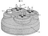
図6は、本発明の一実施例に係る密閉形電動圧縮機の蓋体1Bの斜視図である。
FIG. 6 is a perspective view of the
基本的には実施例1にて説明した通りである。実施例1(図1)にて説明した、蓋体1Bを球形状として、ハーメチックターミナル5を3つ設置した構成の場合、ハーメチックターミナル5の導電ピン5Aがそれぞれ蓋体1Bの球面に沿った形で、蓋体1Bの中心から外周側へ傾いた形で設置されるため、圧縮機組立工程における着磁や商用試験等の工程の設備改造が大掛かりとなる。
Basically, it is as described in the first embodiment. In the configuration described in the first embodiment (FIG. 1), in which the
そこで、第3の実施例では、蓋体1Bを、球形状をベースとし、そこから張り出した平面を設けることで、ハーメチックターミナル5の設置面を設けることとした。この設置面をクランク軸6方向に対して直角として、ハーメチックターミナル5の導電ピン5Aが、それぞれクランク軸6方向に平行になるようにしたものである。
Therefore, in the third embodiment, the
本構成とすることで、クラスタ3Dの取り付けが容易となり組み立て上、好ましい。また、蓋体1Bの圧力に対する耐力を張り出し部分で剛性を向上して確保しつつ、着磁や商用試験等の工程の設備改造を少なからず軽減できる。
This configuration is preferable in terms of assembly because the
図7に本発明の一実施例に係る密閉形電動圧縮機の蓋体1Bの斜視図を示す。
FIG. 7 is a perspective view of the
基本的には実施例1にて説明した通りである。本実施例の密閉形電動圧縮機は、実施例2と同様に、蓋体1Bを球形状をベースとし、ハーメチックターミナル5の設置面をクランク軸6方向に対して直角にし、ハーメチックターミナル5の導電ピン5Aが、それぞれクランク軸6方向に平行になるようにしたもので、且つ、ハーメチックターミナル5の導電ピン5Aを、4本のものを1つと、5本のものを1つと、を組み合わせた構成である。
Basically, it is as described in the first embodiment. As in the second embodiment, the hermetic electric compressor of the present embodiment is based on the spherical shape of the
実施例1,2では、口出し線3Aの端子をクラスタ3Dとしているので3ヶ所接続する必要があるが、本構成により、これを2箇所とすることができるため、3箇所接続の場合に対して組み立て時の作業性が向上する。
In the first and second embodiments, since the terminal of the
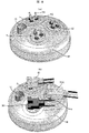
図8(a)(b)に本発明の一実施例に係る密閉形電動圧縮機の蓋体1Bの斜視図を示す。
FIGS. 8A and 8B are perspective views of the
基本的には実施例1にて説明した通りである。本実施例の密閉形電動圧縮機は、実施例1と同様に、蓋体1Bを球形状をベースとした形状とし、3本の導電ピン5Aを具備するハーメチックターミナル5を3つ設置した構成としている。
Basically, it is as described in the first embodiment. As in the first embodiment, the hermetic electric compressor of the present embodiment has a configuration in which the
この3つのハーメチックターミナル5に対して、クラスタ3Dを(白・黒・灰)などの視認性の良い3色で構成すると誤接続を回避することができる。
For the three
また、別の工夫としては、二つのクラスタを色違いとし、他の1つの大きさを異ならせる方法もある。これについて、以下説明する。 As another contrivance, there is a method in which two clusters have different colors and the other one has a different size. This will be described below.
3つのハーメチックターミナルの内、1つのハーメチックターミナル5の導電ピン5Aの径を、他の2つのハーメチックターミナル5の導電ピン5Aの径と異なる径としている。図8では、吸込パイプ1Dから最も遠いターミナル5(z)の導電ピンを他のターミナル5の導電ピン5Aの径とは異ならせ、太くしている。
Of the three hermetic terminals, the diameter of the
固定子3からの口出し線3Aとハーメチックターミナル5の接続(密閉容器1内での接続)、及び、巻線切替装置30からの配線とハーメチックターミナル5の接続(密閉容器1外での接続)にクラスタを使用する場合に、2つの導電ピン5Aの径が同じハーメチックターミナル5への接続に用いるクラスタ3Dは例えば白色と黒色のように色違いとし、導電ピン5Aの径の異なる1つのハーメチックターミナル5(z)への接続は、例えば白色または黒色のどちらかで接続端子(図示せず)の径の異なるクラスタ3D(z)を使用する。
For connecting the
このようにすることで、以下のように作業性が向上する。導電ピン5Aの太いハーメチックターミナル5(z)には、太い導電ピン5A用のクラスタ3D(z)しか接続ができず、誤接続が無くなる。導電ピン5Aの径が等しい2つのハーメチックターミナル5へのクラスタ3Dの接続は、クラスタ3Dを色違いとすることで視認性が向上する。細い導電ピン用のクラスタにはどちらの色のものを接続しても良く、残りの導電ピン5Aの径が太いハーメチックターミナル5(z)には接続が不可能となるため、接続作業時の誤接続を防止できる。本実施例は、白色及び黒色のクラスタ3Dを例としているが、その他の色の組み合わせとしても効果は同様である。
By doing in this way, workability | operativity improves as follows. Only the
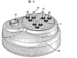
図9に本発明の一実施例に係る密閉形電動圧縮機の蓋体1Bの斜視図を示す。
FIG. 9 shows a perspective view of the
基本的には実施例1にて説明した通りである。本実施例の密閉形電動圧縮機は、9本の導電ピン5Aを1つのハーメボディ5Dに纏めた形でハーメチックターミナル5を構成している。図8等のハーメチックターミナル5は、3端子のクラスタ3Dを3つ使用して接続することを想定した構成としているが、導電ピン5Aの配置を変更し、専用の9端子のクラスタ3Dを使用することで、接続が1回で済むようにできるため、作業性を改善することができる。また、ハーメチックターミナル5の蓋体1Bへの溶接作業も1回で済むため、工程変更も簡略化できる。
Basically, it is as described in the first embodiment. In the hermetic electric compressor of the present embodiment, the
図10(a)に本発明の一実施例に係る密閉形電動圧縮機の蓋体1Bの斜視図、図10(b)に図10(a)の蓋体1Bに設置されているハーメチックターミナル5の拡大図を示す。
FIG. 10 (a) is a perspective view of a
基本的には実施例1にて説明した通りである。本実施例の密閉形電動圧縮機は、従来の密閉形電動圧縮機と同様に、蓋体1Bにハーメチックターミナル5を1つだけ設置することを目的に、ハーメチックターミナル5の導電ピン5Aを一本で3端子とし、1本の導電ピンに3つの接点を有する構成としている。
Basically, it is as described in the first embodiment. The hermetic electric compressor of this embodiment has one
一つの端子は、導電ピン5Aを中心に絶縁物5Cを介して、絶縁距離を確保しつつ、導電性を有する筒状の導電部材5Bを重ねる構成としている。このハーメチックターミナル5専用の接続端子を使用することにより、結線作業は従来と同一の1回の端子挿し込み作業となり、実施例1から5に対して、挿し込み作業数が減り、組み立ての作業性が改善され、更に、工程の設備改造についても軽減が可能となる。
One terminal has a configuration in which a cylindrical
図11に本発明の一実施例に係る密閉形電動圧縮機の縦断面図を示す。 FIG. 11 shows a longitudinal sectional view of a hermetic electric compressor according to one embodiment of the present invention.
基本的には実施例1にて説明した通りである。本実施例の密閉形電動圧縮機は、ハーメチックターミナル5を、密閉容器1を構成する筒体1Aの周面に設けた構成としている。これにより、固定子3の口出し線3Aをフレーム9、固定スクロール7の口出し線3A誘導溝を通して圧縮機構部2の上部まで引き上げる必要が無く、結線作業性が改善できると共に、口出し線3Aを短くできるので、原価低減を図ることが可能となる。図には明記していないが、ハーメチックターミナル5の仕様は、実施例1から7の仕様の何れでも構成可能である。
Basically, it is as described in the first embodiment. In the hermetic electric compressor of this embodiment, the
1…密閉容器
1A…筒体
1B…蓋体
1C…底体
1D…吸込パイプ
1E…吐出パイプ
1x…中性点
2…圧縮機構部
3…固定子
3A…口出し線
3B…固定子鉄心
3C…固定子巻線
3D…クラスタ
4…回転子
4A…バランスウエイト
4B…ピン
4C…回転子鉄心
5…ハーメチックターミナル
5A…導電ピン
5B…導電部材
5C…絶縁物
5D…ハーメボディ
6…クランク軸
7…固定スクロール
7A…吸込口
7B…吐出口
8…旋回スクロール
9…フレーム
10…オルダムリング
11…副軸受支持部材
12…副軸受
20…インバータ
30…巻線切替装置
30x…中性点
50…制御装置
100…第一熱交換器
150…減圧装置
200…第二熱交換器
DESCRIPTION OF SYMBOLS 1 ...
Claims (16)
前記モータに給電を行う導電ピンを9本有することを特徴とする密閉形電動圧縮機。 A hermetic electric compressor having a compression mechanism part, a DC brushless motor for driving the compression mechanism part, and a crankshaft for transmitting the rotational force of the motor to the compression mechanism part in the hermetic container In
A hermetic electric compressor having nine conductive pins for supplying power to the motor.
前記密閉容器に、3本の導電ピンを有するハーメチックターミナルを3つ設置したことを特徴とする密閉形電動圧縮機。 In claim 1,
A hermetic electric compressor, wherein three hermetic terminals having three conductive pins are installed in the hermetic container.
前記密閉容器に、5本の導電ピンを有するハーメチックターミナルと、4本の導電ピンを有するハーメチックターミナルをそれぞれ1つずつ設置したことを特徴とする密閉形電動圧縮機。 In claim 1,
A hermetic electric compressor, wherein one hermetic terminal having five conductive pins and one hermetic terminal having four conductive pins are installed in the sealed container.
3本の導電ピンを有する3つのハーメチックターミナルの内、少なくとも1つのハーメチックターミナルの導電ピンの径が、他の2つのハーメチックターミナルの導電ピンの径と異なることを特徴とする密閉形電動圧縮機。 In claim 2,
A hermetic electric compressor characterized in that, among three hermetic terminals having three conductive pins, the diameter of the conductive pins of at least one hermetic terminal is different from the diameters of the conductive pins of the other two hermetic terminals.
前記密閉容器に、9本の導電ピンを有するハーメチックターミナルを設置したことを特徴とする密閉形電動圧縮機。 In claim 1,
A hermetic electric compressor, wherein a hermetic terminal having nine conductive pins is installed in the hermetic container.
前記密閉容器に、1本の端子に3つの接点を有する導電ピンを3本設けたハーメチックターミナルを設置したことを特徴とする密閉形電動圧縮機。 In claim 1,
A hermetic terminal having a hermetic terminal provided with three conductive pins having three contacts on one terminal is installed in the hermetic container.
ハーメチックターミナルを、密閉容器の上面に設置したことを特徴とする密閉形電動圧縮機。 In any one of Claims 1 thru | or 6,
A hermetic type electric compressor characterized in that a hermetic terminal is installed on the upper surface of a hermetic container.
ハーメチックターミナルを、密閉容器の周面に設置したことを特徴とする密閉形電動圧縮機。 In any one of Claims 1 thru | or 6,
A hermetic type electric compressor characterized in that a hermetic terminal is installed on the peripheral surface of a hermetic container.
前記モータに給電を行う9本の導電ピンと、
前記密閉容器内に配設され、前記モータの巻線を構成する6つの巻線と、を備え、
前記6つの巻線のうちの3つの巻線の各一端を、前記9本の導電ピンのうち3つの導電ピンと接続し、前記密閉容器内で当該3つの巻線の他端を1つに接続して中性点を構成し、
残りの6つの導電ピンのうち2つずつを残りの3つの各巻線で接続した
ことを特徴とする密閉形電動圧縮機。 A hermetic electric compressor having a compression mechanism part, a DC brushless motor for driving the compression mechanism part, and a crankshaft for transmitting the rotational force of the motor to the compression mechanism part in the hermetic container In
9 conductive pins for supplying power to the motor;
6 windings disposed in the sealed container and constituting windings of the motor,
One end of each of the three windings of the six windings is connected to three of the nine conductive pins, and the other end of the three windings is connected to one in the sealed container. And configure a neutral point,
A hermetic electric compressor characterized in that two of the remaining six conductive pins are connected by the remaining three windings.
前記密閉形電動圧縮機の回転数を制御するインバータと、
前記インバータと前記密閉形電動圧縮機との間に配設され、その内部に中性点を構成することができる巻線切替装置と、
前記巻線切替装置内に中性点を構成するかしないかを制御する制御装置と、
を備え、
前記制御装置は、
前記巻線切替装置の内部に前記中性点を構成させ前記モータの固定子巻線を直列接続とし、または、
前記巻線切替装置の内部に前記中性点を構成させず前記モータの固定子巻線を並列接続として、
前記固定子巻線の直列接続と並列接続とを切り替える
ことを特徴とする冷凍サイクル装置。 A refrigeration cycle apparatus comprising the hermetic electric compressor according to claim 9, a first heat exchanger, a decompression device, and a second heat exchanger,
An inverter that controls the rotational speed of the hermetic electric compressor;
A winding switching device that is disposed between the inverter and the hermetic electric compressor, and can constitute a neutral point therein;
A control device for controlling whether or not to configure a neutral point in the winding switching device;
With
The controller is
The neutral point is configured inside the winding switching device and the stator winding of the motor is connected in series, or
Without configuring the neutral point inside the winding switching device, the stator winding of the motor as a parallel connection,
A refrigeration cycle apparatus that switches between series connection and parallel connection of the stator windings.
前記モータが低速回転の場合に直列接続とし、
前記モータが高速回転の場合に並列接続とする
ことを特徴とする冷凍サイクル装置。 In claim 10,
When the motor is rotating at low speed, it is connected in series,
A refrigeration cycle apparatus that is connected in parallel when the motor rotates at high speed.
前記モータが所定の回転数の場合に直列接続とし、
前記モータが前記所定の回転数よりも大きい場合に並列接続とする
ことを特徴とする冷凍サイクル装置。 In claim 10,
When the motor has a predetermined rotation speed, it is connected in series,
A refrigeration cycle apparatus, wherein the motor is connected in parallel when the motor is larger than the predetermined rotation speed.
前記モータが4,000rpm以下の場合には直列接続状態を保ち、
前記モータが3,000rpm以上の場合には並列接続状態を保つこととして、
ルームエアコンとして構成したことを特徴とする冷凍サイクル装置。 In claim 10,
When the motor is 4,000 rpm or less, keep the serial connection state,
When the motor is 3,000 rpm or more, keeping the parallel connection state,
A refrigeration cycle apparatus configured as a room air conditioner.
前記制御装置は、前記モータの出力−回転数に基づく効率のマップデータを保持しており、前記マップデータに基づいて、前記固定子巻線の直列接続と並列接続とを切り替えることを特徴とする冷凍サイクル装置。 In claim 10,
The control device holds efficiency map data based on the output-rotation speed of the motor, and switches between serial connection and parallel connection of the stator windings based on the map data. Refrigeration cycle equipment.
前記制御装置は、
中間条件では直列接続とし、
定格条件では並列接続とし、
ルームエアコンとして構成したことを特徴とする冷凍サイクル装置。 In claim 10,
The controller is
In intermediate conditions, use a series connection.
Parallel connection is used under the rated conditions.
A refrigeration cycle apparatus configured as a room air conditioner.
ハーメチックターミナルの導電ピンを、全てクランク軸設置方向に平行に設置したことを特徴とする密閉形電動圧縮機。 In claim 7,
Hermetic terminal conductive pins are all installed parallel to the crankshaft installation direction.
Priority Applications (3)
| Application Number | Priority Date | Filing Date | Title |
|---|---|---|---|
| JP2010094592A JP2011229221A (en) | 2010-04-16 | 2010-04-16 | Hermetic type electric compressor and refrigeration cycle device |
| KR20100077238A KR101179349B1 (en) | 2010-04-16 | 2010-08-11 | Closed type electric compressor, refrigeration cycle device |
| CN2010102582136A CN102220954A (en) | 2010-04-16 | 2010-08-18 | Sealed type electric compressor, refrigeration cycle device |
Applications Claiming Priority (1)
| Application Number | Priority Date | Filing Date | Title |
|---|---|---|---|
| JP2010094592A JP2011229221A (en) | 2010-04-16 | 2010-04-16 | Hermetic type electric compressor and refrigeration cycle device |
Publications (2)
| Publication Number | Publication Date |
|---|---|
| JP2011229221A true JP2011229221A (en) | 2011-11-10 |
| JP2011229221A5 JP2011229221A5 (en) | 2012-08-16 |
Family
ID=44777607
Family Applications (1)
| Application Number | Title | Priority Date | Filing Date |
|---|---|---|---|
| JP2010094592A Pending JP2011229221A (en) | 2010-04-16 | 2010-04-16 | Hermetic type electric compressor and refrigeration cycle device |
Country Status (3)
| Country | Link |
|---|---|
| JP (1) | JP2011229221A (en) |
| KR (1) | KR101179349B1 (en) |
| CN (1) | CN102220954A (en) |
Cited By (5)
| Publication number | Priority date | Publication date | Assignee | Title |
|---|---|---|---|---|
| JP2013192374A (en) * | 2012-03-14 | 2013-09-26 | Yaskawa Electric Corp | Motor drive device and vehicle |
| WO2019030813A1 (en) * | 2017-08-08 | 2019-02-14 | 三菱電機株式会社 | Outdoor unit of air conditioner |
| WO2019031081A1 (en) * | 2017-08-07 | 2019-02-14 | 三菱電機株式会社 | Air conditioner |
| EP3467308A1 (en) | 2017-10-05 | 2019-04-10 | Mitsubishi Heavy Industries Thermal Systems, Ltd. | Hermetic type compressor |
| WO2022003866A1 (en) * | 2020-07-01 | 2022-01-06 | コアレスモータ株式会社 | Rotating electrical machine and electric vehicle |
Families Citing this family (5)
| Publication number | Priority date | Publication date | Assignee | Title |
|---|---|---|---|---|
| JP5950873B2 (en) * | 2013-06-26 | 2016-07-13 | 三菱電機株式会社 | Three-phase motor, hermetic compressor, and refrigeration cycle apparatus |
| CN103439061B (en) * | 2013-07-30 | 2016-08-10 | 张家港市格致电器制造有限公司 | A kind of seal wiring seat air tightness detection apparatus |
| CN104348292B (en) * | 2013-07-31 | 2017-04-12 | 珠海格力电器股份有限公司 | Wiring mechanism, permanent magnet speed regulation motor and centrifugal refrigeration compressor |
| EP3489513B1 (en) * | 2016-07-29 | 2021-10-20 | Daikin Industries, Ltd. | Compressor assembly, compressor, and compressor production method |
| CZ309325B6 (en) * | 2017-08-09 | 2022-08-24 | Mitsubishi Electric Corporation | Compressor and refrigeration cycle equipment |
Citations (5)
| Publication number | Priority date | Publication date | Assignee | Title |
|---|---|---|---|---|
| JPS63307610A (en) * | 1987-06-08 | 1988-12-15 | Horikawa Densen Kk | Electrical wire |
| JPH06113517A (en) * | 1992-09-30 | 1994-04-22 | Daikin Ind Ltd | Dc brushless motor |
| JP2000274365A (en) * | 1999-01-21 | 2000-10-03 | Matsushita Electric Ind Co Ltd | Electric compressor |
| JP2003161261A (en) * | 2001-11-27 | 2003-06-06 | Sanyo Electric Co Ltd | Compressor |
| JP2007198224A (en) * | 2006-01-25 | 2007-08-09 | Daikin Ind Ltd | Cluster block and compressor |
Family Cites Families (6)
| Publication number | Priority date | Publication date | Assignee | Title |
|---|---|---|---|---|
| JPH06205573A (en) * | 1992-12-28 | 1994-07-22 | Honda Motor Co Ltd | Winding changeover type rotating electric machine |
| CN1222665A (en) * | 1998-01-08 | 1999-07-14 | 青岛海信集团公司 | Green frequency-variable air conditioner |
| JP4043637B2 (en) | 1999-03-29 | 2008-02-06 | 日本電産株式会社 | Brushless motor |
| CN1167879C (en) * | 2000-09-07 | 2004-09-22 | 科西亚数码电气(深圳)有限公司 | High-efficient energy-saving compressor for refrigerator |
| JP2003184775A (en) * | 2001-09-10 | 2003-07-03 | Hitachi Ltd | Scroll compressor and refrigeration unit for ammonia series refrigerant |
| JP2009071934A (en) | 2007-09-11 | 2009-04-02 | Toshiba Carrier Corp | Polarization method for electric compressor rotor, electric compressor, and refrigerating cycle device |
-
2010
- 2010-04-16 JP JP2010094592A patent/JP2011229221A/en active Pending
- 2010-08-11 KR KR20100077238A patent/KR101179349B1/en active IP Right Grant
- 2010-08-18 CN CN2010102582136A patent/CN102220954A/en active Pending
Patent Citations (5)
| Publication number | Priority date | Publication date | Assignee | Title |
|---|---|---|---|---|
| JPS63307610A (en) * | 1987-06-08 | 1988-12-15 | Horikawa Densen Kk | Electrical wire |
| JPH06113517A (en) * | 1992-09-30 | 1994-04-22 | Daikin Ind Ltd | Dc brushless motor |
| JP2000274365A (en) * | 1999-01-21 | 2000-10-03 | Matsushita Electric Ind Co Ltd | Electric compressor |
| JP2003161261A (en) * | 2001-11-27 | 2003-06-06 | Sanyo Electric Co Ltd | Compressor |
| JP2007198224A (en) * | 2006-01-25 | 2007-08-09 | Daikin Ind Ltd | Cluster block and compressor |
Cited By (8)
| Publication number | Priority date | Publication date | Assignee | Title |
|---|---|---|---|---|
| JP2013192374A (en) * | 2012-03-14 | 2013-09-26 | Yaskawa Electric Corp | Motor drive device and vehicle |
| WO2019031081A1 (en) * | 2017-08-07 | 2019-02-14 | 三菱電機株式会社 | Air conditioner |
| JPWO2019031081A1 (en) * | 2017-08-07 | 2020-02-27 | 三菱電機株式会社 | Air conditioner |
| WO2019030813A1 (en) * | 2017-08-08 | 2019-02-14 | 三菱電機株式会社 | Outdoor unit of air conditioner |
| WO2019030948A1 (en) | 2017-08-08 | 2019-02-14 | 三菱電機株式会社 | Outdoor unit of air conditioner |
| JPWO2019030948A1 (en) * | 2017-08-08 | 2019-12-12 | 三菱電機株式会社 | Air conditioner outdoor unit |
| EP3467308A1 (en) | 2017-10-05 | 2019-04-10 | Mitsubishi Heavy Industries Thermal Systems, Ltd. | Hermetic type compressor |
| WO2022003866A1 (en) * | 2020-07-01 | 2022-01-06 | コアレスモータ株式会社 | Rotating electrical machine and electric vehicle |
Also Published As
| Publication number | Publication date |
|---|---|
| KR101179349B1 (en) | 2012-09-03 |
| KR20110115943A (en) | 2011-10-24 |
| CN102220954A (en) | 2011-10-19 |
Similar Documents
| Publication | Publication Date | Title |
|---|---|---|
| KR101179349B1 (en) | Closed type electric compressor, refrigeration cycle device | |
| CN100593895C (en) | Automatic start type synchronous motor and compressor using said motor | |
| US6925824B2 (en) | Apparatus for driving a compressor and a refrigerating air conditioner | |
| CN102418700B (en) | Compressor and sealed rotating motor | |
| US20090214363A1 (en) | Motor and compressor including the same | |
| JP2016085005A (en) | Refrigeration cycle device | |
| JP2016086587A (en) | Motor | |
| CN108087234A (en) | Compressor and refrigeration equipment | |
| US20150010412A1 (en) | Stator, motor and compressor | |
| JP2020522226A (en) | Electric motor and compressor | |
| CN101769253A (en) | Integrated switched reluctance electric scroll compressor assembly for vehicle air conditioning | |
| JP5380487B2 (en) | Hermetic electric compressor | |
| CN108092436A (en) | Compressor and refrigeration equipment | |
| CN207761898U (en) | Compressor and refrigeration equipment | |
| CN207638434U (en) | Compressor and refrigeration equipment | |
| CN101488692B (en) | Three-winding single phase induction motor | |
| JP4595372B2 (en) | Compressor, compressor drive control device, and compressor drive control method | |
| JP7292441B2 (en) | Stator, electric motor, compressor, air conditioner, and stator manufacturing method | |
| CN100356065C (en) | Refrigeration compressor | |
| JP3079664B2 (en) | Hermetic compressor | |
| CN201588780U (en) | Integral switched reluctance electric scroll compressor assembly for vehicle air conditioning | |
| JP5645605B2 (en) | Electric compressor and control device thereof | |
| CN207761897U (en) | Compressor and refrigeration equipment | |
| CN2730013Y (en) | Saturable signal-phase asynchronous motor | |
| JP5045404B2 (en) | Hermetic compressor |
Legal Events
| Date | Code | Title | Description |
|---|---|---|---|
| A521 | Written amendment |
Free format text: JAPANESE INTERMEDIATE CODE: A523 Effective date: 20120622 |
|
| A621 | Written request for application examination |
Free format text: JAPANESE INTERMEDIATE CODE: A621 Effective date: 20120622 |
|
| A521 | Written amendment |
Free format text: JAPANESE INTERMEDIATE CODE: A523 Effective date: 20120622 |
|
| A977 | Report on retrieval |
Free format text: JAPANESE INTERMEDIATE CODE: A971007 Effective date: 20130904 |
|
| A131 | Notification of reasons for refusal |
Free format text: JAPANESE INTERMEDIATE CODE: A131 Effective date: 20130910 |
|
| A02 | Decision of refusal |
Free format text: JAPANESE INTERMEDIATE CODE: A02 Effective date: 20140401 |