JP2011217992A - Rehabilitation apparatus - Google Patents
Rehabilitation apparatus Download PDFInfo
- Publication number
- JP2011217992A JP2011217992A JP2010091194A JP2010091194A JP2011217992A JP 2011217992 A JP2011217992 A JP 2011217992A JP 2010091194 A JP2010091194 A JP 2010091194A JP 2010091194 A JP2010091194 A JP 2010091194A JP 2011217992 A JP2011217992 A JP 2011217992A
- Authority
- JP
- Japan
- Prior art keywords
- shaft
- foot
- rehabilitation device
- rotating shaft
- leg
- Prior art date
- Legal status (The legal status is an assumption and is not a legal conclusion. Google has not performed a legal analysis and makes no representation as to the accuracy of the status listed.)
- Withdrawn
Links
Images


Abstract
Description
本発明はリハビリ機器に関するものである。
特に本発明は、脳梗塞、脳血栓、くも膜下出血等の脳血管障害で倒れた後に、片麻痺の後遺症が残った片麻痺症状者が、効果的なリハビリテーション(機能回復訓練)を行うことができるように、種々の工夫をしたものである。
The present invention relates to a rehabilitation device.
In particular, the present invention enables an effective rehabilitation (function recovery training) to be performed on a hemiplegic symptom person who has left the hemiplegia after having fallen due to cerebrovascular disorders such as cerebral infarction, cerebral thrombus, and subarachnoid hemorrhage. As described above, various ideas have been made.
脳血管障害が発症した場合には、病院に入院して、医師により外科的治療(手術)や薬物を用いた内科的治療が行われる。
このような外科的治療・内科的治療が行われて、例えば筋肉、靱帯等の軟組織を痛めた急性症状の状態から脱却したとしても、身体運動に携わっている脳内の機能組織が損傷してしまうことが多くみられる。このような脳内機能組織の損傷が発生すると、身体の左右のうちどちらか一方(片側)に麻痺が起こり、身体の半分を動かすことができなくなる状態、即ち、片麻痺(半身付随)となる。
この場合、脳内に発生した損傷の位置や程度等に応じて、片麻痺の出る部分や、片麻痺の程度などが変わり、片麻痺の程度や障害の種類は個人差が大きい。
When a cerebrovascular disorder develops, the patient is admitted to a hospital and undergoes surgical treatment (surgery) or medical treatment using drugs.
Even if such a surgical treatment or medical treatment is performed and the soft tissue such as muscles and ligaments are removed from the state of acute symptoms that hurt, the functional tissue in the brain engaged in physical exercise is damaged. It is often seen. When such damage to the functional tissue in the brain occurs, paralysis occurs on either the left or right side (one side) of the body, and it becomes impossible to move half of the body, that is, hemiplegia (half body attachment). .
In this case, the part where hemiplegia occurs, the degree of hemiplegia, and the like vary depending on the position and degree of damage occurring in the brain, and the degree of hemiplegia and the type of disability vary greatly among individuals.
脳血管障害の後遺症として片麻痺が発生した場合には、片麻痺を軽減し更には身体機能を回復して家庭や職場に社会復帰するために、リハビリテーションが行われる。
脳血管障害の場合、急性期(発症から約1カ月以内)と回復期(発症後の約1カ月〜1年間)において、各時期に応じた最適な種類のリハビリテーションを如何に効果的に行うかが、機能回復において重要であると言われている。
When hemiplegia occurs as a sequelae of cerebrovascular disorders, rehabilitation is performed to relieve hemiplegia and restore physical function to return to the home or work.
In the case of cerebrovascular disorder, how effective rehabilitation of the optimum type is performed according to each period in the acute phase (within about 1 month from the onset) and recovery phase (about 1 month to 1 year after the onset). Is said to be important in functional recovery.
従前では、片麻痺になると、破壊された脳神経細胞は再生しないから、片麻痺は治療しても回復しないと考えられていた。このため、片麻痺症状者のリハビリテーションは、麻痺の無い側の下肢や上肢を鍛えて、歩行や日常生活ができるようにすることが目標とされてきた。
しかし、近年の脳科学の進歩によって、脳の一部が損傷されても、損傷を免れた他の部位が損傷された部位の役割を代行する能力、即ち、可塑性があることが明らかになり、麻痺を克服することを目的としたリハビリテーション治療も行われてきている。
In the past, it was thought that hemiplegia would not recover after treatment because hemiplegia would not regenerate destroyed brain neurons. For this reason, rehabilitation of persons with hemiplegic symptoms has been aimed at training the lower limbs and upper limbs on the side without paralysis so that they can walk and live daily.
However, recent advances in brain science have revealed that even if part of the brain is damaged, other parts that have escaped damage have the ability to substitute for the role of the damaged part, that is, plasticity, Rehabilitation treatment aimed at overcoming paralysis has also been performed.
このため、リハビリテーションにおいては、麻痺の無い側を鍛えて歩行や日常生活ができるようにするのみならず、麻痺の有る側を他人の介助等を受けながら動かして、麻痺側の腕や脚から脳に対して刺激を送ることにより神経系の可塑化(脳神経の代行能力の獲得、神経の再生化、再組織化)を促す必要がある。
神経系の可塑化を行う際には、麻痺側の腕や脚を介助者等により動かすのに併せて、麻痺症状者は麻痺側の腕や足を動かすようにイメージして、脳側から身体側に運動情報指令が伝わるようにイメージすることが効果的であると言われている。
つまり、麻痺側の腕や脚を強制的に動かして麻痺側の身体から脳に対して刺激(運動情報指令)を送るのに同期して、脳側から麻痺側の身体に向かって身体を動かすように指令する運動情報指令を送るようにイメージするという、双方向からの運動情報指令の連動により、可塑化を促進して機能回復を効果的に行うことができると言われている。
For this reason, in rehabilitation, not only can the side without paralysis be trained to enable walking and daily life, but also the side with paralysis can be moved while receiving assistance from others, and the brain can be moved from the paralyzed arm or leg to the brain. It is necessary to promote plasticization of the nervous system (acquisition of cranial nerve substitute ability, nerve regeneration, reorganization) by sending a stimulus to the brain.
When plasticizing the nervous system, in addition to moving the paralyzed arm and leg by a caregiver, etc., the paralyzed person imagines moving the paralyzed arm and leg and moves the body from the brain side. It is said that it is effective to image the movement information command to the side.
In other words, moving the body from the paralyzed side toward the paralyzed side in synchronization with sending a stimulus (motor information command) from the paralyzed side to the brain by forcibly moving the paralyzed arm or leg It is said that the function recovery can be effectively performed by promoting plasticization by interlocking the motion information commands from both directions, which is to imagine that the motion information commands to be commanded are sent.
このため例えば筋肉、靱帯等の軟組織を痛めている急性症状の状態から脱した後は、積極的にリハビリテーションが行われている。
急性期(発症から約1カ月以内)でのリハビリテーションは「理学療法」が中心となり、回復期(発症後の約1カ月〜1年間)でのリハビリテーションは、更に「作業療法」が追加される。
For this reason, for example, after relieving from the state of acute symptoms that are damaging soft tissues such as muscles and ligaments, rehabilitation is actively performed.
Rehabilitation in the acute phase (within about 1 month from the onset) is centered on “physical therapy”, and rehabilitation in the recovery phase (about 1 month to 1 year after the onset) further adds “occupational therapy”.
理学療法とは、身体機能に障害が生じた際に、その基本的な動作能力の改善を目的として運動療法や徒手的治療を行い、基本的身体能力の改善を図る療法である。この理学療法では、医師の指示にしたがい、理学療法士の補助によって、ゆっくりと寝返りをうったり、体を動かしたりしてみることから始まる。 Physical therapy is a therapy designed to improve basic physical ability by performing exercise therapy or manual treatment for the purpose of improving the basic movement ability when a physical function is impaired. This physical therapy begins by slowly turning over and moving the body with the assistance of a physical therapist, following the instructions of a doctor.
作業療法とは、いわば応用動作能力の改善を図る療法であり、ベッドに腰掛けたり、物を握ったりする訓練から開始する。これにより、手足関節が拘縮することを防止している。
更に、回復が進んでくると、更衣(着替え)・整容(姿・形を整える)といった身の廻り動作や、歩行訓練や、食事・トイレ・入浴・洗面などの日常生活動作の獲得・改善を目的とした動作訓練を行う。このような作業療法は、当初はベッドサイドで開始し、その後は実際の場面での動作訓練を行う。
Occupational therapy is a so-called therapy that improves applied motion skills, and starts with training to sit on a bed or hold an object. This prevents the limb joint from contracting.
Furthermore, as recovery progresses, we can acquire and improve everyday activities such as changing clothes (changing clothes) and dressing (dressing and shaping), walking training, and eating, toilets, bathing, and washing. Conduct the desired motion training. Such occupational therapy is initially started at the bedside, and then exercise training is performed in actual situations.
回復期のリハビリテーションが完了し、ある程度まで機能回復が得られたら、病院から退院をする。
退院後も、病院やリハビリ施設に定期的に通院してリハビリテーションを行うことが必要であり、医師や理学療法士が指示したメニューに沿った機能回復訓練を継続的に実行する。更に、片麻痺症状者自身も自発的・意欲的に身体を動かすように、との指導がされる。
このため自宅でのリハビリテーションの実行が重要であり、片麻痺の克服に向けての強い意欲と自主訓練の実行が必要である。
When the recovery phase of rehabilitation is complete and functional recovery is achieved to some extent, the patient is discharged from the hospital.
Even after discharge, it is necessary to go to a hospital or rehabilitation facility regularly to perform rehabilitation, and function recovery training is continuously performed according to the menus instructed by doctors and physical therapists. In addition, hemiplegic patients themselves are instructed to move their bodies voluntarily and eagerly.
For this reason, it is important to perform rehabilitation at home, and strong motivation and self-training are required to overcome hemiplegia.
病院やリハビリ施設においては、各種のリハビリ機器を備えこのリハビリ機器を用いたリハビリテーションが行われており、また自宅用のリハビリ機器も開発されている。
リハビリ機器としては、例えば、一対の直線状の並行棒を支柱により手すり状に水平に支持した歩行訓練用並行棒や、滑車に紐を掛けて紐の両端を左右の手で握り左右交互に紐を下方に引っ張る上肢上下運動訓練器や、自転車のペダル状の物を左右の手で握り回転させる上肢回転運動訓練器や、昇降階段や、スライドレール上で往復移動するスライド板の上に足を乗せて足をスライド移動させる足スライド運動訓練器など、各種のものが開発されている。
In hospitals and rehabilitation facilities, various rehabilitation devices are provided and rehabilitation using these rehabilitation devices is performed, and home rehabilitation devices are also being developed.
Examples of rehabilitation equipment include parallel walking bars that support a pair of straight parallel bars supported by handrails in a horizontal manner with a support, or a string on a pulley and grip both ends of the string with left and right hands. Legs on the upper and lower limbs exercise trainer that pulls down, the upper limb rotation exercise trainer that grips and rotates the pedal-like object of the bicycle with your left and right hands, the elevating stairs and the slide plate that moves back and forth on the slide rail Various devices have been developed, such as a foot slide exerciser that slides on the foot.
しかし、いずれのリハビリ機器も筋肉トレーニング的な機器が多く、更には症状に適したものが少ない上、使用が困難である。また、機器そのものが高価であり、一般家庭で容易にリハビリを継続することは困難であった。 However, many of the rehabilitation devices are muscle training devices, and few are suitable for symptoms, and are difficult to use. In addition, the equipment itself is expensive, and it has been difficult to continue rehabilitation easily in a general household.
上述したように、病院やリハビリ施設や自宅において、リハビリテーションが行われているが、実際に脳梗塞となり、後遺症として片麻痺となり、闘病やリハビリテーションを行ってきた体験者の話しによると、現状のリハビリテーションでは、種々の不具合があることが判明した。 As mentioned above, rehabilitation is being carried out at hospitals, rehabilitation facilities and homes, but according to the experiences of people who have actually suffered from cerebral infarction, hemiplegia as a sequelae, fighting illness and rehabilitation, the current rehabilitation Then, it was found that there are various problems.
例えば入院時においては、片麻痺症状者は、リハビリテーションを行う熱意や意志があるにもかかわらず、殆どの時間をベッドの上で静養しつつ待機しており、リハビリテーションを行う時間が短く、また、その頻度も少ないものである。
これは、身体の片側の手足が不自由な片麻痺症状者が一人でリハビリテーション訓練を行うと危険が伴うことから、片麻痺症状者が一人でリハビリテーション訓練をするのは無理があり、安全を確保すると共に効果的な訓練指導や介助を行うために、理学療法士や介助者が付き添って訓練をしなければならないからである。
また、リハビリ設備の広さやリハビリ機器の設置台数に制限があると共に、理学療法士や介助者の員数にも制限があるため、来院された多数の片麻痺症状者の全員が充分にリハビリテーションを行うことができないという事情もある。
For example, at the time of hospitalization, hemiplegic patients are waiting for most of the time resting on the bed, despite the enthusiasm and willingness to rehabilitate, and the time for rehabilitation is short, The frequency is low.
This is because it is dangerous for a person with hemiplegia who has difficulty in limbs on one side of the body to perform rehabilitation training alone, so it is impossible for a person with hemiplegia to perform rehabilitation training alone, ensuring safety. This is because a physical therapist and a caregiver must accompany the training in order to provide effective training guidance and assistance.
In addition, the size of rehabilitation facilities and the number of rehabilitation devices are limited, and the number of physiotherapists and caregivers is also limited, so that all of the patients with hemiplegia who visit the hospital will be fully rehabilitated. There are also circumstances where it is impossible.
一方、退院後においては、自宅でリハビリテーションを行う必要がある。このため各種の自宅用のリハビリ機器は存在するが、それらは、構造が複雑で大掛かりな上、回復対象機能が少なく高価なため、自宅で使用するには不便であり、しかも効果的な機能回復訓練をするには不足なものであった。 On the other hand, after discharge, it is necessary to perform rehabilitation at home. For this reason, there are various types of rehabilitation devices for home use, but they are complicated and large-scale, and have few functions to be recovered and are expensive, so they are inconvenient to use at home and have effective function recovery. It was not enough to train.
更に、片麻痺症状者となった者の実体験から言うと、現在のリハビリ機器は、片麻痺症状者の身体的・精神的状態や要望を充分には考慮したものとなっていない。
例えば、歩行訓練用並行棒では、平行棒の一方の端部から他方の端部まで平行棒を支えとして歩いてくると、片麻痺症状者は方向転換して今度は逆方向に向かって歩いていかなくてはならないが、方向転換をするのに、平行棒の持ち替えやつまづき等によるバランス崩し等で転倒の危険が伴うため、介助者などが付き添っている必要がある。このため、一台の歩行訓練用並行棒は、一人の片麻痺症状者のみしか使用することができず、また、片麻痺症状者が一人で自主的に訓練をすることができないものであった。
Furthermore, from the actual experience of the person who became a hemiplegic symptom, the current rehabilitation device does not fully consider the physical / mental state and demands of the person with hemiplegic symptom.
For example, in a parallel bar for walking training, if you walk from one end of the parallel bar to the other end with the parallel bar as a support, the person with hemiplegic symptoms will change direction and this time they will not be able to walk in the opposite direction. However, to change the direction, there is a risk of falling due to loss of balance caused by changing parallel bars or tripping. For this reason, one parallel bar for walking training can only be used by one hemiplegic symptom person, and one person with hemiplegia symptom cannot voluntarily train alone. .
また、ハンドルやペダルを回す上下肢回転運動訓練等では、ハンドルやペダルを把持しなければ、訓練に入ることができない。
しかし、例えば一方の腕が麻痺状態となっている場合、この麻痺側の手でハンドルやペダルを把持することはできず、したがって訓練中に外れるのを防止するため、何らかの方法(バンドで締める等)により、麻痺側の手をハンドルやペダルに固定しなければならない。
また、片麻痺症状者にとっては、麻痺側の腕の感覚が無いため、麻痺側の腕の位置を視覚によって確認することはできるが、麻痺側の腕の位置がどこにあるのかを身体感覚的に把握することができない。このため、麻痺側の腕を、ハンドルやペダルに近づけるという動作自体が、困難なものであった。
かかる事情が、一人で自主的に訓練することの阻害要因の一つになっていた。
Moreover, in the upper and lower limbs rotation exercise training in which the handle or the pedal is rotated, the training cannot be entered unless the handle or the pedal is grasped.
However, for example, when one arm is paralyzed, the hand on the paralyzed side cannot hold the handle or pedal, and therefore some method (such as tightening with a band) to prevent it from coming off during training. ) To fix the paralyzed hand to the handle or pedal.
For those with hemiplegia, there is no sense of the arm on the paralyzed side, so the position of the arm on the paralyzed side can be confirmed visually, but the position of the arm on the paralyzed side is physically sensed. I can't figure it out. For this reason, the operation itself of bringing the paralyzed arm closer to the handle or the pedal is difficult.
This situation was one of the obstacles to independent training by one person.
更に、上下肢回転運動訓練器等、種々のリハビリ機器では、片麻痺症状者の腕や足を、電動式機構により運動させるようになっているものもある。
電動式の機器では、確かに腕や脚が動かされて血行が良くなるというような一定の効果はある。しかし、それはあくまでも受動的な運動であり、片麻痺症状者が意図して自発的に行う運動ではなく、機能回復というより積極的な観点から見ると、リハビリテーションの効果が薄いものであった。
Further, in various rehabilitation devices such as an upper / lower limb rotation exercise trainer, there are some devices that move an arm and a leg of a hemiplegic symptom person by an electric mechanism.
In the electric device, there is a certain effect that the blood circulation is improved by moving the arms and legs. However, it is a passive exercise to the last, and it is not an exercise intentionally voluntarily performed by persons with hemiplegic symptoms, but the effect of rehabilitation is weak when viewed from a more positive viewpoint of functional recovery.
また、従来のリハビリ機器の回転運動では、身体をほぼ同一の軌跡に沿い回転移動運動をさせるようになっており、障害の度合や、リハビリテーションの回復度合に合わせて、身体の移動運動を微妙に変化させることはできない。このため、障害度合に合わせた適切な訓練ができないという不具合や、身体や脳さらには筋肉や神経に対する刺激が単調であるという不具合があった。
例えば、左右の腕を回転運動させる場合、従来の機器では、右腕と左腕の回転位相角度差は、180度に固定されており、回転位相角度差を片麻痺状態者の麻痺状態等に合わせて、変化調整することはできなかった。
これに対し、リハビリの初期の患者は、麻痺した腕が動き難いため、左右の腕が同じとなるクランク方向(クランク相互の位相差θ=0)が操作し易く、リハビリ中期では左右のクランク相互の位相に違いがあっても(0<θ<180°)回転することができ、リハビリ後期ではクランク相互の位相差が180°近辺でも(θ=180°)回転させ易くなるようである。即ち、現在の機器では最初からリハビリ後期の仕様となっており、症状により程度差があるが、好ましい方法とはいえない。
In addition, the conventional rotational movement of rehabilitation equipment allows the body to rotate and move along almost the same trajectory, and the body movement movement is subtly adjusted according to the degree of disability and the degree of recovery of rehabilitation. It cannot be changed. For this reason, there is a problem that proper training according to the degree of disability cannot be performed, and a problem that stimulation to the body, brain, muscles and nerves is monotonous.
For example, when rotating the left and right arms, in the conventional device, the rotation phase angle difference between the right arm and the left arm is fixed at 180 degrees, and the rotation phase angle difference is adjusted to the paralysis state of the person with hemiplegia. The change could not be adjusted.
On the other hand, in the early stage of rehabilitation, since the paralyzed arm is difficult to move, the crank direction (phase difference θ = 0 between the left and right arms) is easy to operate. It is possible to rotate even if there is a difference in phase (0 <θ <180 °), and in the latter stage of rehabilitation, it is easy to rotate even if the phase difference between the cranks is around 180 ° (θ = 180 °). In other words, current devices have specifications for the late stage of rehabilitation from the beginning, and there are differences depending on the symptoms, but this is not a preferable method.
更に、麻痺の無い側(健常側)の身体と、麻痺側の身体とを連動させて自発的に訓練するという発想は、従来のリハビリ機器には存在していなかった。つまり、健常側の身体の力や動作を、麻痺側の身体に伝達して、麻痺側の身体を自発的、積極的に回復させ、これにより神経系の可塑化(脳神経の代行能力の獲得、神経の再生化、再組織化)を積極的に促すリハビリ機器は存在していなかった。
また従来のリハビリ機器は単機能のものが殆どであったが、これでは訓練に厭き易い上、使用筋肉等が決まるので、広範な可塑化対応ができなかった。
Furthermore, the idea of voluntarily training the body on the side without paralysis (healthy side) and the body on the paralysis side did not exist in conventional rehabilitation equipment. In other words, the power and movements of the healthy body are transmitted to the paralyzed body, and the paralyzed body is voluntarily and actively recovered, thereby plasticizing the nervous system (acquiring the ability to substitute for cranial nerves, There was no rehabilitation device that actively promoted nerve regeneration and reorganization.
In addition, most of the conventional rehabilitation devices have a single function, but this makes it easy to go to training and determines the muscles to be used.
本発明は、上記従来のリハビリ機器の不具合を解消して、健常側の身体によりリハビリ機器を動作させ、動力伝達機構を介して上・下肢間の動力伝達をして、麻痺側の身体を健常側の力で動かすことにより効果的なリハビリテーションを行い、麻痺側の身体を積極的に機能回復させることができるリハビリ機器を提供することを目的とする。
即ち健常側の力でリハビリ機器を動かし、これに付随して麻痺側を動かすようにしたり、更にその運動後、同種の運動を行うようにしたりしたので、先の健常側の力、或いは先の運動により脳に刺激を与えた後、その刺激を回想しながら麻痺側を動かすことになり、脳の記憶の可塑化が一層促進される。
この理由から、リハビリに必要な機能をリハビリ機器に複合化させることにより、短時間で関連域或いは他機能に移行することができ、したがって脳の可塑化を一層効果的にできると共に、装置としてもコンパクトなリハビリ機器を提供することを目的とする。
The present invention eliminates the problems of the conventional rehabilitation device, operates the rehabilitation device with the healthy body, transmits power between the upper and lower limbs via the power transmission mechanism, and maintains the paralyzed body healthy. An object of the present invention is to provide a rehabilitation device capable of performing effective rehabilitation by moving with a side force and actively recovering the function of the paralyzed body.
That is, the rehabilitation device is moved with the force of the healthy side, and the paralyzed side is moved along with this, and the same kind of movement is performed after the exercise. After stimulating the brain by exercise, the paralyzed side is moved while recalling the stimulus, and the plasticization of the memory of the brain is further promoted.
For this reason, by combining functions necessary for rehabilitation with a rehabilitation device, it is possible to shift to related areas or other functions in a short time, and therefore, the plasticization of the brain can be made more effective, and also as a device The purpose is to provide a compact rehabilitation device.
上記課題を解決する本発明の腕回転運動用のリハビリ機器の構成は、
本体支持部に対して回転自在に支持されており、しかも、両端部が多角柱の形状になっている回転軸と、
基端部には、前記回転軸の端部に緊密に嵌合する多角形の嵌合孔が形成されており、当該嵌合孔に前記回転軸の一方の端部を嵌合することにより前記回転軸に組み付けられ、しかも、前記回転軸の一方の端部に対する前記嵌合孔の回転位相位置をずらすことにより、前記回転軸に対する回転位相位置を変化させることができる第1の手用のクランクと、
前記回転軸に対して略平行となる状態で、第1の手用のクランクの先端部に設けた第1の手用軸と、
前記第1の手用軸に回転自在に組み付けられた第1のハンドルと、
基端部には、前記回転軸の端部に緊密に嵌合する多角形の嵌合孔が形成されており、当該嵌合孔に前記回転軸の他方の端部を嵌合することにより前記回転軸に組み付けられ、しかも、前記回転軸の他方の端部に対する前記嵌合孔の回転位相位置をずらすことにより、前記回転軸に対する回転位相位置を変化させることができる第2の手用のクランクと、
前記回転軸に対して略平行となる状態で、第2の手用のクランクの先端部に設けた第2の手用軸と、
前記第2の手用軸に回転自在に組み付けられた第2のハンドルと、
を有することを特徴とする。
この場合、
前記嵌合孔の形状は、正多角形であり、
前記回転軸の両端部の形状は、前記嵌合孔に緊密に嵌合する複数の辺を有する多角柱形状になっていることを特徴とし、
前記第2のハンドルは、人間の手及び前腕を支持する支持板と、前記支持板を前記前腕に取り付けるバインダー部と、第2の手用軸が回転自在且つ緊密に嵌入する把持孔が形成された把持軸と、前記把持軸が取付けられるとともに前記把持軸が前記支持板に対して略平行となるように前記支持板に取り付けられる把持板とで成る前腕ホルダーであることを特徴とする。
The structure of the rehabilitation device for arm rotation motion of the present invention that solves the above problems is as follows.
A rotating shaft that is rotatably supported with respect to the main body support portion, and that has both ends in the shape of a polygonal column,
The base end is formed with a polygonal fitting hole that fits tightly into the end of the rotating shaft, and by fitting one end of the rotating shaft into the fitting hole, A first hand crank that is assembled to the rotating shaft and can change the rotating phase position with respect to the rotating shaft by shifting the rotating phase position of the fitting hole with respect to one end of the rotating shaft. When,
A first hand shaft provided at a tip portion of a first hand crank in a state of being substantially parallel to the rotation shaft;
A first handle rotatably assembled to the first hand shaft;
The base end portion is formed with a polygonal fitting hole that fits tightly into the end portion of the rotating shaft, and the other end portion of the rotating shaft is fitted into the fitting hole. A second hand crank that is assembled to the rotation shaft and can change the rotation phase position with respect to the rotation shaft by shifting the rotation phase position of the fitting hole with respect to the other end of the rotation shaft. When,
A second hand shaft provided at a tip portion of a second hand crank in a state of being substantially parallel to the rotation shaft;
A second handle rotatably assembled to the second hand shaft;
It is characterized by having.
in this case,
The shape of the fitting hole is a regular polygon,
The shape of both end portions of the rotating shaft is a polygonal column shape having a plurality of sides closely fitted in the fitting hole,
The second handle is formed with a support plate for supporting a human hand and a forearm, a binder portion for attaching the support plate to the forearm, and a gripping hole into which the second hand shaft is rotatably and closely fitted. A forearm holder comprising a gripping shaft and a gripping plate attached to the support plate so that the gripping shaft is attached and the gripping shaft is substantially parallel to the support plate.
また本発明の脚回転運動用のリハビリ機器は、
本体支持部に対して回転自在に支持されており、しかも、両端部が多角柱の形状になっている回転軸と、
基端部には、前記回転軸の端部に緊密に嵌合する多角形の嵌合孔が形成されており、当該嵌合孔に前記回転軸の一方の端部を嵌合することにより前記回転軸に組み付けられ、しかも、前記回転軸の一方の端部に対する前記嵌合孔の回転位相位置をずらすことにより、前記回転軸に対する回転位相位置を変化させることができる第1の足用のクランクと、
前記回転軸に対して略平行となる状態で、第1の足用のクランクの先端部に設けた第1の足用軸と、
前記第1の足用軸に回転自在に組み付けられた第1のペダルと、
基端部には、前記回転軸の端部に緊密に嵌合する多角形の嵌合孔が形成されており、当該嵌合孔に前記回転軸の他方の端部を嵌合することにより前記回転軸に組み付けられ、しかも、前記回転軸の他方の端部に対する前記嵌合孔の回転位相位置をずらすことにより、前記回転軸に対する回転位相位置を変化させることができる第2の足用のクランクと、
前記回転軸に対して略平行となる状態で、第2の足用のクランクの先端部に設けた第2の足用軸と、
第2の足用軸に回転自在に組み付けられた第2のペダルと、
を有することを特徴とする。
この場合、
前記嵌合孔の形状は、正多角形であり、
前記回転軸の両端部の形状は、前記嵌合孔に緊密に嵌合する複数の辺を有する多角柱形状になっていることを特徴とし、
前記第2のペダルは、人間の足を支える足固定部本体及び人間の足を前記足固定部本体に固定する足固定手段で構成された足固定部と、前記足固定部の底面に配置されると共に回動連接具により回動可能に前記足固定部に連接された基台と、前記基台の底面に配置されて前記第2の足用軸を回転自在に支持する嵌入支持部とでなる足ホルダーであることを特徴とし、
前記足固定手段は、足甲を囲む鼻緒であることを特徴とし、
前記足固定手段は、踵を囲む踵固定部であることを特徴とし、
前記嵌入支持部は、前記基台の裏面に設けられており前記第2の足用軸に嵌合する嵌合手段と、前記嵌合手段に嵌合された前記第2の足用軸を前記嵌合手段に対して係止及び係止解除可能な係止手段とから成ることを特徴とする。
Moreover, the rehabilitation equipment for leg rotation motion of the present invention is:
A rotating shaft that is rotatably supported with respect to the main body support portion, and that has both ends in the shape of a polygonal column,
The base end is formed with a polygonal fitting hole that fits tightly into the end of the rotating shaft, and by fitting one end of the rotating shaft into the fitting hole, A crank for a first foot that is assembled to a rotating shaft and can change the rotating phase position with respect to the rotating shaft by shifting the rotating phase position of the fitting hole with respect to one end of the rotating shaft. When,
A first foot shaft provided at a tip portion of a first foot crank in a state of being substantially parallel to the rotation shaft;
A first pedal rotatably assembled to the first foot shaft;
The base end portion is formed with a polygonal fitting hole that fits tightly into the end portion of the rotating shaft, and the other end portion of the rotating shaft is fitted into the fitting hole. A crank for a second foot that is assembled to the rotating shaft and can change the rotating phase position with respect to the rotating shaft by shifting the rotating phase position of the fitting hole with respect to the other end of the rotating shaft. When,
A second foot shaft provided at the tip of the second foot crank in a state of being substantially parallel to the rotation shaft;
A second pedal rotatably assembled to the second foot shaft;
It is characterized by having.
in this case,
The shape of the fitting hole is a regular polygon,
The shape of both end portions of the rotating shaft is a polygonal column shape having a plurality of sides closely fitted in the fitting hole,
The second pedal is disposed on a foot fixing portion composed of a foot fixing portion main body for supporting a human foot and a foot fixing means for fixing the human foot to the foot fixing portion main body, and a bottom surface of the foot fixing portion. And a base that is connected to the foot fixing portion so as to be rotatable by a rotation connecting tool, and an insertion support portion that is disposed on the bottom surface of the base and rotatably supports the second foot shaft. It is a foot holder that
The foot fixing means is a chord surrounding the instep,
The foot fixing means is a heel fixing portion surrounding the heel,
The fitting support portion is provided on the back surface of the base and has a fitting means for fitting to the second foot shaft, and the second foot shaft fitted to the fitting means. It comprises locking means that can be locked and unlocked with respect to the fitting means.
また本発明のリハビリ機器は、
前記の腕回転運動用のリハビリ機器と、
前記の脚回転運動用のリハビリ機器と、
前記腕回転運動用のリハビリ機器の回転軸と前記脚回転運動用のリハビリ機器の回転軸との間で回転力を伝達する回転力伝達機構と、
を有することを特徴とする。
この場合、
前記回転力伝達機構は、前記腕回転運動用のリハビリ機器の前記回転軸に設けられた腕用のプーリーと、前記脚回転運動用のリハビリ機器の前記回転軸に設けられた脚用のプーリーと、前記腕用のプーリーと前記脚用のプーリーとの間で回転力を伝達する回転力伝達手段とから成ることを特徴とし、
前記腕用のプーリー及び前記脚用のプーリーは共に歯付きプーリーであり、前記回転力伝達手段は歯付きベルトであることを特徴とし、
前記腕用のプーリー及び前記脚用のプーリーは共にチェーンスプロケットであり、前記回転力伝達手段はチェーンであることを特徴とする。
The rehabilitation device of the present invention is
A rehabilitation device for rotating the arm,
A rehabilitation device for rotating the leg,
A rotational force transmission mechanism for transmitting rotational force between the rotational axis of the rehabilitation device for arm rotational motion and the rotational axis of the rehabilitation device for leg rotational motion;
It is characterized by having.
in this case,
The rotational force transmission mechanism includes a pulley for an arm provided on the rotation shaft of the rehabilitation device for rotating the arm, and a pulley for a leg provided on the rotation shaft of the rehabilitation device for rotating the leg. , Comprising a rotational force transmitting means for transmitting rotational force between the arm pulley and the leg pulley,
The arm pulley and the leg pulley are both toothed pulleys, and the rotational force transmitting means is a toothed belt,
Both the arm pulley and the leg pulley are chain sprockets, and the rotational force transmitting means is a chain.
また本発明の複合リハビリ機器は、
複数本の支持棒と、この複数本の支持棒の頂部に連結されて水平に支持されたループ状の手すり棒とでなる連続歩行用のリハビリ機器と、
前記の腕回転運動用リハビリ機器と前記の脚回転運動用のリハビリ機器とを備え、
前記手すり棒の内側に、前記のリハビリ機器が配置されていることを特徴とする。
また本発明の複合リハビリ機器において、前記ループ状の手すり棒には、少なくとも1カ所の開閉手段を有することを特徴とする。
The composite rehabilitation device of the present invention is
A rehabilitation device for continuous walking composed of a plurality of support bars and a loop-shaped handrail bar connected to the top of the plurality of support bars and supported horizontally;
The arm rotation exercise rehabilitation device and the leg rotation exercise rehabilitation device,
The rehabilitation device is arranged inside the handrail bar.
In the composite rehabilitation device of the present invention, the loop-shaped handrail bar has at least one opening / closing means.
本発明の回転運動用のリハビリ機器によれば、健常側の身体(手や足)により発した力を、機械により伝達して、麻痺側の身体(手や足)を動かしてリハビリテーションをするため、片麻痺症状者の自発的なイメージにより、健常側と麻痺側の身体(脳内の関連領域を含む)がペアとなって連動運動するため、可塑性に対して効果的なリハビリテーションができる。
更に、前腕ホルダーや足ホルダーを使用することにより、麻痺側の身体(手や足)を、リハビリ機器のクランクに支持することができ、介助者等がいなくても片麻痺症状者だけで容易・安全且つ可塑性に対しても十分効果的にリハビリテーションを行うことができる。
According to the rehabilitation device for rotational movement of the present invention, the force generated by the healthy body (hand or foot) is transmitted by the machine, and the rehabilitation is performed by moving the paralyzed body (hand or foot). Because of the spontaneous image of the hemiplegic symptom, the healthy side and the paralyzed body (including related areas in the brain) work together as a pair, so that effective rehabilitation for plasticity can be achieved.
Furthermore, by using the forearm holder or foot holder, the paralyzed body (hands and feet) can be supported by the crank of the rehabilitation device, and it is easy for only those with hemiplegic symptoms without an assistant. Rehabilitation can be performed sufficiently effectively for safety and plasticity.
また本発明のリハビリ機器によれば、手すり棒をループ状に形成したため、平行棒に比べ身体の真反対の方向転換をすることなく連続的に歩行訓練をすることができる。 Further, according to the rehabilitation device of the present invention, since the handrail bar is formed in a loop shape, the walking training can be continuously performed without changing the direction opposite to the body as compared with the parallel bar.
また連続歩行用のリハビリ機器と回転運動用のリハビリ機器を合体させた複合機器としたので、複数のリハビリテーションが可能であると共に、全体として機器構成をコンパクトにすることができ、病院等のみならず、設置スペースが限られている自宅においても使用することができる。
更には、ループ状に形成した手すり棒の中に、回転運動用のリハビリ機器を設けるという複合化構成にしたため、極めて短時間で、回転運動と手すりを利用した歩行運動とを行えるので、可塑性に対しても両運動を結合することができる。
In addition, the rehabilitation device for continuous walking and the rehabilitation device for rotary motion are combined into a composite device, so multiple rehabilitations are possible and the overall device configuration can be made compact. It can also be used at home where installation space is limited.
Furthermore, since the rehabilitation equipment for rotational motion is provided in the handrail rod formed in a loop shape, it is possible to perform rotational motion and walking motion using handrails in a very short time, so that plasticity is improved. Both movements can be combined.
また本発明は、脳血管障害等により片麻痺となった片麻痺症状者が、リハビリテーションを行うのに利用できる他、パーキンソン病等の運動機能低下を呈する症状者が、運動機能を維持するために利用したり、高齢者など身体機能能力が衰えた人が、健康度を向上するために利用したりすることが可能である。 In addition, the present invention can be used for a hemiplegic symptom who has become hemiplegic due to a cerebrovascular disorder or the like to perform rehabilitation, and for a symptomatic person who exhibits decreased motor function such as Parkinson's disease to maintain motor function. It can be used by people who have diminished physical function, such as elderly people, to improve their health.
以下、本発明を実施するための形態について、身体の左側が麻痺した患者用とした実施例に基づき詳細に説明する。 Hereinafter, the form for implementing this invention is demonstrated in detail based on the Example used for the patient with which the left side of the body was paralyzed.
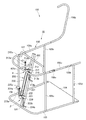
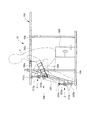
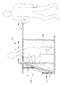
図1,図2は本発明の実施例に係る複合リハビリ機器10を示す。
この複合リハビリ機器10は、連続歩行用のリハビリ機器100と回転運動用のリハビリ機器200とを合体させた複合機器となっている。
1 and 2 show a
The
連続歩行用のリハビリ機器100では、前縁棒101と、右縁棒102と、左縁棒103が接合・連結されて、コ字状の底面構造体が形成されている。
このように、前縁棒101と、右縁棒102と、左縁棒103を連結してなるコ字状の底面構造体に、底板104が固定されている。
In the
In this way, the
支柱105aは、右縁棒102のうち中央位置よりもやや前寄り(前縁棒101側)の位置に接合されており、垂直上方に伸びている。支柱105bは、右縁棒102のうち後縁側の位置に接合されており、垂直上方に伸びている。
支柱105cは、左縁棒103のうち中央位置よりもやや前寄り(前縁棒101側)の位置に接合されており、垂直上方に伸びている。支柱105dは、左縁棒103のうち後縁側の位置に接合されており、垂直上方に伸びている。
The
The
ループ状の手すり棒106は、U字状の手すり棒材106aとU字状の手すり棒材106bを連結して構成したものである。
このうち、U字状の手すり棒材106aは、4本の支柱105a,105b,105c,105dの頂部に連結されて、水平に支持されている。
The loop-shaped
Among these, the
U字状の手すり棒材106bの一端(右端)は、手すり棒材106aの一端(右端)に回転自在に連結されており、手すり棒材106bの他端(左端)は手すり棒材106aの他端(左端)に対して着脱自在に連結されている。
このため、図1に示すように、手すり棒材106bの他端(左端)を手すり棒材106aの他端(左端)に連結したときには、連結された手すり棒材106a,106bによりループ状で水平な手すり棒106が形成される。
一方、図2に示すように、手すり棒材106bの他端(左端)を手すり棒材106aの他端(左端)から開放して、手すり棒材106bをその一端(右端)を中心に回転させると、ループ状の手すり棒106の一部が開放される。このように開放状態になると、ループ状の手すり棒106で囲まれた内部空間と、ループ状の手すり棒106の外周側である外部空間との間で、人間が出入りすることができる。
One end (right end) of the
Therefore, as shown in FIG. 1, when the other end (left end) of the
On the other hand, as shown in FIG. 2, the other end (left end) of the
なお、人間がループ状の手すり棒106内に出入りするには、図2に示すように、手すり棒材106bを回転開閉して行う他、手すり棒材106aの一部を除去することでも可能である。
即ち、図1に示すように、手すり棒材106aの右縁側または左縁側の一部(以下、左縁側で説明する)である手すり開閉部材106cを切り取り、この手すり開閉部材106cの左端にスライド部材108aを設け、右端に蝶番部材108bを設ける。
このような構成にすることにより、スライド部材108aを右にスライドさせると、手すり棒材106aと手すり開閉部材106cとの断端が露出するので、蝶番部材108bの所から手すり開閉部材106cを下方に折曲するとループ状の手すり棒106は開状態になる。
次に開状態から閉状態にするには、下方に垂れている手すり開閉部材106cを蝶番部材108bを回転中心として上方に回動させて水平状態とし、スライド部材108aを左にスライドさせて、手すり開閉部材106cと手すり部材106aとを連結する。
As shown in FIG. 2, a person can enter and exit the looped
That is, as shown in FIG. 1, a handrail opening / closing
With such a configuration, when the
Next, in order to change from the open state to the closed state, the handrail opening / closing
ループ状の手すり棒106に更に強度が必要な場合には、手すり棒材106aの右側端から左側端にわたり、連結棒107が配置されることが望ましい。
When the loop-shaped
回転運動用のリハビリ機器200は、連続歩行用のリハビリ機器100のループ状の手すり棒106の内側に位置するように配置されている。
The
回転運動用のリハビリ機器200の本体支柱(本体支持部)201は、その下端が前縁棒101の略中央部に連結・固定され、その上部が支持棒202を介して手すり棒材106aに連結・固定されている。
なお、支持棒202が1本で弱い場合には、図示はしないが2本の支持棒でV字状にし、V字状の合わさり部分を本体支柱201に連結・固定する等して、剛性アップを図ってもよい。
このようにして、本体支柱201は、前縁棒101及び手すり棒材106aに固定されて、全体で斜めになった状態で立設されている。
The main body column (main body support portion) 201 of the
If one
In this way, the
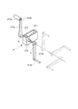
本体支柱201の上側部分には、回転軸ホルダー210が固定されている。この回転軸ホルダー210は、長方形の板金を折り曲げ加工して4角筒形に形成したものであり、回転軸211を回転自在に支持している。具体的には、ころがり軸受やすべり軸受等を用いて、回転軸211を回転軸ホルダー210に回転自在に支持している。
なお、回転軸ホルダー210は、前記機能を有するものであれば、形状や構成を限定するものではない。
A
The
回転軸211の中央位置、即ち、回転軸211のうち回転軸ホルダー210の内部空間に位置する部分には、プーリー212が固定されている。したがって、回転軸211とプーリー212は一体となって回転する。
A
回転軸211の右端には、手用のクランク213aの基端部が着脱自在に組み付けられており、クランク213aの先端部には、回転軸211に対して略平行な第1の手用軸214aが固着・設置されている。この第1の手用軸214aには、健常な手で把持し易い円筒状等のハンドル215aが回転自在かつ着脱自在に組み付けられている。
回転軸211の左端には、手用のクランク213bの基端部が着脱自在に組み付けられており、クランク213bの先端部には、回転軸211に対して略平行な第2の手用軸214bが固着・設置されている。この第2の手用軸214bには、健常な手で把持し易い円筒状等のハンドル215bや、麻痺した前腕を支持する手段である後述の前腕ホルダー300が、回転自在かつ着脱自在に組み付けられるようになっている。
A proximal end portion of a
A proximal end portion of a hand crank 213b is detachably attached to the left end of the
このようにして、回転軸ホルダー210、回転軸211、プーリー212、クランク213a,213b、手用軸214a,214b、ハンドル215a、215bにより、腕回転運動用のリハビリ機器αが構成されている。
なお、図1に示すように、クランク213a,213bの先端部に固着・設置した手用軸214a,214bに、それぞれ、ハンドル215a,215bを組み付けてもよいが、後述するように、片麻痺症状者の状態やリハビリテーションに応じて、図2に示すように、ハンドル215a,215bの一方のみを組み付けるようにすることもできる。
なお図2の形態は、左側の初期の片麻痺(未回復状態)における使用状態を示し、手用軸214bには後述する前腕ホルダー300が取り付けられるようになっている。
In this way, the
As shown in FIG. 1, handles 215a and 215b may be assembled to the
2 shows the use state in the initial left hemiplegia (unrecovered state), and a
本体支柱201の下側部分には、回転軸ホルダー220が固定されている。この回転軸ホルダー220は、長方形の板金を折り曲げ加工して4角筒形に形成したものであり、回転軸221を回転自在に支持している。具体的には、ころがり軸受やすべり軸受等を用いて、回転軸221を回転軸ホルダー220に回転自在に支持している。
なお、回転軸ホルダー220は、前記機能を有するものであれば、形状や構成を限定するものではない。
A
The
回転軸221の中央位置、即ち、回転軸221のうち回転軸ホルダー220の内部空間に位置する部分には、プーリー222が固定されている。したがって、回転軸221とプーリー222は一体となって回転する。
A
回転軸221の右端には、足用のクランク223aの基端部が着脱自在に組み付けられており、クランク223aの先端部には、回転軸221に対して略平行な第1の足用軸224aが固着・設置されている。この第1の足用軸224aには、ペダル225aが回転自在かつ着脱自在に組み付けられている。
回転軸221の左端には、足用のクランク223bの基端部が着脱自在に組み付けられており、クランク223bの先端部には、回転軸221に対して略平行な第2の足用軸224bが固着・設置されている。この第2の足用軸224bには、ペダル225bや、麻痺した前足を支持する手段である後述の足ホルダー400が、回転自在かつ着脱自在に組み付けられるようになっている。
A base end portion of a foot crank 223 a is detachably attached to the right end of the
A base end portion of a foot crank 223b is detachably attached to the left end of the
このようにして、回転軸ホルダー220、回転軸221、プーリー222、クランク223a,223b、足用軸224a,224b、ペダル225a、225bにより、脚回転運動用のリハビリ機器βが構成されている。
なお、クランク223a,223bの先端部に固着・設置した足用軸224a,224bに、それぞれ、ペダル225a,225bの両方を組み付けてもよいが、後述するように、片麻痺症状者の状態やリハビリテーションに応じて、ペダル225a,225bの一方のみを組み付けるようにすることもできる。
In this way, the
Both the
歯付きベルト230は、上側の腕回転運動用のリハビリ機器αのプーリー212と、下側の脚回転運動用のリハビリ機器βのプーリー222との間に掛け渡されている。即ち、両プーリー212,222は、歯付きベルト230とかみ合い可能な歯付きプーリーである。
このため、上側のプーリー212が回転駆動されると、この回転力が歯付きベルト230を介して下側のプーリー222に伝達し、逆に、下側のプーリー222が回転駆動されると、この回転力が歯付きベルト230を介して上側のプーリー212に伝達する。
以上は、歯付きベルト230と歯付きプーリー212,222で説明したが、チェーンとスプロケットでもよく、更には傘歯車を用いた回転軸伝達機構でもよい。
The
Therefore, when the
Although the above has been described with the
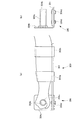
ここで、腕回転運動用のリハビリ機器αにおける、回転軸211とクランク213a,213bとの組み付け状態について、図3(a),図4を参照して説明する。
図3(a),図4に示すように、回転軸211の両端部分は、主形状が多角柱の形状(本例では4角柱の形状)になっている。一方、クランク213a,213bの基端部には、回転軸211の両端部分の形状(本例では4角柱の形状)に対応する主形状が多角形(本例では4角形)の嵌合孔hが形成されている。つまり、クランク213a,213bに形成した嵌合孔hが、回転軸211の両端部に、緊密に嵌合することができるようになっている。
Here, the assembled state of the
As shown in FIGS. 3A and 4, the main shapes of both end portions of the
このため、クランク213aの基端部の嵌合孔hを回転軸211の右端部分に嵌入し、ボルト等で固定することにより、クランク213aと回転軸211との組み付けができる。また、クランク213bの基端部の嵌合孔hを回転軸211の左端部分に嵌入し、ボルト等で固定することにより、クランク213bと回転軸211との組み付けができる。
この場合、回転軸211に対して、クランク213a,213bの回転位相位置は、90度づつずらした任意の位置とすることができる。
For this reason, the
In this case, the rotational phase positions of the
したがって、左右のクランク213a,213bの相対的な回転位相角度差を、図4に実線で示すように、180度にしたり、図4に点線で示すように、+90度、−90度、0度にしたりすることもできる。図4では、右側のクランク213aの回転位相位置を固定して左側のクランク213bの回転位相位置をずらしているが、左側のクランク213bの回転位相位置を固定して右側のクランク213aの回転位相位置をずらすようにしてもよい。
Therefore, the relative rotational phase angle difference between the left and
更に、回転軸211の両端部分の多角柱の形状及びクランク213a,213bの嵌合孔hの形状を、4角形よりも多い多角形とすることにより、左右のクランク213a,213bの相対的な回転位相角度差の種類を増加することもできる。
なお、回転位相角度差を構成させるには、多角形は正多角形が好ましいが、この場合、図3(b),(c)に示すように、嵌合孔hは正多角形であることが必要であるが、回転軸211の端部の形状は、嵌合孔hと緊密に嵌合する主形状が正多角形であれば、一部の切欠があってもよい。つまり、回転軸211の端部の形状は、正多角形である嵌合孔hに緊密に嵌合する複数の辺を有する多角柱形状であればどのような形状であっても構わない。
Further, by making the shape of the polygonal column at both ends of the
In order to configure the rotational phase angle difference, the polygon is preferably a regular polygon. In this case, as shown in FIGS. 3B and 3C, the fitting hole h is a regular polygon. However, the shape of the end portion of the
脚回転運動用のリハビリ機器βにおける、回転軸221とクランク223a,223bとの組み付け状態は、前述した、腕回転運動用のリハビリ機器αにおける、回転軸211とクランク213a,213bとの組み付け状態と同様になっている。
つまり、回転軸221の両端部分は、多角柱の形状(本例では4角柱の形状)になっており、クランク223a,223bの基端部には、回転軸221の両端部分の形状(本例では4角柱の形状)に対応する多角形(本例では4角形)の嵌合孔hが形成されている。つまり、クランク223a,223bに形成した嵌合孔hが、回転軸221の両端部に、緊密に嵌合することができるようになっている(なお、クランク223a,223bに形成した嵌合孔の符号hは、図示していない)。
The assembled state of the
That is, both end portions of the
このため、クランク223aの基端部の嵌合孔hを回転軸221の右端部分に嵌入し、クランク223bの基端部の嵌合孔hを回転軸221の左端部分に嵌入し、ボルト等で固定することにより、クランク223a,223bと回転軸221との組み付けができる。
また、左右のクランク223a,223bの相対的な回転位相角度差を、180度にしたり、+90度、−90度、0度にしたりすることもできる。
更に、回転軸221の両端部分の多角柱の形状及びクランク223a,223bの嵌合孔hの形状を、4角形よりも多い多角形とすることにより、左右のクランク223a,223bの相対的な回転位相角度差の種類を増加することもできる。
なお、回転位相角度差を構成させるには、多角形は正多角形が好ましく、この場合、嵌合孔hは正多角形であることが必要であるが、回転軸221の端部の形状は主形状が正多角形であれば、一部の切欠があってもよい。つまり、回転軸221の端部の形状は、嵌合孔hに緊密に嵌合する複数の辺を有する多角柱形状であればどのような形状であっても構わない。
For this reason, the fitting hole h at the base end portion of the
Further, the relative rotational phase angle difference between the left and
Further, by making the shape of the polygonal column at both ends of the
In order to configure the rotational phase angle difference, the polygon is preferably a regular polygon. In this case, the fitting hole h needs to be a regular polygon, but the shape of the end of the
次に、上述した複合リハビリ機器10を用いてリハビリテーションを行う際に用いる、前腕ホルダー300と足ホルダー400について、順に説明する。
Next, the
図5(a)は前腕ホルダー300を示す側面図、図5(b)は前腕ホルダー300を示す正面図である。
FIG. 5A is a side view showing the
この前腕ホルダー300は、支持板301と、バインダー部302a,302bと、把持軸部304により構成されている。
The
支持板301は、人間(片麻痺症状者)の手及び前腕を支える長さと広さを持った板材である。
The
バインダー部302a,302bは、前腕の長手方向の中央部位置と前腕の長手方向の肘に近い位置において、支持板301に固定されており、前腕と支持板301を、その外周側から囲って縛ることにより、支持板301を前腕に取り付ける。バインダー部302a,302bによる支持板301への前腕の固定及び固定解除は、マジックテープ(登録商標)により形成することができる。
The
支持板301のうち、前腕の手の位置には、把持軸部304が備えられている。この把持軸部304は、把持軸304aと、把持軸304aの中心に形成された把持孔304bと、L形板となっている把持板304cと、取付ネジ304dにより構成されている。
把持軸304aは取付ネジ304dにより、支持板301に取り付けられている。把持軸304aは、支持板301に対して略平行となるように、把持板304cに取り付けられている。
A
The
このように、支持板301のうち、手の位置には、把持軸部304が備えられており、把持軸304aの把持孔304bに、手用軸214aまたは手用軸214bを回転自在かつ緊密に嵌入することにより、腕回転運動用のリハビリ機器αに接続される。
As described above, the gripping
図5(a),(b)に示す図は、左手麻痺用であるが、右手麻痺用にするには、図5(b)に示す2本の取付ネジ304dを外した後、現在左側から支えている把持軸304aを右側から支えるように、把持板304cを左右に180°入れ替えて取付ネジ304dを締めつければ良い。
5 (a) and 5 (b) are for left hand paralysis, but for right hand paralysis, the two mounting
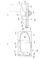
図6(a)は、第2のペダルに相当する麻痺側の足用の取付具である足ホルダー400を示す平面図、図6(b)は足ホルダー400を示す側面図である。
FIG. 6A is a plan view showing a
この足ホルダー400は、足固定部401と、基台402と、支持パイプ(嵌入支持部)403により構成されている。
The
足固定部401は、人間の足の足底,踵,足首に至る足固定部本体401aと、足甲を囲む鼻緒401bと、踵を囲む踵固定部401cとで構成されている。
基台402は、足固定部401の底面に、足幅方向及び長手方向に伸びる状態で形成されており、足固定部401とは回動連接具であるネジ404で回動可能に連接されている。ただし、前記回動は、2箇所のストッパ402aで回動角が制限されており、またカバー402bにより足固定部401が基台402から離間するのを制限されている。
更に、基台402の裏面には足と直交して(足幅方向に沿い)支持パイプ403が設けられており、この支持パイプ403には、クランク223a,223bの先端部の足用軸224a,224bが回転自在かつ緊密に嵌入することができるようになっていて、嵌入後は図示しないネジ等で抜けなくなっている。
The
The
Further, a
なお状況によっては足ホルダー400の代わりに、通常の靴や下駄やスリッパの底部に、足幅方向に沿い、支持パイプとして機能するパイプなどを取り付けた物を使用することもできる。靴等の底部に取り付けたパイプには、クランク223a,223bの先端部の足用軸224a,224bが回転自在かつ緊密に嵌入できるように、パイプの内径を設定しておく。
Depending on the situation, instead of the
つまり、足に履く足ホルダー(靴等)の底に、クランク223a,223bの先端部の足用軸224a,224bが緊密に嵌入することができる、支持パイプ403が形成されていてもよい。
That is, the
次に、上述した複合リハビリ機器10を用いてリハビリテーションを行う際の、使用動作状態を説明する。
Next, a use operation state when performing rehabilitation using the
片麻痺症状者の麻痺部が、例えば左腕であるときに、リハビリテーションを行う際の使用動作状態を、図7を参照して説明する。
図7に示すように、底板104の上に昇降台500を置く。この昇降台500は、縦,横,高さの寸法が、例えば、300mm、250mm,200mmとなっている台であり、台の向きを変えることにより高さを変えて椅子としても使用することができるものである。
また腕回転運動用のリハビリ機器αの右側クランク213aにはハンドル215aを取り付けておくが、左側クランク213bからはハンドル215bを取り外しておく。
When the hemiplegic symptom person is the left arm, for example, a use operation state when performing rehabilitation will be described with reference to FIG.
As shown in FIG. 7, the
A
片麻痺症状者Pの左腕の前腕に、前腕ホルダー300を取り付ける。次に、片麻痺症状者Pは、手すり棒106の内部に入り、昇降台500の上に座る。手すり棒106の内部に入る時には、図2に示すように手すり棒材106bを回動して開けて入るか、または、図1のスライド部材108aを右に移動させると手すり開閉部材106cの断端が現れるので、手すり開閉部材106cを蝶番部材108bで下方に折ると、手すり開閉部材106cの断端から蝶番部材108bまでが開くので、ここから入る。
The
そして、前腕ホルダー300の把持軸304aに設けた把持孔304bに手用軸214bを緊密に嵌入する。このようにすることにより、左側の前腕に取り付けられた前腕ホルダー300を、左側のクランク213bにより支持することができる。
Then, the
片麻痺症状者Pは、右手で右側のハンドル215aを握り、右足を右側のペダル225aの上に載せ、左足を左側のペダル225bの上に載せる。
The hemiplegic symptom P holds the
以上は左足の麻痺が軽度な場合であるが、重度の場合には左足を左側のペダル225bに安定して載せられない。この時にはペダル225bの代わりに、図6の足ホルダー400を用いることが好ましい。
足ホルダー400は、基台402の支持パイプ403に、足用軸224bを挿入嵌合して取り付ける。このとき人により異なる足の開角を補正するため、基台402に可変角度で取り付けられた足固定部401を、回動連接具であるネジ404を旋回中心として補正量に合わせて回転させる。また、麻痺した足を、踵固定部401cと鼻緒401bとで、足固定部401に固定する。
なお、足固定部401の爪先側の浮き防止は、基台402に設けたカバー402bで行い、足固定部401の旋回角度制限はストッパピン402aで行う。
The above is a case where the paralysis of the left foot is mild, but if it is severe, the left foot cannot be stably placed on the
The
Note that the toe side of the
右手でハンドル215aを握りクランク213aを回転させると、この回転力が左側のクランク213bに伝達されて、左側のクランク213bが回転する。また、ペダル225a、225bを漕いでクランク223a,223bを回転させると、この回転力が歯付きベルト230を介して左側のクランク213bに伝達されて、左側のクランク213bが回転する。
When the
このため、左側のクランク213bに支持された、前腕ホルダー300と、この前腕ホルダー300が取り付けられた左側の前腕が回転して、麻痺している左側の前腕・上腕・肩が連動した運動をする。また左側のクランク223bに支持された足ホルダー400も回転運動をする。
この場合、健常側の右腕及び両脚または片脚の力、つまり、片麻痺症状者P自身が自己の意志で動かした身体(手足)の力が、麻痺している左側の腕に伝達されて、麻痺している左側の腕の回転運動ができるため、左側の腕の回転運動はいわば自発的な運動になる。
このような自発的な運動は、機能回復訓練として効果的であり、前述した神経系の可塑化(脳神経の代替能力の獲得、神経の再生化、再組織化)を積極的に促すことができる。
For this reason, the
In this case, the power of the right arm and both legs or one leg on the healthy side, that is, the power of the body (limbs) that the hemiplegic symptom P itself moved at his own will be transmitted to the paralyzed left arm, Since the paralyzed left arm can rotate, the left arm rotates spontaneously.
Such spontaneous exercise is effective as functional recovery training, and can positively promote the plasticization of the nervous system described above (acquisition of cranial nerve alternative ability, nerve regeneration, reorganization). .
なお、図7に示す状態から、両足をペダル225a,225bから外し、右腕だけで回転力を発生させたり、右腕をハンドル215aから離し、右足だけで回転力を発生させたりすることもできる。
このように、健常側の身体の動きを変化させることによっても、身体や神経や脳に対する刺激が変化し、効果的な機能回復訓練ができる。
From the state shown in FIG. 7, it is also possible to remove both feet from the
Thus, by changing the movement of the healthy body, the stimulation to the body, nerves and brain changes, and effective function recovery training can be performed.
更に、図4に示すように、クランク213aとクランク213bの回転位相角度差を、180度のみならず、+90度、−90度、0度と変化させることによっても、回転運動をする際に左右の腕の回転位相位置の関係が変化するため、身体や神経や脳に対する刺激が変化し、効果的な機能回復訓練ができる。
Furthermore, as shown in FIG. 4, the rotational phase angle difference between the
上述したのは、左腕が麻痺している場合であるが、右腕が麻痺している場合には、腕回転運動用のリハビリ機器αの右側クランク213aからはハンドル215aを取り外しておくが、左側クランク213bにはハンドル215bを取り付けておくとともに、右側の前腕に前腕ホルダー300を取り付ける。なお、左用の前腕ホルダー300を右用に変更するには、前述したように、2本の取付ネジ304dを外した後、現在左側から支えている把持軸304aを右側から支えるように、把持板304cを左右に180°入れ替えて取付ネジ304dを締めつければ良い。
そして、上述した左腕の回復訓練と同様にして、右腕の回復訓練を行うことができる。
The above is a case where the left arm is paralyzed, but when the right arm is paralyzed, the
Then, the recovery training for the right arm can be performed in the same manner as the recovery training for the left arm described above.
片麻痺症状者の麻痺部が、例えば左脚であるときに、リハビリテーションを行う際の使用動作状態を、図8を参照して説明する。
図8に示すように、底板104の上に昇降台500を置く。また脚回転運動用のリハビリ機器βの右側クランク223aにはペダル225aを取り付けておくが、左側クランク223bからはペダル225bを取り外しておく。
When the hemiplegic symptom person is a left leg, for example, a use operation state when performing rehabilitation will be described with reference to FIG.
As shown in FIG. 8, the
片麻痺症状者Pは、手すり棒106の内部に入り、昇降台500の上に座る。次に、片麻痺症状者Pの左脚の足に、足ホルダー400を取り付ける。
The hemiplegic symptom person P enters the
そして、足ホルダー400の支持パイプ403に、クランク223bの先端部の足用軸224bを緊密に嵌入して図示しないネジ等でロックして抜けなくする。このようにすることにより、左側の足に取り付けられた足ホルダー400を、左側のクランク223bにより支持することができる。
Then, the
片麻痺症状者Pは、右手で右側のハンドル215aを握り、右足を右側のペダル225aの上に載せる。
右側のペダル225aを漕いでクランク223aを回転させると、この回転力が左側のクランク223bに伝達されて、左側のクランク223bが回転する。また、右及び可能な範囲で左の手でハンドル215a,215bを握りクランク213a,213bを回転させると、この回転力が歯付きベルト230を介して左側のクランク223bに伝達されて、左側のクランク223bが回転する。
The hemiplegic symptom P holds the
When the
このため、左側のクランク223bに支持された、足ホルダー400と、この足ホルダー400が取り付けられた左側の足が回転して、麻痺している左側の足・脚が回転運動する。
この場合、健常側の右腕及び右脚の力、つまり、片麻痺症状者P自身が自己の意志で動かした身体(手足)の力が、麻痺している左側の足・脚に伝達されて、麻痺している左側の足・脚の回転運動ができるため、左側の足・脚の回転運動はいわば自発的な運動になる。
このような自発的な運動は、機能回復訓練として効果的であり、前述した神経系の可塑化(脳神経の代替能力の獲得、神経の再生化、再組織化)を積極的に促すことができる。
Therefore, the
In this case, the power of the right arm and right leg on the healthy side, that is, the power of the body (limbs) that the hemiplegic symptom P itself moved by his / her own will be transmitted to the paralyzed left leg / leg, Because the left leg and leg that are paralyzed can rotate, the left leg and leg rotate spontaneously.
Such spontaneous exercise is effective as functional recovery training, and can positively promote the plasticization of the nervous system described above (acquisition of cranial nerve alternative ability, nerve regeneration, reorganization). .
なお、図8に示す状態から、両手をハンドル215a,215bから外し、右脚だけで回転力を発生させたり、右脚をペダル225aから離し、右手だけで回転力を発生させたりすることもできる。
このように、健常側の身体の動きを変化させることによっても、身体や神経や脳に対する刺激が変化し、効果的な機能回復訓練ができる。
In addition, from the state shown in FIG. 8, both hands can be removed from the
Thus, by changing the movement of the healthy body, the stimulation to the body, nerves and brain changes, and effective function recovery training can be performed.
更に、クランク223aとクランク223bの回転位相角度差を、180度のみならず、+90度、−90度、0度と変化させることによっても、回転運動をする際に左右の足・脚の回転位相位置の関係が変化するため、身体や神経や脳に対する刺激が変化し、効果的な機能回復訓練ができる。
Further, by changing the rotational phase angle difference between the
上述したのは、左脚が麻痺している場合であるが、右脚が麻痺している場合には、脚回転運動用のリハビリ機器βの右側クランク223aからはペダル225aを取り外しておくが、左側クランク223bにはペダル225bを取り付けておくとともに、右側の足に足ホルダー400を取り付ける。
そして、上述した左脚の回復訓練と同様にして、右脚の回復訓練を行うことができる。
The above is the case where the left leg is paralyzed, but when the right leg is paralyzed, the
Then, the recovery training for the right leg can be performed in the same manner as the recovery training for the left leg described above.
片麻痺症状者のリハビリテーションが進み麻痺が軽減した場合や、運動機能低下を呈する症状者が運動機能を維持するために利用したり、高齢者など身体機能能力が衰えた人が健康度を向上するために利用したりする場合には、図9に示すように、左右の手でハンドル215a,215bを握ると共に、左右の足をペダル225a,225bに載せて、回転運動をすることもできる。
When rehabilitation of persons with hemiplegic symptoms progresses and paralysis is reduced, those with symptoms of motor function decline are used to maintain motor function, and those with decreased physical function ability such as elderly people improve health For example, as shown in FIG. 9, the
昇降運動をするときには、図7〜図9に二点鎖線で示すように、昇降台500の向きを変更してその高さを最適な高さとし、片麻痺症状者Pは手すり棒106に掴まりつつ、底板104と昇降台500との間で、昇降移動運動をすることができる。
When performing the up-and-down movement, as shown by a two-dot chain line in FIGS. 7 to 9, the direction of the
立ち・座り運動をするときには、図7〜図9に実線で示すように、昇降台500の向きを変更してその高さを椅子として最適な高さとし、片麻痺症状者Pは手すり棒106に掴まりつつ、椅子としての昇降台500に腰掛けたり、立ち上がったりする立ち・座り運動をすることができる。
When standing or sitting, as shown by solid lines in FIGS. 7 to 9, the direction of the
歩行運動をするときには、片麻痺症状者は手すり棒106の外側(外周側)に出て、手すり棒106に掴まりつつ、手すり棒106に沿い周回して歩行運動をすることができる。この場合、手すり棒106が、腕回転運動用のリハビリ機器α、脚回転運動用のリハビリ機器β、昇降台500などを包含したループ状になっているため、ループの外側では手すり棒106を持ちながら身体の方向転換をすることなく連続的に歩行運動(歩行訓練)をすることができる。
When walking, a person with hemiplegia can go out of the handrail bar 106 (outside) and grab on the
上述した複合リハビリ機器10は、連続歩行用のリハビリ機器100と回転運動用のリハビリ機器200とを合体させているため、コンパクトな構成機器となっている。
このため、病院やリハビリ施設で使用する場合のみならず、設置スペースが制限される自宅においても使用することができる。
The
For this reason, it can be used not only in hospitals and rehabilitation facilities but also in homes where installation space is limited.
また、前腕ホルダー300を用いることにより腕回転運動用のリハビリ機器αによる腕回転運動が容易にでき、足ホルダー400を用いることにより脚回転運動用のリハビリ機器βによる脚回転運動が容易にでき、ループ状の手すり棒106に沿い連続的な歩行訓練ができるため、介助者等による介助を受けることなく、片麻痺症状者が自分自身の健常側の身体能力を用いることによって、自発的に複数のリハビリテーションを一人で(単独で)行うことができる。
Further, by using the
なお上記実施例では、複合リハビリ機器10として、連続歩行用のリハビリ機器100と回転運動用のリハビリ機器200を合体させた複合機器となっているが、連続歩行用のリハビリ機器100や回転運動用のリハビリ機器200をそれぞれ単独の機器として構成することも可能である。
In the above embodiment, the
また回転運動用のリハビリ機器200としては、腕回転運動用のリハビリ機器αと脚回転運動用のリハビリ機器βの両方を備えたものとしたが、腕回転運動用のリハビリ機器αと脚回転運動用のリハビリ機器βの一方のみを備えたものとすることも可能である。
In addition, the
以上、本発明の装置(複合リハビリ機器10)によると、片麻痺症状者(患者)が健常な腕と麻痺した腕との連携、また健常な脚と麻痺した脚との連携、更には腕と脚との連携ができることを詳述し、さらに機能的には昇降運動、立ち・座り運動、歩行運動等が可能であることを示した。
特に腕・脚の連携は関連しているが、他の運動との連携による効果は定かではない。
しかしながら本装置を用いて片麻痺症状者に操作を依頼したところ、腕・脚の関連だけでなく、例えば脚回転運動用のリハビリ機器βを用いた後、立ち・座り運動や歩行運動を行ったところ、通常の病院での訓練に比べ、その後の歩行や連携動作に滑らかさが顕著に増加したことが見えたと共に、患者本人も「身体が動く」ということが感想であった。
とはいえ一気に健常者になるものではないが、その要点として、異種作業を複数同時に行うことの他、作業と作業との間の時間を短くすることで、その効果が著しい。
即ち、作業を終えても短時間で次の作業に移れば、前作業による筋肉の活性化に加え、前作業と次の作業による「可塑性」が活発に連動し、相乗効果が現実に期待できる。
事実、作業と作業の間に休憩的時間を設けると、殆ど相乗的効果が見えないどころか、長時間(例えば何カ月)経ても初期状態を維持している患者が多い。
当初に述べた通り、病院でのリハビリは種類が少ない上、作業間の時間が長い。
それに比べ本装置は短時間で次の作業に移ることができ、更に手(腕)・足(脚)の関連作業を連動或いは短時間で連動させるようにしたので、患者を飽きさせることなく「可塑性」を含め高い効果が期待できる。
As described above, according to the apparatus of the present invention (composite rehabilitation device 10), a hemiplegic symptom (patient) cooperates with a healthy arm and a paralyzed arm, cooperates with a healthy leg and a paralyzed leg, and further It was explained in detail that it can be linked with the legs, and functionally, it was shown that it could move up and down, stand and sit, and walk.
In particular, the cooperation between arms and legs is related, but the effects of cooperation with other exercises are uncertain.
However, when this device was used to request operation for a hemiplegic symptom, not only the arm / leg relationship, but also, for example, using a rehabilitation device β for leg rotation exercise, standing / sitting exercise and walking exercise were performed. However, compared with the training in a normal hospital, it was seen that the smoothness was significantly increased in the subsequent walking and cooperation, and the patient himself was also "immediately moving".
However, although it does not become a healthy person at a stretch, the effect is remarkable by shortening the time between work in addition to simultaneously performing multiple different kinds of work.
In other words, if you move to the next task in a short time after finishing the work, in addition to activating the muscles from the previous work, the “plasticity” from the previous work and the next work will be actively linked, and a synergistic effect can be expected in reality. .
In fact, if a break is provided between tasks, many patients maintain their initial state over a long period of time (for example, several months), rather than seeing a synergistic effect.
As stated at the beginning, there are few types of rehabilitation in hospitals and the time between operations is long.
Compared to this, this device can move to the next work in a short time, and the related work of hands (arms) and feet (legs) is linked or linked in a short time. High effects including “plasticity” can be expected.
<装置全体の構成効果>
手すり棒からなるループ内に複数のリハビリ機器を包含し、手及び足のリハビリ機器も可能な限り関連づけて操作できるようにしたので、
(1)手足のリハビリ運動を同時或いは共働しながら自発的に行うことができ、
(2)異種のリハビリ機器に、短時間で移動できる。
上記の(1)、(2)が実現できるので、脳の可塑化が期待できると共に、少スペースで安価な複合リハビリ機器が実現できる。
<Configuration effect of the entire device>
Because we included multiple rehabilitation devices in a loop of handrail bars, we were able to operate hand and foot rehabilitation devices as much as possible.
(1) Can perform voluntary rehabilitation exercises simultaneously or jointly,
(2) It can be moved to different types of rehabilitation equipment in a short time.
Since (1) and (2) described above can be realized, it is possible to expect plasticization of the brain, and it is possible to realize an inexpensive composite rehabilitation device in a small space.
10 複合リハビリ機器
100 連続歩行用のリハビリ機器
106 手すり棒
200 回転運動用のリハビリ機器
201 本体支柱(本体支持部)
300 前腕ホルダー
400 足ホルダー
500 昇降台
DESCRIPTION OF
300
Claims (15)
基端部には、前記回転軸の端部に緊密に嵌合する多角形の嵌合孔が形成されており、当該嵌合孔に前記回転軸の一方の端部を嵌合することにより前記回転軸に組み付けられ、しかも、前記回転軸の一方の端部に対する前記嵌合孔の回転位相位置をずらすことにより、前記回転軸に対する回転位相位置を変化させることができる第1の手用のクランクと、
前記回転軸に対して略平行となる状態で、第1の手用のクランクの先端部に設けた第1の手用軸と、
前記第1の手用軸に回転自在に組み付けられた第1のハンドルと、
基端部には、前記回転軸の端部に緊密に嵌合する多角形の嵌合孔が形成されており、当該嵌合孔に前記回転軸の他方の端部を嵌合することにより前記回転軸に組み付けられ、しかも、前記回転軸の他方の端部に対する前記嵌合孔の回転位相位置をずらすことにより、前記回転軸に対する回転位相位置を変化させることができる第2の手用のクランクと、
前記回転軸に対して略平行となる状態で、第2の手用のクランクの先端部に設けた第2の手用軸と、
前記第2の手用軸に回転自在に組み付けられた第2のハンドルと、
を有することを特徴とする腕回転運動用のリハビリ機器。 A rotating shaft that is rotatably supported with respect to the main body support portion, and that has both ends in the shape of a polygonal column,
The base end is formed with a polygonal fitting hole that fits tightly into the end of the rotating shaft, and by fitting one end of the rotating shaft into the fitting hole, A first hand crank that is assembled to the rotating shaft and can change the rotating phase position with respect to the rotating shaft by shifting the rotating phase position of the fitting hole with respect to one end of the rotating shaft. When,
A first hand shaft provided at a tip portion of a first hand crank in a state of being substantially parallel to the rotation shaft;
A first handle rotatably assembled to the first hand shaft;
The base end portion is formed with a polygonal fitting hole that fits tightly into the end portion of the rotating shaft, and the other end portion of the rotating shaft is fitted into the fitting hole. A second hand crank that is assembled to the rotation shaft and can change the rotation phase position with respect to the rotation shaft by shifting the rotation phase position of the fitting hole with respect to the other end of the rotation shaft. When,
A second hand shaft provided at a tip portion of a second hand crank in a state of being substantially parallel to the rotation shaft;
A second handle rotatably assembled to the second hand shaft;
A rehabilitation device for rotating the arm, characterized by comprising:
前記回転軸の両端部の形状は、前記嵌合孔に緊密に嵌合する複数の辺を有する多角柱形状になっていることを特徴とする請求項1の腕回転運動用のリハビリ機器。 The shape of the fitting hole is a regular polygon,
2. The rehabilitation device for arm rotation movement according to claim 1, wherein the shape of both ends of the rotation shaft is a polygonal column shape having a plurality of sides closely fitted in the fitting hole.
基端部には、前記回転軸の端部に緊密に嵌合する多角形の嵌合孔が形成されており、当該嵌合孔に前記回転軸の一方の端部を嵌合することにより前記回転軸に組み付けられ、しかも、前記回転軸の一方の端部に対する前記嵌合孔の回転位相位置をずらすことにより、前記回転軸に対する回転位相位置を変化させることができる第1の足用のクランクと、
前記回転軸に対して略平行となる状態で、第1の足用のクランクの先端部に設けた第1の足用軸と、
前記第1の足用軸に回転自在に組み付けられた第1のペダルと、
基端部には、前記回転軸の端部に緊密に嵌合する多角形の嵌合孔が形成されており、当該嵌合孔に前記回転軸の他方の端部を嵌合することにより前記回転軸に組み付けられ、しかも、前記回転軸の他方の端部に対する前記嵌合孔の回転位相位置をずらすことにより、前記回転軸に対する回転位相位置を変化させることができる第2の足用のクランクと、
前記回転軸に対して略平行となる状態で、第2の足用のクランクの先端部に設けた第2の足用軸と、
第2の足用軸に回転自在に組み付けられた第2のペダルと、
を有することを特徴とする脚回転運動用のリハビリ機器。 A rotating shaft that is rotatably supported with respect to the main body support portion, and that has both ends in the shape of a polygonal column,
The base end is formed with a polygonal fitting hole that fits tightly into the end of the rotating shaft, and by fitting one end of the rotating shaft into the fitting hole, A crank for a first foot that is assembled to a rotating shaft and can change the rotating phase position with respect to the rotating shaft by shifting the rotating phase position of the fitting hole with respect to one end of the rotating shaft. When,
A first foot shaft provided at a tip portion of a first foot crank in a state of being substantially parallel to the rotation shaft;
A first pedal rotatably assembled to the first foot shaft;
The base end portion is formed with a polygonal fitting hole that fits tightly into the end portion of the rotating shaft, and the other end portion of the rotating shaft is fitted into the fitting hole. A crank for a second foot that is assembled to the rotating shaft and can change the rotating phase position with respect to the rotating shaft by shifting the rotating phase position of the fitting hole with respect to the other end of the rotating shaft. When,
A second foot shaft provided at the tip of the second foot crank in a state of being substantially parallel to the rotation shaft;
A second pedal rotatably assembled to the second foot shaft;
A rehabilitation device for rotating a leg, characterized by comprising:
前記回転軸の両端部の形状は、前記嵌合孔に緊密に嵌合する複数の辺を有する多角柱形状になっていることを特徴とする請求項4の脚回転運動用のリハビリ機器。 The shape of the fitting hole is a regular polygon,
The rehabilitation device for leg rotation motion according to claim 4, wherein the shape of both ends of the rotation shaft is a polygonal column shape having a plurality of sides closely fitted in the fitting hole.
請求項4に記載の脚回転運動用のリハビリ機器と、
前記腕回転運動用のリハビリ機器の回転軸と前記脚回転運動用のリハビリ機器の回転軸との間で回転力を伝達する回転力伝達機構と、
を有することを特徴とするリハビリ機器。 A rehabilitation device for arm rotation movement according to claim 1;
Rehabilitation equipment for leg rotation movement according to claim 4;
A rotational force transmission mechanism for transmitting rotational force between the rotational axis of the rehabilitation device for arm rotational motion and the rotational axis of the rehabilitation device for leg rotational motion;
A rehabilitation device characterized by comprising:
請求項1乃至請求項13の何れか一項に記載のリハビリ機器とを備え、
前記手すり棒の内側に、少なくとも請求項1乃至請求項13の何れか一項に記載のリハビリ機器が配置されていることを特徴とする複合リハビリ機器。 A rehabilitation device for continuous walking composed of a plurality of support bars and a loop-shaped handrail bar connected to the top of the plurality of support bars and supported horizontally;
A rehabilitation device according to any one of claims 1 to 13,
A rehabilitation device according to claim 1, wherein at least the rehabilitation device according to claim 1 is arranged inside the handrail bar.
Priority Applications (1)
| Application Number | Priority Date | Filing Date | Title |
|---|---|---|---|
| JP2010091194A JP2011217992A (en) | 2010-04-12 | 2010-04-12 | Rehabilitation apparatus |
Applications Claiming Priority (1)
| Application Number | Priority Date | Filing Date | Title |
|---|---|---|---|
| JP2010091194A JP2011217992A (en) | 2010-04-12 | 2010-04-12 | Rehabilitation apparatus |
Publications (1)
| Publication Number | Publication Date |
|---|---|
| JP2011217992A true JP2011217992A (en) | 2011-11-04 |
Family
ID=45035720
Family Applications (1)
| Application Number | Title | Priority Date | Filing Date |
|---|---|---|---|
| JP2010091194A Withdrawn JP2011217992A (en) | 2010-04-12 | 2010-04-12 | Rehabilitation apparatus |
Country Status (1)
| Country | Link |
|---|---|
| JP (1) | JP2011217992A (en) |
Cited By (3)
| Publication number | Priority date | Publication date | Assignee | Title |
|---|---|---|---|---|
| CN102940559A (en) * | 2012-12-07 | 2013-02-27 | 付风生 | Mechanical hand of upper limb rehabilitation training robot |
| CN103301004A (en) * | 2012-03-13 | 2013-09-18 | 吕召霞 | Pelvic bending and knee bending training device |
| WO2019045051A1 (en) * | 2017-08-31 | 2019-03-07 | 国立大学法人 鹿児島大学 | Hemiplegic forearm function recovery training device and method |
-
2010
- 2010-04-12 JP JP2010091194A patent/JP2011217992A/en not_active Withdrawn
Cited By (6)
| Publication number | Priority date | Publication date | Assignee | Title |
|---|---|---|---|---|
| CN103301004A (en) * | 2012-03-13 | 2013-09-18 | 吕召霞 | Pelvic bending and knee bending training device |
| CN103301004B (en) * | 2012-03-13 | 2014-12-31 | 吕召霞 | Pelvic bending and knee bending training device |
| CN102940559A (en) * | 2012-12-07 | 2013-02-27 | 付风生 | Mechanical hand of upper limb rehabilitation training robot |
| WO2019045051A1 (en) * | 2017-08-31 | 2019-03-07 | 国立大学法人 鹿児島大学 | Hemiplegic forearm function recovery training device and method |
| CN111093588A (en) * | 2017-08-31 | 2020-05-01 | 国立大学法人鹿儿岛大学 | Training device and method for recovering function of forearm of hemiplegia |
| US11583463B2 (en) | 2017-08-31 | 2023-02-21 | Kagoshima University | Hemiplegic forearm function recovery training device and method |
Similar Documents
| Publication | Publication Date | Title |
|---|---|---|
| JP5259629B2 (en) | Training equipment for the disabled | |
| US9549866B2 (en) | Rehabilitative training devices for use by stroke patients | |
| CN110664584B (en) | Rehabilitation training bed | |
| JPH09505743A (en) | Stretch therapy equipment for maintaining good physical fitness, rehabilitation and treatment | |
| EP1983960A1 (en) | Orthopaedic apparatus for walking and rehabilitating motion-injured persons | |
| CN108888476B (en) | Medical hand-cranking type leg rehabilitation equipment | |
| JP2012005523A (en) | Rehabilitation device for rotational movement of upper limb | |
| US20110071441A1 (en) | Orthopedic rehabilitation mechanism employing a foot support having a first portion and a second portion configured to rotate with respect to one another | |
| JP2011217992A (en) | Rehabilitation apparatus | |
| JP2011217993A (en) | Rehabilitation apparatus | |
| Wu et al. | A novel cable-driven robotic training improves locomotor function in individuals post-stroke | |
| CN109350461A (en) | Cerebral Infarction Patients lower limb rehabilitation training device | |
| CN112546568B (en) | Orthopedic patient rehabilitation training method using medical rehabilitation equipment | |
| CN212522862U (en) | Orthopedics that possesses function of tempering low limbs helps capable ware | |
| JP3081786U (en) | Manual lower limb joint bending device | |
| JP2012005524A (en) | Three-dimensional stepper | |
| US20230285216A1 (en) | Rehabilitative wrist training device for use by stroke patients | |
| Hensel et al. | Neurorehabilitation: strategies of lower extremities restoration | |
| JP2012005522A (en) | Apparatus for leg slide exercise | |
| CN205459690U (en) | Portable knee joint rehabilitation trains ware | |
| JPH0517064Y2 (en) | ||
| JP4049530B2 (en) | Therapeutic instrument | |
| CZ35258U1 (en) | Rehabilitation sensor device | |
| CZ20211A3 (en) | Rehabilitation sensor device | |
| JP2007330730A (en) | Device for recovering affected part function or strengthening human body function |
Legal Events
| Date | Code | Title | Description |
|---|---|---|---|
| A300 | Withdrawal of application because of no request for examination |
Free format text: JAPANESE INTERMEDIATE CODE: A300 Effective date: 20130702 |