JP2011143834A - Vehicle - Google Patents
Vehicle Download PDFInfo
- Publication number
- JP2011143834A JP2011143834A JP2010006492A JP2010006492A JP2011143834A JP 2011143834 A JP2011143834 A JP 2011143834A JP 2010006492 A JP2010006492 A JP 2010006492A JP 2010006492 A JP2010006492 A JP 2010006492A JP 2011143834 A JP2011143834 A JP 2011143834A
- Authority
- JP
- Japan
- Prior art keywords
- pipe
- vehicle
- main frame
- auxiliary
- fuel tank
- Prior art date
- Legal status (The legal status is an assumption and is not a legal conclusion. Google has not performed a legal analysis and makes no representation as to the accuracy of the status listed.)
- Pending
Links
Images


Classifications
-
- B—PERFORMING OPERATIONS; TRANSPORTING
- B62—LAND VEHICLES FOR TRAVELLING OTHERWISE THAN ON RAILS
- B62K—CYCLES; CYCLE FRAMES; CYCLE STEERING DEVICES; RIDER-OPERATED TERMINAL CONTROLS SPECIALLY ADAPTED FOR CYCLES; CYCLE AXLE SUSPENSIONS; CYCLE SIDE-CARS, FORECARS, OR THE LIKE
- B62K5/00—Cycles with handlebars, equipped with three or more main road wheels
- B62K5/01—Motorcycles with four or more wheels
Landscapes
- Engineering & Computer Science (AREA)
- Mechanical Engineering (AREA)
- Cooling, Air Intake And Gas Exhaust, And Fuel Tank Arrangements In Propulsion Units (AREA)
- Automatic Cycles, And Cycles In General (AREA)
Abstract
Description
本発明は、車両、特に燃料タンク等の大型補機の搭載性を改善した車両に関する。 The present invention relates to a vehicle, and more particularly to a vehicle with improved mountability of a large auxiliary machine such as a fuel tank.
乗員が座るシートを支えるリヤパイプの下に、燃料タンク等の大型補機を配置することが知られている(例えば、特許文献1(図3、図7)参照。)。 It is known to dispose a large auxiliary machine such as a fuel tank under a rear pipe that supports a seat on which an occupant sits (see, for example, Patent Document 1 (FIGS. 3 and 7)).
特許文献1の図7に、車体フレームの斜視図が示されており、左右の上部フレームパイプ(19)(括弧付き数字は、特許文献1に記載された符号を示す。以下同様)が、車体長手方向に延ばされ、この上部フレームパイプ(19)の後部が、斜めの後部支持パイプ(24)で支持されている。 FIG. 7 of Patent Document 1 shows a perspective view of the vehicle body frame, and the left and right upper frame pipes (19) (the numbers in parentheses indicate the symbols described in Patent Document 1. The same applies hereinafter). It extends in the longitudinal direction, and the rear portion of the upper frame pipe (19) is supported by an oblique rear support pipe (24).
特許文献1の図3に示されるように、上部フレームパイプ(19)の後部は、リヤパイプと呼ばれ、シート(6)を支える部材である。このリヤパイプの下方に、燃料タンク(81)が配置されている。この燃料タンク(81)の下方に示されている、斜めの部材は、図7に示される後部支持パイプ(24)である。 As shown in FIG. 3 of Patent Document 1, the rear portion of the upper frame pipe (19) is called a rear pipe and is a member that supports the seat (6). A fuel tank (81) is disposed below the rear pipe. The diagonal member shown below the fuel tank (81) is the rear support pipe (24) shown in FIG.
リヤパイプと後部支持パイプ(24)との間のスペースに、燃料タンク(81)が配置され、スペースの有効活用を図ることができる。
燃料タンク(81)は、取付け方向が、図3の表裏方向であるため、リヤパイプの下面と後部支持パイプ(24)の上面との間隔より、高さ寸法が小さくなっている。
A fuel tank (81) is disposed in the space between the rear pipe and the rear support pipe (24), so that the space can be effectively used.
Since the mounting direction of the fuel tank (81) is the front and back direction in FIG. 3, the height dimension is smaller than the distance between the lower surface of the rear pipe and the upper surface of the rear support pipe (24).
この構造であれば、燃料タンク(81)の大型化が求められた場合には、後部支持パイプ(24)を下げる必要がある。しかし、車両の構造上、後部支持パイプ(24)を下げることができないことは、少なくない。 With this structure, when the fuel tank (81) needs to be enlarged, the rear support pipe (24) needs to be lowered. However, the rear support pipe (24) cannot often be lowered due to the structure of the vehicle.
そこで、後部支持パイプ(24)を下げることなく、リヤパイプの下面と後部支持パイプ(24)の上面との間隔を遙かに超えた大型の燃料タンクを取付けることができる構造が望まれる。燃料タンクを例に説明したが、リヤパイプの下に、その他の補機類が置かれる場合もある。 Therefore, a structure that can attach a large fuel tank that far exceeds the distance between the lower surface of the rear pipe and the upper surface of the rear support pipe (24) without lowering the rear support pipe (24) is desired. Although the fuel tank has been described as an example, other auxiliary equipment may be placed under the rear pipe.
本発明は、後部支持パイプを下げることなしに、リヤパイプの下方に燃料タンク等の大型の補機類を取付けることができる構造の車両を提供することを課題とする。 It is an object of the present invention to provide a vehicle having a structure in which large auxiliary equipment such as a fuel tank can be attached below the rear pipe without lowering the rear support pipe.
請求項1に係る発明は、車両前後方向へ延びるメインフレームと、このメインフレームの後部上部から車両後方へ延びる左右一対のリヤパイプと、これらのリヤパイプと前記メインフレームとに渡され前記リヤパイプを補強する左右のリヤサブパイプと、前記メインフレームの後方に配置される燃料タンク、エアクリーナ等の補機類とを有する車両において、
前記左右のリヤサブパイプのうちの一方のリヤサブパイプは、前記左右のリヤパイプのうちの一方のリヤパイプと前記メインフレームとに固着され、他方のリヤサブパイプは、他方のリヤパイプと前記メインフレームとに着脱可能に取付けられていることを特徴とする。
According to the first aspect of the present invention, a main frame extending in the vehicle front-rear direction, a pair of left and right rear pipes extending from the rear upper part of the main frame to the rear of the vehicle, and the rear pipe and the main frame are passed to reinforce the rear pipe. In a vehicle having left and right rear sub-pipes and auxiliary equipment such as a fuel tank and an air cleaner disposed behind the main frame,
One of the left and right rear sub pipes is fixed to one of the left and right rear pipes and the main frame, and the other rear sub pipe is detachably attached to the other rear pipe and the main frame. It is characterized by.
請求項2に係る発明では、他方のリヤサブパイプは、車幅方向外側に外れるように形成され、車体側方からボルトで締結されることを特徴とする。 The invention according to claim 2 is characterized in that the other rear sub-pipe is formed so as to be disengaged outward in the vehicle width direction and is fastened with a bolt from the side of the vehicle body.
請求項3に係る発明では、一方のリヤサブパイプは、湾曲部が車両平面視で一方のリヤパイプより車体中心側に位置するように車幅方向内側に湾曲形成され、このような湾曲部に補機類を支持する補機類支持部の少なくとも1個が設けられていることを特徴とする。 In the invention according to claim 3, one of the rear sub-pipes is curved inward in the vehicle width direction so that the curved portion is positioned on the vehicle body center side of the one rear pipe in plan view of the vehicle. At least one of auxiliary equipment support portions for supporting the above is provided.
請求項4に係る発明では、一方のリヤサブパイプに、補機類の一方の側面を覆う第1補機カバーが取付けられ、
他方のリヤサブパイプに、補機類の他方の側面、補機類の底面、後面の少なくとも2つを覆う第2補機カバーが取付けられ、
この第2補機カバーに第1補機カバーを合わせることで、補機類をカバーするようにしたことを特徴とする。
In the invention which concerns on Claim 4, the 1st auxiliary machine cover which covers one side surface of auxiliary machinery is attached to one rear subpipe,
A second auxiliary cover that covers at least two of the other side surface of the auxiliary machinery, the bottom surface of the auxiliary machinery, and the rear surface is attached to the other rear sub pipe.
The first auxiliary machine cover is combined with the second auxiliary machine cover to cover the auxiliary machines.
請求項5に係る発明では、メインフレームは、左右一対のメインフレームからなり、この左のメインフレームの後部から右のメインフレームの後部へ車幅方向に延びるクロス部が渡され、このクロス部に燃料タンクの前部を支えるタンク支持穴が設けられ、
このタンク支持穴へ、燃料タンクから車両前方へ延びている突状ボスを嵌合することができるようにしたことを特徴とする。
In the invention according to claim 5, the main frame is composed of a pair of left and right main frames, and a cross portion extending in the vehicle width direction from the rear portion of the left main frame to the rear portion of the right main frame is passed to the cross portion. A tank support hole is provided to support the front of the fuel tank,
A projecting boss extending from the fuel tank to the front of the vehicle can be fitted into the tank support hole.
請求項6に係る発明では、湾曲部の車幅方向外側に、車両長手方向に延びる排気管又はこの排気管に接続される消音器が配置されることを特徴とする。 The invention according to claim 6 is characterized in that an exhaust pipe extending in the longitudinal direction of the vehicle or a silencer connected to the exhaust pipe is disposed outside the curved portion in the vehicle width direction.
請求項7に係る発明では、燃料タンクで発生する蒸発燃料を捕集するキャニスタが、第1補機カバーより車体中心側で、一方のリヤパイプに取付けられていることを特徴とする。 The invention according to claim 7 is characterized in that the canister for collecting the evaporated fuel generated in the fuel tank is attached to one of the rear pipes on the vehicle body center side from the first auxiliary machine cover.
請求項1に係る発明では、左右のリヤサブパイプ(従来技術の後部支持パイプに相当)のうちの一方のリヤサブパイプは、左右のリヤパイプ(従来技術の上部フレームパイプの「後部」に相当)のうちの一方のリヤパイプとメインフレーム(従来技術の上部フレームパイプに相当)とに固着され、他方のリヤサブパイプは、他方のリヤパイプとメインフレームとに着脱可能に取付けられている。 In the first aspect of the invention, one of the left and right rear sub pipes (corresponding to the rear support pipe of the prior art) is one of the left and right rear pipes (corresponding to the “rear part” of the upper frame pipe of the prior art). The other rear sub pipe is detachably attached to the other rear pipe and the main frame.
他方のリヤサブパイプを、メインフレーム及びリヤパイプから外すことで、燃料タンク等の大型の補機類をリヤパイプ下に挿入することができる。さらには、他方のリヤサブパイプに予め補機類を組付けておき、その後に、補機類と一体に他方のリヤサブパイプを、メインフレーム及びリヤパイプに取付けることが可能となる。
すなわち、本発明によれば、リヤサブパイプを下げることなしに、燃料タンク等の大型の補機類をリヤパイプの下に取付けることができる構造の車両が提供される。
By removing the other rear sub-pipe from the main frame and the rear pipe, large auxiliaries such as a fuel tank can be inserted under the rear pipe. Furthermore, it is possible to attach an auxiliary machine to the other rear sub-pipe in advance, and then attach the other rear sub-pipe to the main frame and the rear pipe integrally with the auxiliary machine.
That is, according to the present invention, there is provided a vehicle having a structure in which large auxiliary machines such as a fuel tank can be attached under the rear pipe without lowering the rear sub pipe.
請求項2に係る発明では、他方のリヤサブパイプは、車幅方向外側に外れるように形成され、車体側方からボルトで締結される。
ボルトを締めるだけで、他方のリヤサブパイプをメインフレーム及びリヤパイプに固定することができる。また、ボルトを緩めるだけで、他方のリヤサブパイプをメインフレーム及びリヤパイプから外し、大型の補機を車幅方向外側へ外すことができる。したがって、組付けが容易になり、補機類の組付けに係る工数を低減させることができる。
In the invention according to claim 2, the other rear sub-pipe is formed so as to be disengaged outward in the vehicle width direction and is fastened with a bolt from the side of the vehicle body.
The other rear sub-pipe can be fixed to the main frame and the rear pipe simply by tightening the bolt. Further, by simply loosening the bolt, the other rear sub pipe can be removed from the main frame and the rear pipe, and the large auxiliary machine can be removed outward in the vehicle width direction. Therefore, assembly becomes easy, and the man-hour concerning the assembly of auxiliary machinery can be reduced.
請求項3に係る発明では、一方のリヤサブパイプは、湾曲部が車両平面視で一方のリヤパイプより車体中心側に位置するように車幅方向内側に湾曲形成され、このような湾曲部に補機類を支持する補機類支持部の少なくとも1個が設けられている。
一方のリヤサブパイプは、湾曲部が車両平面視で一方のリヤパイプより車体中心側に位置するように車幅方向内側に湾曲形成されているため、平面視で、上位の一方のリヤパイプに妨げられることなく、一方のリヤサブパイプを視認することができる。このような一方のリヤサブパイプに補機類支持部が設けられているため、この補機類支持部に上方からボルトを挿入し、締結することが可能となる。
In the invention according to claim 3, one of the rear sub-pipes is curved inward in the vehicle width direction so that the curved portion is positioned on the vehicle body center side of the one rear pipe in plan view of the vehicle. There is provided at least one auxiliary equipment support part for supporting the machine.
One of the rear sub-pipes is curved inward in the vehicle width direction so that the curved portion is located on the vehicle body center side of the one rear pipe in a plan view of the vehicle, so that it is not obstructed by the upper rear pipe in the plan view. , One of the rear sub pipes can be visually recognized. Since such one rear sub-pipe is provided with an auxiliary equipment support portion, it is possible to insert a bolt into the auxiliary equipment support portion from above and fasten it.
請求項4に係る発明では、一方のリヤサブパイプに、補機類の一方の側面を覆う第1補機カバーが取付けられ、他方のリヤサブパイプに、補機類の他方の側面、補機類の底面、後面の少なくとも2つを覆う第2補機カバーが取付けられ、この第2補機カバーに第1補機カバーを合わせることで、補機類をカバーするようにした。
他方のリヤサブパイプに補機類を予め取付けると共に、第2補機カバーを予め取付けてることにより、他方のリヤサブパイプを、メインフレーム及びリヤパイプに取付けるだけで、補機カバーの取付けが完了する。すなわち、補機カバーの取付けが容易になる。
In the invention which concerns on Claim 4, the 1st auxiliary machine cover which covers one side of auxiliary machinery is attached to one rear sub pipe, The other side of auxiliary machinery, the bottom of auxiliary machinery, the other rear sub pipe, A second auxiliary machine cover that covers at least two of the rear surfaces is attached, and the first auxiliary machine cover is aligned with the second auxiliary machine cover to cover the auxiliary machines.
By attaching the auxiliary machinery to the other rear sub-pipe in advance and attaching the second auxiliary machinery cover in advance, the attachment of the auxiliary machinery cover is completed only by attaching the other rear sub-pipe to the main frame and the rear pipe. That is, the auxiliary machine cover can be easily attached.
請求項5に係る発明では、メインフレームは、左右一対のメインフレームからなり、この左のメインフレームの後部から右のメインフレームの後部へ車幅方向に延びるクロス部が渡され、このクロス部に燃料タンクの前部を支えるタンク支持穴が設けられている。そして、タンク支持穴へ、燃料タンクから車両前方へ延びている突状ボスを嵌合することができるようにした。
燃料タンクの前部は、突条ボスを車体側のタンク支持穴に嵌合するだけで、車体側に固定され、燃料タンクの取付け工数を低減することができる。
In the invention according to claim 5, the main frame is composed of a pair of left and right main frames, and a cross portion extending in the vehicle width direction from the rear portion of the left main frame to the rear portion of the right main frame is passed to the cross portion. A tank support hole for supporting the front portion of the fuel tank is provided. Then, a protruding boss extending from the fuel tank to the front of the vehicle can be fitted into the tank support hole.
The front portion of the fuel tank is fixed to the vehicle body by simply fitting the protrusion boss into the tank support hole on the vehicle body side, and the number of steps for mounting the fuel tank can be reduced.
請求項6に係る発明では、湾曲部の車幅方向外側に、車両長手方向に延びる排気管又はこの排気管に接続される消音器が配置される。
排気管又は消音器が、リヤサブパイプの車幅方向外側に配置されることが、少なくない。この場合は、排気管又は消音器が、車幅方向外側に張り出して、車幅が大きくなりやすい。この点、本発明によれば、車幅方向内側に湾曲させた湾曲部の車幅方向外側に、排気管又は消音器を配置するため、車幅の増加を抑えることができる。
In the invention which concerns on Claim 6, the silencer connected to the exhaust pipe extended in a vehicle longitudinal direction or this exhaust pipe is arrange | positioned on the vehicle width direction outer side of a curved part.
In many cases, the exhaust pipe or the silencer is disposed outside the rear sub pipe in the vehicle width direction. In this case, the exhaust pipe or the silencer protrudes outward in the vehicle width direction, and the vehicle width tends to increase. In this regard, according to the present invention, since the exhaust pipe or the silencer is disposed on the outer side in the vehicle width direction of the curved portion bent inward in the vehicle width direction, an increase in the vehicle width can be suppressed.
請求項7に係る発明では、燃料タンクで発生する蒸発燃料を捕集するキャニスタが、第1補機カバーより車体中心側で、一方のリヤパイプに取付けられている。
キャニスタが、一方のリヤパイプに取付けられているため、他方のリヤサブパイプと共に補機類を外したときに、キャニスタが外される心配はない。併せて、キャニスタは第1補機カバーでカバーされているため、外され難く、誤って外される心配はない。
In the invention according to claim 7, the canister for collecting the evaporated fuel generated in the fuel tank is attached to one of the rear pipes on the vehicle body center side from the first auxiliary machine cover.
Since the canister is attached to one rear pipe, there is no concern that the canister will be removed when the auxiliary equipment is removed together with the other rear sub-pipe. In addition, since the canister is covered with the first auxiliary machine cover, it is difficult to remove the canister and there is no fear of accidental removal.
また、一方のリヤパイプの下方に、排気管又は消音器ときには、排気管又は消音器の近傍にキャニスタが配置されることになる。排気管又は消音器の熱でキャニスタが暖まり、キャニスタのパージ効率が高まることが、期待される。 In addition, in the case of an exhaust pipe or a silencer below one of the rear pipes, a canister is disposed in the vicinity of the exhaust pipe or the silencer. It is expected that the canister is warmed by the heat of the exhaust pipe or the silencer and the purge efficiency of the canister is increased.
本発明の実施の形態を添付図に基づいて以下に説明する。なお、図面は符号の向きに見るものとする。 Embodiments of the present invention will be described below with reference to the accompanying drawings. The drawings are viewed in the direction of the reference numerals.
本発明の実施例を図面に基づいて説明する。
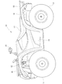
図1に示されるように、車両10は、車体の前部下部に前輪11を備え、この前輪11の上方にフロントフェンダ12を備え、車体の後部下部に後輪13を備え、この後輪13に上方にリヤフェンダ14を備え、前輪11の上方にステアリングハンドル15を備え、このステアリングハンドル15の前にフロント荷台16を備え、ステアリングハンドル15の後方にシート17及びリヤ荷台18を備えている、小型車両である。
Embodiments of the present invention will be described with reference to the drawings.
As shown in FIG. 1, the
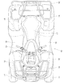
車両10は、図2に示されるように、ステアリングハンドル15とシート17との間に左右のステップフロア19、19を備えて、シート17に座った乗員の足をステップフォロア19、19に載せることができるようにした鞍乗り型不整地走行車両である。
As shown in FIG. 2, the
このような車両10の主要素である車体フレームの構造を、次に説明する。
図3に示すように、車体フレーム30は、車両前後方向に延びて後部が上方へ湾曲している、左右一対のメインフレーム31L、31R(Lは乗員から見て左を示し、Rは同右を示す添え字である。以下同じ)と、メインフレーム31L、31Rの前部から上方に延びるパイプ又はフレームで構成され前輪懸架装置を支持する、左右の前輪懸架支持部32L、32Rと、左の前輪懸架支持部32Lから右の前輪懸架支持部32Rへ車幅方向へ渡されている第1クロス部33と、左のメインフレーム31Lの後部から右のメインフレーム31Rの後部へ車幅方向へ渡されている第2クロス部34と、前端が第1クロス部33に取り外し可能に取付けられ、後端が第2クロス部34に取り外し可能に取付けられているアッパーテンションパイプ35と、メインフレーム31L、31Rの後部上部から車両後方へ延びる左右一対のリヤパイプ36L、36Rと、一方のメインフレーム31Lの後部中間部から斜めに一方のリヤパイプ36Lまで延ばされた一方のリヤサブパイプ37Lと、他方のメインフレーム31Rの後部中間部から斜めに一方のリヤパイプ36Rまで延ばされた一方のリヤサブパイプ37Rと、からなる。リヤサブパイプ37L、37Rは、リヤパイプ36L、36Rを補強する補強ステーである。
The structure of the body frame which is the main element of the
As shown in FIG. 3, the
これらの補強ステーを、更に詳しく説明する。
一方のリヤサブパイプ37Lは、一方のメインフレーム31L及び一方のリヤパイプ36Lに溶接で固定されている。
These reinforcing stays will be described in more detail.
One
他方のリヤサブパイプ37Rは、図3の4矢視図である図4に示すように、他方のメインフレーム31R及び他方のリヤパイプ36Rに取り外し可能に締結されている。
そのために、例えば、他方のメインフレーム31Rの中間部から車両後方へ前部ステー38を延ばす。この前部ステー38は面が車両側方から見ることのできるプレートである。
他方のリヤパイプ37Rの後部から下へ後部ステー39を延ばす。この後部ステー39は面が車両前方から見ることのできるプレートである。
The other
For this purpose, for example, the
The
L字形状を呈する他方のリヤサブパイプ37Rは、パイプ材の前端部に車幅方向に貫通するボルト穴41を有し、パイプ材の後端部に車体前後方向に貫通するボルト穴42を有する部材である。
そして、ボルト穴41、42にボルト43、44を通すことにより、他方のリヤサブパイプ37Rを、他方のメインフレーム31R及び他方のリヤパイプ36Rに取り外し可能に取付けることができる。
The other rear sub-pipe 37R having an L shape is a member having a
Then, by passing the
前部ステー38の面にリヤサブパイプ37Rの前端を当てると、リヤサブパイプ37Rに車幅方向の外力が作用した場合に、この外力は前部ステー38の面で効果的に支承される。
また、後部ステー39の前面にリヤサブパイプ37Rの後端を当てると、リヤサブパイプ37Rに車両後方へ外力が作用した場合に、この外力は後部ステー39の前面で効果的に支承される。
When the front end of the
Further, when the rear end of the
次に、リヤサブパイプ37L、37Rの形状を、図5に基づいて、補足説明する。
図5に示すように、右のリヤサブパイプ37Rの立ち下がり部分は、ほぼメインパイプ31Rに平行に下っている。
Next, the shapes of the
As shown in FIG. 5, the falling portion of the right
一方、左のリヤサブパイプ37Lは、車幅方向内側(車幅中心側)に張り出すように湾曲形成されている。この湾曲部46に左の補機類支持部47Lが、少なくとも1個、車幅方向内側に張り出すように設けられている。
この左の補機類支持部47Lに対応する右の補機類支持部47Rが、右のリヤサブパイプ37Rに設けられている。
On the other hand, the left
A right auxiliary
また、左のメインフレーム31Lの後部から右のメインフレーム31Rの後部に渡したクロス部(第2クロス部34)に、タンク支持穴48が設けられている。このタンク支持穴48は車両後方へ開口している。
Further, a
次に、補機類について説明する。
実施例では、燃料タンクを例に説明するが、補機類はエアクリーナ、バッテリや電装品などの大型の車載部品であれば種類は問わない。
図6に示すように、一方のリヤサブパイプ37Lには、燃料タンク50の左側面51をカバーする第1補機カバー52が取付けられている。
Next, auxiliary equipment will be described.
In the embodiment, a fuel tank will be described as an example. However, the auxiliary machine may be of any type as long as it is a large vehicle-mounted part such as an air cleaner, a battery, or an electrical component.
As shown in FIG. 6, the first
また、燃料タンク50は、燃料キャップ53及び燃料ポンプ54を備えている平面視略矩形の容器である。そして、燃料タンク50は、前面に車両前方へ延びる突状ボス55を備え、後面に右フランジ56R及び左フランジ56Lを備えている。
The
このような燃料タンク50は、右フランジ56Rと右の補機類支持部(図5符号47R)とをボルト57で締結することにより、他方のリヤサブパイプ37Rに予め取付けられる。
同時に燃料タンク50の右側面58、底面、後面59をカバーする第2補機カバー61も他方のリヤサブパイプ37Rに予め取付けられる。
Such a
At the same time, a second
次に、図7に示すように、燃料タンク50側の突条ボス55を、車体側のタンク支持穴48に挿入しつつ、左フランジ56Lを左の補機類支持部(図5符号47L)に載せ、上からボルト62を挿入し、締め付ける。これで、燃料タンク50は、前1箇所と後2箇所の合計3箇所で車体側に固定される。
結果、第1補機カバー52が第2補機カバー61と合体して、1個の補機カバーが完成し、この補機カバーで、燃料タンク50の底面、後面、左側面、右側面がカバーされる。
Next, as shown in FIG. 7, the
As a result, the first
さらに、燃料タンク50で発生する蒸発燃料を捕集するキャニスタ64が、第1補機カバー52より車体中心側で、ステー65により一方のリヤパイプ36Lに取付けられている。燃料タンク50で発生する蒸発燃料は、燃料タンク50から延びてキャニスタ64の前部に接続されるチャージパイプ67により、キャニスタ64に捕集される。そして、キャニスタ64の前部から車両前方へ向かって延ばされるパージパイプ68を通じて、蒸発燃料が適宜エンジンの吸気系へ送られる。また、キャニスタ64の後面からドレーンパイプ69が延ばされ、大気に開放される。
更には、燃料ポンプ54から、燃料供給パイプ71が、キャニスタ64の車幅右側方を通り、左のリヤパイプ36Lの車幅右側方を通ってエンジンに向かう。
Further, a
Furthermore, from the
また、図8に示されるように、湾曲部46の車幅方向外側に、車両長手方向に延びる排気管又はこの排気管に接続される消音器66が配置される。
Further, as shown in FIG. 8, an exhaust pipe extending in the vehicle longitudinal direction or a
以上の構成からなる車両10の後部構造の作用を次に述べる。
図4に示すように、他方のリヤサブパイプ37Rを、メインフレーム31R及びリヤパイプ36Rから外すことで、燃料タンク等の大型の補機類をリヤパイプ36R下に挿入することができる。
The operation of the rear structure of the
As shown in FIG. 4, by removing the other rear sub-pipe 37R from the
さらには、図6に示すように、他方のリヤサブパイプ37Rに予め補機類50を組付けておき、その後に、補機類50と一体に他方のリヤサブパイプ37Rを、図4のメインフレーム31R及びリヤパイプ36Rに取付けることが可能となる。
Further, as shown in FIG. 6, the
また、図4に示すように、他方のリヤサブパイプ37Rは、車幅方向外側に外れるように形成され、車体側方からボルト43、44で締結される。
ボルト43、44を締めるだけで、他方のリヤサブパイプ37Rをメインフレーム31R及びリヤパイプ36Rに固定することができる。また、ボルト43、44を緩めるだけで、他方のリヤサブパイプ37Rをメインフレーム31R及びリヤパイプ36Rから外し、大型の補機を車幅方向外側へ外すことができる。したがって、組付けが容易になり、補機類の組付けに係る工数を低減させることができる。
As shown in FIG. 4, the other
The other
また、図5に示すように、一方のリヤサブパイプ36Lは、湾曲部46が車両平面視で一方のリヤパイプ36Lより車体中心側に位置するように車幅方向内側に湾曲形成され、このような湾曲部46に補機類を支持する、少なくとも1個の補機類支持部47Lが設けられている。
一方のリヤサブパイプ36Lは、湾曲部46が車両平面視で一方のリヤパイプ36Lより車体中心側に位置するように車幅方向内側に湾曲形成されている。そのため、図6に示されるように、平面視で、上位の一方のリヤパイプ36Lに妨げられることなく、一方のリヤサブパイプ36Lを視認することができる。このような一方のリヤサブパイプ36Lに補機類支持部47Lが設けられているため、図7に示すように、この補機類支持部47Lに上方からボルト62を挿入し、締結することが可能となる。
Further, as shown in FIG. 5, the one
One
さらに、図4に示すように、一方のリヤサブパイプ36Lに、補機類50の一方の側面を覆う第1補機カバー52が取付けられ、他方のリヤサブパイプ37Rに、補機類50の他方の側面、補機類50の底面、後面の少なくとも2つを覆う第2補機カバー61が取付けられ、この第2補機カバー61に第1補機カバー52を合わせることで、補機類をカバーするようにした。
他方のリヤサブパイプ37Rに補機類50を予め取付けると共に、第2補機カバー61を予め取付けることにより、他方のリヤサブパイプ37Rを、メインフレーム及びリヤパイプに取付けるだけで、補機カバーの取付けが完了する。すなわち、補機カバーの取付けが容易になる。
Further, as shown in FIG. 4, a first
By attaching the
また、図7に示すように、左のメインフレーム31Lの後部から右のメインフレーム31Rの後部へ車幅方向に延びるクロス部34が渡され、このクロス部34に燃料タンク50の前部を支えるタンク支持穴48が設けられている。そして、タンク支持穴48へ、燃料タンク50から車両前方へ延びている突状ボス55を嵌合することができるようにした。
燃料タンク50の前部は、突条ボス55を車体側のタンク支持穴48に嵌合するだけで、車体側に固定され、燃料タンク50の取付け工数を低減することができる。
Further, as shown in FIG. 7, a
The front portion of the
また、図8に示すように、湾曲部46の車幅方向外側に、車両長手方向に延びる排気管又はこの排気管に接続される消音器66が配置される。
車幅方向内側に湾曲させた湾曲部46の車幅方向外側に、排気管又は消音器66を配置するため、車幅の増加を抑えることができる。
As shown in FIG. 8, an exhaust pipe extending in the vehicle longitudinal direction or a
Since the exhaust pipe or the
また、図7に示すように、キャニスタ64が、第1補機カバー52より車体中心側で、一方のリヤパイプ36Lに取付けられている。
キャニスタ64が、一方のリヤパイプ36Lに取付けられているため、他方のリヤサブパイプ37Rと共に補機類50を外したときに、キャニスタ64が外される心配はない。 併せて、キャニスタ64は第1補機カバー52でカバーされているため、外され難く、誤って外される心配はない。
Further, as shown in FIG. 7, a
Since the
また、排気管又は消音器66の熱でキャニスタ64が暖まり、キャニスタ64のパージ効率が高まることが、期待される。
Further, it is expected that the
尚、実施例では、「一方」を左の要素、「他方」を右の要素としたが、「一方」を右、「他方」を左とすることは差し支えない。
また、第2補機カバーで、補機類として燃料タンクの3面(底面、後面、右側面)を覆ったが、車体カバーで覆うことが可能であれば、後面を省くことができる。よって、第2補機カバーは、補機類の少なくとも2面を覆う物であればよい。
In the embodiment, “one” is a left element and “other” is a right element. However, “one” may be right and “other” may be left.
In addition, although the second auxiliary machine cover covers the three surfaces (bottom surface, rear surface, and right side surface) of the fuel tank as auxiliary devices, the rear surface can be omitted if it can be covered with the vehicle body cover. Therefore, the second auxiliary machine cover only needs to cover at least two surfaces of the auxiliary machines.
また、本発明の車両の後部構造は、小型車両、特に不整地走行車両に好適であるが、その他の車両に適用することは差し支えない。 The rear structure of the vehicle of the present invention is suitable for small vehicles, particularly rough terrain vehicles, but may be applied to other vehicles.
本発明の車両の後部構造は、不整地走行車両に好適である。 The rear structure of the vehicle of the present invention is suitable for a rough terrain vehicle.
10…車両、30…車体フレーム、31L、31R…メインフレーム、34…クロス部(第2クロス部)、36L、36R…リヤパイプ、37L、37R…リヤサブパイプ、46…湾曲部、47L、47R…補機類支持部、48…タンク支持穴、50…燃料タンク、51…燃料タンクの左側面、52…第1補機カバー、55…突条ボス、58…燃料タンクの右側面、59…燃料タンクの後面、61…第2補機カバー、64…キャニスタ、66…消音器。
DESCRIPTION OF
Claims (7)
前記左右のリヤサブパイプのうちの一方のリヤサブパイプは、前記左右のリヤパイプのうちの一方のリヤパイプと前記メインフレームとに固着され、他方のリヤサブパイプは、他方のリヤパイプと前記メインフレームとに着脱可能に取付けられていることを特徴とする車両。 A main frame extending in the vehicle front-rear direction, a pair of left and right rear pipes extending from the rear upper part of the main frame to the rear of the vehicle, left and right rear sub-pipes that pass between the rear pipe and the main frame and reinforce the rear pipe, and the main frame A vehicle having a fuel tank, an auxiliary device such as an air cleaner disposed behind
One of the left and right rear sub pipes is fixed to one of the left and right rear pipes and the main frame, and the other rear sub pipe is detachably attached to the other rear pipe and the main frame. Vehicle characterized by that.
前記他方のリヤサブパイプに、前記補機類の他方の側面、前記補機類の底面、後面の少なくとも2つを覆う第2補機カバーが取付けられ、
この第2補機カバーに前記第1補機カバーを合わせることで、前記補機類をカバーするようにしたことを特徴とする請求項1、請求項2又は請求項3記載の車両。 A first auxiliary cover that covers one side surface of the auxiliary machinery is attached to the one rear sub-pipe;
A second auxiliary cover that covers at least two of the other side surface of the auxiliary machinery, the bottom surface of the auxiliary machinery, and the rear surface is attached to the other rear sub-pipe,
4. The vehicle according to claim 1, wherein the first auxiliary machine cover is aligned with the second auxiliary machine cover to cover the auxiliary machines.
このタンク支持穴へ、前記燃料タンクから車両前方へ延びている突状ボスを嵌合することができるようにしたことを特徴とする請求項1〜4のいずれか1項記載の車両。 The main frame includes a pair of left and right main frames, and a cross portion extending in the vehicle width direction is passed from the rear portion of the left main frame to the rear portion of the right main frame, and the front portion of the fuel tank is supported by the cross portion. A tank support hole,
The vehicle according to any one of claims 1 to 4, wherein a projecting boss extending forward from the fuel tank can be fitted into the tank support hole.
Priority Applications (7)
| Application Number | Priority Date | Filing Date | Title |
|---|---|---|---|
| JP2010006492A JP2011143834A (en) | 2010-01-15 | 2010-01-15 | Vehicle |
| AU2010246547A AU2010246547B2 (en) | 2010-01-15 | 2010-11-30 | Vehicle |
| CA2723969A CA2723969C (en) | 2010-01-15 | 2010-12-06 | Vehicle having a removable sub-pipe |
| TW099143754A TW201144104A (en) | 2010-01-15 | 2010-12-14 | Vehicle |
| BRPI1100681-1A BRPI1100681A2 (en) | 2010-01-15 | 2011-01-12 | vehicle |
| US13/005,293 US8851523B2 (en) | 2010-01-15 | 2011-01-12 | Vehicle frame having rear sub-pipe removably attached to rear pipe and main frame |
| CN2011100052784A CN102126521A (en) | 2010-01-15 | 2011-01-12 | Vehicle |
Applications Claiming Priority (1)
| Application Number | Priority Date | Filing Date | Title |
|---|---|---|---|
| JP2010006492A JP2011143834A (en) | 2010-01-15 | 2010-01-15 | Vehicle |
Publications (2)
| Publication Number | Publication Date |
|---|---|
| JP2011143834A true JP2011143834A (en) | 2011-07-28 |
| JP2011143834A5 JP2011143834A5 (en) | 2013-10-24 |
Family
ID=44264873
Family Applications (1)
| Application Number | Title | Priority Date | Filing Date |
|---|---|---|---|
| JP2010006492A Pending JP2011143834A (en) | 2010-01-15 | 2010-01-15 | Vehicle |
Country Status (7)
| Country | Link |
|---|---|
| US (1) | US8851523B2 (en) |
| JP (1) | JP2011143834A (en) |
| CN (1) | CN102126521A (en) |
| AU (1) | AU2010246547B2 (en) |
| BR (1) | BRPI1100681A2 (en) |
| CA (1) | CA2723969C (en) |
| TW (1) | TW201144104A (en) |
Families Citing this family (7)
| Publication number | Priority date | Publication date | Assignee | Title |
|---|---|---|---|---|
| JP2011143857A (en) * | 2010-01-15 | 2011-07-28 | Honda Motor Co Ltd | Vehicle |
| JP5977626B2 (en) * | 2012-09-05 | 2016-08-24 | 本田技研工業株式会社 | Canister layout structure for saddle-ride type vehicles |
| JP2017105286A (en) * | 2015-12-08 | 2017-06-15 | スズキ株式会社 | Saddle-riding type vehicle |
| JP2017210032A (en) * | 2016-05-23 | 2017-11-30 | ヤマハ発動機株式会社 | Four-wheel vehicle |
| US10767600B2 (en) | 2016-12-22 | 2020-09-08 | Polaris Industries Inc. | Evaporative emissions control for a vehicle |
| CN108657346B (en) * | 2018-05-11 | 2020-06-02 | 天津市金轮信德车业有限公司 | Middle-arranged motor fixing device of electric bicycle |
| US11512670B2 (en) | 2019-07-03 | 2022-11-29 | Polaris Industries Inc. | Evaporative emissions control for a vehicle |
Citations (2)
| Publication number | Priority date | Publication date | Assignee | Title |
|---|---|---|---|---|
| JPH1179038A (en) * | 1997-09-16 | 1999-03-23 | Suzuki Motor Corp | Fuel tank attaching/detaching system for motorcycle |
| US20080283326A1 (en) * | 2007-05-16 | 2008-11-20 | Jeffrey David Bennett | Drivetrain for an all terrain vehicle |
Family Cites Families (15)
| Publication number | Priority date | Publication date | Assignee | Title |
|---|---|---|---|---|
| US4461366A (en) * | 1981-09-18 | 1984-07-24 | Honda Motor Co., Ltd. | Frame for motorcycles |
| FR2514728B1 (en) * | 1981-10-16 | 1985-10-04 | Peugeot | DEVICE FOR FIXING A TANK ON A CARRIER STRUCTURE |
| JPS59120504A (en) * | 1982-12-28 | 1984-07-12 | Honda Motor Co Ltd | Four-wheel-drive motor vehicle |
| US4799565A (en) * | 1986-10-23 | 1989-01-24 | Honda Giken Kogyo Kabushiki Kaisha | Fuel supply system for off-road vehicle |
| JP3366115B2 (en) * | 1994-07-12 | 2003-01-14 | 本田技研工業株式会社 | Rough terrain vehicle |
| US6547027B1 (en) * | 2000-05-19 | 2003-04-15 | Bombardier Inc. | All terrain vehicle |
| JP3517217B2 (en) * | 2001-01-31 | 2004-04-12 | 川崎重工業株式会社 | Breather system for riding type four-wheel rough terrain vehicle |
| JP3572262B2 (en) * | 2001-02-22 | 2004-09-29 | 川崎重工業株式会社 | Riding four-wheel vehicle with a V-belt continuously variable transmission |
| US6846018B2 (en) * | 2002-05-31 | 2005-01-25 | Harley-Davidson Motor Company Group, Inc. | Motorcycle frame having removable portion |
| JP4296079B2 (en) * | 2003-12-01 | 2009-07-15 | 本田技研工業株式会社 | Vehicle intake system structure |
| JP4391377B2 (en) * | 2004-09-30 | 2009-12-24 | 本田技研工業株式会社 | Muffler mounting structure |
| JP4619819B2 (en) * | 2005-02-24 | 2011-01-26 | 本田技研工業株式会社 | Power steering system for rough terrain vehicle |
| US8827028B2 (en) * | 2006-07-28 | 2014-09-09 | Polaris Industries Inc. | Side-by-side ATV |
| US7770683B2 (en) * | 2008-07-16 | 2010-08-10 | Harley-Davidson Motor Company Group, Inc. | Three-wheeled vehicle |
| JP5478182B2 (en) * | 2009-09-30 | 2014-04-23 | 本田技研工業株式会社 | Seat cowl structure for saddle-ride type vehicles |
-
2010
- 2010-01-15 JP JP2010006492A patent/JP2011143834A/en active Pending
- 2010-11-30 AU AU2010246547A patent/AU2010246547B2/en not_active Ceased
- 2010-12-06 CA CA2723969A patent/CA2723969C/en not_active Expired - Fee Related
- 2010-12-14 TW TW099143754A patent/TW201144104A/en unknown
-
2011
- 2011-01-12 BR BRPI1100681-1A patent/BRPI1100681A2/en not_active Application Discontinuation
- 2011-01-12 US US13/005,293 patent/US8851523B2/en active Active
- 2011-01-12 CN CN2011100052784A patent/CN102126521A/en active Pending
Patent Citations (2)
| Publication number | Priority date | Publication date | Assignee | Title |
|---|---|---|---|---|
| JPH1179038A (en) * | 1997-09-16 | 1999-03-23 | Suzuki Motor Corp | Fuel tank attaching/detaching system for motorcycle |
| US20080283326A1 (en) * | 2007-05-16 | 2008-11-20 | Jeffrey David Bennett | Drivetrain for an all terrain vehicle |
Also Published As
| Publication number | Publication date |
|---|---|
| US20110175340A1 (en) | 2011-07-21 |
| CN102126521A (en) | 2011-07-20 |
| AU2010246547B2 (en) | 2014-10-16 |
| US8851523B2 (en) | 2014-10-07 |
| CA2723969A1 (en) | 2011-07-15 |
| CA2723969C (en) | 2013-02-26 |
| BRPI1100681A2 (en) | 2012-07-17 |
| TW201144104A (en) | 2011-12-16 |
| AU2010246547A1 (en) | 2011-08-04 |
Similar Documents
| Publication | Publication Date | Title |
|---|---|---|
| JP2011143834A (en) | Vehicle | |
| US10160509B2 (en) | Motorcycle | |
| JP5774129B2 (en) | Saddle riding vehicle | |
| US10174722B2 (en) | Fuel vapor recovering structure | |
| JP5481254B2 (en) | vehicle | |
| JP2012144131A (en) | Saddle-riding type vehicle | |
| US8794366B2 (en) | Battery case structure for motorcycle | |
| JP5914317B2 (en) | Air cleaner case structure for saddle riding type vehicles | |
| JP2014031125A (en) | Saddle-riding type vehicle | |
| JP2013189171A (en) | Intake structure for saddle-ride type vehicle | |
| JP2011143834A5 (en) | ||
| JP2016064766A (en) | Canister arrangement structure of saddle-riding type vehicle | |
| JP5815049B2 (en) | Saddle riding vehicle | |
| JP2019137285A (en) | Saddle-riding type vehicle | |
| US11299034B2 (en) | Intake device structure of saddle riding vehicle | |
| JP6348381B2 (en) | Saddle riding vehicle | |
| JP6846542B2 (en) | Saddle-type vehicle | |
| JP6209792B2 (en) | Reservoir tank mounting part structure for saddle-ride type vehicles | |
| JP6184437B2 (en) | Motorcycle | |
| JP6660927B2 (en) | Saddle type vehicle | |
| JP5285445B2 (en) | Saddle riding | |
| JP5297820B2 (en) | Motorcycle | |
| JP4402552B2 (en) | Saddle riding vehicle | |
| JP2020059437A (en) | Saddle-riding type vehicle | |
| CN108928420A (en) | The protector of Straddle type vehicle |
Legal Events
| Date | Code | Title | Description |
|---|---|---|---|
| A621 | Written request for application examination |
Free format text: JAPANESE INTERMEDIATE CODE: A621 Effective date: 20121127 |
|
| A521 | Written amendment |
Free format text: JAPANESE INTERMEDIATE CODE: A523 Effective date: 20130905 |
|
| A871 | Explanation of circumstances concerning accelerated examination |
Free format text: JAPANESE INTERMEDIATE CODE: A871 Effective date: 20130905 |
|
| A975 | Report on accelerated examination |
Free format text: JAPANESE INTERMEDIATE CODE: A971005 Effective date: 20130925 |
|
| A977 | Report on retrieval |
Free format text: JAPANESE INTERMEDIATE CODE: A971007 Effective date: 20130930 |
|
| A131 | Notification of reasons for refusal |
Free format text: JAPANESE INTERMEDIATE CODE: A131 Effective date: 20131001 |
|
| A02 | Decision of refusal |
Free format text: JAPANESE INTERMEDIATE CODE: A02 Effective date: 20140218 |