JP2012144131A - Saddle riding vehicle - Google Patents
Saddle riding vehicle Download PDFInfo
- Publication number
- JP2012144131A JP2012144131A JP2011003281A JP2011003281A JP2012144131A JP 2012144131 A JP2012144131 A JP 2012144131A JP 2011003281 A JP2011003281 A JP 2011003281A JP 2011003281 A JP2011003281 A JP 2011003281A JP 2012144131 A JP2012144131 A JP 2012144131A
- Authority
- JP
- Japan
- Prior art keywords
- storage box
- battery
- electrical component
- frame
- type vehicle
- Prior art date
- Legal status (The legal status is an assumption and is not a legal conclusion. Google has not performed a legal analysis and makes no representation as to the accuracy of the status listed.)
- Granted
Links
Images


Classifications
-
- B—PERFORMING OPERATIONS; TRANSPORTING
- B62—LAND VEHICLES FOR TRAVELLING OTHERWISE THAN ON RAILS
- B62K—CYCLES; CYCLE FRAMES; CYCLE STEERING DEVICES; RIDER-OPERATED TERMINAL CONTROLS SPECIALLY ADAPTED FOR CYCLES; CYCLE AXLE SUSPENSIONS; CYCLE SIDE-CARS, FORECARS, OR THE LIKE
- B62K19/00—Cycle frames
- B62K19/46—Luggage carriers forming part of frame
-
- B—PERFORMING OPERATIONS; TRANSPORTING
- B60—VEHICLES IN GENERAL
- B60Y—INDEXING SCHEME RELATING TO ASPECTS CROSS-CUTTING VEHICLE TECHNOLOGY
- B60Y2200/00—Type of vehicle
- B60Y2200/10—Road Vehicles
- B60Y2200/12—Motorcycles, Trikes; Quads; Scooters
-
- B—PERFORMING OPERATIONS; TRANSPORTING
- B62—LAND VEHICLES FOR TRAVELLING OTHERWISE THAN ON RAILS
- B62K—CYCLES; CYCLE FRAMES; CYCLE STEERING DEVICES; RIDER-OPERATED TERMINAL CONTROLS SPECIALLY ADAPTED FOR CYCLES; CYCLE AXLE SUSPENSIONS; CYCLE SIDE-CARS, FORECARS, OR THE LIKE
- B62K2202/00—Motorised scooters
Landscapes
- Engineering & Computer Science (AREA)
- Mechanical Engineering (AREA)
- Automatic Cycles, And Cycles In General (AREA)
Abstract
【課題】メンテナンス性の良い電装部品収納スペースを確保する。
【解決手段】左右一対に配置されるリヤフレーム33と、前記左右一対のリヤフレーム33間に配置され、上方を開口する上方開口部19Aが設けられた収納ボックス19と、前記上方開口部19Aを開閉可能に支持される乗員着座用のシートと、収納ボックス19の後方に配置され、収納ボックス19側に開口するメンテナンス用開口部が設けられた電装部品収納部69と、前記メンテナンス用開口部を塞ぐメンテナンスリッド67と、を備えた鞍乗型車両において、前記収納ボックス19の後部では、リヤフレーム33は前記上方開口部19A近傍に配置され、前記左右のリヤフレーム33の収納ボックス19より後方の部位を連結するリヤクロスフレーム35を備え、前記電装部品収納部69は、前記リヤクロスフレーム35の下方に配置され、前記収納ボックス19に支持される構成とした。
【選択図】図3An electrical component storage space with good maintainability is secured.
A rear frame 33 disposed in a pair on the left and right sides, a storage box 19 disposed between the pair of left and right rear frames 33 and provided with an upper opening 19A that opens upward, and the upper opening 19A. An occupant seat seat supported in an openable and closable manner, an electrical component storage portion 69 provided behind the storage box 19 and provided with a maintenance opening opening on the storage box 19 side, and the maintenance opening portion In a saddle-ride type vehicle having a maintenance lid 67 for closing, a rear frame 33 is disposed in the vicinity of the upper opening 19A at the rear of the storage box 19 and is located behind the storage box 19 of the left and right rear frames 33. A rear cross frame 35 for connecting the parts, and the electrical component storage 69 is located below the rear cross frame 35. It is location, and configured to be supported on the storage box 19.
[Selection] Figure 3
Description
本発明は、電装部品を収納する電装部品収納部を、シート下に配置された収納ボックスの後方に備えた鞍乗型車両に関する。 The present invention relates to a straddle-type vehicle provided with an electrical component storage section for storing electrical components behind a storage box disposed under a seat.
従来、例えば自動二輪車等の鞍乗型車両として、シート下に配置され、上方を開口する上方開口部が設けられた収納ボックスと、収納ボックスの下部側方を通り車両後方へと延びるリヤフレームとを備えたものが一般に知られている。
この種の車両として、電装部品のメンテナンス性を確保するために、収納ボックスの後壁に点検穴を設け、収納ボックスの後方において、リヤフレームの上に電装部品を配置するためのトレイを設け、このトレイに電装部品を配置したものが知られている。(例えば、特許文献1参照)。
Conventionally, as a straddle-type vehicle such as a motorcycle, for example, a storage box disposed under a seat and provided with an upper opening that opens upward, and a rear frame that extends to the rear of the vehicle through a lower side of the storage box Those equipped with are generally known.
As this type of vehicle, in order to ensure maintainability of the electrical components, an inspection hole is provided in the rear wall of the storage box, and a tray for arranging the electrical components on the rear frame is provided behind the storage box, A device in which electrical components are arranged on this tray is known. (For example, refer to Patent Document 1).
しかしながら、上記従来の技術では、リヤフレームが収納ボックスの上方開口部の近傍を通って収納ボックスの後方に延出する場合には、収納ボックス後方におけるリヤフレーム上方のスペースが狭くなるため、電装部品収納スペースを確保することが難しいという課題がある。
本発明は、上述した事情に鑑みてなされたものであり、リヤフレームが収納ボックスの上方開口部の近傍を通って収納ボックスの後方に延出する鞍乗型車両において、メンテナンス性の良い電装部品収納スペースを確保することを目的とする。
However, in the above conventional technique, when the rear frame extends to the rear of the storage box through the vicinity of the upper opening of the storage box, the space above the rear frame at the rear of the storage box is reduced. There is a problem that it is difficult to secure a storage space.
The present invention has been made in view of the above-described circumstances, and in a saddle riding type vehicle in which a rear frame extends to the rear of a storage box through the vicinity of an upper opening of the storage box, an electrical component having good maintainability. The purpose is to secure storage space.
上記目的を達成するために、本発明は、車両の後部に配置され、前後方向に延びるように左右一対に配置されるリヤフレーム(33)と、前記左右一対のリヤフレーム(33)間に配置され、上方を開口する上方開口部(19A)が設けられた収納ボックス(19)と、前記上方開口部(19A)を開閉可能に支持される乗員着座用のシート(20)と、収納ボックス(19)の後方に配置され、収納ボックス(19)側に開口するメンテナンス用開口部(69B)が設けられた電装部品収納部(69)と、前記メンテナンス用開口部(69B)を塞ぐメンテナンスリッド(67)と、を備えた鞍乗り型車両において、前記収納ボックス(19)の後部では、リヤフレーム(33)は前記上方開口部(19A)近傍に配置され、前記左右のリヤフレーム(33)の収納ボックス(19)より後方の部位を連結するリヤクロスフレーム(35)を備え、前記電装部品収納部(69)は、前記リヤクロスフレーム(35)の下方に配置され、前記収納ボックス(19)に支持されることを特徴とする。
本発明では、左右のリヤフレームの収納ボックスより後方の部位を連結するリヤクロスフレームを設け、リヤクロスフレーム下方のデッドスペースに電装部品収納部を配置したので、リヤフレームが収納ボックスの上部側方を通って収納ボックスの後方に延出していても、メンテナンス性の良い電装部品収納スペースを確保できる。
In order to achieve the above object, the present invention is arranged between a pair of left and right rear frames (33) disposed at the rear of a vehicle and extending in the front-rear direction, and between the pair of left and right rear frames (33). A storage box (19) provided with an upper opening (19A) that opens upward, a passenger seat (20) for opening and closing the upper opening (19A), and a storage box ( 19) and an electrical component storage part (69) provided with a maintenance opening (69B) opening on the storage box (19) side, and a maintenance lid (69B) for closing the maintenance opening (69B) 67), the rear frame (33) is disposed in the vicinity of the upper opening (19A) at the rear of the storage box (19), and the left and right rear A rear cross frame (35) for connecting a rear portion of the frame (33) with respect to the storage box (19); and the electrical component storage portion (69) is disposed below the rear cross frame (35), It is supported by the storage box (19).
In the present invention, the rear cross frame that connects the rear part of the left and right rear frame storage boxes is provided, and the electrical component storage section is disposed in the dead space below the rear cross frame. Even if it extends through the rear of the storage box, it is possible to secure an electrical component storage space with good maintainability.
前記電装部品収納部(69)は前記リヤクロスフレーム(35)に支持されていても良い。
前記電装部品収納部が収納ボックスとリヤクロスフレームとの両方で支持されるので、電装部品収納部に重量物を配置しても強固に支持できる。
前配電装部品収納部(69)は前記収納ボックス(19)に一体となった状態で、前記リヤフレーム(33)に取付けられても良い。
電装部品収納部と収納ボックスとを一体化してリヤフレームに取付けるので、取付け時の取り扱いが容易となり、取付け作業が簡単になる。
The electrical component storage part (69) may be supported by the rear cross frame (35).
Since the electrical component storage portion is supported by both the storage box and the rear cross frame, the electrical component storage portion can be firmly supported even if a heavy object is disposed in the electrical component storage portion.
The front electrical component storage part (69) may be attached to the rear frame (33) in an integrated state with the storage box (19).
Since the electrical component storage section and the storage box are integrated and mounted on the rear frame, handling during mounting becomes easy, and mounting work is simplified.
前記電装部品収納部(69)および前記収納ボックス(19)は共に樹脂製であり、電装部品収納部(69)は前記収納ボックス(19)に溶着または接着により取付けられても良い。
電装部品収納部および収納ボックスを軽量化しつつ、電装部品収納部を強固に支持することができる。
Both the electrical component storage part (69) and the storage box (19) may be made of resin, and the electrical component storage part (69) may be attached to the storage box (19) by welding or bonding.
It is possible to firmly support the electrical component storage portion while reducing the weight of the electrical component storage portion and the storage box.
前記電装部品収納部(69)にはバッテリ(70)が収納され、前記バッテリ(70)は前記メンテナンスリッド(67)を開けた状態において前記バッテリ(70)の電極(72)が上面視にて露出するように配置されても良い。
シートを開放し、メンテナンスリッドを開けた状態では、バッテリの電極が上面視で露出し、バッテリの電極に上方からアクセスできるうえ、上方からの光が遮られることがなくバッテリの電極付近が明るくなるため、バッテリの電極に接続される電線の取付け作業や取り外し作業が容易になる。
A battery (70) is stored in the electrical component storage (69), and the battery (70) has the electrode (72) of the battery (70) as viewed from above with the maintenance lid (67) opened. You may arrange | position so that it may expose.
When the seat is opened and the maintenance lid is opened, the battery electrodes are exposed in a top view so that the battery electrodes can be accessed from above, and the area around the battery electrodes becomes bright without being blocked by light from above. For this reason, it is easy to attach and remove the electric wire connected to the battery electrode.
前記メンテナンスリッド(67)は、前記バッテリ(70)側の面に、バッテリ(70)に当接するように膨出する膨出部(67E)を備え、前記バッテリ(70)と反対側の面には、前記膨出部(67E)に対応する位置に凹部(67F)を備えていても良い。
膨出部がバッテリに当接するので、膨出部でバッテリを抑えてバッテリの位置ずれや振動を防止できる。バッテリと反対側の面に凹部を備えているので、バッテリと反対側からメンテナンスリッドを取り外す際に、メンテナンスリッドを保持しやすく、作業性が向上する。
The maintenance lid (67) includes a bulging portion (67E) that bulges on the surface on the battery (70) side so as to come into contact with the battery (70), and on the surface opposite to the battery (70). May have a recess (67F) at a position corresponding to the bulging portion (67E).
Since the bulging portion comes into contact with the battery, the battery can be suppressed by the bulging portion, thereby preventing battery displacement and vibration. Since the concave portion is provided on the surface opposite to the battery, when removing the maintenance lid from the side opposite to the battery, the maintenance lid can be easily held and workability is improved.
前記メンテナンスリッド(67)は、前記膨出部(67E)の側方に、ヒューズ収納部(67G)を備えていても良い。
膨出部の側方のデッドスペースにヒューズを収納でき、ヒューズをコンパクトに収納できる。
前記電装部品収納部(69)は、側面視でリヤフレーム(33)と重なっていても良い。
バッテリの側方にリヤフレームが位置するので、リヤフレームでバッテリを保護できる。
The maintenance lid (67) may include a fuse housing part (67G) on the side of the bulging part (67E).
The fuse can be stored in the dead space on the side of the bulge, and the fuse can be stored compactly.
The electrical component storage part (69) may overlap the rear frame (33) in a side view.
Since the rear frame is located on the side of the battery, the battery can be protected by the rear frame.
本発明によれば、左右のリヤフレームの収納ボックスより後方の部位を連結するリヤクロスフレームを設け、リヤクロスフレーム下方のデッドスペースに電装部品収納部を配置したので、リヤフレームが収納ボックスの上部側方を通って収納ボックスの後方に延出していても、メンテナンス性の良い電装部品収納スペースを確保できる。
電装部品収納部をリヤクロスフレームで支持すれば、電装部品収納部が収納ボックスとリヤクロスフレームとの両方で支持されるので、電装部品収納部の耐荷重が向上する。
電装部品収納部を、収納ボックスに一体となった状態でリヤフレームに取付ければ、取付け時の取り扱いが容易となり、取付け作業が簡単になる。
According to the present invention, the rear cross frame that connects the rear portions of the storage boxes of the left and right rear frames is provided, and the electrical component storage portion is disposed in the dead space below the rear cross frame. Even if it extends to the rear of the storage box through the side, an electrical component storage space with good maintainability can be secured.
If the electrical component storage unit is supported by the rear cross frame, the electrical component storage unit is supported by both the storage box and the rear cross frame, so that the load resistance of the electrical component storage unit is improved.
If the electrical component storage unit is attached to the rear frame in an integrated state with the storage box, it is easy to handle when mounting and the mounting work is simplified.
電装部品収納部および前記収納ボックスを共に樹脂製として、電装部品収納部を収納ボックスに溶着または接着により取付ければ、電装部品収納部および収納ボックスを軽量化しつつ、電装部品収納部を強固に支持することができる。
電装部品収納部にバッテリを収納し、バッテリはメンテナンスリッドを開けた状態においてバッテリの電極が上面視にて露出するように配置すれば、メンテナンスリッドを開けた状態で、バッテリの電極に上方からアクセスできるうえ、上方からの光が遮られることがなくバッテリの電極付近が明るくなるため、バッテリの電極に接続される電線の取付け作業や取り外し作業が容易になる。
If both the electrical component storage unit and the storage box are made of resin, and the electrical component storage unit is attached to the storage box by welding or bonding, the electrical component storage unit and the storage box are reduced in weight, and the electrical component storage unit is firmly supported. can do.
If the battery is stored in the electrical component storage part and the battery is placed so that the battery electrode is exposed when the maintenance lid is opened, the battery electrode is accessed from above with the maintenance lid opened. In addition, since the light from above is not blocked and the vicinity of the battery electrode becomes bright, it is easy to attach and remove the electric wire connected to the battery electrode.
メンテナンスリッドは、バッテリ側の面に、バッテリに当接するように膨出する膨出部を備え、バッテリと反対側の面には、膨出部に対応する位置に凹部を備えるようにすれば、膨出部がバッテリに当接するので、膨出部でバッテリを抑えてバッテリの位置ずれや振動を防止できる。また、バッテリと反対側の面に凹部を備えているので、バッテリと反対側からメンテナンスリッドを取り外す際に、メンテナンスリッドを保持しやすく、作業性が向上する。
メンテナンスリッドは、膨出部の側方に、ヒューズ収納部を備えるようにすれば、膨出部の側方のデッドスペースにヒューズを収納でき、ヒューズをコンパクトに収納できる。
電装部品収納部は、側面視でリヤフレームと重なるようにすれば、バッテリの側方にリヤフレームが位置するので、リヤフレームでバッテリを保護できる。
If the maintenance lid is provided with a bulging portion that bulges on the surface on the battery side so as to come into contact with the battery, and a surface corresponding to the bulging portion is provided on the surface opposite to the battery, Since the bulging portion comes into contact with the battery, the battery can be suppressed by the bulging portion, thereby preventing battery displacement and vibration. Further, since the concave portion is provided on the surface opposite to the battery, when removing the maintenance lid from the side opposite to the battery, the maintenance lid can be easily held and workability is improved.
If the maintenance lid is provided with a fuse storage portion on the side of the bulging portion, the fuse can be stored in a dead space on the side of the bulging portion, and the fuse can be stored compactly.
If the electrical component storage portion is overlapped with the rear frame in a side view, the rear frame is positioned on the side of the battery, so that the battery can be protected by the rear frame.
以下、本発明の実施の形態に係る自動二輪車について図面を参照して説明する。なお、以下の説明で、上下、前後、左右の方向は、車両の運転者から見た方向をいう。 Hereinafter, a motorcycle according to an embodiment of the present invention will be described with reference to the drawings. In the following description, the up / down, front / rear, and left / right directions are directions seen from the driver of the vehicle.
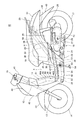
図1は本発明に係る自動二輪車の左側面図である。自動二輪車10(鞍乗型車両)は、車体フレーム11と、車体フレーム11の前部のヘッドパイプ12に取付けられた左右一対のフロントフォーク13と、フロントフォーク13の下端に取付けられた前輪14と、フロントフォーク13の上部に連結されたハンドル15と、車体フレーム11の前後の中間部に上下にスイング可能に取付けられたパワーユニット16と、パワーユニット16の後部に取付けられた後輪17と、パワーユニット16の後端部と車体フレーム11の後部との間に掛け渡されたリヤクッションユニット18と、車体フレーム11の後部に取付けられた収納ボックス19と、収納ボックス19の上方に配置され運転者が着座するシート20と、燃料タンク24と、車体フレーム11を覆う樹脂製のボディカバー44とを、主要構成としたスクータ型の鞍乗型車両である。
FIG. 1 is a left side view of a motorcycle according to the present invention. The motorcycle 10 (saddle-type vehicle) includes a
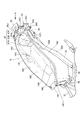
図2は、車体フレーム11の斜視図である。車体フレーム11は、ヘッドパイプ12と、ヘッドパイプ12の後面から後下方に延びる1本のメインフレーム30と、メインフレーム30の下部に接続されて車幅方向に延びるフロントクロスフレーム31と、フロントクロスフレーム31の左右端から後方に延びる左右一対のロアフレーム32,32と、ロアフレーム32,32の後部に設けられ、左右のロアフレーム32,32を連結するセンタークロスパイプ34と、センタークロスパイプ34から後上がりに車両後部まで延びるリヤフレーム33,33と、を備えて構成されている。
前輪14及びフロントフォーク13を含む操向系は、ヘッドパイプ12に軸支されるステアリングシャフト(不図示)によって回動自在に軸支される。
FIG. 2 is a perspective view of the
The steering system including the
リヤフレーム33,33の後端には、左右のリヤフレーム33,33を連結するリヤクロスフレーム35が設けられ、リヤフレーム33,33の前端よりの後傾部には、左右のリヤフレーム33,33を連結するクロスパイプ36が設けられている。
左右のロアフレーム32,32の上方には、メインフレーム30と左右のリヤフレーム33,33とを連結する左右一対のフロアフレーム37,37が設けられている。フロアフレーム37,37の後部は、リヤフレーム33,33から車幅方向に張り出すピリオンステップブラケット38,38に連結されている。ピリオンステップブラケット38,38には、シート20の後部に着座する乗員が足を載せるピリオンステップ39(図1)が取付けられる。
左側のロアフレーム32には、サイドスタンドブラケット53が設けられ、サイドスタンドブラケット53には、折りたたみ可能なサイドスタンド54(図1)が取付けられる。また、リヤフレーム33,33の前部の後面には、パワーユニット16が連結されるパワーユニット連結部55が設けられている。
A
Above the left and right
A
パワーユニット16は、図1に示すように、前部のエンジン21と、このエンジン21の後部に連なって後輪17を駆動する動力伝達機構22とを有し、その前部に連結されたリンク23を介してパワーユニット連結部55に揺動可能に連結される。パワーユニット16は、リヤフレーム33の下方を後方に延びて後輪17を軸支しており、後輪17を支持するスイングアームとしての機能も備えたユニットスイングエンジンである。
パワーユニット16の上部には、取り込んだ空気を浄化してエンジン21に供給するエアクリーナーボックス25が連結されている。エンジン21から延びるマフラー28は、後輪17の右側方に配置されている。
また、パワーユニット16の左側面には、エンジン21をキックで始動させるキックペダル26が設けられ、パワーユニット16の下部には、自動二輪車10を直立状態に支持するメインスタンド27が取付けられている。
As shown in FIG. 1, the
Connected to the upper portion of the
A
ボディカバー44は、ヘッドパイプ12及びメインフレーム30の前方を覆うフロントカバー45と、フロントカバー45に連結され、ヘッドパイプ12及びメインフレーム30の後方を覆うレッグシールド46と、レッグシールド46の下部に連続し、左右のフロアフレーム37,37を上方から覆うステップフロア47と、フロントカバー45の下部に連なってステップフロア47を下方から覆うフロアアンダーカバー48と、収納ボックス19の前部を覆うシート下カバー49と、リヤフレーム33,33及び収納ボックス19を側方から覆う左右一対のリヤカバー50と、シート20の下方で車両の後面を覆うテールカバー51とを備えている。
The body cover 44 is connected to the
フロアアンダーカバー48の左右の側面部は、ロアフレーム32,32及びフロアフレーム37,37を外側方から覆っている。
ハンドル15の周囲はハンドルカバー41によって覆われている。フロントフォーク13には、前輪14の上方を覆うフロントフェンダー42が設けられ、リヤカバー50の下方には、後輪17の上方を覆うリヤフェンダー43が設けられている。収納ボックス19は開閉自在なシート20によって開閉され、シート20の後部には、グラブバー29が設けられている。エンジン21の燃料を貯留するエネルギー貯蔵箱としての燃料タンク24は、ステップフロア47の下方に配置されている。
The left and right side portions of the floor under
The periphery of the
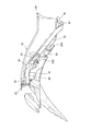
図3は、左右のリヤフレーム33の間に収納ボックス19を取付けた状態を示す斜視図である。収納ボックス19は、リヤフレーム33に沿って延設され、上面に大きな上面開口(上方開口部)19Aが設けられたケース体であり、例えば前部にヘルメットH(図1)を収容し、後部に荷物などを収容するものである。
収納ボックス19の後端部には、メンテナンスリッド67が設けられている。メンテナンスリッド67の内側には、後述の図8に示すように、メンテナンス用の空間65が形成されており、メンテナンス用の空間65には後述するバッテリ70の電極72、及びヒューズ75が露出している。
FIG. 3 is a perspective view showing a state in which the
A
左右のリヤフレーム33は、図1に示すように、側面視では、センタークロスパイプ34からクロスパイプ36近傍まで急激に後上がりに傾斜して延び、クロスパイプ36付近で屈曲して緩やかな傾斜角度で延び、再び屈曲して略水平方向に延びて後端に至る。左右のリヤフレーム33の間隔は、図2に示すように、センタークロスパイプ34からクロスパイプ36を経て第1屈曲部33Aに至るまでほぼ均一であり、第1屈曲部33Aで車幅方向内側へ屈曲し、第2屈曲部33Bまで徐々に幅狭となり、第2屈曲部33Bから後端まで幅狭のまま、間隔が均一となる。
収納ボックス19は、図3に示すように、リヤフレーム33の前部の、クロスパイプ36近傍から、リヤフレーム33の後部の、リヤクロスフレーム35付近までの部分に、左右のリヤフレーム33間に嵌り込んで配置されている。すなわち、収納ボックス19は、図1および図9に示すように、側面視でリヤフレーム33と重なっている。収納ボックス19の前部では、底部19B近傍をリヤフレーム33が通り、後端部では上面開口19Aの近傍をリヤフレーム33が通っている。
As shown in FIG. 1, the left and right rear frames 33 extend from the
As shown in FIG. 3, the
収納ボックス19は、以下のように固定されている。
すなわち、底部19Bの前端には、図4に示すように左右一対の取付孔19Nが設けられており、取付孔19Nを貫通する取付けねじ(不図示)が、クロスパイプ36に設けられた左右一対の支持ステイ56(図3)に締め込まれている。また、側壁部19Cに形成された段部19Dにも、取付孔19Oが設けられ、この取付孔19Oを貫通する取付けねじ(不図示)が、リヤフレーム33の上面に締め込まれている。また、上面開口19Aの後端には、リヤクロスフレーム35の上面にオーバーラップするように、支持フランジ19Eが一体に延設されており、この支持フランジ19Eがリヤクロスフレーム35の取付部35Aの上面に支持されている。
The
That is, as shown in FIG. 4, a pair of left and right mounting
収納ボックス19の上面前端には、図3に示すように、乗員のシート20(図1参照)を開閉自在に取付けるためのシート取付け部19Fが設けられ、シート取付け部19Fの孔19F−1に嵌る支持軸(不図示)により、シート20の前縁部が開閉自在にヒンジ連結(不図示)されている。収納ボックス19の上面開口19Aがシート20により塞がれることで、図1に示すように、収納ボックス19の内側に、ヘルメットHや、荷物、及び電装部品などの収容空間が形成される。
収納ボックス19は、図1および図9(A)に示すように、側面視では、底部19Bの前部が、ヘルメットHを収容できるように、シート20の上面に対して低い位置に略水平に形成され、後部はエアクリーナなどの部品を配置するスペースを確保するために後ろ上がりに傾斜して形成されている。
As shown in FIG. 3, a
As shown in FIGS. 1 and 9A, the
また、収納ボックス19の底部19Bは、図4に示すように、上面視では、前部がヘルメットの形状に沿うように略楕円形状に形成され、後部がリヤフレーム33の間に嵌り込むように略矩形に形成されている。
底部19Bの前部には、図4、図5に示すように、上側に凹む凹部19Gが設けられ、吸気系部品の配置スペースが確保されている。また、底部19Bの前部には水抜き孔19Hが設けられている。底部19Bの後部には、メンテナンスリッド67を位置決めするための係止部19Iが設けられている。
収納ボックス19の側壁部19Cには、幅狭となる第1屈曲部33Aより後方の部分において、リヤフレーム33の上面に沿うように段部19Dが形成され、この段部19Dより上方の部分が、リヤフレーム33の外側面に沿うように幅広に形成されており、収納容量の増大が図られている。
Further, as shown in FIG. 4, the
As shown in FIGS. 4 and 5, a
A
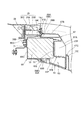
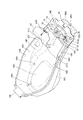
図6は、図4におけるVI−VI断面図である。
メンテナンスリッド67の内側には、上述したように、メンテナンス用の空間65が延在し、この空間65には、サブボックス(電装部品収納部)69が連設されている。すなわち、収納ボックス19の後壁19Jには、後壁開口19Kが開口し、後壁開口19Kには、リヤクロスフレーム35の下方に延出するようにサブボックス69が連設され、サブボックス69は収納ボックス19の後壁開口19Kに接合されている。
サブボックス69は箱状のケース体であり、バッテリ70を収容し、このバッテリ70は、サブボックス69の内側に収容された後に、メンテナンスリッド67で位置決めされている。サブボックス69は、図5、図7に示すように、左右のリヤフレーム33の後端部間に嵌り込み、リヤクロスフレーム35の上方連結板35Bの下方かつリヤクロスフレーム35の後方連結板35Cの前方に位置している。これにより、リヤクロスフレーム35下方のデッドスペースを有効利用できる。サブボックス69は、側面視でリヤフレーム33に重なっている。これにより、リヤフレーム33でバッテリ70を保護することができる。
6 is a sectional view taken along line VI-VI in FIG.
As described above, the
The sub-box 69 is a box-shaped case body, and the
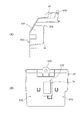
図7は、図3の矢印A方向からの矢視図である。サブボックス69の後壁69Cには突起69Dが設けられている。また、リヤクロスフレーム35の後方連結板35Cには支持孔35Dが開口し、支持孔35Dには弾性部材からなるラバー71が配置されている。そして、サブボックス69の突起69Dはラバー71を介してリヤクロスフレーム35の支持孔35Dに差し込んで固定され、これにより、サブボックス69が支持されている。これによれば、突起69Dが支持孔35Dに支持されるため、バッテリ70の自重によりサブボックス69が押下されても、サブボックス69が強固にリヤクロスフレーム35に支持される。
FIG. 7 is an arrow view from the direction of arrow A in FIG. A
収納ボックス19およびサブボックス69は、ともに樹脂で形成されている。サブボックス69の前壁69Aには、図6に示すように、接合フランジ69Eが設けられ、収納ボックス19の後壁19Jの後壁開口19K内に前方からサブボックス69を挿入して、接合フランジ69Eを収納ボックス19の後壁19Jに押し当てた状態で、図9Bに示すように、収納ボックス19の後壁19Jに、サブボックス69の前壁69Aを溶着または接着により接合されることで、収納ボックス19に一体化されている。
本実施形態では、収納ボックス19およびサブボックス69は、溶着または接着により一体化された状態で、前方からリヤフレーム33に嵌め込まれて取付けられる。これによれば、取付け時の取り扱いが容易となり、取付け作業が簡単になる。
The
In the present embodiment, the
メンテナンスリッド67は、図6に示すように、メンテナンス用の空間65の開口部を塞ぐものであり、前壁部67Aと上壁部67Bとを備える。
メンテナンスリッド67の前壁部67Aの下部前方には係止片67Cが形成されており、この係止片67Cが、収納ボックス19の底部19Bに設けられた係止部19Iに係止されることでメンテナンスリッド67が位置決めされている。メンテナンスリッド67の上壁部67Bの後端には、取付フランジ67Dが設けられており、この取付フランジ67Dを、収納ボックス19の後壁19Jにねじ止めすることでメンテナンスリッド67が固定されている。
As shown in FIG. 6, the
A
メンテナンスリッド67の前壁部67Aの後面には、後方(バッテリ70側)へ膨出する膨出部67Eが形成されている。膨出部67Eには、弾性材料からなるバッテリクッション74が設けられ、このバッテリクッション74がバッテリ70に当接している。すなわち、メンテナンスリッド67の膨出部67Eはバッテリ70に当接して、バッテリ70を抑えている。これにより、バッテリ70が動くことを防止でき、耐振動性を向上できる。
また、前壁部67Aの前面には、上記膨出部67Eに対応する位置に後方(バッテリ70側)に凹んだ凹部67Fが設けられており、図3に示すように、収納ボックス19の上面開口19A内にメンテナンスリッドの凹部67Fが露出している。これにより、メンテナンスリッド67の取付け作業や取り外し作業を行う際に、メンテナンスリッド67に手をかけやすくなり、メンテナンスリッド67の取付けまたは取り外し作業が容易となる。
また、図10(A)、図10(B)に示すように、上記膨出部67Eの左右両側には、膨出部67Eと比較して前方へ張り出すヒューズ収納部67Gが設けられている。これにより膨出部67Eの側方のデッドスペースを利用してヒューズ75(図8参照)をコンパクトに収納できる。
On the rear surface of the
Further, the front surface of the
Further, as shown in FIGS. 10A and 10B,
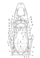
図8は、収納ボックス19において、メンテナンスリッド67を取り外した状態を示す図である。
収納ボックス19の係止部19Iの後方には、左右両側にヒューズ75が配置され、このヒューズ75の後方に、バッテリ70が配置されている。
バッテリ70の後部は、収納ボックス19の後壁開口19K(図9参照)に接合されたサブボックス69に収容されている。一方、バッテリ70の前部は収納ボックス19の空間65内に突出しており、前部上面に電極72が設けられている。すなわち、バッテリ70の電極72は、上面開口19Aの上面からの投影面内に入り込んでおり、メンテナンスリッド67を取り外した状態では、バッテリ70の電極72が空間65に位置し、上面視で露出する。バッテリ70の電極72には電線73が接続されており、収納ボックス19の底部19Bに設けられた電線孔19M(図5参照)から外側に延出している。
これにより、メンテナンスリッド67を取り外した状態で、バッテリ70の電極72、及び電極72に接続される電線73が上面視で露出するので、バッテリ70の電極72に電線73を取付けまたは取り外しする際に、作業を上方から行うことができ作業姿勢が楽になるうえ、上方からの光が遮られることがなく明るくなるため、作業性が向上する。
FIG. 8 is a view showing a state in which the
Behind the locking portion 19I of the
The rear part of the
Thus, the
次いで、リヤフレーム33後部の電装部品について説明する。図2に示すように、左右のリヤフレーム33の間隔は、第1屈曲部33Aより後方では、第2屈曲部33Bまで徐々に幅狭となり、第2屈曲部33Bから後端まで幅狭のまま、間隔が均一となる。これにより、リヤフレーム33の第1屈曲部33Aより後方では、リヤフレーム33の外側に部品を配置するスペースが確保されている。そして、図11に示すように、右側のリヤフレーム33の第1屈曲部33Aより後方の部分には、ライティングカットリレー80、スタータリレー81、ECU82、レギュレート/レクチファイヤ83、およびイグニッションコイル84が、後方からこの順番で支持されている。
バッテリ70の電極72に接続された電線73は、複数の電線(不図示)に分岐し、直接またはヒューズ75を経由して、収納ボックス19の底部19Bの後部右側に設けられた電線孔19M(図5参照)から延出し、各電線(不図示)が、ライティングカットリレー80、スタータリレー81、およびレギュレート/レクチファイヤ83に接続される。
本実施形態では、バッテリ70に直接またはヒューズ75を介して接続される電装部品、すなわちスタータリレー81、ライティングカットリレー80、およびレギュレート/レクチファイヤ83が、バッテリ70の近くに配置されているので、配線距離を短くでき電力損失を防止できる。
Next, electrical components at the rear of the
The
In the present embodiment, since the electrical components connected to the
この車両では、リヤフレーム33が収納ボックス19の上面開口19A近傍を通って収納ボックス19の後方に延出している。このときリヤフレーム33の上方にバッテリ70を収納すれば、車両高さが高くなり、リヤフレーム33の後方にバッテリ70を配置すれば、車両長さが長くなる。本実施形態によれば、左右のリヤフレーム33の収納ボックス19より後方の部位を連結するリヤクロスフレーム35の下方に、バッテリ70を収容するサブボックス69を配置したので、リヤクロスフレーム35の下方のデッドスペースを有効に活用して、車両高さを高くすることなく、車両長さを長くすることなく、バッテリ70の収納スペースを確保できる。
In this vehicle, the
この車両では、収納ボックス19の後端部に、リヤクロスフレーム35の下方に延在させたサブボックス69を溶着し、サブボックス69内にバッテリ70を収納している。これによると、バッテリ70の自重によりサブボックス69が押下されるが、本実施形態によれば、サブボックス69の後壁69Cに突起69Dを設け、この突起69Dをリヤクロスフレーム35に設けた支持孔35Dに差し込んで支持しているため、バッテリ70の自重によりサブボックス69が押下されても、サブボックス69をリヤクロスフレーム35で強固に支持できる。
また、本実施形態では、サブボックス69と収納ボックス19を一体化してリヤフレーム33に取付けるので、取付け時の取り扱いが容易となり、取付け作業が簡単になる。
また、本実施形態では、サブボックス69および収納ボックス19は共に樹脂製であり、サブボックス69は収納ボックス19に溶着または接着により取付けられている。材料として軽量な樹脂を用い、接合方法として接合強度の高い溶着または接着を用いるので、サブボックス69および収納ボックス19を軽量化しつつ、サブボックス69を強固に支持することができる。
In this vehicle, a sub-box 69 extending below the
In this embodiment, since the
In the present embodiment, the
また、本実施形態では、バッテリ70はメンテナンスリッド67を開けた状態においてバッテリ70の電極72が上面視にて露出するように配置されている。
メンテナンスリッド67を開けた状態でバッテリ70の電極72が上面視にて露出するので、バッテリ70の電極72に上方からアクセスできるうえ、上方からの光が遮られることがなくバッテリの電極72付近が明るくなるため、電極72に接続される電線73の取付け作業や取り外し作業が容易になる。
また、本実施形態では、メンテナンスリッド67は、バッテリ70側の面に、バッテリ70に当接するように膨出する膨出部67Eを備え、反対側の面には、膨出部67Eに対応する位置に凹部67Fを備えている。膨出部67Eがバッテリ70に当接するので、バッテリ70を膨出部67Eで抑えることができバッテリ70の位置ずれや振動を防止できる。また、凹部67Fが設けられているので、シート20を開放して収納ボックス19の上面開口19Aからアクセスしてメンテナンスリッド67を取り外す際に、メンテナンスリッド67を保持しやすく、作業性が向上する。
In the present embodiment, the
Since the
Further, in the present embodiment, the
また、本実施形態では、メンテナンスリッド67は、膨出部67Eの側方にヒューズ収納部67Gを備えているので、デッドスペースを有効に利用できる。
サブボックス69は、側面視でリヤフレーム33と重なっているので、リヤフレーム33でバッテリ70を保護できる。
バッテリ70が、収納ボックス19の後端下部に位置しているため、収納ボックス19の容量を大きく確保できる。また、収納ボックス19の底部19Bに、バッテリ70を避ける凹凸形状が無いため、収納ボックス19内に荷物を収容しやすい。
Further, in the present embodiment, the
Since the
Since the
10 自動二輪車
11 車体フレーム
19 収納ユニット
20 シート
33 リヤフレーム
35 リヤクロスフレーム
67 メンテナンスリッド
67E 膨出部
67F 凹部
67G ヒューズ収納部
19 収納ボックス(収納ボックス)
19A 上面開口(上方開口部)
69 サブボックス(電装部品収納部)
69B 開口(メンテナンス用開口部)
70 バッテリ
72 電極
DESCRIPTION OF
19A Upper surface opening (upper opening)
69 Subbox (electrical parts storage)
69B opening (maintenance opening)
70
Claims (8)
前記収納ボックス(19)の後部では、リヤフレーム(33)は前記上方開口部(19A)近傍に配置され、前記左右のリヤフレーム(33)の収納ボックス(19)より後方の部位を連結するリヤクロスフレーム(35)を備え、前記電装部品収納部(69)は、前記リヤクロスフレーム(35)の下方に配置され、前記収納ボックス(19)に支持されることを特徴とする鞍乗型車両。 A rear frame (33) disposed at the rear of the vehicle and extending in the front-rear direction, and a pair of left and right rear frames (33) and an upper opening (19A) disposed between the pair of left and right rear frames (33) and opening upward A storage box (19) provided with a seat, a seat (20) for occupant seating that is supported so that the upper opening (19A) can be opened and closed, and a storage box (19). In a straddle-type vehicle provided with an electrical component storage portion (69) provided with a maintenance opening portion (69B) that opens on the side) and a maintenance lid (67) that closes the maintenance opening portion (69B). ,
At the rear part of the storage box (19), a rear frame (33) is arranged in the vicinity of the upper opening (19A), and connects the rear part of the left and right rear frames (33) with respect to the rear part. A straddle-type vehicle comprising a cross frame (35), wherein the electrical component storage section (69) is disposed below the rear cross frame (35) and supported by the storage box (19). .
Priority Applications (3)
| Application Number | Priority Date | Filing Date | Title |
|---|---|---|---|
| JP2011003281A JP5690147B2 (en) | 2011-01-11 | 2011-01-11 | Saddle riding vehicle |
| US13/340,778 US8794687B2 (en) | 2011-01-11 | 2011-12-30 | Saddle type vehicle having an accommodation box |
| CN201210001299.3A CN102582742B (en) | 2011-01-11 | 2012-01-04 | Saddle type vehicle |
Applications Claiming Priority (1)
| Application Number | Priority Date | Filing Date | Title |
|---|---|---|---|
| JP2011003281A JP5690147B2 (en) | 2011-01-11 | 2011-01-11 | Saddle riding vehicle |
Publications (2)
| Publication Number | Publication Date |
|---|---|
| JP2012144131A true JP2012144131A (en) | 2012-08-02 |
| JP5690147B2 JP5690147B2 (en) | 2015-03-25 |
Family
ID=46454691
Family Applications (1)
| Application Number | Title | Priority Date | Filing Date |
|---|---|---|---|
| JP2011003281A Expired - Fee Related JP5690147B2 (en) | 2011-01-11 | 2011-01-11 | Saddle riding vehicle |
Country Status (3)
| Country | Link |
|---|---|
| US (1) | US8794687B2 (en) |
| JP (1) | JP5690147B2 (en) |
| CN (1) | CN102582742B (en) |
Cited By (6)
| Publication number | Priority date | Publication date | Assignee | Title |
|---|---|---|---|---|
| JP2014144756A (en) * | 2013-01-30 | 2014-08-14 | Honda Motor Co Ltd | Battery arrangement structure of saddle-riding type vehicle |
| JP2014184944A (en) * | 2013-02-25 | 2014-10-02 | Honda Motor Co Ltd | Reservoir tank feed water structure of saddle-ride type vehicle |
| JP2014198541A (en) * | 2013-03-29 | 2014-10-23 | 本田技研工業株式会社 | Rear fender support structure of saddle riding type vehicle |
| JP2016037117A (en) * | 2014-08-06 | 2016-03-22 | スズキ株式会社 | Motorcycle storage box mounting structure |
| JP2017507845A (en) * | 2014-03-18 | 2017-03-23 | 本田技研工業株式会社 | Engine control unit mounting structure for motorcycles |
| EP3636524A1 (en) | 2018-10-11 | 2020-04-15 | Yamaha Hatsudoki Kabushiki Kaisha | Straddled vehicle |
Families Citing this family (10)
| Publication number | Priority date | Publication date | Assignee | Title |
|---|---|---|---|---|
| JP5913030B2 (en) * | 2012-03-22 | 2016-04-27 | 本田技研工業株式会社 | Storage structure for saddle-ride type vehicles |
| JP6018861B2 (en) * | 2012-09-20 | 2016-11-02 | 本田技研工業株式会社 | Saddle riding vehicle |
| US9724989B2 (en) * | 2014-12-30 | 2017-08-08 | Yamaha Hatsudoki Kabushiki Kaisha | Vehicle |
| TWI659874B (en) * | 2015-09-18 | 2019-05-21 | 光陽工業股份有限公司 | Battery accommodation mechanism |
| CN106627886B (en) * | 2015-10-28 | 2020-09-29 | 光阳工业股份有限公司 | Motorcycle starter relay configuration structure |
| JP6487886B2 (en) * | 2016-09-23 | 2019-03-20 | 本田技研工業株式会社 | Storage box structure for saddle-ride type vehicles |
| JP6915072B2 (en) * | 2017-09-29 | 2021-08-04 | 本田技研工業株式会社 | Battery layout and saddle-mounted vehicle |
| WO2019065390A1 (en) * | 2017-09-29 | 2019-04-04 | 本田技研工業株式会社 | Hybrid vehicle |
| CN110435800B (en) * | 2018-05-03 | 2021-05-28 | 本田技研工业株式会社 | Saddle-type electric vehicle |
| WO2022195606A1 (en) * | 2021-03-15 | 2022-09-22 | Tvs Motor Company Limited | A motor vehicle |
Citations (5)
| Publication number | Priority date | Publication date | Assignee | Title |
|---|---|---|---|---|
| JPH058775A (en) * | 1991-07-02 | 1993-01-19 | Honda Motor Co Ltd | Luggage box for motorcycle |
| JPH0769259A (en) * | 1993-08-31 | 1995-03-14 | Honda Motor Co Ltd | Battery layout structure for motorcycles |
| JPH10324281A (en) * | 1998-04-10 | 1998-12-08 | Honda Motor Co Ltd | Evaporative gas control device for scooter type vehicle |
| JP2002225765A (en) * | 2001-01-30 | 2002-08-14 | Honda Motor Co Ltd | Storage box structure for motorcycle |
| JP2009018813A (en) * | 2001-09-27 | 2009-01-29 | Yamaha Motor Co Ltd | Motorcycle |
Family Cites Families (13)
| Publication number | Priority date | Publication date | Assignee | Title |
|---|---|---|---|---|
| JPS4938851Y2 (en) * | 1971-03-22 | 1974-10-24 | ||
| JPS5950885A (en) * | 1982-09-14 | 1984-03-24 | 本田技研工業株式会社 | Motorcycle |
| JP2891802B2 (en) * | 1991-05-29 | 1999-05-17 | 本田技研工業株式会社 | Battery layout structure for scooter type vehicle |
| JP3345064B2 (en) * | 1992-11-27 | 2002-11-18 | 本田技研工業株式会社 | Scooter type vehicle |
| JPH07134938A (en) * | 1993-11-11 | 1995-05-23 | Honda Motor Co Ltd | Battery coupler with fuse |
| JP4364341B2 (en) * | 1999-03-31 | 2009-11-18 | 本田技研工業株式会社 | Article storage device for motorcycle |
| US6588529B2 (en) * | 2000-07-05 | 2003-07-08 | Yamaha Hatsudoki Kabishuki Kaisha | Body cover and structure for motorcycle |
| JP4014804B2 (en) | 2001-01-10 | 2007-11-28 | 本田技研工業株式会社 | Vehicle inspection device |
| TWI247707B (en) * | 2004-01-20 | 2006-01-21 | Honda Motor Co Ltd | Lock release operator layout structure in vehicle |
| JP4546204B2 (en) * | 2004-09-29 | 2010-09-15 | 本田技研工業株式会社 | Grab rail |
| CN201154741Y (en) | 2007-12-14 | 2008-11-26 | 光阳工业股份有限公司 | Motorcycle rear maintenance port structure |
| CN201276168Y (en) * | 2008-10-07 | 2009-07-22 | 光阳工业股份有限公司 | Jet engine motorcycle |
| JP5913030B2 (en) * | 2012-03-22 | 2016-04-27 | 本田技研工業株式会社 | Storage structure for saddle-ride type vehicles |
-
2011
- 2011-01-11 JP JP2011003281A patent/JP5690147B2/en not_active Expired - Fee Related
- 2011-12-30 US US13/340,778 patent/US8794687B2/en not_active Expired - Fee Related
-
2012
- 2012-01-04 CN CN201210001299.3A patent/CN102582742B/en not_active Expired - Fee Related
Patent Citations (5)
| Publication number | Priority date | Publication date | Assignee | Title |
|---|---|---|---|---|
| JPH058775A (en) * | 1991-07-02 | 1993-01-19 | Honda Motor Co Ltd | Luggage box for motorcycle |
| JPH0769259A (en) * | 1993-08-31 | 1995-03-14 | Honda Motor Co Ltd | Battery layout structure for motorcycles |
| JPH10324281A (en) * | 1998-04-10 | 1998-12-08 | Honda Motor Co Ltd | Evaporative gas control device for scooter type vehicle |
| JP2002225765A (en) * | 2001-01-30 | 2002-08-14 | Honda Motor Co Ltd | Storage box structure for motorcycle |
| JP2009018813A (en) * | 2001-09-27 | 2009-01-29 | Yamaha Motor Co Ltd | Motorcycle |
Cited By (6)
| Publication number | Priority date | Publication date | Assignee | Title |
|---|---|---|---|---|
| JP2014144756A (en) * | 2013-01-30 | 2014-08-14 | Honda Motor Co Ltd | Battery arrangement structure of saddle-riding type vehicle |
| JP2014184944A (en) * | 2013-02-25 | 2014-10-02 | Honda Motor Co Ltd | Reservoir tank feed water structure of saddle-ride type vehicle |
| JP2014198541A (en) * | 2013-03-29 | 2014-10-23 | 本田技研工業株式会社 | Rear fender support structure of saddle riding type vehicle |
| JP2017507845A (en) * | 2014-03-18 | 2017-03-23 | 本田技研工業株式会社 | Engine control unit mounting structure for motorcycles |
| JP2016037117A (en) * | 2014-08-06 | 2016-03-22 | スズキ株式会社 | Motorcycle storage box mounting structure |
| EP3636524A1 (en) | 2018-10-11 | 2020-04-15 | Yamaha Hatsudoki Kabushiki Kaisha | Straddled vehicle |
Also Published As
| Publication number | Publication date |
|---|---|
| JP5690147B2 (en) | 2015-03-25 |
| US8794687B2 (en) | 2014-08-05 |
| CN102582742A (en) | 2012-07-18 |
| CN102582742B (en) | 2014-07-23 |
| US20120175906A1 (en) | 2012-07-12 |
Similar Documents
| Publication | Publication Date | Title |
|---|---|---|
| JP5690147B2 (en) | Saddle riding vehicle | |
| JP4077173B2 (en) | Scooter type vehicle | |
| JP5879173B2 (en) | Electric saddle riding type vehicle | |
| JP5774129B2 (en) | Saddle riding vehicle | |
| JP5694788B2 (en) | Saddle riding vehicle | |
| US8794366B2 (en) | Battery case structure for motorcycle | |
| JP5926653B2 (en) | Storage structure of saddle-ride type vehicle | |
| JP2002225765A (en) | Storage box structure for motorcycle | |
| JP5581674B2 (en) | Motorcycle seat support structure | |
| JP2016193647A (en) | Saddle-riding type vehicle | |
| JP5548730B2 (en) | Scooter type vehicle | |
| JP4112818B2 (en) | Scooter type vehicle | |
| JP5694789B2 (en) | Fuel tank support structure for saddle-ride type vehicles | |
| JPWO2018159014A1 (en) | Meter mounting structure for saddle-ride type vehicles | |
| JP5578999B2 (en) | Saddle riding vehicle | |
| JP2022065831A (en) | Vehicle body structure of saddle-riding type vehicle | |
| WO2010035460A1 (en) | Fastening structure for vehicle front cover | |
| WO2019193797A1 (en) | Saddle-ride type vehicle | |
| JP6139592B2 (en) | Saddle riding | |
| JP4247854B2 (en) | Motorcycle storage box | |
| JP7369748B2 (en) | saddle type vehicle | |
| JP6184437B2 (en) | Motorcycle | |
| JP5802038B2 (en) | Saddle riding | |
| CN220948350U (en) | Saddle-type vehicle | |
| JP7355856B2 (en) | Control device layout structure |
Legal Events
| Date | Code | Title | Description |
|---|---|---|---|
| A621 | Written request for application examination |
Free format text: JAPANESE INTERMEDIATE CODE: A621 Effective date: 20131127 |
|
| A977 | Report on retrieval |
Free format text: JAPANESE INTERMEDIATE CODE: A971007 Effective date: 20140620 |
|
| A131 | Notification of reasons for refusal |
Free format text: JAPANESE INTERMEDIATE CODE: A131 Effective date: 20140701 |
|
| A521 | Request for written amendment filed |
Free format text: JAPANESE INTERMEDIATE CODE: A523 Effective date: 20140828 |
|
| TRDD | Decision of grant or rejection written | ||
| A01 | Written decision to grant a patent or to grant a registration (utility model) |
Free format text: JAPANESE INTERMEDIATE CODE: A01 Effective date: 20150127 |
|
| A61 | First payment of annual fees (during grant procedure) |
Free format text: JAPANESE INTERMEDIATE CODE: A61 Effective date: 20150130 |
|
| R150 | Certificate of patent or registration of utility model |
Ref document number: 5690147 Country of ref document: JP Free format text: JAPANESE INTERMEDIATE CODE: R150 |
|
| LAPS | Cancellation because of no payment of annual fees |