JP2011136826A - Passenger conveyor - Google Patents

Passenger conveyor Download PDF

Info

Publication number
JP2011136826A
JP2011136826A JP2009299214A JP2009299214A JP2011136826A JP 2011136826 A JP2011136826 A JP 2011136826A JP 2009299214 A JP2009299214 A JP 2009299214A JP 2009299214 A JP2009299214 A JP 2009299214A JP 2011136826 A JP2011136826 A JP 2011136826A
Authority
JP
Japan
Prior art keywords
conveyor
belt
speed
width direction
conveyors
Prior art date
Legal status (The legal status is an assumption and is not a legal conclusion. Google has not performed a legal analysis and makes no representation as to the accuracy of the status listed.)
Pending
Application number
JP2009299214A
Other languages
Japanese (ja)
Inventor
Yoshinobu Ishikawa
佳延 石川
Shin Murakami
伸 村上
Takayuki Kikuchi
孝幸 菊池
Yasuaki Takeda
泰明 武田
Kenji Fujiwara
憲治 藤原
Atsushi Maeda
敦司 前田
Kenichi Okuyama
健一 奥山
Toshinori Iwai
俊憲 岩井
Tomoya Ishizuka
智也 石塚
Current Assignee (The listed assignees may be inaccurate. Google has not performed a legal analysis and makes no representation or warranty as to the accuracy of the list.)
Toshiba Elevator and Building Systems Corp
Original Assignee
Toshiba Elevator Co Ltd
Priority date (The priority date is an assumption and is not a legal conclusion. Google has not performed a legal analysis and makes no representation as to the accuracy of the date listed.)
Filing date
Publication date
Application filed by Toshiba Elevator Co Ltd filed Critical Toshiba Elevator Co Ltd
Priority to JP2009299214A priority Critical patent/JP2011136826A/en
Priority to CN201010612054.5A priority patent/CN102126664B/en
Publication of JP2011136826A publication Critical patent/JP2011136826A/en
Pending legal-status Critical Current

Links

Images

Landscapes

  • Escalators And Moving Walkways (AREA)

Abstract

<P>PROBLEM TO BE SOLVED: To provide a passenger conveyor capable of enhancing transport efficiency of passengers, by increasing a moving speed, while securing safety to the passengers in operation. <P>SOLUTION: The passenger conveyor includes a plurality of conveyors 12a, 12b, 12c, 12d, 12e, 12f and 12g having a plurality of areas different in the moving speed, and the one conveyor is juxtaposed so that a part in the moving direction M overlaps in the width direction W with the other one or two conveyors, and the conveyor adjacent in the width direction W is characterized by setting an overlapping area in the width direction W at the same moving speed. <P>COPYRIGHT: (C)2011,JPO&INPIT

Description

本発明は、乗客を搭乗させて移送する「動く歩道」として利用される乗客コンベアに関する。   The present invention relates to a passenger conveyor used as a “moving sidewalk” for carrying and transporting passengers.

動く歩道として利用される乗客コンベアは、無端環状のベルトを備えている。無端環状のベルトは、乗口から降口までの間に複数設置されたガイドローラによって支持され、駆動部によって循環される。従来の乗客コンベアは、ベルトの折返し部に配置されるプーリでベルトを駆動する構成を有している。駆動部は、乗口付近または降口付近に設けられているものが多い。   A passenger conveyor used as a moving sidewalk includes an endless annular belt. The endless annular belt is supported by a plurality of guide rollers installed between the entrance and the exit, and is circulated by the drive unit. A conventional passenger conveyor has a configuration in which a belt is driven by a pulley disposed at a folded portion of the belt. Many drive units are provided near the entrance or near the exit.

乗客コンベアは、搭乗中の支えとして乗客が掴むために用意された手摺ベルトを有する。手摺ベルトは、無端リングであり、欄干に巻き掛けられている。手摺ベルトは、乗口から降口まで欄干の上に沿って移動して降口から乗口までコンベア装置内を通って戻されるように、循環する。手摺ベルトは、コンベア装置内に設けられた手摺駆動機構によってベルトと同じ速度で駆動される。一般的な手摺駆動機構は、手摺ベルトを駆動ローラと加圧ローラの間に挟み、摩擦力によって手摺ベルトを把持し駆動するものが知られている。   The passenger conveyor has a handrail belt prepared for a passenger to hold as a support during boarding. The handrail belt is an endless ring and is wound around the balustrade. The handrail belt circulates so that it moves along the railing from the entrance to the exit and is returned through the conveyor device from the exit to the entrance. The handrail belt is driven at the same speed as the belt by a handrail drive mechanism provided in the conveyor device. As a general handrail drive mechanism, there is known a mechanism in which a handrail belt is sandwiched between a driving roller and a pressure roller, and the handrail belt is gripped and driven by a frictional force.

近年、乗客の輸送効率を高めるために、乗口付近および降口付近におけるベルトの速度が従来程度であるのに対して中間部におけるベルトの速度が速い中間加速型のベルト式乗客コンベアも散見される。   In recent years, in order to improve passenger transportation efficiency, belt acceleration passenger belts of intermediate acceleration type where the belt speed in the vicinity of the entrance and exit is about the same as the conventional speed but the belt speed in the middle part is fast have been seen. The

例えば、下記特許文献1に記載された「輸送装置」は、移動速度が遅い低速移送部と移動速度の速い高速移送部を有している。この輸送装置は、低速移送部から高速移送部へ、また、高速移送部から低速移送部へ乗客を乗り移らせることによって、中間加速型を実現している。   For example, a “transport device” described in Patent Document 1 below includes a low-speed transfer unit having a low moving speed and a high-speed transfer unit having a high moving speed. This transport device realizes an intermediate acceleration type by transferring passengers from a low-speed transfer unit to a high-speed transfer unit and from the high-speed transfer unit to the low-speed transfer unit.

また、下記特許文献2に記載された「動く歩道」は、移動速度が異なる複数のベルトを直列に配置している。伸縮可能な多数の伸縮パレットがこれらベルトの全体に亘って巻き掛けられている。伸縮パレットは、ベルトで駆動されて循環移動する。この「動く歩道」は、各ベルトの速度に応じて伸縮パレットを伸縮させることにより、中間加速型を実現している。   Moreover, the "moving sidewalk" described in the following Patent Document 2 has a plurality of belts having different moving speeds arranged in series. A large number of stretchable pallets that can be stretched are wound around these belts. The telescopic pallet is circulated and driven by a belt. This “moving sidewalk” realizes an intermediate acceleration type by expanding and contracting the telescopic pallet according to the speed of each belt.

しかしながら、下記特許文献1に記載された「輸送装置」において、移動速度の異なる移送部の間にできる乗り移り部における速度変化は、不連続である。このため乗り移り部において乗客がよろけたり転んだりすることもあり、乗客の安全上好ましくない。しかも、低速移送部と高速移送部との移動速度の比率(加減速比率)を大きくすればするほど、上記した不連続部分において乗客がよろけたり転びやすくなることから、加減速比率を大きく設定して高速移送部の高速化することができず、乗客の輸送効率化に限界がある。   However, in the “transport device” described in Patent Document 1 below, the change in speed at the transfer portion between the transfer portions having different moving speeds is discontinuous. For this reason, passengers may stagger or roll at the transfer section, which is not preferable for passenger safety. In addition, the greater the ratio of the moving speed (acceleration / deceleration ratio) between the low-speed transfer unit and the high-speed transfer unit, the more easily the passengers will stagger and roll at the above-mentioned discontinuous part. Therefore, the speed of the high-speed transfer section cannot be increased, and there is a limit to the efficiency of passenger transportation.

また、下記特許文献2に記載された「動く歩道」において、伸縮パレットが伸びると、機械的な隙間が伸縮パレット上にできる。その隙間に小石などの異物が挟まると、伸縮パレットが物理的に縮まらなくなる不具合が生じる可能性がある。移動速度が減速されないだけでなく、折返し部において伸縮パレットを反転できなくなるため、乗客の安全上好ましくない。   Further, in the “moving sidewalk” described in Patent Document 2 below, when the telescopic pallet is extended, a mechanical gap is formed on the telescopic pallet. If foreign objects such as pebbles get caught in the gap, there is a possibility that the expansion / contraction pallet cannot be physically contracted. Not only is the moving speed not decelerated, but the telescopic pallet cannot be reversed at the turn-up portion, which is undesirable for passenger safety.

特許第3308298号公報Japanese Patent No. 3308298 特開平7−232885号公報Japanese Unexamined Patent Publication No. 7-232828

本発明は上記問題を考慮してなされたものであり、運行中における乗客に対する安全性が確保しつつ、移動速度を高速化して乗客の輸送効率を高めることができる乗客コンベアを提供することを目的とする。   The present invention has been made in consideration of the above problems, and an object of the present invention is to provide a passenger conveyor that can increase the speed of movement and increase the transportation efficiency of passengers while ensuring safety for passengers during operation. And

本発明に係る乗客コンベアは、移動速度の異なる複数の領域を有するコンベアを複数備え、1のコンベアは、他の1又は2のコンベアに対して移動方向の一部が幅方向に重なり合うように並べて配置され、幅方向に隣り合うコンベアは、幅方向に重なり合う領域が同じ移動速度に設定されていることを特徴とする。   The passenger conveyor according to the present invention includes a plurality of conveyors having a plurality of regions having different moving speeds, and one conveyor is arranged so that a part of the moving direction overlaps with the other one or two conveyors in the width direction. The conveyors arranged and adjacent in the width direction are characterized in that the overlapping regions in the width direction are set to the same moving speed.

本発明に係る乗客コンベアでは、上記構成により、運行中における乗客に対する安全性が確保しつつ、移動速度を高速化して乗客の輸送効率を高めることができる。   In the passenger conveyor according to the present invention, with the above-described configuration, the transportation speed of the passenger can be increased by increasing the moving speed while ensuring the safety for the passenger during the operation.

本発明の第1実施形態に係る乗客コンベアを概略的に示す平面図である。It is a top view showing roughly a passenger conveyor concerning a 1st embodiment of the present invention. 図1に示す乗客コンベアの要部を概略的に示す斜視図である。It is a perspective view which shows roughly the principal part of the passenger conveyor shown in FIG. 図1に示す乗客コンベアの要部を概略的に示す平面図である。It is a top view which shows roughly the principal part of the passenger conveyor shown in FIG. 図1に示す乗客コンベアを構成するコンベアの断面図である。It is sectional drawing of the conveyor which comprises the passenger conveyor shown in FIG. 図4に示すコンベアの駆動機構の斜視図である。It is a perspective view of the drive mechanism of the conveyor shown in FIG. 図4に示すコンベアにおいて駆動ベルトから搭乗ベルトへ動力を伝達する機構、および速度変更手段に係る構造部を一部破断した斜視図である。FIG. 5 is a perspective view in which a mechanism for transmitting power from a driving belt to a boarding belt and a structure portion related to speed changing means in the conveyor shown in FIG. 4 are partially broken. 本発明の変更例に係る乗客コンベアを概略的に示す平面図である。It is a top view which shows roughly the passenger conveyor which concerns on the example of a change of this invention.

(第1実施形態)
以下、本発明の第1実施形態について、図面を参照して説明する。
(First embodiment)
Hereinafter, a first embodiment of the present invention will be described with reference to the drawings.

本実施形態における乗客コンベア1は、図1〜図3に示すように、複数台のベルト式のコンベアが幅方向Wに重なり合うように並べて配置されてなり、乗り口13が設けられた加速用コンベア群12と、降り口15が設けられた減速用コンベア群14と、加速用コンベア群12および減速用コンベア群14のそれぞれの終端部に重なり合うように並べて配置された主コンベア16と、幅方向Wに所定間隔をあけて立設された一対の案内壁20とを備える。   As shown in FIGS. 1 to 3, the passenger conveyor 1 in the present embodiment is an acceleration conveyor in which a plurality of belt-type conveyors are arranged side by side so as to overlap in the width direction W, and the entrance 13 is provided. A group 12, a deceleration conveyor group 14 provided with an exit 15, a main conveyor 16 arranged side by side so as to overlap each terminal portion of the acceleration conveyor group 12 and the deceleration conveyor group 14, and a width direction W And a pair of guide walls 20 that are erected at a predetermined interval.

加速用コンベア群12は、複数台(例えば、本実施形態では7台)のコンベア12a,12b,12c,12d,12e,12f,12gを備え、コンベア12aが移動方向Mの後端部に配置され、その前方にコンベア12b、コンベア12c、コンベア12d、コンベア12e、コンベア12fが移動方向Mの一部を幅方向Wに重ねて順次配置されており、移動方向Mの前端部にコンベア12gが配置されている。   The acceleration conveyor group 12 includes a plurality of conveyors 12a, 12b, 12c, 12d, 12e, 12f, and 12g (for example, seven in this embodiment), and the conveyor 12a is disposed at the rear end of the moving direction M. The conveyor 12b, the conveyor 12c, the conveyor 12d, the conveyor 12e, and the conveyor 12f are sequentially arranged in such a manner that a part of the moving direction M is overlapped in the width direction W, and the conveyor 12g is arranged at the front end in the moving direction M. ing.

加速用コンベア群12を構成する個々のコンベア12a,・・・12gは、乗客を搭乗させて移送するベルトを備えるベルト式のコンベアであって、移動方向Mの後部領域より前部領域において乗客を搭乗させる搭乗ベルトの移動速度が高速に設定された加減速型のコンベアから構成されている。なお、個々のコンベア12a,・・・12gは、搭乗ベルトの移動速度が異なるのみで、各コンベアの構造は同一であるため、ここでは、コンベア12aの構成について説明し、他のコンベア12b,・・・12gの構成の説明を省略する。   Each of the conveyors 12a,..., 12g constituting the acceleration conveyor group 12 is a belt type conveyor having a belt on which passengers are boarded and transported, and the passengers are moved in the front region from the rear region in the moving direction M. It is comprised from the acceleration / deceleration type conveyor by which the moving speed of the boarding belt to board is set to high speed. The individual conveyors 12a,... 12g differ only in the moving speed of the boarding belt, and the structure of each conveyor is the same. Therefore, here, the configuration of the conveyor 12a will be described, and the other conveyors 12b,. -Description of the configuration of 12g is omitted.

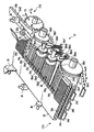
図4〜図6に示すように、コンベア12aが備えるベルトは、主枠32内に配設された駆動系によって循環されるもので、搭乗ベルト33と駆動ベルト34とで二重に構成される。   As shown in FIGS. 4 to 6, the belt provided in the conveyor 12 a is circulated by a drive system disposed in the main frame 32, and is configured by a boarding belt 33 and a drive belt 34. .

搭乗ベルト33は、主枠32内に設けられる所定の循環経路(第1の循環経路)に沿って循環する。駆動ベルト34は、第1の循環経路の内側に設けられる第2の循環経路に沿って循環移動する。駆動ベルト34(34a,34b)は、搭乗ベルト33の内周面に接触することによって、搭乗ベルト33を循環させるための駆動力を搭乗ベルト33に伝達する。また、コンベア12aは、駆動ベルト34(34a,34b)を駆動する駆動機構35(35a,35b)を備えている。   The boarding belt 33 circulates along a predetermined circulation path (first circulation path) provided in the main frame 32. The drive belt 34 circulates and moves along a second circulation path provided inside the first circulation path. The driving belt 34 (34a, 34b) transmits a driving force for circulating the riding belt 33 to the riding belt 33 by contacting the inner peripheral surface of the riding belt 33. Moreover, the conveyor 12a is provided with the drive mechanism 35 (35a, 35b) which drives the drive belt 34 (34a, 34b).

本実施形態において、駆動ベルト34の案内手段6は、ガイドローラなどで構成されている。案内手段6は、主枠32の内部に配置されている。案内手段6は、駆動ベルト4に適当な張力を付与するテンショナを含んでいる。   In this embodiment, the guide means 6 of the drive belt 34 is constituted by a guide roller or the like. The guide means 6 is disposed inside the main frame 32. The guide means 6 includes a tensioner that applies an appropriate tension to the drive belt 4.

駆動ベルト34は、搬送方向となる主枠32の長手方向に沿って直列に並ぶように2本設けられる。これに対して、搭乗ベルト33は、乗客コンベアの全長に亘って循環する連続する1本のベルトで構成される。   Two drive belts 34 are provided so as to be arranged in series along the longitudinal direction of the main frame 32 serving as the transport direction. On the other hand, the boarding belt 33 is composed of one continuous belt that circulates over the entire length of the passenger conveyor.

各駆動ベルト34a,34bは、移動方向Mの前側または後側となるコンベア12aの後部領域12a−1または前部領域12a−2に配置されており、直径の大きい折返しローラ8と直径の小さい折返しローラ4fとの間に掛け渡されている。駆動ベルト34は、搭乗ベルト33の循環経路のうちの乗客が乗る部分の範囲内で、搭乗ベルト33と接触するように構成され、搭乗ベルト33へ駆動力を伝達する。なお、搭乗ベルト33の復路部分で駆動ベルト34が搭乗ベルト33と近接している区間においても、駆動ベルト34から搭乗ベルト33へ駆動力を伝達してもよい。   Each drive belt 34a, 34b is disposed in the rear region 12a-1 or the front region 12a-2 of the conveyor 12a on the front side or the rear side in the moving direction M, and has a large diameter folding roller 8 and a small diameter folding roller. It is stretched between the rollers 4f. The drive belt 34 is configured to come into contact with the boarding belt 33 within a range of a portion of the circulation path of the boarding belt 33 where the passenger rides, and transmits the driving force to the boarding belt 33. The driving force may be transmitted from the driving belt 34 to the boarding belt 33 even in a section where the driving belt 34 is close to the boarding belt 33 in the return path portion of the boarding belt 33.

次に、図4〜図6を参照して、後部領域12a−1に配置された第1の駆動ベルト34aを循環移動させるための第1の駆動機構35aおよび、前部領域12a−2に配置された第2の駆動ベルト34bを循環移動させるための第2の駆動機構35bについて説明する。なお、第2の駆動ベルト34bの構造は、第1の駆動ベルト34aの構造と同一であり、したがって、第2の駆動機構35bも、第1の駆動機構35aと同一である。   Next, referring to FIG. 4 to FIG. 6, the first drive mechanism 35 a for circulatingly moving the first drive belt 34 a arranged in the rear region 12 a-1 and the front drive region 12 a-2 are arranged. The second drive mechanism 35b for circulating and moving the second drive belt 34b that has been made will be described. The structure of the second drive belt 34b is the same as the structure of the first drive belt 34a. Therefore, the second drive mechanism 35b is also the same as the first drive mechanism 35a.

図4および図5に示すように、第1の駆動機構35aは、駆動プーリ7を有している。この駆動プーリ7は、駆動ベルト34aの折返し部においてその駆動ベルト34aと噛み合うように設けられている。その噛み合い部の実行長さを確保するため、駆動ベルト34aは、案内ローラ8aを用いて駆動プーリ7に案内される。具体的には、図5に示すように、駆動ベルト34aは、搭乗ベルト33の内周面から離れて駆動プーリ7の外周面に沿って迂回し、折返しローラ8によって再び搭乗ベルト33と重ね合わされる。案内ローラ8aの回転軸は、主枠32の適当な部位に回転自在に取り付けられている。   As shown in FIGS. 4 and 5, the first drive mechanism 35 a has a drive pulley 7. The drive pulley 7 is provided so as to mesh with the drive belt 34a at the folded portion of the drive belt 34a. In order to secure the effective length of the meshing portion, the drive belt 34a is guided to the drive pulley 7 using the guide roller 8a. Specifically, as shown in FIG. 5, the drive belt 34 a is separated from the inner peripheral surface of the boarding belt 33 and detours along the outer peripheral surface of the drive pulley 7, and is overlapped with the boarding belt 33 again by the folding roller 8. The The rotation shaft of the guide roller 8a is rotatably attached to an appropriate part of the main frame 32.

駆動プーリ7と同軸にタイミングプーリ9が付設されている。電動機10の駆動軸10aにはタイミングプーリ10bが取り付けられている。そして、タイミングプーリ10bとタイミングプーリ9との間にタイミングベルト11が掛け渡されている。タイミングプーリ9,10bの代わりにスプロケットを用い、タイミングベルト11の代わりにチェーンを掛けても良い。   A timing pulley 9 is provided coaxially with the drive pulley 7. A timing pulley 10 b is attached to the drive shaft 10 a of the electric motor 10. A timing belt 11 is stretched between the timing pulley 10 b and the timing pulley 9. Sprockets may be used instead of the timing pulleys 9 and 10b, and a chain may be hung instead of the timing belt 11.

電動機10がタイミングプーリ10bを駆動すると、それに同期して、駆動プーリ7が回転する。この結果、駆動ベルト34aが駆動され、搭乗ベルト33が循環移動する。搭乗ベルト33および駆動ベルト34aの各折返し部は、折返しローラ8に互に重なり合って巻き掛けられている。   When the electric motor 10 drives the timing pulley 10b, the driving pulley 7 rotates in synchronization therewith. As a result, the drive belt 34a is driven and the boarding belt 33 circulates. The folded portions of the boarding belt 33 and the drive belt 34a are wound around the folding roller 8 so as to overlap each other.

そして、各駆動ベルト34a,34bは、上記のような構成の駆動機構35a,35bによってそれぞれ駆動される。このとき、第1の駆動ベルト34aは、速度Va1で循環され、第2の駆動ベルト34bは、速度Va1より大きい速度Va2で循環される。   And each drive belt 34a, 34b is each driven by the drive mechanism 35a, 35b of the above structures. At this time, the first drive belt 34a is circulated at a speed Va1, and the second drive belt 34b is circulated at a speed Va2 larger than the speed Va1.

第1の駆動ベルト34aと第2の駆動ベルト34bとの間に速度差を設けるために、各駆動機構35a,35bに設けられるローラスプロケットやタイミングプーリの直径などが適宜設定される。   In order to provide a speed difference between the first drive belt 34a and the second drive belt 34b, the diameters of roller sprockets and timing pulleys provided in the drive mechanisms 35a and 35b are appropriately set.

搭乗ベルト33は、少なくとも循環方向に((Va2/Va1)−1)×100%だけ弾性的に伸びる部材が用いられる。第1の駆動ベルト34a、および第2の駆動ベルト34bは、それぞれ速度Va1,Va2で駆動される。これに伴って搭乗ベルト33は、伸びるので、後部領域12a−1において速度Va1で、前部領域12a−2において速度Va2で移動される。   The boarding belt 33 is a member that elastically extends at least ((Va2 / Va1) -1) × 100% in the circulation direction. The first drive belt 34a and the second drive belt 34b are driven at speeds Va1 and Va2, respectively. Accordingly, the boarding belt 33 is extended, and is thus moved at the speed Va1 in the rear area 12a-1 and at the speed Va2 in the front area 12a-2.

上記のように、コンベア12aは、搭乗ベルト33の伸縮によって後部領域12a−1と前部領域12a−2との速度を変化させるものであり、後部領域12a−1の移動速度Va1と前部領域12a−2の移動速度Va2との速度変化率は、搭乗ベルト33が弾性的に伸縮する伸縮率以下に設定される。本実施形態では、例えば、搭乗ベルト33の伸縮率が50%程度であることから、前部領域12a−2の移動速度Va2は後部領域12a−1の移動速度Va1の1.5倍の速度に設定されている。   As described above, the conveyor 12a changes the speed between the rear region 12a-1 and the front region 12a-2 by the expansion and contraction of the boarding belt 33, and the moving speed Va1 and the front region of the rear region 12a-1. The speed change rate with the moving speed Va2 of 12a-2 is set to be equal to or less than the expansion / contraction rate at which the boarding belt 33 elastically expands and contracts. In this embodiment, for example, since the expansion / contraction rate of the boarding belt 33 is about 50%, the moving speed Va2 of the front area 12a-2 is 1.5 times the moving speed Va1 of the rear area 12a-1. Is set.

図6に示すように、コンベア12aおいて用いられる搭乗ベルト33は、断面が薄い矩形に成形された平ベルトであって、循環方向に等間隔で配置された複数の心材33aを有している。搭乗ベルト33の幅方向Wの両側の縁部は、ガイドローラ36によって支持される。   As shown in FIG. 6, the boarding belt 33 used in the conveyor 12a is a flat belt formed in a rectangular shape with a thin cross section, and has a plurality of core members 33a arranged at equal intervals in the circulation direction. . Edge portions on both sides in the width direction W of the boarding belt 33 are supported by guide rollers 36.

複数の心材33a同士は、伸縮スリング33bにより連結されている。伸縮スリング33bは、搭乗ベルト33の循環方向に必要な弾性伸びを許容し、かつ、搭乗ベルト33の過大な伸びを防止するための伸び制限部材である。心材33aおよび伸縮スリング33bは、搭乗ベルト33を構成する弾性材料からなる被覆層33c内に埋め込まれている。また、駆動ベルト34a,34bについても、循環方向の強度および剛性を高めるため、鋼帯34eが駆動ベルト34a,34bの内部に埋め込まれている。   The plurality of core members 33a are connected to each other by an expansion / contraction sling 33b. The expansion / contraction sling 33b is an elongation limiting member that allows elastic stretching necessary in the circulation direction of the boarding belt 33 and prevents excessive stretching of the boarding belt 33. The core material 33 a and the elastic sling 33 b are embedded in a covering layer 33 c made of an elastic material that constitutes the boarding belt 33. Also, the drive belts 34a and 34b have steel strips 34e embedded in the drive belts 34a and 34b in order to increase the strength and rigidity in the circulation direction.

第1の駆動ベルト34aの速度Va1と第2の駆動ベルト34bの速度Va2との間には、差が生じる。そのため、搭乗ベルト33と駆動ベルト34a,34bとの間でのスリップを防止することが必要である。搭乗ベルト33と駆動ベルト34a,34bとの間において駆動力のさらに高い伝達効率、言い換えれば搭乗ベルト33と駆動ベルト34a,34b間での確実な噛み合いが求められる。   There is a difference between the speed Va1 of the first drive belt 34a and the speed Va2 of the second drive belt 34b. Therefore, it is necessary to prevent slipping between the boarding belt 33 and the drive belts 34a and 34b. A higher transmission efficiency of the driving force between the boarding belt 33 and the driving belts 34a and 34b, in other words, a reliable engagement between the boarding belt 33 and the driving belts 34a and 34b is required.

そこで、搭乗ベルト33の内周面に歯溝33dを形成し、駆動ベルト34a,34b,34cの外周面に歯溝34dを形成する。このとき歯溝33dおよび歯溝34dは、それぞれ相補的な形状に形成されている。これらの歯溝33d,34dの形状は、図6に示したような凹凸形状を搭乗ベルト33、駆動ベルト34a,34b,34cの表面に施す他に、三角波状の山と谷のような形状、歯車の歯溝のような形状とすることも可能である。   Therefore, the tooth groove 33d is formed on the inner peripheral surface of the boarding belt 33, and the tooth groove 34d is formed on the outer peripheral surface of the drive belts 34a, 34b, 34c. At this time, the tooth groove 33d and the tooth groove 34d are formed in complementary shapes, respectively. The shape of these tooth grooves 33d and 34d is not only the uneven shape as shown in FIG. 6 is applied to the surface of the boarding belt 33 and the drive belts 34a, 34b and 34c, but also the shape of triangular waves such as peaks and valleys, It is also possible to have a shape like a gear tooth groove.

心材33aは、図6に示すように、搭乗ベルト33の内周面側に突出する心材突出部33eを有している。この心材突出部33eは、駆動ベルト34a,34b,34cの歯溝34dと噛み合う。これにより、心材33aが駆動ベルト34にしっかりと噛み合うので、駆動力の伝達効率が向上する。   As shown in FIG. 6, the core material 33 a has a core material protrusion 33 e that protrudes toward the inner peripheral surface of the boarding belt 33. The core protrusion 33e meshes with the tooth groove 34d of the drive belts 34a, 34b, 34c. Thereby, since the core material 33a meshes with the driving belt 34 firmly, the transmission efficiency of the driving force is improved.

なお、心材突出部33eの先端形状は、駆動ベルト34a,34b,34cの歯溝34dの溝形状に合わせた形に形成する場合のほか、心材突出部33eの先端形状を方形として、駆動ベルト34a,34b,34cの歯溝34dに心材突出部33eが噛み合う矩形の溝を設けてもよい。   In addition to the case where the tip shape of the core material protruding portion 33e is formed to match the groove shape of the tooth groove 34d of the drive belts 34a, 34b, 34c, the tip shape of the core material protruding portion 33e is rectangular and the drive belt 34a. , 34b, 34c may be provided with a rectangular groove in which the core material protrusion 33e meshes.

搭乗ベルト33は、駆動ベルト34a上から駆動ベルト34b上へ移行する際に急激に伸びる。そこで搭乗ベルト33の劣化を防止するために、搭乗ベルト33に局所的な荷重がかかることを防止することが好ましい。一例として図6に示される速度変更手段37が第1の駆動ベルト34aと第2の駆動ベルト34bとの間に設けられる。速度変更手段37は、搭乗ベルト33の速度をVa1からVa2に徐々に変化させるために設けられている。   The boarding belt 33 expands abruptly when moving from the drive belt 34a to the drive belt 34b. Therefore, in order to prevent deterioration of the boarding belt 33, it is preferable to prevent a local load from being applied to the boarding belt 33. As an example, the speed changing means 37 shown in FIG. 6 is provided between the first drive belt 34a and the second drive belt 34b. The speed changing means 37 is provided for gradually changing the speed of the boarding belt 33 from Va1 to Va2.

以下に、速度変更手段37は、図6を参照して、詳細に説明される。図6に示されるように、速度変更手段37は、複数のローラ組38を有している。ローラ組38は、駆動ベルトとほぼ同じ幅を有した幅広ローラである駆動ローラ38a3,38a4と、これらよりも相対的に幅の狭い幅狭ローラである伝達ローラ38b1,38b2,38b3,38b4,38b5,38b6,38b7とで構成される。   Hereinafter, the speed changing means 37 will be described in detail with reference to FIG. As shown in FIG. 6, the speed changing means 37 has a plurality of roller sets 38. The roller set 38 includes drive rollers 38a3 and 38a4 that are wide rollers having substantially the same width as the drive belt, and transmission rollers 38b1, 38b2, 38b3, 38b4, and 38b5 that are relatively narrow rollers. , 38b6, 38b7.

搭乗ベルト33の内周面に形成された歯溝33dと噛み合うことができる歯溝38c3,38c4が、駆動ローラ38a3,38a4の外周面に設けられている。伝達ローラ38b1は、折返しローラ4fと同軸に設けられる。伝達ローラ38b2は、折返しローラ4fと同軸に設けられる。伝達ローラ38b3は、駆動ローラ38a3と同軸に設けられる。伝達ローラ38b4は、駆動ローラ38a4と同軸に設けられる。伝達ローラ38b5は、伝達ローラ38b1,38b3にそれぞれ接する。伝達ローラ38b6は、伝達ローラ38b3,38b4にそれぞれ接する。伝達ローラ38b7は、伝達ローラ38b4,38b2にそれぞれ接する。   Tooth grooves 38c3 and 38c4 that can mesh with the tooth grooves 33d formed on the inner peripheral surface of the boarding belt 33 are provided on the outer peripheral surfaces of the drive rollers 38a3 and 38a4. The transmission roller 38b1 is provided coaxially with the folding roller 4f. The transmission roller 38b2 is provided coaxially with the folding roller 4f. The transmission roller 38b3 is provided coaxially with the drive roller 38a3. The transmission roller 38b4 is provided coaxially with the drive roller 38a4. The transmission roller 38b5 is in contact with the transmission rollers 38b1 and 38b3, respectively. The transmission roller 38b6 is in contact with the transmission rollers 38b3 and 38b4, respectively. The transmission roller 38b7 is in contact with the transmission rollers 38b4 and 38b2.

伝達ローラ38b1,38b2,38b3,38b4,38b5,38b6,38b7どうしの動力伝達を確実にするため、伝達ローラ38b5,38b6,38b7は、バネ38e5,38e6,38e7により伝達ローラ38b1,38b2,38b3,38b4に押し付けられている。   In order to ensure power transmission between the transmission rollers 38b1, 38b2, 38b3, 38b4, 38b5, 38b6, 38b7, the transmission rollers 38b5, 38b6, 38b7 are transmitted by the springs 38e5, 38e6, 38e7 by the transmission rollers 38b1, 38b2, 38b3, 38b4. It is pressed against.

ここで、駆動ローラ38a3,38a4の回転周速は、第1の駆動ベルト34aの循環速度から第2の駆動ベルト34bの循環速度へと段段と速くなるように設定する。具体的には、折返しローラ4f,4gおよび駆動ローラ38a3,38a4に対する各伝達ローラ38a1,38a2,38a3,38a4の直径比率が、第1の駆動ベルト34a側から第2の駆動ベルト34b側まで段階的に小さくなるように設定される。   Here, the rotational peripheral speeds of the drive rollers 38a3 and 38a4 are set so as to increase gradually from the circulation speed of the first drive belt 34a to the circulation speed of the second drive belt 34b. Specifically, the diameter ratio of the transmission rollers 38a1, 38a2, 38a3, and 38a4 to the folding rollers 4f and 4g and the driving rollers 38a3 and 38a4 is stepwise from the first driving belt 34a side to the second driving belt 34b side. Is set to be smaller.

速度変更手段37が上述の構成を有するので、駆動ローラ38a3,38a4の周速は、第2の駆動ベルト34bに近い側のもの程大きくなる。第1の駆動ベルト34aに近い側の駆動ローラ38a3の周速は、第1の駆動ベルト34aの循環速度よりやや大きくなり、かつ第2の駆動ベルト34bに近い側の駆動ローラ38a4の周速は、第2の駆動ベルト34bの循環速度より小さくなるように、各伝達ローラの直径が定められている。   Since the speed changing unit 37 has the above-described configuration, the peripheral speed of the drive rollers 38a3 and 38a4 increases as the speed is closer to the second drive belt 34b. The peripheral speed of the drive roller 38a3 on the side close to the first drive belt 34a is slightly larger than the circulation speed of the first drive belt 34a, and the peripheral speed of the drive roller 38a4 on the side close to the second drive belt 34b is The diameter of each transmission roller is determined so as to be smaller than the circulation speed of the second drive belt 34b.

このような構成のコンベア12aでは、コンベア12aの搭乗ベルト33が、後部領域12a−1において速度Va1で移動され、前部領域12a−2において速度Va2で移動されるとともに、後部領域12a−1と前部領域12a−2との間の領域、すなわち、速度変更手段37が配置された中間領域12a−3において速度をVa1からVa2まで段階的に増大させて移動される。   In the conveyor 12a having such a configuration, the boarding belt 33 of the conveyor 12a is moved at the speed Va1 in the rear region 12a-1, moved at the speed Va2 in the front region 12a-2, and the rear region 12a-1 In the area between the front area 12a-2, that is, in the intermediate area 12a-3 in which the speed changing means 37 is disposed, the speed is gradually increased from Va1 to Va2.

そして、コンベア12aには、乗客コンベア1の乗り口13が設けられており、後部領域12a−1の移動速度Va1より速い移動速度Va2に設定された前部領域12a−2において、コンベア12bが幅方向Wに重なり合うように配置されている。   And the entrance 12 of the passenger conveyor 1 is provided in the conveyor 12a, and in the front part area | region 12a-2 set to the moving speed Va2 faster than the moving speed Va1 of the rear part area | region 12a-1, the conveyor 12b is wide. They are arranged so as to overlap in the direction W.

コンベア12bは、搭乗ベルト33の後部領域12b−1がコンベア12aにおける搭乗ベルト33の前部領域12a−2と幅方向Wに重なり合うように並べて配置される。このようにコンベア12aの移動方向後側M2に配置されたコンベア12bは、後部領域12b−1の移動速度Vb1が移動方向前側M1に配置されたコンベア12aの前部領域12a−2の移動速度Va2と等しい速度に設定されている。   The conveyor 12b is arranged side by side so that the rear region 12b-1 of the boarding belt 33 overlaps the front region 12a-2 of the boarding belt 33 in the conveyor 12a in the width direction W. Thus, the conveyor 12b arranged on the rear side M2 in the moving direction of the conveyor 12a has a moving speed Va2 of the front area 12a-2 of the conveyor 12a in which the moving speed Vb1 of the rear area 12b-1 is arranged on the front side M1 of the moving direction. Is set equal to the speed.

コンベア12bの前部領域12b−2にコンベア12cの後部領域12c−1が幅方向Wに重なり合うように並べて配置され、コンベア12bの移動方向後側M2にコンベア12cが配置されている。コンベア12bの前部領域12b−2の移動速度Vb2は、後部領域12b−1の移動速度Vb1の1.5倍に設定される。また、コンベア12bの前部領域12b−2に対して幅方向Wに重なり合うように並べて配置されたコンベア12cの後部領域12c−1の移動速度Vc1は、コンベア12bの前部領域12b−2の移動速度Vb2と等しい速度に設定される。   The rear area 12c-1 of the conveyor 12c is arranged side by side in the width direction W on the front area 12b-2 of the conveyor 12b, and the conveyor 12c is arranged on the rear side M2 in the moving direction of the conveyor 12b. The moving speed Vb2 of the front area 12b-2 of the conveyor 12b is set to 1.5 times the moving speed Vb1 of the rear area 12b-1. Further, the moving speed Vc1 of the rear region 12c-1 of the conveyor 12c arranged so as to overlap the width direction W with respect to the front region 12b-2 of the conveyor 12b is the movement speed of the front region 12b-2 of the conveyor 12b. The speed is set equal to the speed Vb2.

コンベア12d,・・・12gについても、上記したコンベア12a,12b,12cと同様、コンベア12cの前部領域12c−2にコンベア12dの後部領域12d−1が、コンベア12dの前部領域12d−2にコンベア12eの後部領域12e−1が、コンベア12eの前部領域12e−2にコンベア12fの後部領域12f−1が、コンベア12fの前部領域12f−2にコンベア12gの後部領域12g−1が、それぞれ幅方向Wに重なり合うように並べて配置され、幅方向Wに重なり合うように配置された領域の移動速度が等しい速度に設定されている。   Similarly to the conveyors 12a, 12b, and 12c, the conveyor 12d,. The rear region 12e-1 of the conveyor 12e, the rear region 12f-1 of the conveyor 12f in the front region 12e-2 of the conveyor 12e, and the rear region 12g-1 of the conveyor 12g in the front region 12f-2 of the conveyor 12f. These are arranged side by side so as to overlap each other in the width direction W, and the moving speeds of the regions arranged so as to overlap each other in the width direction W are set to the same speed.

コンベア12d,・・・12gの前部領域12d−2,・・・12g−2の移動速度Vd2,・・・Vg2は、後部領域12d−1,・・・12g−1の移動速度Vd1,・・・Vg1の1.5倍に設定されている。   The moving speeds Vd2, ... Vg2 of the front areas 12d-2, ... 12g-2 of the conveyors 12d, ... 12g are the moving speeds Vd1, ... 12g-1 of the rear areas 12d-1, ... .. It is set to 1.5 times Vg1.

つまり、加速用コンベア群12では、加速用コンベア群12の乗り口13に位置するコンベア12aの後部領域12a−1の速度Va1が、前部領域12a−2において速度Va2となりコンベア12aにおいて1.5倍に加速され、移動方向前側M1に位置する次のコンベア12bにおいて更に1.5倍に加速され、更に移動方向前側M1に位置する各コンベア12c,・・・12gにおいてそれぞれ1.5倍ずつ加速される。   That is, in the acceleration conveyor group 12, the speed Va1 of the rear area 12a-1 of the conveyor 12a located at the entrance 13 of the acceleration conveyor group 12 becomes the speed Va2 in the front area 12a-2, and is 1.5 in the conveyor 12a. Is accelerated 1.5 times in the next conveyor 12b located on the front side M1 in the moving direction, and further accelerated 1.5 times on each conveyor 12c,... 12g located on the front side M1 in the moving direction. Is done.

これにより、加速用コンベア群12の乗り口側(後端側)における速度Va1が、終端側(前端側)において約17(=1.5)倍に加速された速度Vg2となり、一例を挙げると、加速用コンベア群12の乗り口側における速度Va1が毎分20mであると、加速用コンベア群12の終端部における速度Vg2が毎時20kmまで加速することができる。 Thereby, the speed Va1 on the entrance side (rear end side) of the acceleration conveyor group 12 becomes the speed Vg2 accelerated about 17 (= 1.5 7 ) times on the end side (front end side), and an example is given. When the speed Va1 on the entrance side of the acceleration conveyor group 12 is 20 m / min, the speed Vg2 at the terminal end of the acceleration conveyor group 12 can be accelerated to 20 km / h.

なお、加速用コンベア群12を構成する各コンベア12a,・・・12gは、搭乗ベルト33の移動速度が速い領域ほど移動方向Mに沿った長さが長く設けられている。具体的には、各コンベア12a,・・・12gの前部領域12a−2,・・・12g−2は、後部領域12a−1,・・・12g−1より移動方向Mに沿った長さが長く設けられ、例えば、搭乗ベルト33の移動速度に比例して後部領域12a−1,・・・12g−1の1.5倍の長さにそれぞれ設けられ、互いに同じ速度に設定された幅方向Wに隣り合う領域は、移動方向Mに沿った長さが互いに等しく設けられている。このように各コンベア12a,・・・12gの長さを設定することで、乗客がコンベアの各領域を通過するのに要する時間がほぼ等しくなり、乗客が次の領域に移るまでの時間が不必要に長くなったり、幅方向Wに隣り合うコンベアに忙しなく乗り移ったりすることが無くなる。   Each of the conveyors 12a,... 12g constituting the accelerating conveyor group 12 is provided with a longer length along the moving direction M in a region where the moving speed of the boarding belt 33 is higher. Specifically, the front regions 12a-2,... 12g-2 of each conveyor 12a,... 12g are longer in the moving direction M than the rear regions 12a-1,. For example, 1.5 times longer than the rear regions 12a-1,... 12g-1 in proportion to the moving speed of the boarding belt 33, and the widths set to the same speed. The regions adjacent to each other in the direction W are provided with the same length along the moving direction M. By setting the lengths of the conveyors 12a,..., 12g in this way, the time required for passengers to pass through each area of the conveyor becomes substantially equal, and the time required for passengers to move to the next area is not sufficient. There is no need to lengthen or move on a conveyor adjacent to the width direction W without being busy.

また、各コンベア12a,・・・12gの中間領域12a−3,・・・12g−3の移動方向Mに沿った長さも移動速度が速い領域ほど長く設けられている。本実施形態では、例えば、移動方向Mに隣接するコンベアは、移動方向前側M1のコンベアの中間領域の長さが、移動方向後側M2のコンベアの中間領域の長さの1.5倍に設定されており、このように設定することで、各中間領域12a−3,・・・12g−3における加速度を一定にすることができ、移動速度が急激に変化することが無く安全性を高めることができる。 Moreover, the length along the moving direction M of each intermediate region 12a-3,... 12g-3 of each conveyor 12a,. In the present embodiment, for example, a conveyor adjacent to the moving direction M, the length of the intermediate region of the conveyor in the movement direction front M1 is 1.5 2 times the length of the intermediate region of the conveyor moving direction rear M2 By setting in this way, the acceleration in each of the intermediate regions 12a-3,... 12g-3 can be made constant, and the movement speed does not change suddenly, improving safety. be able to.

加速用コンベア群12を構成するコンベア12a,・・・12gは、図1に示すように左右交互に千鳥状に配置されてもよい。このように千鳥状にコンベア12a,・・・12gを配置することで、乗客コンベア1の幅寸法を小さくすることができ、地下道やコンコースなどの設置スペースが限られている場合にも、乗客コンベア1を適用しやすい。   The conveyors 12a,... 12g constituting the accelerating conveyor group 12 may be alternately arranged on the left and right sides as shown in FIG. By arranging the conveyors 12a,..., 12g in a staggered manner in this way, the width of the passenger conveyor 1 can be reduced, and passengers can be used even when installation spaces such as underground passages and concourses are limited. It is easy to apply the conveyor 1.

また、幅方向Wに隣り合うコンベア12a,・・・12gは、幅方向Wに重なり合う領域を駆動する対をなす駆動装置35,35が機械的に同期するようになっている。   Further, the conveyors 12a,..., 12g adjacent in the width direction W are mechanically synchronized with the drive devices 35 and 35 that form a pair for driving the overlapping region in the width direction W.

すなわち、コンベア12aにおいて前部領域12a−2に配置された駆動ベルト34bを循環移動させる直径の大きい折返しローラ8と、コンベア12bにおいて後部領域12a−1に配置された駆動ベルト34aを循環移動させる直径の大きい折返しローラ8とが、共通の回転軸(不図示)により回転し、また、コンベア12aにおいて前部領域12a−2に配置された駆動ベルト34bを循環移動させる直径の小さい折返しローラ4fと、コンベア12bにおいて後部領域12a−1に配置された駆動ベルト34aを循環移動させる直径の小さい折返しローラ4fとが、共通の回転軸(不図示)により回転する。つまり、幅方向Wに重なり合う領域に配置された1対の駆動機構35,35は、直径の大きい折返しローラ8と直径の小さい折返しローラ4fとがそれぞれ同じ回転軸によって回転され、機械的に同期するようになっている。   That is, a large turning roller 8 that circulates and moves the drive belt 34b disposed in the front region 12a-2 in the conveyor 12a, and a diameter that circulates and moves the drive belt 34a disposed in the rear region 12a-1 in the conveyor 12b. A large turning roller 8 is rotated by a common rotating shaft (not shown), and a small turning roller 4f that circulates and moves the drive belt 34b disposed in the front region 12a-2 in the conveyor 12a; A folding roller 4f having a small diameter that circulates and moves the drive belt 34a disposed in the rear region 12a-1 on the conveyor 12b rotates around a common rotating shaft (not shown). That is, in the pair of drive mechanisms 35 and 35 disposed in the region overlapping in the width direction W, the folding roller 8 having a large diameter and the folding roller 4f having a small diameter are rotated by the same rotation shaft, and are mechanically synchronized. It is like that.

また、コンベア12bとコンベア12cとが重なり合う領域や、コンベア12cとコンベア12dとが重なり合う領域や、コンベア12dとコンベア12eとが重なり合う領域やコンベア12eとコンベア12fとが重なり合う領域や、コンベア12fとコンベア12gとが重なり合う領域に配置された対をなす駆動機構35,35も、上記したコンベア12aとコンベア12bとが重なり合う領域に配置された駆動機構35,35と同様に、直径の大きい折返しローラ8と直径の小さい折返しローラ4fとがそれぞれ同じ回転軸によって回転され、機械的に同期するようになっている。   Further, the region where the conveyor 12b and the conveyor 12c overlap, the region where the conveyor 12c and the conveyor 12d overlap, the region where the conveyor 12d and the conveyor 12e overlap, the region where the conveyor 12e and the conveyor 12f overlap, and the conveyor 12f and the conveyor 12g A pair of drive mechanisms 35 and 35 arranged in a region where the conveyor 12a and the conveyor 12b overlap with each other, like the drive mechanisms 35 and 35 arranged in the region where the conveyor 12a and the conveyor 12b overlap, Are turned by the same rotation shaft and mechanically synchronized with each other.

そして、加速用コンベア群12の終端部、すなわち、本実施形態ではコンベア12gの前部領域12g−2と主コンベア16の後端部16−1とが幅方向Wに重なり合うように並べて配置されている。   And the termination | terminus part of the conveyor group 12 for acceleration, ie, the front area | region 12g-2 of the conveyor 12g, and the rear-end part 16-1 of the main conveyor 16 are arrange | positioned side by side so that it may overlap in the width direction W in this embodiment. Yes.

この主コンベア16は、乗客を搭乗させる搭乗ベルト40が区間の全域にわたって一定の速度で移動するコンベアであり、その移動速度Vmが、コンベア12gの前部領域12g−2の移動速度Vg2と等しい速度に設定されている。   The main conveyor 16 is a conveyor in which the boarding belt 40 on which passengers are boarded moves at a constant speed over the entire section, and the moving speed Vm is equal to the moving speed Vg2 of the front region 12g-2 of the conveyor 12g. Is set to

主コンベア16は、公知のコンベアの駆動構成を採用することができ、ここでは主コンベア16の駆動構成に関する詳細な説明を省略する。   The main conveyor 16 can employ a known conveyor drive configuration, and a detailed description of the drive configuration of the main conveyor 16 is omitted here.

なお、主コンベア16は、本実施形態のような搭乗ベルト40が一定速度で移動するコンベア以外にも、中間部16−3における搭乗ベルト40の速度が、後端部16−1または前端部16−2における速度より大きい中間加速型のコンベアであってもよい。   In addition to the conveyor in which the boarding belt 40 moves at a constant speed as in the present embodiment, the main conveyor 16 is configured such that the speed of the boarding belt 40 in the intermediate part 16-3 is the rear end part 16-1 or the front end part 16. -2 may be an intermediate acceleration type conveyor larger than the speed at -2.

主コンベア16の前端部16−2には、減速用コンベア群14の後端部が幅方向Wに重なり合うように並べて配置されている。   In the front end portion 16-2 of the main conveyor 16, the rear end portions of the deceleration conveyor group 14 are arranged side by side so as to overlap in the width direction W.

減速用コンベア群14は、複数台(例えば、本実施形態では7台)のコンベア14a,14b,14c,14d,14e,14f,14gを備え、個々のコンベア14a,・・・14gが、上記したコンベア12a,・・・12gの駆動構成と同一のベルト式のコンベアからなり、後部領域14a−1,・・・14g−1と前部領域14a−2,・・・14g−2とで搭乗ベルト42の移動速度が異なる。   The decelerating conveyor group 14 includes a plurality of conveyors 14a, 14b, 14c, 14d, 14e, 14f, and 14g (for example, seven in this embodiment), and the individual conveyors 14a,. It consists of the same belt type conveyor as the drive structure of the conveyors 12a, ... 12g, and the boarding belt is composed of the rear areas 14a-1, ... 14g-1 and the front areas 14a-2, ... 14g-2. The moving speed of 42 is different.

ただし、減速用コンベア群14を構成する個々のコンベア14a,・・・14gは、後部領域14a−1,・・・14g−1より前部領域14a−2,・・・14g−2において搭乗ベルト42の移動速度が低速に設定されている点で上記したコンベア12a,・・・12gと相違し、一例を挙げると、コンベア14a,・・・14gの前部領域14a−2,・・・14g−2の移動速度V’a2,・・・V’g2は、後部領域14a−1,・・・14f−1の移動速度V’a1,・・・V’g1の約0.67(=1/1.5)倍に設定されている。   However, the individual conveyors 14a,... 14g constituting the deceleration conveyor group 14 are boarded belts in the front regions 14a-2,... 14g-2 from the rear regions 14a-1,. 42 is different from the above-described conveyors 12a,... 12g in that the moving speed is set to a low speed. For example, the front regions 14a-2,... 14g of the conveyors 14a,. -2 movement speed V'a2, ... V'g2 is approximately 0.67 (= 1) of the movement speed V'a1, ... V'g1 of the rear regions 14a-1, ... 14f-1. /1.5) times.

主コンベア16の前端部16−2には、コンベア14aが配置され、その前方にコンベア14b、コンベア14c、コンベア14d、コンベア14e、コンベア14fが移動方向Mの一部を幅方向Wに重ねて順次配置されており、移動方向Mの前端部に降り口15が設けられたコンベア14gが配置されている。コンベア14a,・・・14gは、幅方向Wに重なり合うように配置された領域の移動速度が等しい速度に設定されている。   A conveyor 14a is disposed at the front end portion 16-2 of the main conveyor 16, and a conveyor 14b, a conveyor 14c, a conveyor 14d, a conveyor 14e, and a conveyor 14f are sequentially stacked in the width direction W in a part of the conveyor direction 14b. The conveyor 14g which is arrange | positioned and the exit 15 was provided in the front-end part of the moving direction M is arrange | positioned. The conveyors 14a,..., 14g are set to have the same moving speed in the regions arranged so as to overlap in the width direction W.

詳細には、コンベア14aの後部領域14a−1が主コンベア16の前端部16−2に対して幅方向Wに重なり合うように並べて配置されている。そして、コンベア14aの前部領域14a−2にコンベア14bの後部領域14b−1が、コンベア14bの前部領域14b−2にコンベア14cの後部領域14c−1が、コンベア14cの前部領域14c−2にコンベア14dの後部領域14d−1が、コンベア14dの前部領域14d−2にコンベア14eの後部領域14e−1が、コンベア14eの前部領域14e−2にコンベア14fの後部領域14f−1が、コンベア14fの前部領域14f−2にコンベア14gの後部領域14g−1が、それぞれ幅方向Wに重なり合うように並べて配置されている。   Specifically, the rear region 14a-1 of the conveyor 14a is arranged side by side so as to overlap the front end portion 16-2 of the main conveyor 16 in the width direction W. The rear area 14b-1 of the conveyor 14b is located in the front area 14a-2 of the conveyor 14a, the rear area 14c-1 of the conveyor 14c is located in the front area 14b-2 of the conveyor 14b, and the front area 14c- of the conveyor 14c. 2 is the rear area 14d-1 of the conveyor 14d, the rear area 14e-1 of the conveyor 14e is the front area 14d-2 of the conveyor 14d, and the rear area 14f-1 of the conveyor 14f is the front area 14e-2 of the conveyor 14e. However, the rear region 14g-1 of the conveyor 14g is arranged in the front region 14f-2 of the conveyor 14f so as to overlap each other in the width direction W.

なお、減速用コンベア群14を構成するコンベア14a,・・・14gにおいても、加速用コンベア群12のコンベア12a,・・・12g同様、図1に示すように左右交互に千鳥状に配置されてもよい。   As in the conveyors 12a,... 12g of the acceleration conveyor group 12, the conveyors 14a,... 14g constituting the deceleration conveyor group 14 are alternately arranged in a staggered manner as shown in FIG. Also good.

上記のような減速用コンベア群14では、コンベア14aの後部領域14a−1の速度V’a1が、前部領域14a−2において速度V’a2となりコンベア14aにおいて0.67倍に減速され、移動方向前側M1に位置する次のコンベア14bにおいて更に0.67倍に減速され、更に移動方向前側M1に位置する各コンベア14c,・・・14fにおいてそれぞれ0.67倍ずつ減速される。   In the decelerating conveyor group 14 as described above, the speed V′a1 of the rear area 14a-1 of the conveyor 14a becomes the speed V′a2 in the front area 14a-2, and is decelerated 0.67 times in the conveyor 14a. The speed is further reduced by 0.67 times at the next conveyor 14b located on the front side M1, and the speed is further reduced by 0.67 times on each conveyor 14c,... 14f located on the front side M1 in the moving direction.

これにより、減速用コンベア群14の後端側における速度Va1が、終端側(降り口側)において約1/17倍に減速された速度V’f2となり、一例を挙げると、減速用コンベア群14の後端側における速度V’a1が毎時20kmであると、終端部において毎分20mまで減速することができる。   As a result, the speed Va1 on the rear end side of the deceleration conveyor group 14 becomes a speed V′f2 that is reduced by about 1/17 times on the terminal end side (the exit side). For example, the speed reduction conveyor group 14 When the speed V′a1 on the rear end side is 20 km / h, the terminal portion can be decelerated to 20 m / min.

なお、減速用コンベア群14を構成する各コンベア14a,・・・14gについても、加速用コンベア群12を構成する各コンベア12a,・・・12gと同様に、搭乗ベルト33の移動速度が速い領域ほど移動方向Mに沿った長さが長く設けられている。   As for the conveyors 14a,..., 14g constituting the deceleration conveyor group 14, similarly to the conveyors 12a,. The length along the moving direction M is longer.

一対の案内壁20,20は、図2および図3に示すように、乗客コンベア1の移動経路に沿って配置されている。   A pair of guide walls 20 and 20 are arrange | positioned along the movement path | route of the passenger conveyor 1, as shown to FIG. 2 and FIG.

詳細には、加速用コンベア群12のうちコンベア12aの後部領域12a−1および中間領域12a−3では、案内壁20,20が搭乗ベルト33の左右両側に立設されている。コンベア12aおよびコンベア12bにおいて幅方向Wに重なり合うように配置された前部領域12a−2および後部領域12b−1では、案内壁20,20が移動方向前側M1のコンベア12bに向かって傾斜して搭乗ベルト33を横切るように配置されている。   Specifically, in the rear region 12 a-1 and the intermediate region 12 a-3 of the conveyor 12 a in the acceleration conveyor group 12, the guide walls 20 and 20 are erected on the left and right sides of the boarding belt 33. In the front region 12a-2 and the rear region 12b-1 that are arranged so as to overlap in the width direction W in the conveyor 12a and the conveyor 12b, the guide walls 20 and 20 are inclined to the conveyor 12b on the front side M1 in the moving direction. It is arranged so as to cross the belt 33.

コンベア12bの中間領域12b−3では、案内壁20,20が搭乗ベルト33の左右両側に立設され、コンベア12bおよびコンベア12cにおいて幅方向Wに重なり合うように配置された前部領域12b−2および後部領域12c−1では、案内壁20,20が移動方向前側M1のコンベア12cに向かって傾斜して搭乗ベルト33を横切るように配置されている。   In the intermediate region 12b-3 of the conveyor 12b, the guide walls 20, 20 are erected on the left and right sides of the boarding belt 33, and the front region 12b-2 disposed so as to overlap the width direction W in the conveyor 12b and the conveyor 12c and In the rear region 12 c-1, the guide walls 20, 20 are arranged so as to incline toward the conveyor 12 c on the moving direction front side M <b> 1 and cross the boarding belt 33.

コンベア12c,・・・12gについてもコンベア12bと同様、中間領域12c−3,・・・12g−3では、案内壁20,20が搭乗ベルト33の左右両側に立設され、幅方向Wに重なり合うように配置された前部領域では、案内壁20,20が移動方向前側M1のコンベア12d,・・・12gに向かって傾斜して搭乗ベルト33を横切るように配置され、左右にジグザク状に配置されている。   Similarly to the conveyor 12b, the guide walls 20 and 20 are erected on the left and right sides of the boarding belt 33 and overlap in the width direction W in the intermediate region 12c-3,. In the front region, the guide walls 20, 20 are arranged so as to incline toward the conveyor 12d, ... 12g on the front side M1 in the moving direction and cross the boarding belt 33, and are arranged in a zigzag shape on the left and right Has been.

そして、加速用コンベア群12の終端側において幅方向Wに重なり合うように配置されたコンベア12gの前部領域12g−2と主コンベア16の後端部16−1では、案内壁20,20が移動方向前側M1の主コンベア16に向かって傾斜して搭乗ベルト33,40を横切るように配置されている。   And the guide walls 20 and 20 move in the front part area | region 12g-2 of the conveyor 12g arrange | positioned so that it may overlap in the width direction W in the terminal side of the conveyor group 12 for acceleration, and the rear-end part 16-1 of the main conveyor 16. It is arranged so as to incline toward the main conveyor 16 on the front side M1 and cross the boarding belts 33 and 40.

主コンベア16の中間部16−3では、案内壁20,20は搭乗ベルト40の左右両側に立設されている。   In the intermediate portion 16-3 of the main conveyor 16, the guide walls 20 and 20 are erected on both the left and right sides of the boarding belt 40.

主コンベア16の前端部16−2と、減速用コンベア群14の後端部、つまり、コンベア14aの後部領域14a−1では、案内壁20,20が移動方向前側M1のコンベア14a16に向かって傾斜して搭乗ベルト33を横切るように配置されている。   In the front end portion 16-2 of the main conveyor 16 and the rear end portion of the deceleration conveyor group 14, that is, the rear region 14a-1 of the conveyor 14a, the guide walls 20 and 20 are inclined toward the conveyor 14a16 on the front side M1 in the moving direction. Thus, it is arranged so as to cross the boarding belt 33.

そして、減速用コンベア群14について加速用コンベア群12と同様、中間領域14a−3,・・・14g−3では、案内壁20,20が、搭乗ベルト42の左右両側に立設され、幅方向Wに重なり合うように配置された前部領域では、案内壁20,20が移動方向前側M1のコンベア14b,・・・14gに向かって傾斜して搭乗ベルト42を横切るように配置され、左右にジグザク状に配置されている。   In the middle region 14a-3,..., 14g-3, the guide walls 20 and 20 are erected on both the left and right sides of the boarding belt 42 in the width direction. In the front region arranged so as to overlap W, the guide walls 20, 20 are arranged so as to incline toward the conveyors 14b,... Arranged in a shape.

上記した案内壁20,20は、乗客コンベア1の移動方向Mに複数分割されており、分割された個々の案内壁は、対をなす折返しローラに掛け渡されたベルトが循環移動するコンベアを備える。案内壁20,20が備えるコンベアのベルトは、案内壁20,20の対向面20a,20aをなしており、コンベアの動作に伴って対向面20a,20aが、併走する搭乗ベルト33,40,42の移動速度と等しい速度で搭乗ベルト33,40,42の移動方向Mに沿って移動する。なお、案内壁20,20が備えるコンベアとして公知のコンベアの駆動構成を採用することができ、該コンベアの詳細な説明を省略する。   The guide walls 20 and 20 described above are divided into a plurality of movement directions M of the passenger conveyor 1, and each divided guide wall includes a conveyor in which a belt looped around a pair of folding rollers circulates and moves. . The conveyor belts included in the guide walls 20 and 20 form opposing surfaces 20a and 20a of the guide walls 20 and 20, and the opposing belts 20a and 20a travel alongside the conveyor belts 33, 40, and 42 as the conveyor operates. It moves along the moving direction M of the boarding belts 33, 40, and 42 at a speed equal to the moving speed. In addition, the drive structure of a well-known conveyor can be employ | adopted as a conveyor with which the guide walls 20 and 20 are provided, and detailed description of this conveyor is abbreviate | omitted.

以上のように本実施形態の乗客コンベア1では、加速用コンベア群12および減速用コンベア群14において、コンベアの一部が幅方向Wに重なり合うように並べて配置され、幅方向Wに重なり合う領域における搭乗ベルト33,40,42が同じ速度に設定されている。そのため、加速用コンベア群12および減速用コンベア群14において移動方向前方のコンベアに乗り移る箇所における搭乗ベルト33,40,42の移動速度が同一の速度となり、乗客が前方のコンベアに乗り移る際によろけたり転んだりしにくく安全性に優れる。   As described above, in the passenger conveyor 1 of the present embodiment, in the acceleration conveyor group 12 and the deceleration conveyor group 14, the conveyors are arranged side by side so as to overlap in the width direction W, and boarding in the area overlapping in the width direction W The belts 33, 40 and 42 are set to the same speed. Therefore, in the conveyor group 12 for acceleration and the conveyor group 14 for deceleration, the moving speed of the boarding belts 33, 40, and 42 at the place where the conveyor belt moves forward in the moving direction becomes the same speed. It is hard to roll and has excellent safety.

また、加速用コンベア群12および減速用コンベア群14を構成する個々のコンベアは、後部領域の移動速度と前部領域の移動速度とが異なるので、個々のコンベアにおいて加速又は減速を繰り返すことで、容易に移動速度を大きくすることができ、搬送効率を高めることができる。しかも、個々のコンベアは、一続きの搭乗ベルトにおいて移動速度が加減速するため、速度変化に伴う乗客の不安感を軽減できる。   In addition, since the individual conveyors constituting the acceleration conveyor group 12 and the deceleration conveyor group 14 have different movement speeds in the rear area and the movement speed in the front area, by repeating acceleration or deceleration in the individual conveyors, The moving speed can be easily increased, and the conveyance efficiency can be increased. In addition, since the moving speed of each conveyor is accelerated and decelerated in a series of boarding belts, it is possible to reduce passengers' anxiety due to speed changes.

さらにまた、本実施形態の乗客コンベア1では、移動方向Mに沿って案内壁20,20が立設されているため、乗客を移動方向Mへ確実に誘導することができる。しかも、案内壁20,20の対向面20a,20aが、併走する搭乗ベルト33,40,42の移動速度と等しい速度で搭乗ベルト33,40,42の移動方向Mに沿って移動するため、乗客と対向面20a,20aとの間の相対速度を小さくすることができる。そのため、搭乗ベルト33,40,42の移動速度を高速に設定しても、乗客が案内壁20,20に触れた際の衝撃を小さくすることができるとともに、高速移動する搭乗ベルトに乗客が搭乗しても体感速度を小さくすることができ、恐怖感を与えることがなく安全性に優れる。   Furthermore, in the passenger conveyor 1 of this embodiment, since the guide walls 20 and 20 are standingly arranged along the moving direction M, a passenger can be reliably guide | induced to the moving direction M. FIG. Moreover, since the opposing surfaces 20a, 20a of the guide walls 20, 20 move along the moving direction M of the boarding belts 33, 40, 42 at a speed equal to the moving speed of the boarding belts 33, 40, 42 running side by side, passengers And the relative speed between the opposed surfaces 20a, 20a can be reduced. Therefore, even when the moving speed of the boarding belts 33, 40, 42 is set to a high speed, the impact when the passenger touches the guide walls 20, 20 can be reduced, and the passenger can board the boarding belt that moves at high speed. Even so, the speed of sensation can be reduced, and it is safe without fear.

なお、上記した本実施形態では、主コンベア16の後端部16−1に加速用コンベア群12を設け、前端部16−2に減速用コンベア群14を設けたが、例えば、図7に示すように、主コンベア16の中間部16−3にも加速用コンベア群12や減速用コンベア群14を設けてもよい。   In the above-described embodiment, the acceleration conveyor group 12 is provided at the rear end portion 16-1 of the main conveyor 16, and the deceleration conveyor group 14 is provided at the front end portion 16-2. For example, FIG. As described above, the intermediate conveyor section 16-3 of the main conveyor 16 may be provided with the acceleration conveyor group 12 and the deceleration conveyor group 14.

また、上記した本実施形態では、直線状の主コンベア16を設けたが、図7に示すように、主コンベア16の中間部16−3を屈曲させてよく、これにより、乗客コンベア1の配置の自由度が高まり、乗客コンベア1を設置しやすくなる。   Moreover, in this embodiment mentioned above, although the linear main conveyor 16 was provided, as shown in FIG. 7, you may bend the intermediate part 16-3 of the main conveyor 16, and, thereby, arrangement | positioning of the passenger conveyor 1 The degree of freedom increases, and it becomes easier to install the passenger conveyor 1.

1…乗客コンベア
12…加速用コンベア群
12a,12b,12c,12d,12e,12f,12g…コンベア
13 乗り口
14…減速用コンベア群
14a,14b,14c,14d,14e,14f,14g…コンベア
15…降り口
16…主コンベア
20…案内壁
20a…対向面
DESCRIPTION OF SYMBOLS 1 ... Passenger conveyor 12 ... Conveyor group 12a, 12b, 12c, 12d, 12e, 12f, 12g ... Conveyor 13 Entrance 14 ... Conveyor group 14a, 14b, 14c, 14d, 14e, 14f, 14g ... Conveyor 15 ... Exit 16 ... Main conveyor 20 ... Guide wall 20a ... Opposing surface

Claims (7)

移動速度の異なる複数の領域を有するコンベアを複数備え、
1のコンベアは、他の1又は2のコンベアに対して移動方向の一部が幅方向に重なり合うように並べて配置され、
幅方向に隣り合うコンベアは、幅方向に重なり合う領域が同じ移動速度に設定されていることを特徴とする乗客コンベア。
A plurality of conveyors having a plurality of regions with different moving speeds are provided,
One conveyor is arranged side by side so that a part of the moving direction overlaps with the other one or two conveyors in the width direction,
A passenger conveyor characterized in that the conveyors adjacent to each other in the width direction are set to have the same moving speed in a region overlapping in the width direction.
幅方向に隣り合うコンベアは、幅方向に重なり合う領域を駆動する駆動装置が機械的に同期することを特徴とする請求項1に記載の乗客コンベア。   The passenger conveyor according to claim 1, wherein the conveyors adjacent to each other in the width direction are mechanically synchronized with each other by a driving device that drives a region overlapping in the width direction. 進行方向の前部領域が後部領域より高速に設定されたコンベアを幅方向に複数並べて配置した加速用コンベア群と、進行方向の前部領域が後部領域より低速に設定されたコンベアを幅方向に複数並べて配置した減速用コンベア群とを備えることを特徴とする請求項1又は2に記載の乗客コンベア。   Accelerator conveyor group in which a plurality of conveyors whose front area in the traveling direction is set faster than the rear area are arranged side by side in the width direction, and a conveyor whose front area in the traveling direction is set lower than the rear area in the width direction The passenger conveyor according to claim 1, further comprising a plurality of deceleration conveyor groups arranged side by side. 複数のコンベアの少なくとも一部が左右交互に千鳥状に配置されていることを特徴とする請求項1〜3のいずれか1項に記載の乗客コンベア。   The passenger conveyor according to any one of claims 1 to 3, wherein at least some of the plurality of conveyors are alternately arranged in a staggered pattern on the left and right. 前記加速用コンベア群と前記減速用コンベア群との間に配置され、前記加速用コンベア群および前記減速用コンベア群の中で最も速い移動速度と等しい移動速度に設定された主コンベアを備え、前記主コンベアが屈曲していることを特徴とする請求項3に記載の乗客コンベア。   The main conveyor is disposed between the acceleration conveyor group and the deceleration conveyor group, and has a main conveyor set to a movement speed equal to the fastest movement speed among the acceleration conveyor group and the deceleration conveyor group, The passenger conveyor according to claim 3, wherein the main conveyor is bent. 前記加速用コンベア群と前記減速用コンベア群との間に配置され、前記加速用コンベア群および前記減速用コンベア群の中で最も速い移動速度と等しい移動速度に設定された主コンベアを備え、前記主コンベアは移送速度が一定に設定されていることを特徴とする請求項3に記載の乗客コンベア。   The main conveyor is disposed between the acceleration conveyor group and the deceleration conveyor group, and has a main conveyor set to a movement speed equal to the fastest movement speed among the acceleration conveyor group and the deceleration conveyor group, The passenger conveyor according to claim 3, wherein the main conveyor has a constant transfer speed. 幅方向に所定間隔をあけて立設され隣り合うコンベアへ乗客を誘導する一対の案内壁を備え、前記一対の案内壁の対向面がコンベアの移動方向に沿って移動することを特徴とする請求項1〜6のいずれか1項に記載の乗客コンベア。   A pair of guide walls that are erected at a predetermined interval in the width direction and guide passengers to adjacent conveyors, wherein opposing surfaces of the pair of guide walls move along the moving direction of the conveyor. Item 7. The passenger conveyor according to any one of items 1 to 6.
JP2009299214A 2009-12-29 2009-12-29 Passenger conveyor Pending JP2011136826A (en)

Priority Applications (2)

Application Number Priority Date Filing Date Title
JP2009299214A JP2011136826A (en) 2009-12-29 2009-12-29 Passenger conveyor
CN201010612054.5A CN102126664B (en) 2009-12-29 2010-12-29 Passenger conveyor

Applications Claiming Priority (1)

Application Number Priority Date Filing Date Title
JP2009299214A JP2011136826A (en) 2009-12-29 2009-12-29 Passenger conveyor

Publications (1)

Publication Number Publication Date
JP2011136826A true JP2011136826A (en) 2011-07-14

Family

ID=44264995

Family Applications (1)

Application Number Title Priority Date Filing Date
JP2009299214A Pending JP2011136826A (en) 2009-12-29 2009-12-29 Passenger conveyor

Country Status (2)

Country Link
JP (1) JP2011136826A (en)
CN (1) CN102126664B (en)

Cited By (1)

* Cited by examiner, † Cited by third party
Publication number Priority date Publication date Assignee Title
JP2013063852A (en) * 2011-09-19 2013-04-11 Thyssenkrupp Elevator Innovation Center Sa Bidirectional moving walkway

Families Citing this family (1)

* Cited by examiner, † Cited by third party
Publication number Priority date Publication date Assignee Title
CN107777526A (en) * 2016-08-31 2018-03-09 江苏金刚文化科技集团股份有限公司 Platform transmission mechanism above and below a kind of recreation facility

Family Cites Families (5)

* Cited by examiner, † Cited by third party
Publication number Priority date Publication date Assignee Title
JPS4873984A (en) * 1972-01-08 1973-10-05
JPS5345892A (en) * 1976-10-06 1978-04-25 Furukawa Electric Co Ltd:The Integrator for continously transporting apparatus
EP0290255A3 (en) * 1987-05-06 1988-12-28 Loderway Pty. Limited A moving walkway
JP5007119B2 (en) * 2004-04-09 2012-08-22 東芝エレベータ株式会社 Passenger conveyor
FI20040907A7 (en) * 2004-06-30 2005-12-31 Kone Corp Moving walkway system

Cited By (1)

* Cited by examiner, † Cited by third party
Publication number Priority date Publication date Assignee Title
JP2013063852A (en) * 2011-09-19 2013-04-11 Thyssenkrupp Elevator Innovation Center Sa Bidirectional moving walkway

Also Published As

Publication number Publication date
CN102126664A (en) 2011-07-20
CN102126664B (en) 2014-01-29

Similar Documents

Publication Publication Date Title
JP4892169B2 (en) Escalator drive device
TWI391314B (en) A chain driving and/or reversing system for a continuous transpoter for the transportation of persons and chain system for continuous transportation system for transportation of person
AU2001292771A1 (en) Escalator drive machine with drive belts for simultaneously propelling handrail and conveyor surface
JP4115304B2 (en) Passenger conveyor
WO2013152714A1 (en) Step chain used for conveyance system, sprocket and automatic walkway
JP5925623B2 (en) Moving walkway
JP4891221B2 (en) Moving walkway, moving slope, or escalator
JP2011136826A (en) Passenger conveyor
JP2007512201A5 (en)
TWI810286B (en) Curve conveyor belt
CN104822615A (en) Offset pallet guidance for passenger conveyor
US5234095A (en) Conveying device, especially with high speed conveying element
WO2017085779A1 (en) Passenger conveyor
JP5007119B2 (en) Passenger conveyor
JP4884731B2 (en) Passenger conveyor equipment
CN100494035C (en) Conveyor device
JP3817684B2 (en) Multiple drive source passenger conveyor
JP2010013200A (en) Carrying device
CN120817518A (en) Automatic conveyor, guide bracket for its handrail belt and guide bracket kit
WO2003062118A1 (en) Sloped part high-speed escalator
JP2010241542A (en) Handrail device for variable speed moving sidewalk
JP2010023965A (en) Handrail device of variable speed moving sidewalk
JPH10252836A (en) Variable carrying device
HK1222161B (en) Safety chain for pallets for conveyors used to transport people and goods
JP2001106465A (en) Handrail device for moving walk