JP2011136825A - Document carrying device - Google Patents

Document carrying device Download PDF

Info

Publication number
JP2011136825A
JP2011136825A JP2009299179A JP2009299179A JP2011136825A JP 2011136825 A JP2011136825 A JP 2011136825A JP 2009299179 A JP2009299179 A JP 2009299179A JP 2009299179 A JP2009299179 A JP 2009299179A JP 2011136825 A JP2011136825 A JP 2011136825A
Authority
JP
Japan
Prior art keywords
document
switchback
nip pressure
roller pair
roller
Prior art date
Legal status (The legal status is an assumption and is not a legal conclusion. Google has not performed a legal analysis and makes no representation as to the accuracy of the status listed.)
Pending
Application number
JP2009299179A
Other languages
Japanese (ja)
Inventor
Seiji Nishizawa
聖児 西沢
Yoichi Sakai
洋一 坂井
Masaki Omori
正樹 大森
Junya Nakajima
淳哉 中嶋
Current Assignee (The listed assignees may be inaccurate. Google has not performed a legal analysis and makes no representation or warranty as to the accuracy of the list.)
Canon Finetech Nisca Inc
Original Assignee
Nisca Corp
Priority date (The priority date is an assumption and is not a legal conclusion. Google has not performed a legal analysis and makes no representation as to the accuracy of the date listed.)
Filing date
Publication date
Application filed by Nisca Corp filed Critical Nisca Corp
Priority to JP2009299179A priority Critical patent/JP2011136825A/en
Priority to CN201010541870.1A priority patent/CN102060204B/en
Priority to US12/926,349 priority patent/US8210515B2/en
Publication of JP2011136825A publication Critical patent/JP2011136825A/en
Pending legal-status Critical Current

Links

Images

Landscapes

  • Delivering By Means Of Belts And Rollers (AREA)
  • Separation, Sorting, Adjustment, Or Bending Of Sheets To Be Conveyed (AREA)

Abstract

<P>PROBLEM TO BE SOLVED: To provide a document carrying device which smoothly and surely carries at least continuously fed two documents in the same direction or the passing-by direction while switching back in a superposed state. <P>SOLUTION: This document carrying device includes switchback roller pairs 43 constituted of a driving roller 43a and a driven roller 43b for carrying the continuously fed two documents P1 and P2 in a superposed state, and a nip pressure adjusting means 61 for varying nip pressure for nipping the documents P1 and P2 by the switchback roller pairs 43 in response to the sending-out direction of the respective documents. The nip pressure adjusting means 61 switches the nip pressure of the switchback roller pairs 43 by the same carrying for carrying the two documents P1 and P2 in the same direction in the superposed state and passing-by carrying for carrying the two documents P1 and P2 in the mutually opposite direction in the superposed state. <P>COPYRIGHT: (C)2011,JPO&INPIT

Description

本発明は、複写機やイメージスキャナなどの画像形成装置のプラテンガラス上に給紙トレイから原稿を供給し、プラテンガラス上で原稿の画像を読み取った後にその原稿を排紙トレイに排出する原稿搬送装置に関するものである。   The present invention provides a document transport that supplies a document from a paper feed tray onto a platen glass of an image forming apparatus such as a copying machine or an image scanner, and reads the document image on the platen glass and then discharges the document to a discharge tray. It relates to the device.

複写機やスキャナ等の画像形成装置においては、原稿を画像読取部のプラテンガラス上に自動供給するため、ADF(オート・ドキュメント・フィーダ)と称される原稿搬送装置が用いられ、両面に画像を有する両面原稿を読取処理可能としている。   In an image forming apparatus such as a copying machine or a scanner, a document conveying device called an ADF (Auto Document Feeder) is used to automatically supply a document onto a platen glass of an image reading unit, and images are printed on both sides. The double-sided original document can be read.

従来、この種の原稿搬送装置としては、例えば、特許文献1に開示のものが知られている。この原稿搬送装置は2つのモードを備えており、第1モードにおいては、片面の原稿を読み取って直接排紙トレイに完全に排出し、第2モードにおいては、両面原稿の第1面を読み取って排紙トレイに一旦送給するが、この排紙トレイには完全に排出せずにスイッチバックさせ、両面送給経路を経て原稿給送経路に再び給送する。そして、第2面を読み取って排紙トレイに送給した後に、ページ順序が揃うように再度排紙トレイ上に完全に排出せずにスイッチバックさせ、両面送給経路を経て原稿給送経路に再び送給してから排紙トレイに排出し積載される。従って、排紙トレイの入口の排出と反転を行うローラと、排紙トレイから原稿給送経路に送給する両面送給経路により両面原稿を循環する構造となっている。両面原稿の排出は、前記ローラにより反転され、第2面の読み取り原稿と同様の経路を経て前記ローラにより排紙トレイに排出される。   Conventionally, as this type of document conveying device, for example, the one disclosed in Patent Document 1 is known. This document transport device has two modes. In the first mode, a single-sided document is read and directly discharged onto the paper discharge tray. In the second mode, the first side of a double-sided document is read. The paper is temporarily fed to the paper discharge tray. However, the paper is not completely discharged to the paper discharge tray, but is switched back, and is fed again to the document feed path through the duplex feeding path. Then, after reading the second side and feeding it to the paper discharge tray, it is switched back to the paper discharge tray again so that the page order is aligned, and then switched to the original document feed path via the double-sided feed path. The paper is fed again and then discharged and stacked on the paper discharge tray. Therefore, the double-sided original is circulated by a roller for discharging and reversing the entrance of the paper discharge tray and a double-sided feeding path for feeding the original from the paper discharge tray to the original feeding path. The discharge of the double-sided document is reversed by the roller, and is discharged to the discharge tray by the roller through the same path as that of the read document on the second side.

このような原稿の表裏面を効率よく読取搬送させるため、特許文献2では、先行して給紙されてくる原稿と、続けて給紙される次原稿の一部が重なるようにして表裏の原稿面を読み取るスイッチバック経路を有した原稿搬送装置が開示されている。   In order to efficiently read and convey the front and back surfaces of such a document, in Patent Document 2, a document that is fed in advance and a part of the next document that is fed successively overlap each other. An original conveying apparatus having a switchback path for reading a surface is disclosed.

特開平7−175279号公報JP 7-175279 A 特開2007−51011号公報JP 2007-51011 A

上記特許文献1に開示されている原稿搬送装置にあっては、両面原稿の場合に排紙トレイ上にページ順序が揃うように順次積載しようとすると、原稿を画像読取部に3回通過させる必要がある。このうち3回目の原稿の通過においては、原稿の読み取りを行わないにもかかわらず画像読取部を通過させることになるため、その間、後続原稿の給紙を行うことができない。このため、連続した両面原稿の読取処理に時間がかかるといった問題があった。   In the document conveying device disclosed in Patent Document 1 above, in the case of a double-sided document, it is necessary to pass the document through the image reading unit three times in order to sequentially stack the pages on the paper discharge tray. There is. Of these, when the document is passed for the third time, it passes through the image reading unit even if the document is not read, and during that time, the subsequent document cannot be fed. For this reason, there is a problem that it takes time to read continuous double-sided originals.

また、画像読取部を通過させる回数が多いため、画像読取部が汚れやすく、原稿の読取精度の低下や読取不良の発生率が高まるおそれがあった。   Further, since the number of times of passing through the image reading unit is large, the image reading unit is likely to get dirty, and there is a possibility that the reading accuracy of the original document is lowered and the occurrence rate of reading failure is increased.

一方、特許文献2に開示されている原稿搬送装置にあっては、先行する原稿を排紙トレイへ排紙する間に次原稿を続けて読取処理するために、1つのスイッチバック経路上で先行する原稿と次原稿の一部が重なるように搬送させるようになっている。このため、前記スイッチバック経路上には重なった原稿をニップするための一対のローラが設けられ、原稿の厚みに応じて一方のローラが離間可能としている。しかしながら、重なり合った原稿をニップさせた状態で搬送させる際、ニップ圧が強すぎると原稿面にストレスが多くかかり、印刷のかすれや紙質が劣化するといった問題が生じる。逆に、ニップ圧が弱すぎると、原稿間にスリップが生じて搬送不良を引き起こすといった問題があった。このため、複数枚の原稿を同時搬送させるには、搬送方向が常に一定となるような部分において、予めニップ圧を適切な値に設定する必要があり、複数の原稿をスイッチバックさせながら、二方向に同時に搬送させるような搬送機構の実現が困難であった。   On the other hand, in the document conveying device disclosed in Patent Document 2, the preceding document is read on one switchback path in order to continuously read the next document while discharging the preceding document to the discharge tray. The original to be carried and the next original are partly conveyed. Therefore, a pair of rollers is provided on the switchback path for nipping overlapping documents, and one of the rollers can be separated according to the thickness of the document. However, when the overlapped originals are conveyed in a nip state, if the nip pressure is too strong, the original surface is stressed, causing problems such as fading of printing and deterioration of paper quality. On the other hand, if the nip pressure is too weak, there is a problem that slippage occurs between the originals to cause a conveyance failure. Therefore, in order to simultaneously convey a plurality of documents, it is necessary to set the nip pressure to an appropriate value in advance in a portion where the conveyance direction is always constant. It has been difficult to realize a transport mechanism that transports simultaneously in the direction.

そこで本発明は、上記の課題を解決するために、連続して給紙される少なくとも2枚の原稿を重なった状態でスイッチバックさせながら同一方向あるいはすれ違う方向にスムーズ且つ確実に搬送させることが可能な原稿搬送装置を提供することを目的とする。   Therefore, in order to solve the above-described problems, the present invention can smoothly and surely convey at least two documents fed in succession in the same direction or in different directions while switching back in a state where they are overlapped. An object of the present invention is to provide an original document feeder.

上記課題を解決するために、本発明の原稿搬送装置は、給紙トレイから繰り出された原稿を画像読取部で読み取った後に排紙トレイへ排紙する原稿搬送路と、前記画像読取部と排紙トレイとの間に設けられ、画像読取部又は排紙トレイに向けて原稿を搬送させるスイッチバック部とを備えた原稿搬送装置であって、前記スイッチバック部には、連続して給紙されてくる少なくとも2枚の原稿を重ねて搬送するスイッチバックローラ対と、このスイッチバックローラ対が原稿をニップするニップ圧をそれぞれの原稿の送り出し方向に応じて可変にするニップ圧調整手段とを備えたことを特徴とする。   In order to solve the above-described problems, the document conveying device of the present invention is configured to read a document fed out from a paper feed tray by an image reading unit and then discharge the document to a discharge tray, and the image reading unit and the discharge unit. A document conveying device provided between the paper tray and a switchback unit that conveys the document toward the image reading unit or the paper discharge tray, and is continuously fed to the switchback unit. A pair of switchback rollers for conveying at least two originals stacked together, and a nip pressure adjusting means for changing the nip pressure at which the switchback roller pair nips the originals in accordance with the direction in which each original is fed. It is characterized by that.

本発明の原稿搬送装置によれば、先行する原稿と後続の原稿を連続して搬送させる際に、スイッチバック部で重なった2枚の原稿を画像読取部又は排紙トレイに向けて同一搬送あるいはすれ違い搬送のそれぞれの搬送方向に応じたニップ圧によって搬送させることができる。これによって、原稿のすれ違い時に生じる原稿面のかすれや汚れ等を防止できるとともに、スリップ等による搬送不良を大幅に低減させることができる。   According to the document conveying device of the present invention, when the preceding document and the subsequent document are continuously conveyed, the two documents overlapped by the switchback unit are conveyed to the image reading unit or the discharge tray in the same conveyance or It can be transported by a nip pressure corresponding to each transport direction of the passing transport. As a result, it is possible to prevent fading, dirt, etc. on the document surface that occur when the documents pass each other, and it is possible to greatly reduce conveyance failures due to slips and the like.

本発明に係る原稿搬送装置の全体構成を示す断面図である。1 is a cross-sectional view illustrating an overall configuration of a document conveying device according to the present invention. 上記原稿搬送装置を構成する搬送読取ユニットの要部断面図である。FIG. 3 is a cross-sectional view of a main part of a transport reading unit that constitutes the document transport apparatus. 上記搬送読取ユニットの駆動系の構成を示す説明図である。It is explanatory drawing which shows the structure of the drive system of the said conveyance reading unit. ニップ圧調整手段の動作を示す説明図である。It is explanatory drawing which shows operation | movement of a nip pressure adjustment means. 上記駆動系における1枚目及び2枚目の原稿の給紙から始まる処理のタイミングチャートである。6 is a timing chart of processing starting from feeding of the first and second originals in the drive system. 上記駆動系における1枚目及び2枚目の原稿の排紙に至る処理のタイミングチャートである。4 is a timing chart of processing up to discharge of first and second originals in the drive system. 原稿の搬送動作(ステージ1)を示す説明図である。FIG. 5 is an explanatory diagram illustrating a document transport operation (stage 1). 原稿の搬送動作(ステージ2)を示す説明図である。FIG. 6 is an explanatory diagram illustrating a document transport operation (stage 2). 原稿の搬送動作(ステージ3)を示す説明図である。FIG. 6 is an explanatory diagram illustrating a document transport operation (stage 3). 原稿の搬送動作(ステージ4)を示す説明図である。FIG. 6 is an explanatory diagram showing a document transport operation (stage 4). 原稿の搬送動作(ステージ5)を示す説明図である。FIG. 10 is an explanatory diagram illustrating a document transport operation (stage 5). 原稿の搬送動作(ステージ6)を示す説明図である。FIG. 6 is an explanatory diagram illustrating a document transport operation (stage 6). 原稿の搬送動作(ステージ7)を示す説明図である。FIG. 6 is an explanatory diagram illustrating a document transport operation (stage 7). 原稿の搬送動作(ステージ8)を示す説明図である。FIG. 10 is an explanatory diagram illustrating a document transport operation (stage 8). 原稿の搬送動作(ステージ9)を示す説明図である。FIG. 10 is an explanatory diagram illustrating a document transport operation (stage 9). 原稿の搬送動作(ステージ10)を示す説明図である。FIG. 6 is an explanatory diagram illustrating a document transport operation (stage 10).

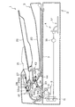
以下、図面を参照しつつ本発明に係る原稿搬送装置の実施形態を詳細に説明する。図1に示すように本発明の原稿搬送装置1は、画像読取部4を有する本体ユニット2と、この本体ユニット2の上方に開閉可能に取り付けられる搬送読取ユニット3とを備えて構成されている。   DESCRIPTION OF EMBODIMENTS Hereinafter, an embodiment of a document conveying device according to the present invention will be described in detail with reference to the drawings. As shown in FIG. 1, the document conveying apparatus 1 according to the present invention includes a main body unit 2 having an image reading unit 4, and a conveying / reading unit 3 attached to the upper side of the main body unit 2 so as to be opened and closed. .

画像読取部4は、光学部5を固定した状態で第1のコンタクトガラス6の上面を通過する原稿を読み取る。また、本体ユニット2の上面には、原稿を載置するための平面スペースを有する第2のコンタクトガラス7が設けられ、このコンタクトガラス7上にセットされた原稿に対しては前記画像読取部4の光学部5が移動することによって読み取ることができる。   The image reading unit 4 reads a document passing through the upper surface of the first contact glass 6 with the optical unit 5 fixed. Further, a second contact glass 7 having a plane space for placing a document is provided on the upper surface of the main unit 2, and the image reading unit 4 is arranged for the document set on the contact glass 7. It can be read by moving the optical unit 5.

前記画像読取部4は、ランプなどの光源10、複数のミラー11、レンズ16、CCDなどの光電変換素子17等を備える。搬送あるいは載置された原稿には、第1のコンタクトガラス6又は第2のコンタクトガラス7を介して光源10から発せられる光が照射される。そして、原稿面に照射されて反射した光を複数のミラー11によって何度か反射させた後、レンズ16を介して光電変換素子17で光電変換することで原稿の画像が読み取られる。   The image reading unit 4 includes a light source 10 such as a lamp, a plurality of mirrors 11, a lens 16, a photoelectric conversion element 17 such as a CCD, and the like. The document that is conveyed or placed is irradiated with light emitted from the light source 10 via the first contact glass 6 or the second contact glass 7. Then, the light irradiated and reflected on the document surface is reflected several times by the plurality of mirrors 11 and then photoelectrically converted by the photoelectric conversion element 17 through the lens 16 to read the image of the document.

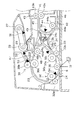
次に、搬送読取ユニット3の構成について説明する。この搬送読取ユニット3は、図1及び図2に示したように、複数枚の原稿を載置可能な給紙トレイ20と、載置された複数枚の原稿を繰出位置に昇降する支持トレイ21と、読取処理の終了した原稿を収納する排紙トレイ22とを備えている。   Next, the configuration of the transport reading unit 3 will be described. As shown in FIGS. 1 and 2, the transport reading unit 3 includes a paper feed tray 20 on which a plurality of documents can be placed, and a support tray 21 that raises and lowers the placed documents to a feeding position. And a paper discharge tray 22 for storing the document that has been read.

また、この搬送読取ユニット3には、給紙トレイ20上に積載されている複数枚の原稿から1枚ずつ給紙する給紙路23と、この給紙路23から第1のコンタクトガラス6を経由して延びる読取搬送路24と、この搬送路24から排紙トレイ22の排紙口に連なる排紙路25とからなる原稿の搬送手段を備える。   The transport reading unit 3 includes a paper feed path 23 that feeds one by one from a plurality of documents stacked on the paper feed tray 20, and a first contact glass 6 from the paper feed path 23. The apparatus includes a reading conveyance path 24 that extends through the sheet, and a document conveyance means that includes a discharge path 25 that extends from the conveyance path 24 to a discharge port of the discharge tray 22.

前記支持トレイ21の下流側には、この支持トレイ21の上昇によって当接された原稿を繰り出すための繰出ローラ27と、繰り出された原稿を給送する給紙ローラ28と、この給紙ローラ28に圧接して原稿を1枚ずつ分離する分離パッド29と、1枚ずつ分離されて給紙される原稿の先端を突き当てて整合した後に第1のコンタクトガラス6に向けて送り出すレジストローラ対30とを備える。   On the downstream side of the support tray 21, a feed roller 27 for feeding out the original abutted by the raising of the support tray 21, a paper feed roller 28 for feeding the fed original, and the paper feed roller 28. A separation pad 29 that presses against and separates the originals one by one, and a registration roller pair 30 that feeds toward the first contact glass 6 after abutting and aligning the leading edges of the originals that are separated and fed one by one. With.

前記読取搬送路24には、第1のコンタクトガラス6の上流側に配置される第1リードローラ対32と、下流側に配置される第2リードローラ対33とが設けられている。   The reading conveyance path 24 is provided with a first lead roller pair 32 disposed on the upstream side of the first contact glass 6 and a second lead roller pair 33 disposed on the downstream side.

また、前記排紙トレイ22の前段には、一の面(表面)の画像が読み取られた原稿を一時的に退避させた後、再搬送させるための第1スイッチバック部41と、表裏両面の画像が読み取られた原稿を一時的に退避させた後、排紙トレイ22に収容させるための第2スイッチバック部42とを備えている。第1スイッチバック部41は、前記排紙路25と兼用の第1スイッチバックパス45と、この第1スイッチバックパス45の上流側からレジストローラ対30に向けて合流する再搬送パス47とを有するとともに、前記第1スイッチバックパス45の端部に設けられ、この第1スイッチバックパス45上に一時的に退避される原稿のニップ圧が可変可能な第1スイッチバックローラ対43、前記再搬送パス47上に設けられる待機ローラ対48を有して構成されている。前記第1スイッチバックローラ対43及び待機ローラ対48は、一方が正転、反転駆動が可能な駆動ローラ43a,48aで、他方が回転フリーの従動ローラ43b,48bで構成され、互いに圧接及び離間可能に配置される。なお、前記従動ローラ43bには、後述するニップ圧調整手段を備える。以下、正転とは原稿を下流側に送り出すような反時計回りの回転をいい、反転とは原稿を上流側に送り戻すような時計回りの回転をいう。   The first stage of the paper discharge tray 22 includes a first switchback portion 41 for temporarily retracting a document on which an image on one surface (front surface) has been read and then transporting it again. A second switchback unit 42 is provided for temporarily storing the document from which the image has been read and then storing it in the paper discharge tray 22. The first switchback unit 41 includes a first switchback path 45 that also serves as the paper discharge path 25, and a re-transport path 47 that merges from the upstream side of the first switchback path 45 toward the registration roller pair 30. And a first switchback roller pair 43 provided at an end of the first switchback path 45 and capable of varying the nip pressure of the document temporarily retracted on the first switchback path 45, A standby roller pair 48 provided on the transport path 47 is provided. The first switchback roller pair 43 and the standby roller pair 48 are constituted by drive rollers 43a and 48a, one of which can be rotated forward and reversely, and the other of which are driven free rotation rollers 43b and 48b. Arranged as possible. The driven roller 43b is provided with nip pressure adjusting means described later. Hereinafter, forward rotation refers to counterclockwise rotation that feeds the document downstream, and reversal refers to clockwise rotation that feeds the document upstream.

前記第2スイッチバック部42は、第2リードローラ対33から排紙トレイ22の下方に向けて延びる第2スイッチバックパス46と、この第2スイッチバックパス46の上流側から折り返して前記第1スイッチバックパス45に合流する反転排紙パス49とを有するとともに、前記第2スイッチバックパス46と反転排紙パス49とが分岐する部分の近傍に第2スイッチバックローラ対44が設けられる。この第2スイッチバックローラ対44は、一方が正転、反転駆動が可能な駆動ローラ44aで、他方が回転フリーの従動ローラ44bで構成され、互いに圧接及び離間可能に配置される。   The second switchback portion 42 is folded from the second switchback path 46 extending from the second read roller pair 33 toward the lower side of the paper discharge tray 22 and the upstream side of the second switchback path 46. A reverse discharge path 49 that merges with the switchback path 45 is provided, and a second switchback roller pair 44 is provided in the vicinity of a portion where the second switchback path 46 and the reverse discharge path 49 are branched. One of the second switchback roller pair 44 is a drive roller 44a capable of normal rotation and reverse rotation, and the other is a rotation-free driven roller 44b, which are disposed so as to be capable of being pressed against and separated from each other.

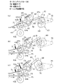
図4は前記第1スイッチバックローラ対43に設けられるニップ圧調整手段61の構成及び動作を示したものである。このニップ圧調整手段61は、ニップ圧を回転によって切換えるためのカム部材63と、このカム部材63の回転運動を前記従動ローラ43bに伝達するための伝達部材62とを備える。   FIG. 4 shows the configuration and operation of the nip pressure adjusting means 61 provided in the first switchback roller pair 43. The nip pressure adjusting means 61 includes a cam member 63 for switching the nip pressure by rotation, and a transmission member 62 for transmitting the rotational motion of the cam member 63 to the driven roller 43b.

前記伝達部材62は、前記従動ローラ43bとカム部材63との略中間地点を共有回転部66とし、この共有回転部66から従動ローラ43b側に延びる第1揺動部64と、カム部材63側に延びる第2揺動部65とを有して構成されている。前記第1揺動部64は、前記従動ローラ43bの従動回転軸43cを上下方向から挟むような断面コ字状の空間部を構成する一対の第1揺動腕部64a,64b及び前記共有回転部66の上方に突出する離間レバー67とを有する。前記コ字状の空間部は、前記従動回転軸43cの径よりも広く設定され、第1揺動部64の上下往復動によって、従動回転軸43cが一対の第1揺動腕部64a,64bのいずれか一方にのみ当接するようになっている。また、第2揺動部65は、カム部材63に備わる偏心カム68の回転面上に一端が載置される第2揺動腕部65a及び前記共有回転部66の上方に前記離間レバー67と対向するように突出する操作レバー69とを備える。   The transmission member 62 has a shared rotation portion 66 at a substantially intermediate point between the driven roller 43b and the cam member 63, a first swinging portion 64 extending from the shared rotation portion 66 to the driven roller 43b, and the cam member 63 side. And a second oscillating portion 65 extending in the direction. The first swinging portion 64 includes a pair of first swinging arm portions 64a and 64b that form a U-shaped space portion that sandwiches the driven rotation shaft 43c of the driven roller 43b from above and below, and the shared rotation. And a separation lever 67 protruding above the portion 66. The U-shaped space is set to be wider than the diameter of the driven rotating shaft 43c, and the driven rotating shaft 43c is paired with a pair of first swinging arm portions 64a and 64b by the reciprocating motion of the first swinging portion 64. Only one of them is brought into contact. The second swinging portion 65 includes a second swinging arm portion 65 a whose one end is placed on the rotation surface of the eccentric cam 68 provided in the cam member 63 and the separation lever 67 above the common rotation portion 66. And an operation lever 69 protruding so as to face each other.

また、前記伝達部材62には、ニップ圧を加えるための3種類のバネ部材を備える。第1バネ71は、前記従動回転軸43cを駆動ローラ43a側に付勢する板バネによって構成されている。第2バネ72は、第1揺動部64と第2揺動部65がそれぞれ回転可能に連結されている共有回転部66に配置されるトグルバネである。また、第3バネ73は、一端が前記操作レバー69の上端部に取り付けられ、他端が装置本体のカム部材63側に固定される引張りバネである。   The transmission member 62 includes three types of spring members for applying nip pressure. The first spring 71 is configured by a plate spring that urges the driven rotating shaft 43c toward the drive roller 43a. The second spring 72 is a toggle spring disposed in the shared rotating unit 66 in which the first swinging unit 64 and the second swinging unit 65 are rotatably connected. The third spring 73 is a tension spring having one end attached to the upper end of the operation lever 69 and the other end fixed to the cam member 63 side of the apparatus main body.

前記カム部材63は、タイミングベルト74を介してカムモータ75の回転力を受けるカム駆動軸76と、このカム駆動軸76から回転半径の異なる3つの回転面A,B,Cを有する偏心カム68とを有して構成されている。   The cam member 63 includes a cam drive shaft 76 that receives the rotational force of the cam motor 75 via a timing belt 74, and an eccentric cam 68 having three rotation surfaces A, B, and C having different rotation radii from the cam drive shaft 76. It is comprised.

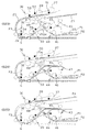
次に、前記ニップ圧調整手段61の動作について説明する。図4(a)は、従動ローラ43bを駆動ローラ43aから離間させる際の動作を示したものである。この動作は、前記偏心カム68がカム駆動軸76から最も近い回転面Aに前記第2揺動腕部65aが当接する位置に回転してきたときに作動する。この動作によって、前記第2揺動腕部65aが時計回りに回動すると同時に、操作レバー69が第3バネ73の付勢力によって離間レバー67を時計回りの方向に押圧する。この離間レバー67の回動によって、下側の第1揺動腕部64bが従動回転軸43cを持ち上げるようにして時計回りにスライドさせる。この従動回転軸43cのスライドによって、従動ローラ43bが駆動ローラ43aから離間する。なお、このような駆動ローラ43aの離間操作を行わせるためには、第3バネ73の付勢力(F3)が第1バネ71と第2バネ72を合わせた付勢力(F1+F2)よりも大きいことが条件とされる。   Next, the operation of the nip pressure adjusting means 61 will be described. FIG. 4A shows an operation when the driven roller 43b is separated from the driving roller 43a. This operation is activated when the eccentric cam 68 is rotated to a position where the second swinging arm portion 65a contacts the rotation surface A closest to the cam drive shaft 76. By this operation, the second swing arm portion 65 a rotates clockwise, and at the same time, the operation lever 69 presses the separation lever 67 in the clockwise direction by the urging force of the third spring 73. By the rotation of the separation lever 67, the lower first swing arm portion 64b slides clockwise so as to lift the driven rotation shaft 43c. The driven roller 43b is separated from the driving roller 43a by the slide of the driven rotating shaft 43c. Note that in order to perform such a separation operation of the drive roller 43a, the urging force (F3) of the third spring 73 is larger than the urging force (F1 + F2) of the first spring 71 and the second spring 72 combined. Is a condition.

図4(b)は、第1スイッチバックローラ対43によってニップされた2枚の原稿P1,P2が重なった状態で、それぞれ反対方向にすれ違いさせながら搬送させる場合に必要な小さいニップ圧に設定される動作を示したものである。この動作は、前記偏心カム68がカム駆動軸76から最も近い回転面Aと最も遠い回転面Cとの略中間位置である回転面Bに前記第2揺動腕部65aが当接する位置に回転してきたときに作動する。この動作によって、前記第2揺動腕部65aが反時計回りに回動するため、操作レバー69が第3バネ73の付勢力に抗して離間レバー67から離間する。この離間レバー67の離間によって、従動回転軸43cを支えている下側の第1揺動腕部64bが下降し、従動ローラ43bが駆動ローラ43aにニップ圧がかからない状態で当接する。このとき、従動回転軸43cは、第1揺動腕部64a,64bのいずれにも当接しない状態となり、第1バネ71の付勢力(F1)のみによって、従動ローラ43bが駆動ローラ43aにニップされた状態となる。   FIG. 4B shows a small nip pressure required when the two originals P1 and P2 nipped by the first switchback roller pair 43 are overlapped and conveyed while passing in opposite directions. This shows the operation. In this operation, the eccentric cam 68 rotates to a position where the second swinging arm portion 65a abuts on the rotation surface B which is a substantially intermediate position between the rotation surface A closest to the cam drive shaft 76 and the rotation surface C farthest from the cam drive shaft 76. It works when you do. By this operation, the second swinging arm portion 65 a rotates counterclockwise, so that the operation lever 69 is separated from the separation lever 67 against the urging force of the third spring 73. By the separation of the separation lever 67, the lower first swinging arm portion 64b supporting the driven rotating shaft 43c is lowered, and the driven roller 43b comes into contact with the driving roller 43a in a state where no nip pressure is applied. At this time, the driven rotating shaft 43c is not in contact with any of the first swinging arm portions 64a and 64b, and the driven roller 43b is nipped to the driving roller 43a only by the urging force (F1) of the first spring 71. It will be in the state.

図4(c)は、第1スイッチバックローラ対43によってニップされた2枚の原稿P1,P2が重なった状態で、そのまま同一方向に搬送させる場合に必要な大きいニップ圧に設定される動作を示したものである。この動作は、前記偏心カム68がカム駆動軸76から最も遠い回転面Cに第2揺動腕部65aが当接する位置に回転してきたときに作動する。この動作によって、前記第2揺動腕部65aが前記図4(b)の位置からさらに反時計回りに回動する。これによって、第2バネ72の付勢力(F2)が第1揺動部64に作用して反時計回りに回動し、上側の第1揺動腕部64aで従動回転軸43cを駆動ローラ43a側に押圧する。この第2バネ72の付勢力(F2)と前記第1バネ71の付勢力(F1)とが合わさった力で従動ローラ43bが駆動ローラ43aにニップされた状態となる。   FIG. 4C shows an operation for setting a large nip pressure required when the two originals P1 and P2 nipped by the first switchback roller pair 43 are overlapped and conveyed in the same direction as they are. It is shown. This operation is activated when the eccentric cam 68 is rotated to a position where the second swinging arm portion 65a contacts the rotation surface C farthest from the cam drive shaft 76. By this operation, the second swing arm portion 65a is further rotated counterclockwise from the position shown in FIG. 4B. As a result, the urging force (F2) of the second spring 72 acts on the first swinging portion 64 and rotates counterclockwise, and the upper first swinging arm portion 64a causes the driven rotation shaft 43c to move to the drive roller 43a. Press to the side. The driven roller 43b is nipped by the driving roller 43a by the force of the urging force (F2) of the second spring 72 and the urging force (F1) of the first spring 71.

また、前記第2リードローラ対33の下流側には、原稿の読み取り過程に応じて、前記第1スイッチバックパス45と第2スイッチバックパス46のいずれかに向けて原稿の流れを交互に切換えるための切換手段が設けられる。この切換手段は、3方向のパス面を有し、この3方向のパス面が回転軸36によって回動可能な切換フラッパー34によって構成されている。この切換フラッパー34は、それぞれのパス面が原稿の厚み幅の範囲内で回動可能となっている。第1パス面34aは第1スイッチバック部41に、第2パス面34bは第2スイッチバック部42に、第3パス面34cは排紙トレイ22に向けてそれぞれ原稿を案内するために設けられている。   In addition, on the downstream side of the second read roller pair 33, the flow of the document is alternately switched toward either the first switchback path 45 or the second switchback path 46 in accordance with the document reading process. Switching means is provided. This switching means has a three-way path surface, and the three-way path surface is constituted by a switching flapper 34 that can be rotated by a rotating shaft 36. The switching flapper 34 can be rotated within the range of the thickness width of the document. The first path surface 34 a is provided for guiding the document to the first switchback portion 41, the second path surface 34 b is provided for the second switchback portion 42, and the third path surface 34 c is provided for guiding the document toward the paper discharge tray 22. ing.

また、図2に示したように、原稿が通過する各所には各種のセンサが設けられている。繰出ローラ27の近傍には支持トレイ21から給紙されてくる原稿を検出するエンプティセンサ51、給紙ローラ28の先には1枚に分離された原稿を検出する分離センサ52が設けられる。また、第1のコンタクトガラス6の上流側の搬送路にはレジストセンサ53、リードセンサ54が設けられ、下流側の搬送路には反転センサ55、反転排出センサ56がそれぞれ配置される。なお、各センサの働きについては、後述する駆動系のタイミングチャート及び動作説明図の中で詳細に説明する。   Also, as shown in FIG. 2, various sensors are provided at various places where the document passes. An empty sensor 51 for detecting a document fed from the support tray 21 is provided in the vicinity of the feeding roller 27, and a separation sensor 52 for detecting a document separated into one sheet is provided at the tip of the paper feed roller 28. In addition, a registration sensor 53 and a lead sensor 54 are provided on the upstream conveyance path of the first contact glass 6, and a reverse sensor 55 and a reverse discharge sensor 56 are respectively disposed on the downstream conveyance path. The function of each sensor will be described in detail in a drive system timing chart and an operation explanatory diagram to be described later.

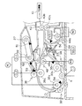
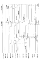
図3は上記各ローラ対の駆動系を示したものである。主に回転駆動を行うモータは3系統(M1,M2,M3)、ローラ対の離間制御を行うソレノイドは1系統(SOL1)備えている。前記モータM1は、給紙ローラ28、レジストローラ対30の駆動ローラ30a及び第1リードローラ対32の駆動ローラ32aに供給されており、そのうちの給紙ローラ28とレジストローラ対30の駆動ローラ30aには電磁クラッチCL1,CL2を介して接続されている。このモータM1は、原稿を第1のプラテンガラス6に向けて搬送させるために回転駆動され、前記給紙ローラ28、レジストローラ対30の駆動ローラ30aは、電磁クラッチCL1,CL2によって所定のタイミングで停止制御が可能となっている。モータM2は、第1スイッチバックローラ対43の駆動ローラ43a及び第2スイッチバックローラ対44の駆動ローラ44aに供給され、正転、反転、停止制御が可能となっている。また、モータM3は待機ローラ対48の駆動ローラ48aに供給され、正転及び停止制御が可能となっている。   FIG. 3 shows the drive system of each roller pair. There are mainly three motors (M1, M2, M3) for rotational driving, and one system (SOL1) for controlling the roller pair separation. The motor M1 is supplied to the paper feed roller 28, the drive roller 30a of the registration roller pair 30 and the drive roller 32a of the first lead roller pair 32, of which the drive roller 30a of the paper feed roller 28 and the registration roller pair 30. Are connected via electromagnetic clutches CL1 and CL2. The motor M1 is rotationally driven to convey the document toward the first platen glass 6, and the driving roller 30a of the paper feed roller 28 and the registration roller pair 30 is driven at a predetermined timing by electromagnetic clutches CL1 and CL2. Stop control is possible. The motor M2 is supplied to the drive roller 43a of the first switchback roller pair 43 and the drive roller 44a of the second switchback roller pair 44, and can perform forward rotation, reverse rotation, and stop control. Further, the motor M3 is supplied to the driving roller 48a of the standby roller pair 48 so that normal rotation and stop control are possible.

また、SOL1は、切換フラッパー34の回転軸36の近傍に設けられ、時計回り及び反時計回りに所定の回転幅で回転制御される。なお、前記第1スイッチバックローラ対43の従動ローラ43bは、前述したように、ニップ圧調整手段61によってニップ圧が可変となるように制御される。   SOL1 is provided in the vicinity of the rotation shaft 36 of the switching flapper 34, and is controlled to rotate clockwise and counterclockwise with a predetermined rotation width. The driven roller 43b of the first switchback roller pair 43 is controlled so that the nip pressure is variable by the nip pressure adjusting means 61 as described above.

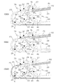
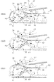
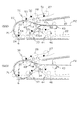
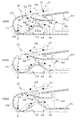
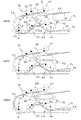
次に、図7〜図16に示した各ステップ(S00)〜(S28)に基づき、また、図5,図6のタイミングチャートを参照しつつ本発明の原稿搬送装置の動作を原稿の流れに沿って説明する。最初に給紙トレイ20上に原稿が載置されたことをエンプティセンサ51が検知すると、給紙モータM1が駆動し、電磁クラッチCL1をONすると繰出ローラ27及び給紙ローラ28が回転駆動する。これによって、前記給紙トレイ20上に載置された最上位の原稿が順次繰り出され、分離パッド29によって1枚の原稿P1に分離される。なお、原稿の給紙開始時におけるイニシャル動作で第1スイッチバックローラ対43及び第2スイッチバックローラ対44は離間する位置にセットされ、また切換フラッパー34は、第1スイッチバックパス45に案内されるような向きにセットされる(S00)。   Next, based on the steps (S00) to (S28) shown in FIG. 7 to FIG. 16, and referring to the timing charts of FIG. 5 and FIG. It explains along. When the empty sensor 51 first detects that an original is placed on the paper feed tray 20, the paper feed motor M1 is driven. When the electromagnetic clutch CL1 is turned on, the feeding roller 27 and the paper feed roller 28 are rotationally driven. As a result, the uppermost document placed on the sheet feed tray 20 is sequentially fed out and separated into one document P1 by the separation pad 29. Note that the initial switchback roller pair 43 and the second switchback roller pair 44 are set in a separated position by the initial operation at the start of document feeding, and the switching flapper 34 is guided to the first switchback path 45. (S00).

前記分離パッド29を経た原稿P1の先端をレジストセンサ53が検知すると、その検知した時点から原稿P1を所定量搬送することによって、レジストローラ対30のニップ部分に原稿P1の先端が突き当たることで整合され、スキューが取り除かれる(S01)。   When the registration sensor 53 detects the leading edge of the document P1 that has passed through the separation pad 29, the document P1 is transported by a predetermined amount from the point of detection, thereby aligning the leading edge of the document P1 with the nip portion of the registration roller pair 30. The skew is removed (S01).

その後、電磁クラッチCL2がONされ、レジストローラ対30が反時計方向に回転駆動する。そして、原稿P1は駆動される第1、第2リードローラ対32、33によってU字状に延びる給紙路23に沿って搬送され、表面と裏面が反転した状態で第1のプラテンガラス6上を通過する。この第1のプラテンガラス6上を通過する際に原稿P1の表面が読み取られる(S02)。   Thereafter, the electromagnetic clutch CL2 is turned on, and the registration roller pair 30 is driven to rotate counterclockwise. The original P1 is conveyed along the U-shaped paper feed path 23 by the first and second read roller pairs 32 and 33 to be driven, and the first platen glass 6 is placed on the first platen glass 6 in a state where the front surface and the back surface are reversed. Pass through. The surface of the document P1 is read when passing over the first platen glass 6 (S02).

前記第1のプラテンガラス6を通過した原稿P1は、切換フラッパー34を介して第1スイッチバックパス45に案内される。この1枚目の原稿P1の先端部が第1スイッチバックパス45に案内されていく間に、後端部が分離後センサ52で検知されると、2枚目の原稿P2の給送が給紙ローラ28によって開始され、レジストセンサ53が原稿P1の後端部を検出すると電磁クラッチCL2がOFFされ、レジストローラ対30は停止される(S03)。   The document P1 that has passed through the first platen glass 6 is guided to the first switchback path 45 via the switching flapper 34. If the trailing edge of the first document P1 is detected by the post-separation sensor 52 while the leading edge of the first document P1 is guided to the first switchback path 45, the second document P2 is fed. Starting with the paper roller 28, when the registration sensor 53 detects the trailing edge of the document P1, the electromagnetic clutch CL2 is turned off and the registration roller pair 30 is stopped (S03).

給紙された前記2枚目の原稿P2の先端はレジストローラ対30のニップ部分に突き当たって整合され、一旦原稿P2の搬送が停止される(S04)。   The leading edge of the fed second document P2 comes into contact with the nip portion of the registration roller pair 30 and is aligned, and the conveyance of the document P2 is temporarily stopped (S04).

そして、電磁クラッチCL1をOFFした時点から所定の時間が経過した後に電磁クラッチCL2をONする。これによって、レジストローラ対30が駆動して原稿P2が第1のプラテンガラス6に向けて送り出される。なお、前述の所定時間は先に給紙された原稿P1と原稿P2との間隔を一定に保つために予め定められた時間である。一方、原稿P1の先端部が反転センサ55で検知されると反転排出モータM2が正転駆動し、ニップ圧調整手段61が図4(b)に示したように第1バネ71の付勢力(F1)のみによって、従動ローラ43bが駆動ローラ43aにニップされる。これによって、第1スイッチバックローラ対43の駆動ローラ43aと従動ローラ43bが当接した状態で回転駆動され、原稿P1が排紙トレイ22側に向けてさらに前進される(S05)。   Then, after a predetermined time has elapsed since the electromagnetic clutch CL1 was turned off, the electromagnetic clutch CL2 is turned on. As a result, the registration roller pair 30 is driven, and the document P2 is sent out toward the first platen glass 6. The above-mentioned predetermined time is a predetermined time for keeping the interval between the original P1 and the original P2 fed in advance. On the other hand, when the leading edge of the document P1 is detected by the reverse sensor 55, the reverse discharge motor M2 is driven to rotate forward, and the nip pressure adjusting means 61 is biased by the first spring 71 as shown in FIG. The driven roller 43b is nipped by the driving roller 43a only by F1). As a result, the drive roller 43a of the first switchback roller pair 43 and the driven roller 43b are rotationally driven, and the document P1 is further advanced toward the discharge tray 22 side (S05).

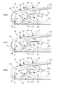
原稿P2が前記第1のプラテンガラス6に向けて搬送される間に、第1のプラテンガラス6を通過した原稿P1は、その後端部が反転センサ55で検知されてから一定時間が経過した時点で反転排出モータM2を停止する。これによって、第1スイッチバックローラ対でニップされた状態で停止し、その後反転排出モータM2を逆転駆動することで第1スイッチバックローラ対43は逆回転駆動され、原稿P1がスイッチバックされる(S06)〜(S07)。   While the original P2 is conveyed toward the first platen glass 6, the original P1 that has passed through the first platen glass 6 has passed a certain period of time after its rear end is detected by the reverse sensor 55. Then, the reverse discharge motor M2 is stopped. Thus, the first switchback roller pair 43 is stopped in a nipped state, and then the reverse discharge motor M2 is driven in reverse rotation, whereby the first switchback roller pair 43 is driven in reverse rotation and the document P1 is switched back ( S06) to (S07).

そして、第1スイッチバックローラ対43でスイッチバックされた原稿P1は再搬送パス47に沿って搬送される。そして、原稿P1の先端部が回転駆動する待機ローラ対48でニップされた後に待機モータM3を停止することによって、原稿P1は一旦停止状態となる。原稿P1が待機ローラ対48でニップ保持されて停止されると、ニップ圧調整手段61が図4(a)に示したように第3バネ73の付勢力(F3)によって、従動ローラ43bを駆動ローラ43aから離間させ、反転排出モータM2を正転駆動に切換える。この状態で、第1のコンタクトガラス6を通過した原稿P2を第1スイッチバックパス45内に搬送し、第1スイッチバックパス45内で停止された原稿P1の下方を搬送され、排紙トレイ22側に搬送される。なお、このとき第1スイッチバックローラ対43を離間させているので原稿P2の先端部は支障なく第1スイッチバックパス45内を排紙トレイ側に搬送される。また離間した第1スイッチバックローラ対43の駆動ローラ43aを正回転駆動しているので、原稿P2には駆動ローラ43aの接触した際の搬送力が付与されスムーズに送られる(S08)〜(S09)。   The document P1 switched back by the first switchback roller pair 43 is transported along the re-transport path 47. Then, after the front end portion of the document P1 is nipped by the standby roller pair 48 that is rotationally driven, the standby motor M3 is stopped, whereby the document P1 is temporarily stopped. When the original P1 is nipped by the standby roller pair 48 and stopped, the nip pressure adjusting means 61 drives the driven roller 43b by the urging force (F3) of the third spring 73 as shown in FIG. The reverse discharge motor M <b> 2 is switched to the normal rotation drive while being separated from the roller 43 a. In this state, the document P2 that has passed through the first contact glass 6 is transported into the first switchback path 45, is transported under the document P1 stopped in the first switchback path 45, and is discharged into the paper discharge tray 22. Conveyed to the side. At this time, since the first switchback roller pair 43 is separated, the leading edge of the document P2 is conveyed to the discharge tray side in the first switchback path 45 without any problem. Further, since the driving roller 43a of the separated first switchback roller pair 43 is driven to rotate in the forward direction, the document P2 is supplied with a conveying force when the driving roller 43a comes into contact and is smoothly fed (S08) to (S09). ).

前記原稿P2がレジストセンサ53を通過する電磁クラッチCL2をOFFする。また原稿P2の後端部がレジストセンサ53で検知された時点から所定時間経過後に待機モータM3を駆動する。これによって、再搬送パス47上で停止している原稿P1の先端がレジストローラ対30に当接するように送り出される。この間、第1リードローラ対32、第2リードローラ対33、第1スイッチバックローラ対43の正回転駆動によって、原稿P2が第1スイッチバックパス45上で原稿P1とすれ違うようにして搬送される。このとき、第1スイッチバックローラ対43は離間した状態で、原稿P1と原稿P2の第1スイッチバックパス内の一部でそれぞれ異なる方向に搬送される。そして、原稿P2の後端部がリードセンサ54で検知され、原稿P2の後端部が第1コンタクトガラス6の読取位置に到達する時間が経過した後に、ニップ圧調整手段61が図4(b)に示したように第1バネ71の付勢力のみによって、従動ローラ43bが駆動ローラ43aにニップされる。これによって、第1スイッチバックローラ対43が原稿P1と原稿P2を重ねて圧接し、その状態で原稿P1と原稿P2は第1スイッチバックパス内の一部でそれぞれ相反する方向に搬送されることとなるが、駆動ローラ43aの摩擦係数が原稿と従動ローラ43bの摩擦係数より高く設定しているので、従動ローラ43bと原稿P1に挟まれた原稿P1は待機ローラ48、レジストローラ対30、第1リードローラ対43によって原稿読取4に向けて送られ、駆動ローラ43aと原稿P1に挟まれた原稿P2は駆動ローラ43bによって原稿P1に抗して排紙トレイ22側に送られる(S10)〜(S11)。   The electromagnetic clutch CL2 through which the original P2 passes the registration sensor 53 is turned off. Further, the standby motor M3 is driven after a predetermined time has elapsed since the trailing edge of the document P2 was detected by the registration sensor 53. As a result, the leading edge of the document P1 stopped on the re-conveyance path 47 is sent out so as to contact the registration roller pair 30. During this time, the original P2 is conveyed on the first switchback path 45 so as to pass the original P1 by the forward rotation of the first read roller pair 32, the second read roller pair 33, and the first switchback roller pair 43. . At this time, the first switchback roller pair 43 is transported in different directions in a part of the first switchback path of the document P1 and the document P2 while being separated. Then, after the trailing edge of the document P2 is detected by the lead sensor 54 and the time for the trailing edge of the document P2 to reach the reading position of the first contact glass 6 has elapsed, the nip pressure adjusting means 61 performs the operation shown in FIG. ), The driven roller 43b is nipped by the driving roller 43a only by the urging force of the first spring 71. As a result, the first switchback roller pair 43 overlaps and presses the original P1 and the original P2, and in this state, the original P1 and the original P2 are conveyed in opposite directions in a part of the first switchback path. However, since the friction coefficient of the driving roller 43a is set higher than the friction coefficient of the document and the driven roller 43b, the document P1 sandwiched between the driven roller 43b and the document P1 is the standby roller 48, the registration roller pair 30, the first roller The document P2 that is sent toward the document reading 4 by the one read roller pair 43 and is sandwiched between the driving roller 43a and the document P1 is sent to the paper discharge tray 22 side against the document P1 by the driving roller 43b (S10). (S11).

そして、原稿P2の後端部が反転センサ55に検知されてから一定時間後に反転排出モータM2を正転駆動から逆転駆動に切換えることで第1スイッチバックローラ対43は正転駆動から逆回転駆動されて原稿P2がスイッチバックされる(S12)〜(S14)。このとき、原稿P1の後端部は第1スイッチバックローラ対43のニップ位置を通過しており、原稿P2のスイッチバック動作に影響しない。スイッチバックされた原稿P2は再搬送パスに沿って搬送され、待機ローラ対48にニップされると待機モータM3を停止して原稿P1を待機させる。   The first switchback roller pair 43 is driven from the normal rotation drive to the reverse rotation by switching the reverse discharge motor M2 from the normal rotation drive to the reverse rotation drive after a certain period of time after the trailing edge of the document P2 is detected by the reverse sensor 55. Then, the document P2 is switched back (S12) to (S14). At this time, the rear end portion of the document P1 passes through the nip position of the first switchback roller pair 43 and does not affect the switchback operation of the document P2. The switched-back original P2 is conveyed along the re-conveying path, and when nipped by the standby roller pair 48, the standby motor M3 is stopped to make the original P1 stand by.

一方、1枚目の原稿P1は、裏面が読み取られた後、先端部が切換フラッパー34によって切換えられた経路を通って第2スイッチバックパス46へ案内される(S14)。なお、切換フラッパー34は、2枚目の原稿P2の後端部が反転センサ55で検知されると時計回りに回動して第2スイッチバックパス46へ連絡する経路を形成する。また、原稿P1の後端部がリードセンサ24に検知されるとソレノイドSOL1がON(吸着)され、第2スイッチバックローラ44が圧接状態となる(S16)。   On the other hand, after the back side of the first document P1 is read, the first document P1 is guided to the second switchback path 46 through a route where the leading end is switched by the switching flapper 34 (S14). Note that the switching flapper 34 forms a path that rotates clockwise to communicate with the second switchback path 46 when the rear end portion of the second document P2 is detected by the reverse sensor 55. When the rear end portion of the document P1 is detected by the read sensor 24, the solenoid SOL1 is turned on (sucked), and the second switchback roller 44 is brought into a pressure contact state (S16).

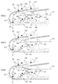
待機ローラ対48にニップして待機された原稿P2は、原稿P1の後端部がレジストセンサ53で検知した後に待機モータM3を駆動して、停止されたレジストローラ対30に当接し、先端が整合される。そして、電磁クラッチCL2をONすることでレジストローラ対30を回転駆動させて原稿を原稿読取部4に向けて再搬送する(S14)〜(S16)。   The document P2 that is nipped by the standby roller pair 48 and waits is driven by the standby motor M3 after the trailing edge of the document P1 is detected by the registration sensor 53 to come into contact with the stopped registration roller pair 30, and the leading edge of the document P2 Be aligned. Then, by turning on the electromagnetic clutch CL2, the registration roller pair 30 is rotationally driven, and the document is conveyed again toward the document reading unit 4 (S14) to (S16).

原稿P1が第2スイッチバックパス46に搬送され、その後端部が反転センサ55で検知されるとその所定時間後に反転排出モータM2を逆転駆動から正転駆動に切換える(S16)〜(S17)。これによって、第2スイッチバックローラ対44を正回転駆動から逆回転駆動に切換わり、原稿P1をスイッチバックさせる。スイッチバックされた原稿P1は反転排出経路26に沿って第1スイッチバックローラ対43に送られ、第1スイッチバックローラ対43によって排紙トレイ22に排出される(S16)〜(S21)。   When the original P1 is conveyed to the second switchback path 46 and the rear end thereof is detected by the reverse sensor 55, the reverse discharge motor M2 is switched from reverse drive to forward drive after a predetermined time (S16) to (S17). As a result, the second switchback roller pair 44 is switched from the forward rotation drive to the reverse rotation drive, and the document P1 is switched back. The switched-back document P1 is sent to the first switchback roller pair 43 along the reverse discharge path 26, and is discharged to the discharge tray 22 by the first switchback roller pair 43 (S16) to (S21).

一方、原稿P2は原稿P1に続いて原稿読取部4に搬送されて裏面が読み取られ、第2スイッチバックパス46に搬送される。このとき、原稿P2の先端部を反転センサ55が検出するとソレノイド(SOL1)がOFF(吸着解除)されて第2のスイッチバックローラ44が離間する。そして、原稿P1と原稿P2が第2スイッチバックパス内ですれ違うようにして搬送される(S17)〜(S19)。また、原稿P1の後端部が反転排出センサ55で検知されるとソレノイドSOL1がONして第2のスイッチバックローラ44が再び圧接する。これと同時に反転排出モータM2が正回転駆動から逆回転駆動に切換えられる。その後、反転排出モータM2が逆回転駆動から正回転駆動に切換えられ、第2スイッチバックローラ対44が正回転駆動から逆回転駆動に切り換わる。これによって、原稿P2がスイッチバックされ、反転排出経路26に沿って第1スイッチバックローラ対43に送られる。そして、第1スイッチバックローラ対43によって排紙トレイ22に排出される(S19)〜(S21)。   On the other hand, the original P2 is conveyed to the original reading unit 4 following the original P1, the back side is read, and is conveyed to the second switchback path 46. At this time, when the reversing sensor 55 detects the leading edge of the document P2, the solenoid (SOL1) is turned OFF (adsorption release), and the second switchback roller 44 is separated. Then, the document P1 and the document P2 are conveyed so as to pass each other in the second switchback path (S17) to (S19). Further, when the rear end portion of the document P1 is detected by the reverse discharge sensor 55, the solenoid SOL1 is turned ON and the second switchback roller 44 comes into pressure contact again. At the same time, the reverse discharge motor M2 is switched from forward rotation drive to reverse rotation drive. Thereafter, the reverse discharge motor M2 is switched from the reverse rotation drive to the normal rotation drive, and the second switchback roller pair 44 is switched from the normal rotation drive to the reverse rotation drive. As a result, the document P2 is switched back and sent to the first switchback roller pair 43 along the reverse discharge path 26. Then, the paper is discharged to the paper discharge tray 22 by the first switchback roller pair 43 (S19) to (S21).

3枚目の原稿P3は2枚目の原稿P2がレジストセンサ53を通過した時点から所定時間後に電磁クラッチCL1がONされ給紙が開始される。そして、この3枚目の原稿P3は、先の1枚目の原稿P1と同様に搬送され、3枚目に続く4枚目の原稿P4は2枚目の原稿P2と同様に搬送されることとなる(S18)〜(S28)。   The third original P3 is fed by a predetermined time after the second original P2 passes the registration sensor 53 and the electromagnetic clutch CL1 is turned on. The third original P3 is conveyed in the same manner as the first original P1, and the fourth original P4 following the third is conveyed in the same manner as the second original P2. (S18) to (S28).

2枚目の原稿P2が排紙トレイ22に排出される際に、原稿P2と第1スイッチバックパス41に送られた3枚目の原稿P3とが重なって排紙トレイ22側に搬送される(S24)〜(S28)。このとき、ニップ圧調整手段61は、図4(c)に示したように第1バネ71と第2バネ72とが合わさった大きな付勢力(F1+F2)によって、従動ローラ43bが駆動ローラ43aにニップされ、原稿P2が先に第1スイッチバックローラ対43に到達し、その後に原稿P3は第1スイッチバックローラ対43に搬送される。つまり、ここでは原稿P2に対して原稿P3がずれた状態で排紙トレイ22側に向けて同一搬送される。そして、原稿P4の後端部が反転センサ56で検知した時点から所定時間後に正転駆動している反転排出モータM2を停止する。これによって、第1スイッチバックローラ対43は一旦停止される。このとき、原稿P2は排紙トレイ22に排出され、原稿P3の排紙トレイ22と異なる側の端部が第1スイッチバックローラ対43にニップされた状態となる。そして、この状態から反転排出モータM2を逆転駆動することで、第1スイッチバックローラ対43が逆回転駆動して原稿P3がスイッチバックされる。なお、第1スイッチバックローラ対43は原稿P3の先端が第1スイッチバックローラ対43に到達するまでは離間した状態で正転駆動され、原稿P3の先端が第1スイッチバックローラ対43に到達した時点で正転駆動のままニップされる(S22)〜(S25)。   When the second original P2 is discharged to the paper discharge tray 22, the original P2 and the third original P3 sent to the first switchback path 41 are overlapped and conveyed to the discharge tray 22 side. (S24) to (S28). At this time, as shown in FIG. 4C, the nip pressure adjusting means 61 causes the driven roller 43b to nip the drive roller 43a by the large urging force (F1 + F2) obtained by combining the first spring 71 and the second spring 72. Then, the document P2 reaches the first switchback roller pair 43 first, and then the document P3 is conveyed to the first switchback roller pair 43. That is, here, the original P3 is shifted toward the paper discharge tray 22 with the original P3 being displaced from the original P2. Then, the reverse discharge motor M2 that is normally driven after a predetermined time from the time when the rear end portion of the document P4 is detected by the reverse sensor 56 is stopped. Thereby, the first switchback roller pair 43 is temporarily stopped. At this time, the original P2 is discharged to the paper discharge tray 22, and the end of the original P3 on the side different from the paper discharge tray 22 is nipped by the first switchback roller pair 43. Then, when the reverse discharge motor M2 is driven in reverse from this state, the first switchback roller pair 43 is driven in reverse to switch back the document P3. The first switchback roller pair 43 is driven to rotate forward in a separated state until the leading edge of the document P3 reaches the first switchback roller pair 43, and the leading edge of the document P3 reaches the first switchback roller pair 43. At that time, the nipping is continued with the forward rotation driving (S22) to (S25).

前記第1スイッチバックパス45上を先行する原稿P2は、第1スイッチバックローラ対43によって排紙トレイ22に収容され、後続の原稿P3は、後端が反転センサ55で検出された位置で停止され、表面が読み取られた4枚目の原稿P4とすれ違うようにして再搬送パス47に送り出される。以降は図7から図16までの手順を繰り返すことによって、複数の連続した原稿の読取処理が行われる。   The document P2 that precedes the first switchback path 45 is accommodated in the paper discharge tray 22 by the first switchback roller pair 43, and the subsequent document P3 stops at the position where the trailing edge is detected by the reverse sensor 55. Then, the sheet is sent to the re-conveying path 47 so as to pass the fourth original P4 whose surface has been read. Thereafter, by repeating the procedure from FIG. 7 to FIG. 16, a plurality of continuous document reading processes are performed.

以上説明したように、本発明の原稿搬送装置では、スイッチバック部において、2枚の原稿を相反する方向にすれ違いさせながら、あるいは、2枚の原稿が重なった状態で同一方向に搬送させる際に、退避及び再搬送させる第1及び第2のスイッチバック部を設けた構造となっているため、先行する1枚目の原稿と後続の2枚目の原稿との間の間隔を詰めた状態で搬送及び表裏の両面読み取りを行わせることが可能となった。特に、ニップ圧調整手段によって、すれ違い搬送と同一搬送とで原稿をニップする力を可変可能としたことで、原稿の搬送がスムーズ且つ確実になり、連続読み取りのスピードアップ化とともに、原稿搬送装置全体の小型化も図られることとなった。   As described above, in the document conveying device of the present invention, when the two documents are passed in the opposite direction in the switchback unit or when the two documents are overlapped and conveyed in the same direction. Since the first and second switchback portions for retracting and re-transporting are provided, the gap between the preceding first document and the succeeding second document is reduced. It has become possible to perform both conveyance and front / back scanning. In particular, the nip pressure adjusting means makes it possible to change the force to nip the original between the same conveyance and the same conveyance, so that the conveyance of the original is smooth and reliable, the speed of continuous reading is increased, and the entire original conveyance apparatus The miniaturization of the system was also planned.

1 原稿搬送装置
2 本体ユニット
3 搬送読取ユニット
4 画像読取部
5 光学部
6 第1のコンタクトガラス
7 第2のコンタクトガラス
10 光源
11 ミラー
16 レンズ
17 光電変換素子
20 給紙トレイ
21 支持トレイ
22 排紙トレイ
23 給紙路
24 読取搬送路
25 排紙路
27 繰出ローラ
28 給紙ローラ
29 分離パッド
30 レジストローラ対
32 第1リードローラ対
33 第2リードローラ対
34 切換フラッパー
34a 第1パス面
34b 第2パス面
34c 第3パス面
35 押圧ローラ
36 回転軸
41 第1スイッチバック部
42 第2スイッチバック部
43 第1スイッチバックローラ対
43a 駆動ローラ
43b 従動ローラ
43c 従動回転軸
44 第2スイッチバックローラ対
44a 駆動ローラ
44b 従動ローラ
45 第1スイッチバックパス
46 第2スイッチバックパス
47 再搬送パス
48 待機ローラ対
48a 駆動ローラ
48b 従動ローラ
49 反転排紙パス
51 エンプティセンサ
52 分離センサ
53 レジストセンサ
54 リードセンサ
55 反転センサ
56 反転排出センサ
61 ニップ圧調整手段
62 伝達部材
63 カム部材
64 第1揺動部
64a,64b 第1揺動腕部
65 第2揺動部
65a 第2揺動腕部
66 共有回転部
67 離間レバー
68 偏心カム
69 操作レバー
71 第1バネ
72 第2バネ
73 第3バネ
74 タイミングベルト
75 カムモータ
76 カム駆動軸
DESCRIPTION OF SYMBOLS 1 Document conveying apparatus 2 Main body unit 3 Conveyance reading unit 4 Image reading part 5 Optical part 6 1st contact glass 7 2nd contact glass 10 Light source 11 Mirror 16 Lens 17 Photoelectric conversion element 20 Paper feed tray 21 Support tray 22 Paper discharge Tray 23 Paper feed path 24 Reading transport path 25 Paper discharge path 27 Feeding roller 28 Feeding roller 29 Separating pad 30 Registration roller pair 32 First lead roller pair 33 Second lead roller pair 34 Switching flapper 34a First path surface 34b Second Pass surface 34c Third pass surface 35 Pressure roller 36 Rotating shaft 41 First switchback portion 42 Second switchback portion 43 First switchback roller pair 43a Drive roller 43b Follower roller 43c Follower shaft 44 Second switchback roller pair 44a Drive roller 44b driven low 45 First switchback path 46 Second switchback path 47 Re-conveying path 48 Standby roller pair 48a Drive roller 48b Driven roller 49 Reverse paper discharge path 51 Empty sensor 52 Separation sensor 53 Registration sensor 54 Read sensor 55 Reverse sensor 56 Reverse discharge sensor 61 Nip pressure adjusting means 62 Transmission member 63 Cam member 64 First swing part 64a, 64b First swing arm part 65 Second swing part 65a Second swing arm part 66 Shared rotating part 67 Separating lever 68 Eccentric cam 69 Operation lever 71 First spring 72 Second spring 73 Third spring 74 Timing belt 75 Cam motor 76 Cam drive shaft

Claims (6)

給紙トレイから繰り出された原稿を画像読取部で読み取った後に排紙トレイへ排紙する原稿搬送路と、前記画像読取部と排紙トレイとの間に設けられ、画像読取部又は排紙トレイに向けて原稿を搬送させるスイッチバック部とを備えた原稿搬送装置であって、
前記スイッチバック部には、連続して給紙されてくる少なくとも2枚の原稿を重ねて搬送するスイッチバックローラ対と、このスイッチバックローラ対が原稿をニップするニップ圧をそれぞれの原稿の送り出し方向に応じて可変にするニップ圧調整手段とを備えたことを特徴とする原稿搬送装置。
An image reading unit or a discharge tray is provided between the image reading unit and the discharge tray, and a document conveyance path for discharging the document fed out from the paper feed tray to the discharge tray after being read by the image reading unit. A document transport device including a switchback unit that transports the document toward the
The switchback unit includes a pair of switchback rollers that transport at least two documents fed in succession, and a nip pressure at which the switchback roller pair nips the documents. And a nip pressure adjusting means that is variable according to the document conveying apparatus.
前記スイッチバックローラ対は、駆動ローラと、該駆動ローラの回転に追従するとともに、離間可能に配置される従動ローラとを備えて構成される請求項1に記載の原稿搬送装置。   The document conveying device according to claim 1, wherein the switchback roller pair includes a driving roller and a driven roller that follows the rotation of the driving roller and is arranged to be separated from the driving roller. 前記ニップ圧調整手段は、2枚の原稿が重なった状態で同一方向に搬送させる同一搬送と、2枚の原稿が重なった状態で互いに相反する方向に搬送させるすれ違い搬送とで前記スイッチバックローラ対のニップ圧を切換える請求項1に記載の原稿搬送装置。   The nip pressure adjusting means is configured to switch the pair of switchback rollers between the same conveyance that conveys two originals in the same direction when they overlap each other and the low conveyance that conveys the two originals in opposite directions when they overlap. The document conveying apparatus according to claim 1, wherein the nip pressure is switched. 前記ニップ圧調整手段は、前記同一搬送するときのスイッチバックローラ対のニップ圧よりも前記すれ違い搬送するときのスイッチバックローラ対のニップ圧が低くなるように調整する請求項3に記載の原稿搬送装置。   4. The document conveyance according to claim 3, wherein the nip pressure adjusting means adjusts the nip pressure of the switchback roller pair when the low-pass conveyance is lower than the nip pressure of the switchback roller pair when the same conveyance is performed. apparatus. 前記ニップ圧調整手段は、前記スイッチバックローラ対のニップ圧の切換えを行うカム部材と、このカム部材とローラとの間に掛け渡されニップ圧の切換えを前記スイッチバックローラ対に伝達する伝達部材と、前記スイッチバックローラ対に対して所定のニップ圧を加えるバネ部材とを備える請求項1に記載の原稿搬送装置。   The nip pressure adjusting means includes a cam member that switches the nip pressure of the switchback roller pair, and a transmission member that is spanned between the cam member and the roller and transmits the nip pressure switching to the switchback roller pair. And a spring member that applies a predetermined nip pressure to the switchback roller pair. 前記バネ部材は、2枚の原稿が重なった状態で互いに相反する方向に搬送させるすれ違い搬送の際に所定のニップ圧を加える第1バネと、2枚の原稿が重なった状態で同一方向に搬送させる同一搬送の際に所定のニップ圧を加える前記第1バネと第2バネとを備える請求項5に記載の原稿搬送装置。   The spring member conveys in the same direction when two originals overlap each other, and a first spring that applies a predetermined nip pressure when passing the two originals in a direction opposite to each other when they are overlapped. The document conveying apparatus according to claim 5, further comprising the first spring and the second spring that apply a predetermined nip pressure during the same conveyance.
JP2009299179A 2009-11-12 2009-12-29 Document carrying device Pending JP2011136825A (en)

Priority Applications (3)

Application Number Priority Date Filing Date Title
JP2009299179A JP2011136825A (en) 2009-12-29 2009-12-29 Document carrying device
CN201010541870.1A CN102060204B (en) 2009-11-12 2010-11-12 Original document feeder
US12/926,349 US8210515B2 (en) 2009-11-12 2010-11-12 Document transport apparatus

Applications Claiming Priority (1)

Application Number Priority Date Filing Date Title
JP2009299179A JP2011136825A (en) 2009-12-29 2009-12-29 Document carrying device

Publications (1)

Publication Number Publication Date
JP2011136825A true JP2011136825A (en) 2011-07-14

Family

ID=44348660

Family Applications (1)

Application Number Title Priority Date Filing Date
JP2009299179A Pending JP2011136825A (en) 2009-11-12 2009-12-29 Document carrying device

Country Status (1)

Country Link
JP (1) JP2011136825A (en)

Cited By (1)

* Cited by examiner, † Cited by third party
Publication number Priority date Publication date Assignee Title
JP2016060619A (en) * 2014-09-19 2016-04-25 富士ゼロックス株式会社 Transportation device, image reading device, and image formation device

Citations (2)

* Cited by examiner, † Cited by third party
Publication number Priority date Publication date Assignee Title
JP2007030994A (en) * 2005-07-21 2007-02-08 Ricoh Co Ltd Automatic document feeder and image forming apparatus having the same
JP2007051011A (en) * 1998-09-11 2007-03-01 Ricoh Co Ltd Automatic document feeder

Patent Citations (2)

* Cited by examiner, † Cited by third party
Publication number Priority date Publication date Assignee Title
JP2007051011A (en) * 1998-09-11 2007-03-01 Ricoh Co Ltd Automatic document feeder
JP2007030994A (en) * 2005-07-21 2007-02-08 Ricoh Co Ltd Automatic document feeder and image forming apparatus having the same

Cited By (1)

* Cited by examiner, † Cited by third party
Publication number Priority date Publication date Assignee Title
JP2016060619A (en) * 2014-09-19 2016-04-25 富士ゼロックス株式会社 Transportation device, image reading device, and image formation device

Similar Documents

Publication Publication Date Title
US5784680A (en) Compact auto-document feeder for an image forming apparatus
JP2005001827A (en) Sheet transferring device and image reading device with it
JP4387650B2 (en) Image reading device
JP5798803B2 (en) Document conveying apparatus and image reading apparatus
JP5669378B2 (en) Document feeder
JP5689625B2 (en) Document feeder
JP2011136825A (en) Document carrying device
JP2004299872A (en) Document feeder, document feeding method, and image reading device
JP2011173716A (en) Document carrying device
JP2009062190A (en) Automatic document feeder and image forming apparatus
JP3931865B2 (en) Automatic document feeder
JP2002193472A (en) Sheet material transport device
JP2010260679A (en) Document feeder and image reading device equipped with it
JP4503927B2 (en) Image forming apparatus
JP6459036B2 (en) Paper folding processing apparatus and image forming apparatus
JP4712849B2 (en) Image forming apparatus
JP5485747B2 (en) Document feeder
JP2004315169A (en) Automatic document feeder
JPH11263472A (en) Sheet conveying device and document reading device with it
JP2011178502A (en) Document carrying device
JP2001127948A (en) Original-supplying device and original reader
JPH11295824A (en) Document feeder
JP4214877B2 (en) Document feeder
JP3877487B2 (en) Paper discharge device and image forming apparatus
JP2011184120A (en) Document carrying device

Legal Events

Date Code Title Description
A621 Written request for application examination

Free format text: JAPANESE INTERMEDIATE CODE: A621

Effective date: 20121225

A977 Report on retrieval

Effective date: 20131120

Free format text: JAPANESE INTERMEDIATE CODE: A971007

A131 Notification of reasons for refusal

Effective date: 20131126

Free format text: JAPANESE INTERMEDIATE CODE: A131

A521 Written amendment

Free format text: JAPANESE INTERMEDIATE CODE: A523

Effective date: 20140127

A131 Notification of reasons for refusal

Free format text: JAPANESE INTERMEDIATE CODE: A131

Effective date: 20140415

A521 Written amendment

Free format text: JAPANESE INTERMEDIATE CODE: A523

Effective date: 20140613

A02 Decision of refusal

Effective date: 20141007

Free format text: JAPANESE INTERMEDIATE CODE: A02