JP2011117841A - Method for calibrating measurement precision of roundness measuring machine - Google Patents
Method for calibrating measurement precision of roundness measuring machine Download PDFInfo
- Publication number
- JP2011117841A JP2011117841A JP2009275748A JP2009275748A JP2011117841A JP 2011117841 A JP2011117841 A JP 2011117841A JP 2009275748 A JP2009275748 A JP 2009275748A JP 2009275748 A JP2009275748 A JP 2009275748A JP 2011117841 A JP2011117841 A JP 2011117841A
- Authority
- JP
- Japan
- Prior art keywords
- arm
- axis
- master
- detector
- measuring
- Prior art date
- Legal status (The legal status is an assumption and is not a legal conclusion. Google has not performed a legal analysis and makes no representation as to the accuracy of the status listed.)
- Granted
Links
- 238000005259 measurement Methods 0.000 title claims description 44
- 238000000034 method Methods 0.000 title claims description 39
- 238000012795 verification Methods 0.000 claims description 29
- 238000007689 inspection Methods 0.000 description 15
- 238000012986 modification Methods 0.000 description 9
- 230000004048 modification Effects 0.000 description 9
- 230000003287 optical effect Effects 0.000 description 7
- 238000012360 testing method Methods 0.000 description 7
- 238000012937 correction Methods 0.000 description 3
- 238000001514 detection method Methods 0.000 description 3
- 238000012545 processing Methods 0.000 description 3
- 238000010586 diagram Methods 0.000 description 1
- 230000000694 effects Effects 0.000 description 1
- 238000004519 manufacturing process Methods 0.000 description 1
- 230000000737 periodic effect Effects 0.000 description 1
Images


Landscapes
- A Measuring Device Byusing Mechanical Method (AREA)
Abstract
Description
本発明は真円度測定機の測定精度検定方法に係り、特に回転台に円筒状ワークを載置し、回転台の回転軸心に略平行な軸心を持つコラムを上下する検出器によりワーク表面の位置を測定してワークの真円度、円筒度、真直度、または径差を求める真円度測定機の測定精度検定方法に関する。 The present invention relates to a measurement accuracy verification method for a roundness measuring machine, and in particular, a workpiece is mounted by a detector that places a cylindrical workpiece on a turntable and moves up and down a column having an axis substantially parallel to the rotation axis of the turntable. The present invention relates to a measurement accuracy verification method for a roundness measuring machine that measures the roundness, cylindricity, straightness, or diameter difference of a workpiece by measuring a surface position.
従来の真円度測定機においては、検出器をコラムに沿って上下方向へ移動させることにより回転テーブルに載置された検査治具の複数の位置を測定し、この測定結果を演算することにより回転テーブルの回転軸とコラムの検出器案内方向軸線との相対傾斜量を求める、真円度測定機の相対傾斜量測定方法が知られている(特許文献1、2)。
In the conventional roundness measuring machine, by moving the detector in the vertical direction along the column, the multiple positions of the inspection jig placed on the rotary table are measured, and the measurement results are calculated. There is known a method for measuring a relative inclination amount of a roundness measuring machine for obtaining a relative inclination amount between a rotation axis of a rotary table and a detector guide direction axis of a column (
このような真円度測定機では定期的な検定が行われるが、従来の検定方法では、真円度測定機の載物台の回転軸心とZ軸(上下方向軸)キャリッジであるコラムの移動軸心の平行度は載物台の回転軸心と平行に立てられた円筒スコヤを測定、また載物台の回転軸心とR軸(径方向軸)アームの移動軸心の直角度は載物台の回転軸心と直角に置かれたオプティカルフラットを測定することにより検定していた。 In such a roundness measuring machine, periodic verification is performed. In the conventional verification method, the rotation axis of the mounting table of the roundness measuring machine and the column that is the Z-axis (vertical axis) carriage are used. The parallelism of the movement axis is measured by a cylindrical scorer that is set parallel to the rotation axis of the table, and the perpendicularity between the rotation axis of the table and the movement axis of the R axis (radial axis) arm is The test was performed by measuring an optical flat placed at right angles to the axis of rotation of the stage.
円筒スコヤやオプティカルフラットは製作上、大径化には限界があり、従来の大径測定用の真円度測定機の測定精度検定では、R軸アームを伸ばして載物台中心付近の円筒スコヤやオプティカルフラットを測れるようにしていた。 Cylindrical scorers and optical flats are limited in terms of production, and there is a limit to their diameters. In the measurement accuracy verification of a conventional roundness measuring machine for large diameter measurements, the R axis arm is extended and the cylindrical scorer near the center of the stage is placed. And was able to measure the optical flat.
しかしながら、上述のようなR軸アームを伸ばす大径測定用の真円度測定機では、測定機本体が巨大になるだけではなく、真円度測定機を構成する精度の高い各構造物も大型化する必要があり、コストが高くなってしまっていた。一方、R軸アームの代用として検出子を備えた検出器ホルダのみを伸ばして検定したり、コラムやR軸アームの挙動を測定しソフトウエアによる補正を行うこと等が考えられるが、真円度測定機の実際の検定には適さない。 However, in the roundness measuring machine for large diameter measurement that extends the R-axis arm as described above, not only the measuring machine main body becomes huge, but also each of the highly accurate structures constituting the roundness measuring machine is large. The cost has become high. On the other hand, as a substitute for the R-axis arm, it is possible to test by extending only the detector holder equipped with the detector, or measure the behavior of the column or R-axis arm and correct it by software. Not suitable for actual testing of measuring machines.
本発明は、このような事情に鑑みてなされたもので、装置を大型化することなく、かつ回転台の回転軸心を基準とした任意の径位置でのコラムの移動軸心の平行度あるいはアームの移動軸心の直角度を検定することのできる真円度測定機の測定精度検定方法を提供することを目的とする。 The present invention has been made in view of such circumstances, and does not increase the size of the apparatus, and the parallelism of the moving axis of the column at an arbitrary radial position with respect to the rotational axis of the rotary table or An object of the present invention is to provide a measurement accuracy verification method for a roundness measuring machine capable of verifying the perpendicularity of the moving axis of the arm.
前記目的を達成するために、請求項1に記載の真円度測定機の測定精度検定方法は、ワークを載置する回転台の回転軸心の回転軸心方向に移動するコラムと、前記回転軸心の径方向に移動するアームと、前記アームに着脱自在に設けられた前記ワークの各断面の真円度を測定する検出器と、を備えた真円度測定機の測定精度検定方法において、前記回転台の径方向の第1の径位置に載置された円筒マスタの軸心と、前記回転軸心と、が平行になるように前記円筒マスタの傾きを調整する円筒マスタ傾き調整ステップと前記検出器を先端部に配置した前記アームの先端位置を前記第1の径位置に対応した第1の測定位置に延出し、前記円筒マスタの表面の少なくとも前記回転軸心方向の2点間にて前記検出器により前記円筒マスタの表面をトレースすることにより前記第1の測定位置での前記コラムの真直度軸心のコラム傾斜量を測定するコラム傾斜量測定ステップと、前記第1の径位置とは異なる前記回転台の外径側の第2の径位置に載置された真直マスタの軸心と、コラムの移動軸心と、が平行になるように前記真直マスタの傾きを調整する真直マスタ傾き調整ステップと、前記アームを固定した状態で前記検出器を前記アーム上の前記第2の径位置に対応した第2の測定位置に配置し、前記真直マスタの表面の少なくとも前記回転軸心方向の2点間にて前記検出器により前記真直マスタの表面をトレースすることにより、前記真直マスタの真直度軸心の第1の傾斜量を測定する第1真直マスタ傾斜量測定ステップと、前記検出器を前記アームの先端に再度配置すると共に前記アームの先端位置を前記第2の測定位置に延出移動し、前記真直マスタの表面の少なくとも前記回転軸心方向の2点間にて前記検出器により前記真直マスタの表面をトレースすることにより、前記真直マスタの真直度軸心の第2の傾斜量を測定する第2真直マスタ傾斜量測定ステップと、前記コラム傾斜量、前記第1の傾斜量及び前記第2の傾斜量に基づき、前記回転軸心に対する前記第2の測定位置での前記コラムの真直度軸心の平行度誤差を算出する平行度誤差算出ステップと、を備えて構成される。
In order to achieve the above object, the roundness measuring instrument measuring accuracy verification method according to
請求項1に記載の真円度測定機の測定精度検定方法では、前記コラムの真直度軸心の平行度誤差を、前記第1の傾斜量及び前記第2の傾斜量と、前記コラム傾斜量とにより算出するので、既存の真円度測定機を用いることが可能となり、装置を大型化することなく、かつ回転台の回転軸心を基準とした任意の径位置でのコラムの移動軸心の平行度を検定することができる。
2. The measuring accuracy verification method for a roundness measuring machine according to
請求項2に記載の真円度測定機の測定精度検定方法のように、請求項1に記載の真円度測定機の測定精度検定方法であって、前記平行度誤差算出ステップは、(平行度誤差)=(第2の傾斜量)−(第1の傾斜量)−(コラム傾斜量)により前記回転軸心に対する前記コラムの真直度軸心の平行度誤差を算出することが好ましい。
As in the measurement accuracy verification method for a roundness measuring machine according to
請求項3に記載の真円度測定機の測定精度検定方法は、ワークを載置する回転台の回転軸心の回転軸心方向に移動するコラムと、前記回転軸心の径方向に移動するアームと、前記アームに着脱自在に設けられた前記ワークの各断面の真円度を測定する検出器と、を備えた真円度測定機の測定精度検定方法において、前記回転台の径方向の第1の径位置に載置された平面マスタの軸心と、前記回転軸心と、が直交するように前記平面マスタの傾きを調整する平面マスタ傾き調整ステップと、前記検出器を先端部に配置した前記アームの先端位置を前記第1の径位置に対応した第1の測定位置に延出し、前記平面マスタの表面の少なくとも前記回転軸心に直交する方向の2点間にて前記検出器により前記平面マスタの表面をトレースすることにより前記アームの真直度軸心のアーム傾斜量を測定するアーム傾斜量測定ステップと、前記第1の径位置とは異なる前記回転台の外径側の第2の径位置に載置された真直マスタの軸心と、アームの移動軸心と、が平行になるように前記真直マスタの傾きを調整する真直マスタ傾き調整ステップと、前記アームを固定した状態で前記検出器を前記アーム上の前記第2の径位置に対応した第2の測定位置に配置し、前記真直マスタの表面の少なくとも前記回転軸心方向に直交する2点間にて前記検出器により前記真直マスタの表面をトレースすることにより、前記真直マスタの真直度軸心の第1の傾斜量を測定する第1傾斜量測定ステップと、前記検出器を前記アームの先端に再度配置すると共に前記アームの先端位置を前記第2の測定位置に延出移動し、前記真直マスタの表面の少なくとも前記回転軸心方向に直交する2点間にて前記検出器により前記真直マスタの表面をトレースすることにより、前記真直マスタの真直度軸心の第2の傾斜量を測定する第2傾斜量測定ステップと、前記アーム傾斜量、前記第1の傾斜量及び前記第2の傾斜量に基づき、前記回転軸心に対する前記第2の測定位置での前記アームの真直度軸心の直角度誤差を算出する直角度誤差算出ステップと、を備えて構成される。 According to a third aspect of the present invention, there is provided a measuring accuracy verification method for a roundness measuring machine, the column moving in the direction of the rotation axis of the rotation axis of the turntable on which the work is placed, and the radial direction of the rotation axis. In a measuring accuracy verification method of a roundness measuring machine comprising: an arm; and a detector that measures the roundness of each cross section of the workpiece provided detachably on the arm, A plane master tilt adjusting step for adjusting the tilt of the plane master so that the axis of the plane master placed at the first radial position and the axis of rotation are perpendicular to each other; and the detector at the tip Extending the position of the tip of the arranged arm to a first measurement position corresponding to the first radial position, the detector between at least two points on the surface of the planar master in a direction perpendicular to the rotational axis. By tracing the surface of the planar master. An arm inclination amount measuring step for measuring an arm inclination amount of the straightness axis of the arm, and a straight master placed at a second radial position on the outer diameter side of the turntable different from the first radial position A straight master inclination adjusting step for adjusting the inclination of the straight master so that the axial center of the arm and the axis of movement of the arm are parallel to each other; and the detector on the arm while the arm is fixed 2 at a second measurement position corresponding to a radial position of 2, and tracing the surface of the straight master by the detector between at least two points perpendicular to the rotational axis direction of the surface of the straight master. A first inclination amount measuring step for measuring a first inclination amount of the straightness axis of the straight master; the detector is disposed again at the tip of the arm, and the tip position of the arm is measured in the second Extend to position Moving, and tracing the surface of the straight master by means of the detector between at least two points perpendicular to the direction of the rotation axis of the surface of the straight master. Based on the second tilt amount measuring step for measuring the tilt amount, the arm tilt amount, the first tilt amount, and the second tilt amount, the arm at the second measurement position with respect to the rotation axis. A squareness error calculating step for calculating a squareness error of the straightness axis.
請求項3に記載の真円度測定機の測定精度検定方法では、前記アームの真直度軸心の直角度誤差を、前記第1の傾斜量及び前記第2の傾斜量と、前記アーム傾斜量とにより算出するので、既存の真円度測定機を用いることが可能となり、装置を大型化することなく、かつ回転台の回転軸心を基準とした任意の径位置でのアームの移動軸心の直角度を検定することができる。
4. The measurement accuracy verification method for a roundness measuring machine according to
請求項4に記載の真円度測定機の測定精度検定方法のように、請求項3に記載の真円度測定機の測定精度検定方法であって、前記平行度誤差算出ステップは、(直角度誤差)=(第2の傾斜量)−(第1の傾斜量)−(アーム傾斜量)により前記回転軸心に対する前記アームの真直度軸心の直角度誤差を算出することが好ましい。
As in the measurement accuracy verification method for a roundness measuring machine according to claim 4, the measurement accuracy verification method for a roundness measurement device according to
以上説明したように、本発明によれば、装置を大型化することなく、かつ回転台の回転軸心を基準とした任意の径位置でのコラムの移動軸心の平行度あるいはアームの移動軸心の直角度を検定することができるという効果がある。 As described above, according to the present invention, the parallelism of the moving axis of the column or the moving axis of the arm at an arbitrary radial position based on the rotating axis of the turntable without increasing the size of the apparatus. There is an effect that the perpendicularity of the heart can be verified.
以下、添付図面を参照して、本発明に係る真円度測定機の測定精度検定方法について詳細に説明する。 Hereinafter, with reference to the attached drawings, a measurement accuracy verification method for a roundness measuring machine according to the present invention will be described in detail.
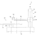
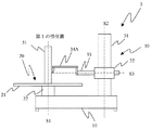
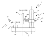
図1は本発明の実施形態に係る真円度測定機の構成を示す図である。本実施形態の真円度測定機1は、図1に示すように、本体10と、この本体10の上面一側寄りに配置され被測定物もしくは検査治具を回転駆動させる被測定物回転機構20と、本体10の上面他側寄りに配置され被測定物もしくは検査治具の外表面位置を検出する位置検出機構30とを備えている。なお、本体10の上面での径方向をR方向、本体10の上面に垂直な方向をZ方向とする。
FIG. 1 is a diagram showing a configuration of a roundness measuring machine according to an embodiment of the present invention. As shown in FIG. 1, the
被測定物回転機構20は、本体10に回転駆動機構22を介してテーブル回転軸S1を中心に回転可能に設けられ、被測定物もしくは検査治具が載置されるテーブル21を備えている。なお、テーブル21には、該テーブル21の水平面を調整する調整つまみ(不図示)が設けられており、被測定物もしくは検査治具の軸心と回転体のテーブル回転軸S1を一致させることができるようになっている。
The measured
位置検出機構30は、本体10に略垂直(Z軸と略平行)に立設された直方体形状を有するコラム31と、このコラム31の検出器案内方向軸線S2に沿って昇降可能に設けられたスライダ32と、このスライダ32にR方向のアーム軸S3に沿って摺動可能に設けられたアーム33と、このアーム33に対して着脱自在な検出器ホルダ34を介して取り付けられた検出器35とを備えている。
The
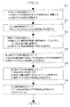
次に、このように構成された本実施形態の真円度測定機の測定精度検定方法について、コラムの平行度検定及びアームの直角度検定の処理の流れを説明する。 Next, regarding the measurement accuracy verification method of the roundness measuring machine of this embodiment configured as described above, the flow of processing of column parallelism test and arm squareness test will be described.
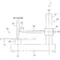
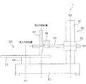
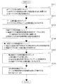
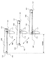
図2は図1の真円度測定機によるコラムの平行度を検定する測定精度検定方法の流れを示すフローチャートであり、図3〜図5は図2の処理における検査治具と、コラム、アーム及び検出器の第1〜第3の配置状態を示す図である。 FIG. 2 is a flowchart showing a flow of a measurement accuracy verification method for verifying the parallelism of a column by the roundness measuring machine of FIG. 1, and FIGS. 3 to 5 are inspection jigs, columns, and arms in the processing of FIG. It is a figure which shows the 1st-3rd arrangement | positioning state of a detector.
コラムの平行度検定:
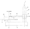
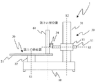
図2に示すように、コラム31の平行度を検定する測定精度検定方法では、ステップS1において、検査者は、検査治具としての円筒マスタ51を載物台の第1の径位置(中心)に載置し、円筒マスタ51の傾きを調整する(円筒マスタ傾き調整ステップ;図3参照)。そして、ステップS2において、検査者は、円筒マスタ51に対するコラム31の傾斜量a0を測定する(コラム傾斜量測定ステップ)。
Column parallelism test:
As shown in FIG. 2, in the measurement accuracy verification method for verifying the parallelism of the
次に、ステップS3において、検査者は、真直マスタ(真直度基準器)61の真直軸をテーブル21に平行、かつ第2の径位置に載置し、真直マスタ61の傾きを調整する(真直マスタ傾き調整ステップ)。 Next, in step S3, the inspector places the straight axis of the straight master (straightness reference device) 61 parallel to the table 21 and at the second radial position, and adjusts the inclination of the straight master 61 (straightness). Master tilt adjustment step).
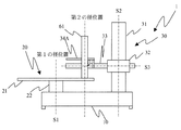
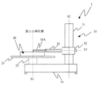
そして、ステップS4において、検査者は、第2の位置を測定できるように、アーム33の先端部から検出器ホルダ34(検出器35を含む)のみを移動し、真直マスタの第1の傾斜量a1を測定する(第1真直マスタ傾斜量測定ステップ;図4参照)。
In step S4, the inspector moves only the detector holder 34 (including the detector 35) from the tip of the
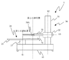
続いて、ステップS5において、検査者は、検出器ホルダ34(検出器35を含む)を元の位置(アーム33の先端部)に戻し、第2の位置を測定できるようにアーム33を移動する。そして、ステップS5にて検査者は、真直マスタ61の第2の傾斜量a2を測定する(第2真直マスタ傾斜量測定ステップ;図5参照)。
Subsequently, in step S5, the inspector returns the detector holder 34 (including the detector 35) to the original position (the tip portion of the arm 33), and moves the
このようにコラム31の傾斜量a0、真直マスタの第1の傾斜量a1及び真直マスタ61の第2の傾斜量a2を測定した後、検査者は、ステップS6において、コラムの真直度軸心の平行度誤差a3を式(1)により算出し(平行度誤差算出ステップ)、処理を終了する。
Thus, after measuring the inclination amount a0 of the
[数1]
a3=(a2−a1)−a0 …(1)
図6は図1の真円度測定機によるアームの直角度を検定する測定精度検定方法の流れを示すフローチャートであり、図7〜図9は図6の処理における検査治具と、コラム、アーム及び検出器の第1〜第3の配置状態を示す図である。
[Equation 1]
a3 = (a2-a1) -a0 (1)
FIG. 6 is a flowchart showing the flow of the measurement accuracy verification method for verifying the perpendicularity of the arm by the roundness measuring machine of FIG. 1, and FIGS. 7 to 9 are the inspection jig, column, and arm in the processing of FIG. It is a figure which shows the 1st-3rd arrangement | positioning state of a detector.
アームの直角度検定:
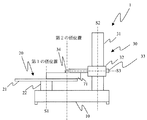
図6に示すように、アーム33の直角度を検定する測定精度検定方法では、ステップS11において、検査者は、検査治具としての水平マスタ71を載物台の第1の径位置(中心)に載置し、水平マスタ71の傾きを調整する(水平マスタ傾き調整ステップ;図7参照)。そして、ステップS12において、検査者は、水平マスタ71に対するアーム33の傾斜量b0を測定する(アーム傾斜量測定ステップ)。
Arm squareness test:
As shown in FIG. 6, in the measurement accuracy verification method for verifying the perpendicularity of the
次に、ステップS13において、検査者は、真直マスタ(真直度基準器)61の真直軸をテーブル21に直交、かつ第2の径位置に載置し、真直マスタ61の傾きを調整する(真直マスタ傾き調整ステップ)。 Next, in step S13, the inspector places the straight axis of the straight master (straightness reference device) 61 perpendicular to the table 21 and at the second radial position, and adjusts the inclination of the straight master 61 (straightness). Master tilt adjustment step).
そして、ステップS14において、検査者は、第2の径位置を測定できるように、アーム33の先端部から検出器ホルダ34(検出器35を含む)のみを移動し、真直マスタの第1の傾斜量b1を測定する(第1真直マスタ傾斜量測定ステップ;図7参照)。
In step S14, the inspector moves only the detector holder 34 (including the detector 35) from the tip of the
続いて、ステップS15において、検査者は、検出器ホルダ34(検出器35を含む)を元の位置(アーム33の先端部)に戻し、第2の位置を測定できるようにアーム33を移動する。そして、ステップS15にて検査者は、真直マスタ61の第2の傾斜量b2を測定する(第2真直マスタ傾斜量測定ステップ;図5参照)。
Subsequently, in step S15, the inspector returns the detector holder 34 (including the detector 35) to the original position (the tip of the arm 33), and moves the
このようにアーム33の傾斜量b0、真直マスタの第1の傾斜量b1及び真直マスタ61の第2の傾斜量b2を測定した後、検査者は、ステップS16において、アームの真直度軸心の直角度誤差b3を式(2)により算出し(直角度誤差算出ステップ)、処理を終了する。
After measuring the inclination amount b0 of the
[数2]
b3=(b2−b1)−b0 …(2)
以上説明したように、従来構成を同様な構成の真円度測定機1を用い、装置を大型化することなく、かつ回転台の回転軸心を基準とした任意の径位置で、コラム31の平行度、アーム33の直角度を実測結果(平行度誤差、直角度誤差)により真円度測定機1の補正量を検定することができる。
[Equation 2]
b3 = (b2-b1) -b0 (2)
As described above, the
なお、本実施形態においては、それぞれ位置を認識するセンサを取り付けると、自動で補正を入れ替えることができる。 In the present embodiment, the correction can be automatically replaced by attaching a sensor for recognizing each position.
また、真直マスタ61の載置位置は、第1の径位置及び第2の径位置の2箇所に限らず、条件を満たせば真直マスタ61の載置位置は任意に設定できる。
Further, the mounting position of the
また、第1の径位置及び第2の径位置のそれぞれ位置を認識するセンサを取り付けることで、自動で真円度測定機1の補正を検定することも可能である。
In addition, it is possible to automatically verify the correction of the
なお、図10ないし図15に示すように、第1の径位置を計測するために、長い検出器ホルダ34A(検出器35を含む)を用いるようにしてもよく、この場合アーム33を短くすることができる。なお、第2の径位置を計測するためには長い検出器ホルダ34Aから検出器ホルダ34に取り替えることになる。
As shown in FIGS. 10 to 15, a
また、図16に示すように、第1の径位置を計測するために、長さ調整式の検出器ホルダ34B(検出器35を含む)を用いるようにしてもよく、この場合アーム33を短くでき、かつ測定位置によっては検出器ホルダを交換しなくてもよい。
In addition, as shown in FIG. 16, a length-
なお、図17に示すように、検出器ホルダ34B(検出器35を含む)の長さを検知する場合、検出器ホルダ34B(検出器35を含む)の可動範囲をストッパ100,101により規制し、さらに検出器ホルダ34B(検出器35を含む)の長さを検知するための光学センサ110,111を設けることにより、光学センサ110,111にて検出器ホルダ34B(検出器35を含む)に設けた遮蔽板120,121を検出して位置(第1及び第2の径位置)を認識するように構成してよい。
As shown in FIG. 17, when the length of the
すなわち、検出器ホルダ34B(検出器35を含む)がストッパ100により位置決めされると光学センサ110が遮蔽板120により遮蔽され検出器ホルダ34B(検出器35を含む)の位置(第1の径位置)が検出でき、同様に、検出器ホルダ34B(検出器35を含む)がストッパ101により位置決めされると光学センサ111が遮蔽板121により遮蔽され検出器ホルダ34B(検出器35を含む)の位置(第2の径位置)が検出できる。
That is, when the
以上、本発明の真円度測定機における測定精度検定方について詳細に説明したが、本発明は、以上の例には限定されず、本発明の要旨を逸脱しない範囲において、各種の改良や変形を行ってもよいのはもちろんである。 As described above, the measurement accuracy verification method in the roundness measuring machine of the present invention has been described in detail. However, the present invention is not limited to the above examples, and various improvements and modifications can be made without departing from the gist of the present invention. Of course, you may also do.
10…本体、20…被測定物回転機構、21…テーブル、21…回転駆動機構、30…位置検出機構、31…コラム、32…スライダ、33…アーム、34…検出器ホルダ、35…検出器
DESCRIPTION OF
Claims (4)
前記回転台の径方向の第1の径位置に載置された円筒マスタの軸心と、前記回転軸心と、が平行になるように前記円筒マスタの傾きを調整する円筒マスタ傾き調整ステップと、 前記検出器を先端部に配置した前記アームの先端位置を前記第1の径位置に対応した第1の測定位置に延出し、前記円筒マスタの表面の少なくとも前記回転軸心方向の2点間にて前記検出器により前記円筒マスタの表面をトレースすることにより前記第1の測定位置での前記コラムの真直度軸心のコラム傾斜量を測定するコラム傾斜量測定ステップと、
前記第1の径位置とは異なる前記回転台の外径側の第2の径位置に載置された真直マスタの軸心と、コラムの移動軸心と、が平行になるように前記真直マスタの傾きを調整する真直マスタ傾き調整ステップと、
前記アームを固定した状態で前記検出器を前記アーム上の前記第2の径位置に対応した第2の測定位置に配置し、前記真直マスタの表面の少なくとも前記回転軸心方向の2点間にて前記検出器により前記真直マスタの表面をトレースすることにより、前記真直マスタの真直度軸心の第1の傾斜量を測定する第1真直マスタ傾斜量測定ステップと、
前記検出器を前記アームの先端に再度配置すると共に前記アームの先端位置を前記第2の測定位置に延出移動し、前記真直マスタの表面の少なくとも前記回転軸心方向の2点間にて前記検出器により前記真直マスタの表面をトレースすることにより、前記真直マスタの真直度軸心の第2の傾斜量を測定する第2真直マスタ傾斜量測定ステップと、
前記コラム傾斜量、前記第1の傾斜量及び前記第2の傾斜量に基づき、前記回転軸心に対する前記第2の測定位置での前記コラムの真直度軸心の平行度誤差を算出する平行度誤差算出ステップと、
を備えたことを特徴とする真円度測定機の測定精度検定方法。 A column that moves in the direction of the rotation axis of the rotation axis of the rotary table on which the work is placed, an arm that moves in the radial direction of the rotation axis, and each section of the workpiece that is detachably attached to the arm In a measuring accuracy verification method of a roundness measuring machine equipped with a detector for measuring roundness,
A cylinder master inclination adjusting step for adjusting the inclination of the cylinder master so that the axis of the cylinder master placed at the first radial position in the radial direction of the turntable and the axis of rotation are parallel; The tip position of the arm with the detector disposed at the tip is extended to a first measurement position corresponding to the first radial position, and at least between two points in the rotational axis direction on the surface of the cylindrical master Measuring the column inclination amount of the straightness axis of the column at the first measurement position by tracing the surface of the cylindrical master with the detector at
The straight master so that the axis of the straight master placed at the second radial position on the outer diameter side of the turntable different from the first radial position is parallel to the axis of movement of the column. Straight master tilt adjustment step to adjust the tilt of
With the arm fixed, the detector is disposed at a second measurement position corresponding to the second radial position on the arm, and at least between two points on the surface of the straight master in the direction of the rotation axis. A first straight master inclination amount measuring step for measuring a first inclination amount of the straightness axis of the straight master by tracing the surface of the straight master by the detector;
The detector is repositioned at the tip of the arm and the tip position of the arm is extended to the second measurement position, and the surface of the straight master is at least between two points in the rotational axis direction. A second straight master tilt amount measuring step for measuring a second tilt amount of the straightness axis of the straight master by tracing the surface of the straight master with a detector;
Parallelism for calculating a parallelism error of the straightness axis of the column at the second measurement position with respect to the rotation axis based on the column inclination amount, the first inclination amount, and the second inclination amount An error calculating step;
A measuring accuracy verification method for a roundness measuring machine, comprising:
(平行度誤差)=(第2の傾斜量)−(第1の傾斜量)−(コラム傾斜量)
により前記平行度誤差を算出することを特徴とする請求項1に記載の真円度測定機の測定精度検定方法。 The parallelism error calculating step includes:
(Parallelity error) = (second tilt amount) − (first tilt amount) − (column tilt amount)
The method according to claim 1, wherein the parallelism error is calculated by:
前記回転台の径方向の第1の径位置に載置された平面マスタの軸心と、前記回転軸心と、が直交するように前記平面マスタの傾きを調整する平面マスタ傾き調整ステップと、
前記検出器を先端部に配置した前記アームの先端位置を前記第1の径位置に対応した第1の測定位置に延出し、前記平面マスタの表面の少なくとも前記回転軸心に直交する方向の2点間にて前記検出器により前記平面マスタの表面をトレースすることにより前記アームの真直度軸心のアーム傾斜量を測定するアーム傾斜量測定ステップと、
前記第1の径位置とは異なる前記回転台の外径側の第2の径位置に載置された真直マスタの軸心と、アームの移動軸心と、が平行になるように前記真直マスタの傾きを調整する真直マスタ傾き調整ステップと、
前記アームを固定した状態で前記検出器を前記アーム上の前記第2の径位置に対応した第2の測定位置に配置し、前記真直マスタの表面の少なくとも前記回転軸心方向に直交する2点間にて前記検出器により前記真直マスタの表面をトレースすることにより、前記真直マスタの真直度軸心の第1の傾斜量を測定する第1傾斜量測定ステップと、
前記検出器を前記アームの先端に再度配置すると共に前記アームの先端位置を前記第2の測定位置に延出移動し、前記真直マスタの表面の少なくとも前記回転軸心方向に直交する2点間にて前記検出器により前記真直マスタの表面をトレースすることにより、前記真直マスタの真直度軸心の第2の傾斜量を測定する第2傾斜量測定ステップと、
前記アーム傾斜量、前記第1の傾斜量及び前記第2の傾斜量に基づき、前記回転軸心に対する前記第2の測定位置での前記アームの真直度軸心の直角度誤差を算出する直角度誤差算出ステップと、
を備えたことを特徴とする真円度測定機の測定精度検定方法。 A column that moves in the direction of the rotation axis of the rotation axis of the rotary table on which the work is placed, an arm that moves in the radial direction of the rotation axis, and each section of the workpiece that is detachably attached to the arm In a measuring accuracy verification method of a roundness measuring machine equipped with a detector for measuring roundness,
A plane master inclination adjusting step for adjusting the inclination of the plane master so that the axis of the plane master placed at the first radial position in the radial direction of the turntable and the axis of rotation are orthogonal;
The position of the tip of the arm having the detector disposed at the tip is extended to a first measurement position corresponding to the first radial position, and 2 in a direction perpendicular to at least the rotational axis of the surface of the planar master. An arm inclination amount measuring step for measuring an arm inclination amount of the straightness axis of the arm by tracing the surface of the planar master with the detector between points;
The straight master so that the axis of the straight master placed at the second radial position on the outer diameter side of the turntable different from the first radial position is parallel to the axis of movement of the arm. Straight master tilt adjustment step to adjust the tilt of
The detector is placed at a second measurement position corresponding to the second radial position on the arm in a state where the arm is fixed, and at least two points perpendicular to the rotational axis direction of the surface of the straight master A first inclination amount measuring step of measuring a first inclination amount of the straightness axis of the straight master by tracing the surface of the straight master by the detector in between;
The detector is repositioned at the tip of the arm, and the tip position of the arm is extended to the second measurement position, and between at least two points on the surface of the straight master perpendicular to the rotational axis direction. A second inclination amount measuring step of measuring a second inclination amount of the straightness axis of the straight master by tracing the surface of the straight master by the detector.
Squareness for calculating the squareness error of the straightness axis of the arm at the second measurement position with respect to the rotation axis based on the arm inclination amount, the first inclination amount, and the second inclination amount An error calculating step;
A measuring accuracy verification method for a roundness measuring machine, comprising:
(直角度誤差)=(第2の傾斜量)−(第1の傾斜量)−(アーム傾斜量)
により前記直角度誤差を算出することを特徴とする請求項3に記載の真円度測定機の測定精度検定方法。 The squareness error calculating step includes:
(Square angle error) = (second inclination amount) − (first inclination amount) − (arm inclination amount)
4. The method for verifying the accuracy of roundness measuring machine according to claim 3, wherein the squareness error is calculated by:
Priority Applications (1)
| Application Number | Priority Date | Filing Date | Title |
|---|---|---|---|
| JP2009275748A JP5565610B2 (en) | 2009-12-03 | 2009-12-03 | Measurement accuracy verification method of roundness measuring machine |
Applications Claiming Priority (1)
| Application Number | Priority Date | Filing Date | Title |
|---|---|---|---|
| JP2009275748A JP5565610B2 (en) | 2009-12-03 | 2009-12-03 | Measurement accuracy verification method of roundness measuring machine |
Publications (2)
| Publication Number | Publication Date |
|---|---|
| JP2011117841A true JP2011117841A (en) | 2011-06-16 |
| JP5565610B2 JP5565610B2 (en) | 2014-08-06 |
Family
ID=44283347
Family Applications (1)
| Application Number | Title | Priority Date | Filing Date |
|---|---|---|---|
| JP2009275748A Expired - Fee Related JP5565610B2 (en) | 2009-12-03 | 2009-12-03 | Measurement accuracy verification method of roundness measuring machine |
Country Status (1)
| Country | Link |
|---|---|
| JP (1) | JP5565610B2 (en) |
Families Citing this family (1)
| Publication number | Priority date | Publication date | Assignee | Title |
|---|---|---|---|---|
| CN109164726A (en) * | 2018-07-19 | 2019-01-08 | 中国科学院长春光学精密机械与物理研究所 | Torque motor drives turntable parameter test device |
Citations (2)
| Publication number | Priority date | Publication date | Assignee | Title |
|---|---|---|---|---|
| JPH05196411A (en) * | 1992-01-21 | 1993-08-06 | Tokyo Seimitsu Co Ltd | Method for measuring parallelism error between rotary axis center and straightness of roundness measuring machine |
| JP2004163358A (en) * | 2002-11-15 | 2004-06-10 | Mitsutoyo Corp | Relative inclined amount measuring method of roundness finder, measurement value correcting method, inspection tool,and manufacturing method thereof |
-
2009
- 2009-12-03 JP JP2009275748A patent/JP5565610B2/en not_active Expired - Fee Related
Patent Citations (2)
| Publication number | Priority date | Publication date | Assignee | Title |
|---|---|---|---|---|
| JPH05196411A (en) * | 1992-01-21 | 1993-08-06 | Tokyo Seimitsu Co Ltd | Method for measuring parallelism error between rotary axis center and straightness of roundness measuring machine |
| JP2004163358A (en) * | 2002-11-15 | 2004-06-10 | Mitsutoyo Corp | Relative inclined amount measuring method of roundness finder, measurement value correcting method, inspection tool,and manufacturing method thereof |
Also Published As
| Publication number | Publication date |
|---|---|
| JP5565610B2 (en) | 2014-08-06 |
Similar Documents
| Publication | Publication Date | Title |
|---|---|---|
| JP4968600B1 (en) | Roundness measuring device and method of correcting misalignment | |
| JP5277033B2 (en) | Correction ball diameter calculation method and shape measuring apparatus | |
| US7712224B2 (en) | Validating the error map of CMM using calibrated probe | |
| CN107883871A (en) | A kind of worm measuring method | |
| US8504316B2 (en) | Form measuring instrument, and calibration method and calibration program therefor | |
| JP5337955B2 (en) | Shape measuring apparatus, shape measuring method, and program | |
| JP2006231509A (en) | Method for measuring program control type machine tool | |
| JP6671011B2 (en) | Roundness measuring device | |
| JP5297906B2 (en) | Image probe calibration method and shape measuring machine | |
| CN102636137A (en) | REVO (Resident Encrypted Variable Output) measuring head position posture calibrating method in joint arm type coordinate measuring machine | |
| JP6657552B2 (en) | Flatness measurement method | |
| TWI405057B (en) | Dynamic path detection method and device for five - axis machine | |
| JP2015068740A (en) | Roundness measuring device | |
| CN204188158U (en) | A kind of flatness checking device of variable detection position | |
| CN104344803A (en) | Flatness detecting device with variable detecting position | |
| JP6824798B2 (en) | Inner diameter measuring device and inner diameter measuring method using it | |
| JP2015064235A (en) | Roundness measuring machine | |
| CN108534676B (en) | A method for checking the spatial error in the measurement space of a coordinate measuring machine | |
| JP5716427B2 (en) | Roundness measuring device and method of correcting misalignment | |
| CN105043280B (en) | A kind of centre of gyration measurement method for distance | |
| JP7201208B2 (en) | Calibration gauge and calibration method | |
| JP5565610B2 (en) | Measurement accuracy verification method of roundness measuring machine | |
| CN107063052A (en) | A kind of space endoporus axis angle detection device | |
| JP6893850B2 (en) | Rolling bearing squareness measuring device and rolling bearing squareness measuring method | |
| JP5742078B2 (en) | Roundness measuring device, misalignment correction method, and misalignment calculation method |
Legal Events
| Date | Code | Title | Description |
|---|---|---|---|
| A621 | Written request for application examination |
Free format text: JAPANESE INTERMEDIATE CODE: A621 Effective date: 20121105 |
|
| A977 | Report on retrieval |
Free format text: JAPANESE INTERMEDIATE CODE: A971007 Effective date: 20130510 |
|
| A131 | Notification of reasons for refusal |
Free format text: JAPANESE INTERMEDIATE CODE: A131 Effective date: 20130701 |
|
| A521 | Request for written amendment filed |
Free format text: JAPANESE INTERMEDIATE CODE: A523 Effective date: 20130829 |
|
| TRDD | Decision of grant or rejection written | ||
| A01 | Written decision to grant a patent or to grant a registration (utility model) |
Free format text: JAPANESE INTERMEDIATE CODE: A01 Effective date: 20140522 |
|
| A61 | First payment of annual fees (during grant procedure) |
Free format text: JAPANESE INTERMEDIATE CODE: A61 Effective date: 20140604 |
|
| R150 | Certificate of patent or registration of utility model |
Ref document number: 5565610 Country of ref document: JP Free format text: JAPANESE INTERMEDIATE CODE: R150 |
|
| R250 | Receipt of annual fees |
Free format text: JAPANESE INTERMEDIATE CODE: R250 |
|
| R250 | Receipt of annual fees |
Free format text: JAPANESE INTERMEDIATE CODE: R250 |
|
| R250 | Receipt of annual fees |
Free format text: JAPANESE INTERMEDIATE CODE: R250 |
|
| R250 | Receipt of annual fees |
Free format text: JAPANESE INTERMEDIATE CODE: R250 |
|
| R250 | Receipt of annual fees |
Free format text: JAPANESE INTERMEDIATE CODE: R250 |
|
| R250 | Receipt of annual fees |
Free format text: JAPANESE INTERMEDIATE CODE: R250 |
|
| LAPS | Cancellation because of no payment of annual fees |