JP2011111802A - Connecting structure of girder bridge - Google Patents
Connecting structure of girder bridge Download PDFInfo
- Publication number
- JP2011111802A JP2011111802A JP2009269141A JP2009269141A JP2011111802A JP 2011111802 A JP2011111802 A JP 2011111802A JP 2009269141 A JP2009269141 A JP 2009269141A JP 2009269141 A JP2009269141 A JP 2009269141A JP 2011111802 A JP2011111802 A JP 2011111802A
- Authority
- JP
- Japan
- Prior art keywords
- slab
- main
- girder
- superstructure
- connecting material
- Prior art date
- Legal status (The legal status is an assumption and is not a legal conclusion. Google has not performed a legal analysis and makes no representation as to the accuracy of the status listed.)
- Granted
Links
- 239000000463 material Substances 0.000 claims abstract description 96
- 239000003351 stiffener Substances 0.000 claims description 87
- 238000005452 bending Methods 0.000 claims description 21
- 239000004567 concrete Substances 0.000 claims description 20
- 229910000831 Steel Inorganic materials 0.000 description 27
- 239000010959 steel Substances 0.000 description 27
- 230000010354 integration Effects 0.000 description 9
- 230000001965 increasing effect Effects 0.000 description 7
- 238000007788 roughening Methods 0.000 description 7
- 239000004570 mortar (masonry) Substances 0.000 description 6
- 238000012986 modification Methods 0.000 description 5
- 230000004048 modification Effects 0.000 description 5
- 210000001015 abdomen Anatomy 0.000 description 2
- 230000005540 biological transmission Effects 0.000 description 2
- 238000010586 diagram Methods 0.000 description 2
- 230000000694 effects Effects 0.000 description 2
- 230000007613 environmental effect Effects 0.000 description 2
- 238000003780 insertion Methods 0.000 description 2
- 230000037431 insertion Effects 0.000 description 2
- 238000010276 construction Methods 0.000 description 1
- 238000009434 installation Methods 0.000 description 1
- 238000004519 manufacturing process Methods 0.000 description 1
- 230000002265 prevention Effects 0.000 description 1
- 230000001902 propagating effect Effects 0.000 description 1
- 239000011150 reinforced concrete Substances 0.000 description 1
- 230000003014 reinforcing effect Effects 0.000 description 1
- 238000005096 rolling process Methods 0.000 description 1
- 238000007711 solidification Methods 0.000 description 1
- 230000008023 solidification Effects 0.000 description 1
- 230000001629 suppression Effects 0.000 description 1
- 239000002023 wood Substances 0.000 description 1
Images
Landscapes
- Bridges Or Land Bridges (AREA)
Abstract
【課題】 複数の上部工本体が並列に架設されていることに起因する橋台や橋脚のロッキング振動を防止する。
【解決手段】本発明に係る桁橋の連結構造1は、鉄道用桁橋13のRC上部工本体6,6を連結材12を介して相互に連結してある。連結材12は、2つのRC上部工本体6,6の一方に属する主桁3と他方に属し該主桁に対向する主桁3の間に橋軸直交方向に沿って配置してあり、該連結材の各端を、2つの主桁3,3のウェブにそれぞれ固着するとともに、該連結材の上面を、2つのRC上部工本体6,6の一方に属するスラブ5と他方に属し該スラブに隣り合うスラブ5にそれぞれ固着してある。
【選択図】 図1
PROBLEM TO BE SOLVED: To prevent rocking vibration of an abutment or a pier caused by a plurality of superstructure bodies being installed in parallel.
In a girder bridge connection structure according to the present invention, RC superstructure main bodies (6, 6) of a railway girder bridge (13) are connected to each other via a connecting material (12). The connecting member 12 is disposed along the direction perpendicular to the bridge axis between the main girder 3 belonging to one of the two RC superstructure main bodies 6 and 6 and the main girder 3 belonging to the other and opposed to the main girder, Each end of the connecting material is fixed to the webs of the two main girders 3 and 3, and the upper surface of the connecting material is attached to the slab 5 belonging to one of the two RC superstructure bodies 6 and 6 and to the other of the slab. Are fixed to slabs 5 adjacent to each other.
[Selection] Figure 1
Description
本発明は、主として鉄道用の桁橋に適用される桁橋の連結構造に関する。 The present invention relates to a girder bridge connection structure mainly applied to a railway girder bridge.
鉄道用の橋梁に採用される構造形式には、ラーメン高架橋や桁橋があるが、これらのうち、鉄道用の桁橋は、橋脚や橋台に主桁を架け渡して該主桁を横桁で橋軸直交方向に相互連結するとともに該主桁及び横桁の上にスラブを載せ、該スラブ上に列車軌道を敷設してなる。 The structural types adopted for railway bridges include ramen viaducts and girder bridges. Of these, girder bridges for railways span the main girder on the bridge piers and abutments, and the main girder is a horizontal girder. They are interconnected in the direction orthogonal to the bridge axis, and a slab is placed on the main girder and the cross girder, and a train track is laid on the slab.
かかる桁橋は、列車運用の面から見ると、複数の軌道を敷設して該複数の軌道を複線として運用する、単一の軌道を敷設して単線として運用する、複数の軌道を敷設して単線並列として運用するなどさまざまであるが、このような運用上の違いとは別に、同一スラブ上に軌道を敷設するのか、相異なる別のスラブ上に軌道を敷設するのかという構造上の違いがある。 From the viewpoint of train operation, such a girder bridge is constructed by laying a plurality of tracks, laying a plurality of tracks and operating the plurality of tracks as a double track, laying a single track and operating as a single track, Apart from these operational differences, there are structural differences such as whether tracks are laid on the same slab or different slabs. is there.
すなわち、一般的には、主桁、横桁及びスラブからなる上部工本体を橋台や橋脚上に架け渡し、該スラブ上に単一の軌道を敷設して単線として運用したり、複数の軌道を敷設して複線、複々線あるいは単線並列として運用することが多いが、周辺地形その他の事情により、上述した上部工本体を複数並列させて橋台や橋脚に架け渡すことも少なくない。 In other words, in general, the upper work body consisting of main girder, cross girder and slab is bridged on the abutment or pier, and a single track is laid on the slab to operate as a single track, or multiple tracks can be operated. In many cases, it is installed and operated as a double track, multiple track, or single track parallel. However, due to surrounding terrain and other circumstances, it is often the case that a plurality of superstructure bodies described above are juxtaposed and bridged over an abutment or pier.
前者の場合、軌道上を走行する列車の荷重は、同一の上部工本体を介して橋脚や橋台に作用するため、列車の走行荷重は、橋軸直交方向に沿って概ね均等に橋台や橋脚の頂部に作用し、あるいは均等とは言えずとも、大きな偏心がない状態で橋台や橋脚の頂部に作用する。 In the former case, the load of the train traveling on the track acts on the piers and abutments via the same superstructure body, so the train load is approximately evenly distributed along the direction perpendicular to the bridge axis. It acts on the top or on the top of the abutment or pier with no large eccentricity, even if not equally.
しかしながら、後者の場合、すなわち、複数の上部工本体が並列に架け渡されている場合、列車の走行荷重は、上部工本体の架設位置に応じて橋台や橋脚に作用し、橋台や橋脚は、列車からの走行荷重を偏心鉛直荷重として受けることとなる。 However, in the latter case, that is, when a plurality of superstructure main bodies are bridged in parallel, the traveling load of the train acts on the abutment and the pier according to the installation position of the superstructure main body, The running load from the train is received as an eccentric vertical load.
そのため、橋台や橋脚が橋軸廻りにロッキング振動を起こするとともに、該ロッキング振動による地盤振動が周辺に伝播し、不測の環境被害を招く懸念があった。 For this reason, the abutment and the pier cause rocking vibration around the bridge shaft, and the ground vibration due to the rocking vibration propagates to the surrounding area, which may cause unexpected environmental damage.
また、新幹線等の鉄道車両が桁橋を通過する際、列車周辺の空気の乱れによる空力音、列車の駆動音、軌道の振動による転動音といった様々な音が発生するが、かかる音は、近隣に伝播して騒音被害を招く原因となる。 In addition, when a railway vehicle such as the Shinkansen passes through a girder bridge, various sounds such as aerodynamic sound due to turbulence of air around the train, train driving sound, rolling sound due to track vibration are generated. Propagating to the neighborhood and causing noise damage.
これらのうち、桁橋を構成する構造部材に伝達した振動に起因する音は構造物音と呼ばれており、鋼製の鉄道桁橋については従来からさまざまな騒音対策がとられてきたが、昨今の新幹線の速度向上に伴い、鋼製の桁橋よりも構造物音が小さいとされてきた鉄筋コンクリート製(以下、RC)の桁橋についても、騒音被害の拡大が懸念されるようになってきた。 Of these, the sound caused by vibrations transmitted to the structural members that make up the girder bridge is called structural sound, and various noise countermeasures have been taken for steel girder bridges. As the speed of the Shinkansen increases, reinforced concrete (hereinafter referred to as RC) girder bridges, which have been thought to have lower structural noise than steel girder bridges, are becoming increasingly concerned about noise damage.
かかる状況下、本出願人の研究により、RC桁橋においては、中間スラブや張出スラブあるいは主桁が構造物音の主たる発生源であり、かかる構造部材の板振動が騒音の原因となることがわかってきたが、どのような対策を施せばよいのか、有効かつ合理的な対策が未だ提案されていないのが現状であり、周辺への騒音低減を含めた環境対策として、RC桁橋の構造物音対策が急務となっていた。 Under such circumstances, according to the applicant's research, in RC girder bridges, intermediate slabs, overhang slabs or main girders are the main sources of structural sound, and plate vibrations of such structural members may cause noise. Although it has been understood, no effective and rational measures have yet been proposed as to what measures should be taken, and the structure of the RC girder bridge is an environmental measure including noise reduction to the surroundings. Noise countermeasures were urgently needed.
本発明は、上述した事情を考慮してなされたもので、複数の上部工本体が並列に架設されていることに起因する橋台や橋脚のロッキング振動を防止することが可能な桁橋の連結構造を提供することを目的とする。 The present invention has been made in consideration of the above-described circumstances, and is a girder bridge connection structure capable of preventing rocking vibration of an abutment and a pier caused by a plurality of superstructure bodies being installed in parallel. The purpose is to provide.
また、本発明は、RC桁橋から発生する構造物音を低減可能な桁橋の連結構造を提供することを目的とする。 Moreover, an object of this invention is to provide the connection structure of the girder bridge which can reduce the structure sound generated from RC girder bridge.
上記目的を達成するため、本発明に係る桁橋の連結構造は請求項1に記載したように、互いに平行に配置された複数の主桁、該複数の主桁をそれらの直交方向に沿って相互連結する横桁及び前記複数の主桁及び前記横桁で支持されたスラブを備えたRC上部工本体を橋脚又は橋台の頂部に複数組並列に架け渡してなる桁橋の連結構造において、
前記各RC上部工本体のうち、互いに隣り合う2つのRC上部工本体を所定の連結材を介して相互に連結することにより、該2つのRC上部工本体を一体化したものである。
In order to achieve the above object, a connecting structure of girder bridges according to the present invention includes a plurality of main girders arranged in parallel with each other, and the plurality of main girders along their orthogonal directions. In the girder bridge connecting structure in which a plurality of sets of RC superstructure main bodies having cross beams connected to each other and the plurality of main girders and slabs supported by the cross beams are bridged in parallel on the pier or the top of the abutment,
Among the RC superstructure main bodies, two RC superstructure bodies adjacent to each other are connected to each other via a predetermined connecting material, thereby integrating the two RC superstructure bodies.
また、本発明に係る桁橋の連結構造は、前記2つのRC上部工本体の一方に属する主桁と他方に属し該主桁に対向する主桁の間に前記連結材を配置し、該連結材の各端を前記2つの主桁のウェブにそれぞれ固着するとともに、前記2つのRC上部工本体の一方に属するスラブと他方に属し該スラブに隣り合うスラブに前記連結材の上面をそれぞれ固着したものである。 Further, the girder bridge connecting structure according to the present invention is such that the connecting member is disposed between a main girder belonging to one of the two RC superstructure main bodies and a main girder belonging to the other and opposed to the main girder, Each end of the material is fixed to the web of the two main girders, and the upper surface of the connecting material is fixed to the slab belonging to one of the two RC superstructure main bodies and the slab belonging to the other and adjacent to the slab. Is.
また、本発明に係る桁橋の連結構造は、前記2つのRC上部工本体の一方に属するスラブと他方に属し該スラブに隣り合うスラブとに跨設されるように前記連結材を配置し、該連結材の下面を前記各スラブの上面にそれぞれに固着するとともに、前記連結材の各端を前記各スラブの上面に設けられた路盤コンクリートの側面にそれぞれ固着したものである。 Further, the girder bridge connection structure according to the present invention is arranged such that the connecting material is straddled across the slab belonging to one of the two RC superstructure main bodies and the slab adjacent to the other slab, The lower surface of the connecting material is fixed to the upper surface of each slab, and each end of the connecting material is fixed to the side surface of the roadbed concrete provided on the upper surface of each slab.
また、本発明に係る桁橋の連結構造は、前記各RC上部工本体のうち、同一のRC上部工本体に属する2つの主桁の間に補剛材をそれぞれ配置し、該各補剛材の上面を前記スラブの下面に固着することで前記スラブの面外曲げ剛性を補剛するとともに、各端を前記主桁のウェブにそれぞれ固着することで該ウェブの面外曲げ剛性を補剛したものである。 Moreover, the connection structure of the girder bridge which concerns on this invention arrange | positions a stiffener between two main girders which belong to the same RC superstructure main body among said RC superstructure main bodies, respectively, and each said stiffener By fixing the upper surface of the slab to the lower surface of the slab, the out-of-plane bending rigidity of the slab was stiffened, and by fixing each end to the web of the main girder, the out-of-plane bending rigidity of the web was stiffened. Is.
また、本発明に係る桁橋の連結構造は、前記連結材及び前記各補剛材を橋軸直交方向に沿った共通軸線上にそれぞれ配置し、該連結材及び各補剛材と前記各ウェブに貫通ボルトを挿通して締め付けることにより、前記連結材及び前記各補剛材を相互に連結したものである。 Further, in the girder bridge connection structure according to the present invention, the connecting material and the stiffeners are respectively arranged on a common axis along a direction perpendicular to the bridge axis, and the connecting material, the stiffeners, and the webs are arranged. The connecting material and the stiffeners are connected to each other by inserting through bolts and tightening them.
また、本発明に係る桁橋の連結構造は、前記横桁の配置スパン長をL1、前記主桁の長さをL2としたとき、
L1=L2/N
N;1,2,3・・・
の場合に、前記主桁の端部から、
n・(L2/2・N)
n;1,3,5・・・
の位置に前記連結材及び前記補剛材を配置したものである。
Moreover, the connection structure of the girder according to the present invention is such that when the horizontal span arrangement span length is L 1 and the main girder length is L 2 ,
L 1 = L 2 / N
N; 1, 2, 3 ...
In the case of, from the end of the main girder,
n · (L 2/2 · N)
n; 1, 3, 5 ...
The connecting material and the stiffening material are arranged at the position of.
本発明においては、橋脚又は橋台の頂部に複数組並列に架け渡されたRC上部工本体のうち、互いに隣り合う2つのRC上部工本体を所定の連結材を介して相互に連結することにより、2つのRC上部工本体を一体化する。 In the present invention, by connecting two RC upper work main bodies adjacent to each other via a predetermined connecting material among the RC upper work main bodies spanned in parallel in plural sets on the top of the pier or abutment, Two RC superstructure main bodies are integrated.
このようにすると、一方のRC上部工本体のスラブ上を走行する車両の荷重は、該RC上部工本体直下の橋脚や橋台に作用するのみならず、連結材を介して他方のRC上部工本体にも伝達され、該他方のRC上部工本体直下の橋脚や橋台に作用する。 If it does in this way, the load of the vehicle which runs on the slab of one RC superstructure main body will not only act on the pier and the abutment right under this RC superstructure main body, but the other RC superstructure main body via a connecting material. And acts on the pier and abutment directly under the other RC superstructure main body.
そのため、荷重伝達は、単一のRC上部工本体に複数の軌道を敷設した場合と概ね同等となり、かくして偏心鉛直荷重に起因する橋軸廻りの橋台や橋脚のロッキング振動を未然に防止することが可能となる。 Therefore, load transmission is almost the same as when multiple tracks are laid on a single RC superstructure main body, thus preventing rocking vibration of the abutment and pier around the bridge shaft due to the eccentric vertical load. It becomes possible.
また、連結材を介した各RC上部工本体の一体化作用により、車両走行に伴う荷重は、特定の主桁に集中することなく分散伝達することとなり、かくしてRC上部工本体の鉛直下方へのたわみを抑えることも可能となる。 Also, due to the integrated action of each RC superstructure main body via the connecting material, the load accompanying the vehicle travel is distributed and transmitted without concentrating on a specific main girder, and thus the RC superstructure main body is vertically lowered. It is also possible to suppress the deflection.
連結材は、互いに隣り合う2つのRC上部工本体での車両走行で生じる鉛直荷重が橋脚や橋台に実質的にロッキング振動を生じないように該2つのRC上部工本体が一体化されるのであれば、その構成は任意であって、例えばH形鋼、I形鋼、鋼板等で構成することが可能である。 As for the connecting material, the two RC superstructure main bodies are integrated so that the vertical load generated by the vehicle traveling on the two RC superstructure bodies adjacent to each other does not substantially cause rocking vibration on the pier or the abutment. For example, the structure is arbitrary, for example, it can be comprised with H-section steel, I-section steel, a steel plate, etc.
また、連結材をどのように配置するかも任意であり、例えば、2つのRC上部工本体の一方に属する主桁と他方に属し該主桁に対向する主桁の間に連結材を配置し、該連結材の各端を2つの主桁のウェブにそれぞれ固着するとともに、2つのRC上部工本体の一方に属するスラブと他方に属し該スラブに隣り合うスラブに連結材の上面をそれぞれ固着して構成し、又は2つのRC上部工本体の一方に属するスラブと他方に属し該スラブに隣り合うスラブとに跨設されるように連結材を配置し、該連結材の下面を各スラブの上面にそれぞれに固着するとともに、連結材の各端を各スラブの上面に設けられた路盤コンクリートの側面にそれぞれ固着して構成することができる。 Further, how to arrange the connecting material is also arbitrary, for example, connecting the connecting material between the main beam belonging to one of the two RC superstructure main body and the main beam belonging to the other and facing the main beam, Each end of the connecting material is fixed to the web of the two main girders, and the upper surface of the connecting material is fixed to the slab belonging to one of the two RC superstructure main bodies and the slab belonging to the other and adjacent to the slab. The connecting material is arranged so as to extend over the slab belonging to one of the two RC superstructure main bodies and the slab belonging to the other and adjacent to the slab, and the lower surface of the connecting material is placed on the upper surface of each slab. While being fixed to each, each end of the connecting material can be fixed to the side surface of the roadbed concrete provided on the upper surface of each slab.
このようにすると、連結材は、スラブやウェブの面外曲げ剛性を補剛する役割をも果たすこととなり、かくして車両通過時に起こるスラブや主桁のウェブの板振動が抑制され、該スラブやウェブに起因する構造物音を低減することができる。 In this way, the connecting material also plays a role of reinforcing the out-of-plane bending rigidity of the slab and web, thus suppressing the plate vibration of the slab and main girder web that occurs when the vehicle passes through the slab and web. It is possible to reduce the structure sound caused by the noise.
本発明でいう桁橋は、主桁、横桁及びそれらに支持されたスラブを備えたRC上部工本体が橋脚又は橋台の頂部に複数組並列に架け渡されたものをいうが、RC上部工本体は2組に限定されるものではなく、3組以上でもかまわないし、各RC上部工本体の主桁についても2以上であればよい。 The girder bridge in the present invention refers to a structure in which a plurality of RC superstructure main bodies having main girder, cross girder, and slabs supported by them are spanned in parallel on the pier or the top of the abutment. The main body is not limited to two sets, and three or more sets may be used, and the main girder of each RC superstructure main body may be two or more.
また、本発明の桁橋は、大型トラック等の自動車が走行する道路用のRC桁橋にも適用が可能であるが、列車、特に新幹線等の高速列車が走行する鉄道用RC桁橋に適用したならば、列車走行に伴う橋脚や橋台のロッキング振動を未然に防止することが可能になる。 The girder bridge of the present invention can also be applied to RC girder bridges for roads on which automobiles such as large trucks travel. However, it is applicable to RC girder bridges for railways on which high-speed trains such as bullet trains run. If it does so, it becomes possible to prevent the rocking vibration of the pier and the abutment accompanying a train run.
本発明は、隣り合う2つのRC上部工本体を連結材を介して相互に連結して一体化させることを特徴とするものであるが、これに加えて、各RC上部工本体のうち、同一のRC上部工本体に属する2つの主桁の間に補剛材をそれぞれ配置し、該各補剛材の上面をスラブの下面に固着することでスラブの面外曲げ剛性を補剛するとともに、各端を主桁のウェブにそれぞれ固着することで該ウェブの面外曲げ剛性を補剛したならば、各RC上部工本体の全体の面外曲げ剛性が増大するため、連結材のみの場合に比べて、より確実な一体化が可能となる。 The present invention is characterized in that two adjacent RC superstructure main bodies are connected and integrated with each other via a connecting material. In addition, among the RC superstructure main bodies, Stiffeners are placed between the two main girders belonging to the RC superstructure main body, and the upper surface of each stiffener is fixed to the lower surface of the slab to stiffen the out-of-plane bending rigidity of the slab, If the out-of-plane bending rigidity of the web is stiffened by fixing each end to the main girder web, the overall out-of-plane bending rigidity of each RC superstructure main body increases. In comparison, more reliable integration is possible.
また、補剛材は上述した連結材とともに、車両通過時に起こるスラブや主桁のウェブの板振動を抑制し、スラブやウェブに起因する構造物音を低減する役目を果たす。 Further, the stiffener, together with the above-described connecting material, suppresses plate vibration of the slab and the main girder web that occurs when the vehicle passes, and serves to reduce the structure sound caused by the slab and the web.
ここで、連結材及び各補剛材を橋軸直交方向に沿った共通軸線上にそれぞれ配置し、該連結材及び各補剛材と各ウェブに貫通ボルトを挿通して締め付けることにより、連結材及び各補剛材を相互に連結したならば、一体化の程度がさらに高まり、橋脚や橋台のロッキング振動をより確実に低減することが可能となる。 Here, the connecting material and each stiffener are arranged on a common axis along the direction perpendicular to the bridge axis, and the connecting material, each stiffener and each web are inserted and tightened with a through bolt, thereby connecting the connecting material. If the stiffeners are connected to each other, the degree of integration is further increased, and the rocking vibration of the pier or abutment can be more reliably reduced.
また、横桁の配置スパン長をL1、主桁の長さをL2としたとき、
L1=L2/N
N;1,2,3・・・
の場合に、前記主桁の端部から、
n・(L2/2・N)
n;1,3,5・・・
の位置に連結材及び補剛材を配置する構成を採用することができる。
Also, when the horizontal span arrangement span length is L 1 and the main girder length is L 2 ,
L 1 = L 2 / N
N; 1, 2, 3 ...
In the case of, from the end of the main girder,
n · (L 2/2 · N)
n; 1, 3, 5 ...
The structure which arrange | positions a connection material and a stiffening material in the position of can be employ | adopted.
このようにすれば、スラブや主桁ウェブの板振動が取り得る振動モードのうち、比較的低次モードで腹となる箇所を重点的に抑えることができるので、RC上部工本体の一体化によるロッキング振動の防止に加えて、より合理的な防音対策となる可能性が高い。 By doing this, it is possible to focus on the places that become abdomen in the relatively low-order mode among the vibration modes that can be taken by the plate vibration of the slab and main girder web. In addition to preventing rocking vibration, it is likely to be a more rational soundproofing measure.
以下、本発明に係る桁橋の連結構造の実施の形態について、添付図面を参照して説明する。なお、従来技術と実質的に同一の部品等については同一の符号を付してその説明を省略する。 DESCRIPTION OF EMBODIMENTS Hereinafter, embodiments of a girder bridge connection structure according to the present invention will be described with reference to the accompanying drawings. Note that components that are substantially the same as those of the prior art are assigned the same reference numerals, and descriptions thereof are omitted.
(第1実施形態)
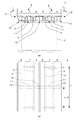
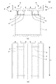
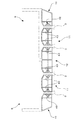
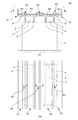
図1は、本実施形態に係る桁橋の連結構造を示した図、図2はその適用対象となる鉄道用桁橋13を示した図である。鉄道用桁橋13は図2でわかるように、橋軸方向に沿って立設された橋脚2の頂部に2本のRC上部工本体6,6を並列に架け渡してなる。
(First embodiment)
FIG. 1 is a diagram showing a connecting structure of girder bridges according to this embodiment, and FIG. 2 is a diagram showing a
RC上部工本体6は、橋軸方向に沿って互いに平行に配置された2本の主桁3と、該主桁をそれらの直交方向に沿って相互連結する横桁4と、主桁3及び横桁4で支持されたスラブ5とを備え、スラブ5上には路盤コンクリート(図示せず)が設けられているとともに、該路盤コンクリート上には列車軌道(図示せず)を敷設してある。
The RC superstructure
本実施形態に係る桁橋の連結構造1は、かかる鉄道用桁橋13に適用されたものであって、図1に示すように、鉄道用桁橋13のRC上部工本体6,6を連結材12を介して相互に連結してある。
The girder
連結材12は、2つのRC上部工本体6,6の一方に属する主桁3と他方に属し該主桁に対向する主桁3の間に橋軸直交方向に沿って配置してあり、該連結材の各端を、2つの主桁3,3のウェブにそれぞれ固着するとともに、該連結材の上面を、2つのRC上部工本体6,6の一方に属するスラブ5と他方に属し該スラブに隣り合うスラブ5にそれぞれ固着してある。
The connecting
ここで、スラブ5は、主桁3,3に挟まれた中間スラブ7とその両側方に延びる張出スラブ8,8とからなり、連結材12は、一方のスラブ5に属する張出スラブ8と他方のスラブ5に属する張出スラブ8にそれぞれ固着してある。
Here, the
一方、各RC上部工本体6のうち、同一のRC上部工本体6に属する2つの主桁3,3の間には、補剛材11をそれぞれ橋軸直交方向に沿ってかつ連結材12と同じ軸線上となるように配置し、該各補剛材の上面を中間スラブ7の下面にそれぞれ固着することで、各スラブ5の面外曲げ剛性を補剛するとともに、補剛材11の各端を主桁3,3のウェブにそれぞれ固着することで、該ウェブの面外曲げ剛性を補剛してある。
On the other hand, among each RC superstructure
さらに、最外位置の主桁3の外側には、補剛材10をそれぞれ橋軸直交方向に沿ってかつ連結材12と同じ軸線上となるように配置するとともに、該補剛材の上面を張出スラブ8の下面にそれぞれ固着することで、各スラブ5の面外曲げ剛性を補剛するとともに、補剛材10の一端を主桁3のウェブにそれぞれ固着することで、該ウェブの面外曲げ剛性を補剛してある。
Further, outside the
横桁4は図1(b)に示すように、その材軸が主桁3に直交する方向(橋軸直交方向)に沿うように、かつ橋軸方向に沿ってスパン長L1ごとに配置してあるが、連結材12は、橋軸方向に沿った横桁4,4の中心位置、すなわち横桁4の材軸からL1/2の位置に配置してあり、補剛材10,11も連結材12と同様、横桁4の材軸からL1/2の位置に配置してある。
なお、本実施形態では、主桁3はL2の桁長を有し、横桁4は、主桁3の各端と、主桁3の桁方向(橋軸方向)に沿ってL1ごとに等間隔で配置されるものとする。すなわち、横桁4が主桁3の両端のみに設けられる場合には、L1=L2であって、横桁4の数は2となり、桁方向に沿った中央位置にも横桁4が設置される場合には、L1=L2/2であって、横桁4の数は3となる。
In this embodiment, the
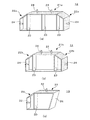
図3(a)は、連結材12を示した全体斜視図である。同図でわかるように、連結材12は、エンドプレート22a,22aをH形鋼21aの各端部にそれぞれ溶着するとともに、該H形鋼の中間位置と端部位置の計3箇所でスチフナ23をH形鋼21aのウェブ両側に溶着してあり、エンドプレート22aは、主桁3と張出スラブ8との取合い箇所に形成されているハンチとその隣接部位にぴったりと当接されるよう、折曲げ形成してある。
FIG. 3A is an overall perspective view showing the connecting
ここで、スチフナ23は、H形鋼21aのウェブの板振動を抑えることで、連結材12自体が構造物音の発生源となるのを防止する役目を果たす。
Here, the
H形鋼21aのフランジ上面には、連結材12による連結工事の際、張出スラブ8の下面に穿孔される穴に挿入可能なアンカー24を突設してあるとともに、張出スラブ8との隙間に充填される固化材との接着性を高めるべく、該フランジ上面に目荒らし処理を施してある。
On the upper surface of the flange of the H-shaped
同様に、エンドプレート22aの折曲げ状側面には、連結工事の際に主桁3の対向側面に穿孔される穴に挿入可能なアンカー24を突設してあるとともに、主桁3との隙間に充填される固化材との接着性を高めるべく、該側面に目荒らし処理を施してある。
Similarly, an
図3(b)は、補剛材11を示した全体斜視図である。同図でわかるように、補剛材11は、エンドプレート22b,22bをH形鋼21bの各端部にそれぞれ溶着するとともに、該H形鋼の端部位置でスチフナ23をH形鋼21bのウェブ両側に溶着してあり、エンドプレート22bは、主桁3と中間スラブ7との取合い箇所に形成されているハンチとその隣接部位にぴったりと当接されるよう、折曲げ形成してある。
FIG. 3B is an overall perspective view showing the
ここで、スチフナ23は、H形鋼21bのウェブの板振動を抑えることで、補剛材11自体が構造物音の発生源となるのを防止する役目を果たす。
Here, the
H形鋼21bのフランジ上面には、連結工事の際、中間スラブ7の下面に穿孔される穴に挿入可能なアンカー24を突設してあるとともに、中間スラブ7との隙間に充填される固化材との接着性を高めるべく、該フランジ上面に目荒らし処理を施してある。
An
同様に、エンドプレート22bの折曲げ状側面には、主桁3の対向側面に穿孔される穴に挿入可能なアンカー24を突設してあるとともに、主桁3との隙間に充填される固化材との接着性を高めるべく、該側面に目荒らし処理を施してある。
Similarly, an
図3(c)は、補剛材10を示した全体斜視図である。同図でわかるように、補剛材10は、H形鋼31の一端にエンドプレート26を斜めに溶着するとともに、他端にエンドプレート29を溶着し、該他端位置でスチフナ30をH形鋼31のウェブ両側に溶着してあり、エンドプレート29は、主桁3と張出スラブ8との取合い箇所に形成されているハンチとその隣接部位にぴったりと当接されるよう、折曲げ形成してある。
FIG. 3C is an overall perspective view showing the
ここで、スチフナ30は、H形鋼31のウェブの板振動を抑えることで、補剛材10自体が構造物音の発生源となるのを防止する役目を果たす。
Here, the
H形鋼31のフランジ上面には、連結工事の際、張出スラブ8の下面に穿孔される穴に挿入可能なアンカー32を突設してあるとともに、張出スラブ8との隙間に充填される固化材との接着性を高めるべく、該フランジ上面に目荒らし処理を施してある。
An
同様に、エンドプレート29の折曲げ状側面には、連結工事の際、主桁3の外側側面に穿孔される穴に挿入可能なアンカー32を突設してあるとともに、主桁3との隙間に充填される固化材との接着性を高めるべく、該側面に目荒らし処理を施してある。
Similarly, an
なお、図3(c)に示した補剛材10は、図1で言えば右側に配置される状態で示したものであるが、左側に配置される状態については、図3(c)と左右対称に現れるため、図面及びその説明を省略する。
Note that the
図2に示した既設の鉄道用RC桁橋13に対して本実施形態に係る桁橋の連結構造1を適用するには、補剛材10,11及び連結材12を工場等で適宜製作して施工現場に搬入する一方、連結材12のアンカー24が挿入される穴を張出スラブ8の下面及び主桁3,3の対向側面に穿孔し、補剛材11のアンカー24が挿入される穴を中間スラブ7の下面及び主桁3,3の対向側面に穿孔し、補剛材10のアンカー32が挿入される穴を張出スラブ8の下面及び主桁3の外側側面に穿孔する。
In order to apply the girder
次に、連結材12のアンカー24を張出スラブ8の下面及び主桁3,3の対向側面に穿孔された穴に挿入し、かかる状態で連結材12と張出スラブ8及び主桁3,3との隙間に無収縮モルタル、極早強モルタル等の固化材を充填する。アンカー24のうち、側方に突出したものについては、着脱自在に構成しておくのがよい。
Next, the
同様に、補剛材11のアンカー24を中間スラブ7の下面及び主桁3,3の対向側面に穿孔された穴に挿入し、かかる状態で補剛材11と中間スラブ7及び主桁3,3との隙間に無収縮モルタル、極早強モルタル等の固化材を充填する。アンカー24のうち、側方に突出したものについては、着脱自在に構成しておくのがよい。
Similarly, the
また、補剛材10のアンカー32を張出スラブ8の下面及び主桁3の外側側面に穿孔された穴に挿入し、かかる状態で補剛材10と張出スラブ8及び主桁3との隙間に上述した固化材を充填する。アンカー32のうち、側方に突出したものについては、着脱自在に構成しておくのがよい。
Further, the
充填された固化材が強度を発現するまでは、必要に応じて適宜支保工を用いればよい。 Until the filled solidified material develops strength, a support work may be used as necessary.
以上説明したように、本実施形態に係る桁橋の連結構造1によれば、2つのRC上部工本体6,6を連結材12を介して相互に連結することで該RC上部工本体を一体化するようにしたので、一方のRC上部工本体6のスラブ5に作用する列車の走行荷重は、連結材12を介して他方のRC上部工本体6にも伝達される。
As described above, according to the connecting
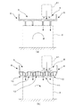
すなわち、並列配置された2本のRC上部工本体6,6を相互に連結しない従来の場合においては、図4(a)に示すように列車41が走行するRC上部工本体6(同図右側)の直下に位置する橋脚2の頂部位置にのみ、列車41の走行荷重が作用し、該橋脚に作用する鉛直荷重が偏心するため、橋脚2には橋軸廻りのロッキング振動が発生する。
That is, in the conventional case where the two RC superstructure
それに対し、本実施形態においては、連結材12による荷重伝達作用により、一方のRC上部工本体6(同図右側)のスラブ5上を走行する列車の荷重は図4(b)に示すように、該RC上部工本体直下に位置する橋脚2の頂部位置のみならず、他方のRC上部工本体6(同図左側)の直下にも伝達される。また、連結材12による荷重伝達作用に加えて、補剛材10及び補剛材11による各RC上部工本体6の剛性増大作用もRC上部工本体6,6の一体化に寄与する。
On the other hand, in this embodiment, the load of the train traveling on the
そのため、橋脚2に作用する鉛直荷重の偏心状況が大幅に緩和され、かくして橋脚2に発生する橋軸廻りのロッキング振動を格段に低減することが可能となる。
As a result, the eccentricity of the vertical load acting on the
また、本実施形態に係る桁橋の連結構造1によれば、連結材12及び補剛材10,11によるRC上部工本体6,6の一体化作用により、車両走行に伴う荷重は、特定の主桁3に集中することなく、多数の主桁3に分散伝達することとなり、かくして橋脚2,2間におけるRC上部工本体6,6の鉛直方向たわみを抑えることも可能となる。
Moreover, according to the
また、本実施形態に係る桁橋の連結構造1によれば、補剛材11は、中間スラブ7の面外曲げ剛性を、補剛材10及び連結材12は、張出スラブ8の面外曲げ剛性をそれぞれ高めるとともに、補剛材10,11及び連結材12の端部が主桁3を構成するウェブの面外曲げ剛性をそれぞれ高めるため、列車通過時に起こる中間スラブ7や張出スラブ8あるいは主桁3を構成するウェブの板振動が抑制されることとなり、かくしてスラブ5や主桁3に起因する構造物音の発生を未然に防止することも可能となる。
Moreover, according to the
また、本実施形態に係る桁橋の連結構造1によれば、連結材12及び補剛材10,11を、橋軸方向に沿った横桁4,4の中心位置、すなわち横桁4の材軸からL1/2の位置に配置するようにしたので、中間スラブ7や主桁3のウェブの板振動が取り得る振動モードのうち、比較的低次モードで腹となる箇所を重点的に抑えることが可能となり、構造物音対策をより合理的に行うことができる。
Moreover, according to the
本実施形態では、補剛材10及び補剛材11を配置することにより、各RC上部工本体6の全体曲げ剛性を高めてRC上部工本体6,6の一体化に寄与させるとともに、構造物音対策も同時に兼ねさせたが、連結材12のみでRC上部工本体6,6の一体化が可能であってかつスラブ5や主桁3の構造物音対策が必要ないのであれば、補剛材10及び補剛材11のうち、いずれかの設置を省略し、又は両方の設置を省略してもかまわない。
In the present embodiment, by arranging the
また、本実施形態では、補剛材10,11及び連結材12を同一の共通軸線上に配置するようにしたが、RC上部工本体6,6の一体化が可能である限り、互いに軸線がずれた位置に配置するようにしてもかまわない。
In the present embodiment, the
一方、補剛材10,11及び連結材12を単に共通軸線上に配置しただけでは一体化の程度が不足する場合、補剛材10,11及び連結材12と主桁3のウェブに貫通ボルトを挿通して締め付けることにより、補剛材10,11及び連結材12を強固に連結して一体化の程度を向上させるようにすることが可能である。
On the other hand, if the degree of integration is insufficient simply by arranging the
図5に示す変形例においては、貫通ボルト42を、同図で言えば右側の補剛材10のエンドプレート29に形成されたボルト孔(図示せず)に挿通してから、右側に位置するRC上部工本体6の右側の主桁3に通し、次いで、補剛材11のエンドプレート22b,22b及びスチフナ23に形成されたボルト孔(図示せず)に挿通し、次いで、左側の主桁3に挿通してから連結材12のエンドプレート22a,22a及びスチフナ23に形成されたボルト孔(図示せず)に挿通し、次いで、左側に位置するRC上部工本体6の右側の主桁3に挿通してから同様にして補剛材11に挿通し、最後に左側の主桁3に挿通して補剛材10に挿通する。
In the modification shown in FIG. 5, the through
このようにして貫通ボルト42を挿通した後、挿通前に予め螺合されあるいは挿通後に螺合されたナット43を締め付けることで、各主桁3が挟み込まれる形で補剛材10,11及び連結材12を貫通ボルト42を介して相互に連結する。
After inserting the through
かかる変形例によれば、補剛材10,11及び連結材12が一体となって、RC上部工本体6,6を強固に一体化させることができる。また、中間スラブ7、張出スラブ8及び各主桁3を構成するウェブの板振動の抑制作用が格段に向上するとともに、補剛材10,11及び連結材12の落下防止事故を未然に防止することも可能となる。さらに、橋軸廻りの主桁3のねじれ剛性が高くなるため、該主桁のねじり振動モードを抑制し、該モードに起因する構造物音を低減することも可能となる。
According to such a modification, the
なお、最も外側の補剛材10,10については適宜省略することができる。
The
(第2実施形態)
次に、第2実施形態について説明する。なお、第1実施形態と実質的に同一の部品等については同一の符号を付してその説明を省略する。
(Second Embodiment)
Next, a second embodiment will be described. Note that components that are substantially the same as those of the first embodiment are denoted by the same reference numerals, and description thereof is omitted.
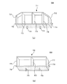
図6は、第2実施形態に係る桁橋の連結構造を示した図である。同図でわかるように、本実施形態に係る桁橋の連結構造51は第1実施形態と同様、鉄道用桁橋13に適用されたものであって、RC上部工本体6,6を連結材59を介して相互に連結してある。
FIG. 6 is a view showing a connecting structure of girder bridges according to the second embodiment. As can be seen in the figure, the girder
連結材59は、2つのRC上部工本体6,6の一方に属するスラブ5と他方に属し該スラブに隣り合うスラブ5とに跨設され、かかる状態でその下面を各スラブ5,5の上面にそれぞれに固着するとともに、その各端をスラブ5,5の上面にそれぞれ設けられた路盤コンクリート52,52の側面にそれぞれ固着してなる。
The connecting
一方、各RC上部工本体6において、路盤コンクリート52と高欄下方に設けられたダクト53との間には補剛材60をそれぞれ配置してあるとともに、該補剛材の一端を路盤コンクリート52の反対側側面に、他端をダクト53の側面にそれぞれ固着してあり、かかる構成によってスラブ5の面外曲げ剛性を補剛し、RC上部工本体6全体の曲げ剛性を高めてRC上部工本体6,6の一体化に寄与させることができるとともに、スラブ5の板振動を抑えることにより、構造物音の発生も低減可能な構成となっている。
On the other hand, in each RC superstructure
図7(a)は、連結材59を示した全体斜視図である。同図でわかるように、連結材59は、エンドプレート72,72をH形鋼71の各端部にそれぞれ溶着するとともに、該H形鋼の中間位置と端部位置の計3箇所でスチフナ73をウェブ両側に溶着してあり、H形鋼71は、曲げ剛性を大きくするために十分な高さを確保するとともに、エンドプレート72は、列車設計側から要求される建築限界に支障がないよう、折曲げ形成してある。
FIG. 7A is an overall perspective view showing the connecting
ここで、スチフナ73は、H形鋼71のウェブの板振動を抑えることで、連結材59自体が構造物音の発生源となるのを防止する役目を果たす。
Here, the
H形鋼71のフランジ下面には、連結材59による連結工事の際、スラブ5の上面に穿孔される穴に挿入可能なアンカー74を突設してあるとともに、スラブ5との隙間に充填される固化材との接着性を高めるべく、該フランジ下面に目荒らし処理を施してある。
On the lower surface of the flange of the H-shaped
同様に、エンドプレート72の折曲げ状側面には、連結工事の際、路盤コンクリート52の側面に穿孔される穴に挿入可能なアンカー74を突設してあるとともに、路盤コンクリート52との隙間に充填される固化材との接着性を高めるべく、該折曲げ状側面に目荒らし処理を施してある。
Similarly, on the bent side surface of the
図7(b)は、補剛材60を示した全体斜視図である。同図でわかるように、補剛材60は、H形鋼75の各端部にエンドプレート77,77をそれぞれ溶着するとともに、該H形鋼の中間位置でスチフナ80をウェブ両側に溶着してある。
FIG. 7B is an overall perspective view showing the
ここで、スチフナ80は、H形鋼75のウェブの板振動を抑えることで、補剛材60自体が構造物音の発生源となるのを防止する役目を果たす。
Here, the
H形鋼75のフランジ下面には、スラブ5の上面のうち、路盤コンクリート52とダクト53の間に拡がっていて部分に穿孔される穴に挿入可能なアンカー79を突設してあるとともに、該部分との隙間に充填される固化材との接着性を高めるべく、該フランジ下面に目荒らし処理を施してある。
On the lower surface of the flange of the H-shaped
同様に、エンドプレート77の側面には、連結工事の際、路盤コンクリート52の外側側面やダクト53の側面に穿孔される穴に挿入可能なアンカー79を突設してあるとともに、路盤コンクリート52やダクト53との隙間に充填される固化材との接着性を高めるべく、該側面に目荒らし処理を施してある。
Similarly, on the side surface of the
図2に示した既設のRC桁橋13に対して本実施形態に係る桁橋の連結構造51を適用するには、連結材59及び補剛材60を工場等で適宜製作して施工現場に搬入する一方、連結材59のアンカー74が挿入される穴をスラブ5,5の上面及び路盤コンクリート52,52の側面にそれぞれ穿孔するとともに、補剛材60のアンカー79が挿入される穴をスラブ5の上面、路盤コンクリート52の側面及びダクト53の側面に穿孔する。
In order to apply the girder
次に、連結材59のアンカー74をスラブ5の上面及び路盤コンクリート52,52の対向側面に穿孔された穴に挿入し、かかる状態で連結材59とスラブ5及び路盤コンクリート52,52との隙間に無収縮モルタル、極早強モルタル等の固化材を充填する。アンカー74のうち、側方に突出したものについては、着脱自在に構成しておくのがよい。
Next, the
同様に、補剛材60のアンカー79をスラブ5の上面、路盤コンクリート52の外側側面及びダクト53の側面に穿孔された穴に挿入し、かかる状態で補剛材60とスラブ5との隙間、路盤コンクリート52及びダクト53との隙間に上述した固化材をそれぞれ充填する。アンカー79のうち、側方に突出したものについては、着脱自在に構成しておくのがよい。
Similarly, the
以上説明したように、本実施形態に係る桁橋の連結構造51によれば、2つのRC上部工本体6,6を連結材59を介して相互に連結することで該RC上部工本体を一体化するようにしたので、図4を用いて説明した第1実施形態と同様、一方のRC上部工本体6のスラブ5に作用する列車の走行荷重は、連結材59を介して他方のRC上部工本体6にも伝達される。
As described above, according to the
そのため、橋脚2に作用する鉛直荷重の偏心状況が大幅に緩和され、かくして橋脚2に発生する橋軸廻りのロッキング振動を格段に低減することが可能となる。
As a result, the eccentricity of the vertical load acting on the
また、本実施形態に係る桁橋の連結構造51によれば、連結材59及び補剛材60,60によるRC上部工本体6,6の一体化作用により、車両走行に伴う荷重は、特定の主桁3に集中することなく、多数の主桁3に分散伝達することとなり、かくして橋脚2,2間におけるRC上部工本体6,6の鉛直たわみを抑えることも可能となる。
Moreover, according to the
また、本実施形態に係る桁橋の連結構造51によれば、連結材59及び補剛材60,60は、路盤コンクリート52,52と相俟って、スラブ5,5の面外曲げ剛性を高めるため、列車通過時に起こるスラブ5の板振動が抑制されることとなり、かくしてスラブ5に起因する構造物音の発生を未然に防止することも可能となる。
Moreover, according to the
本実施形態では、補剛材60を配置することにより、各RC上部工本体6の全体曲げ剛性を高めてRC上部工本体6,6の一体化に寄与させるとともに、構造物音対策も同時に兼ねさせたが、連結材59のみでRC上部工本体6,6の一体化が可能であってかつスラブ5の構造物音対策が必要ないのであれば、補剛材60を省略してもかまわない。
In the present embodiment, by arranging the
また、本実施形態では、連結材59及び補剛材60を同一の共通軸線上に配置するようにしたが、RC上部工本体6,6の一体化が可能である限り、互いに軸線がずれた位置に配置するようにしてもかまわない。
In the present embodiment, the connecting
また、本実施形態では特に言及しなかったが、連結材59を第1実施形態で説明した連結材12と併用することが可能であり、かかる変形例によれば、RC上部工本体6,6をさらに確実に一体化することが可能となる。
Although not particularly mentioned in the present embodiment, the connecting
また、補剛材60を第1実施形態で説明した補剛材10,11と併用することが可能であり、かかる変形例によれば、RC上部工本体6,6の一体化の程度をさらに高めるとともに、スラブ5や主桁3のウェブの板振動をさらに確実に抑制することができる。
Further, the
1,51 桁橋の連結構造
2 橋脚
3 主桁
4 横桁
5 スラブ
6 RC上部工本体
7 中間スラブ
8 張出スラブ
10,11 補剛材
12 連結材
13 RC桁橋
42 貫通ボルト
52 路盤コンクリート
53 ダクト
59 連結材
60 補剛材
1,51 Girder
Claims (6)
前記各RC上部工本体のうち、互いに隣り合う2つのRC上部工本体を所定の連結材を介して相互に連結することにより、該2つのRC上部工本体を一体化したことを特徴とする桁橋の連結構造。 RC superstructure comprising a plurality of main girders arranged in parallel to each other, a cross beam interconnecting the plurality of main girders along their orthogonal directions, and a slab supported by the plurality of main girders and the cross beam In the girder bridge connection structure in which the main body is bridged in parallel on the bridge pier or the top of the abutment,
Of the RC superstructure main bodies, the two RC superstructure main bodies adjacent to each other are connected to each other via a predetermined connecting material to integrate the two RC superstructure main bodies. Bridge connection structure.
L1=L2/N
N;1,2,3・・・
の場合に、前記主桁の端部から、
n・(L2/2・N)
n;1,3,5・・・
の位置に前記連結材及び前記補剛材を配置した請求項5記載の桁橋の連結構造。 When the horizontal span arrangement span length is L 1 and the main girder length is L 2 ,
L 1 = L 2 / N
N; 1, 2, 3 ...
In the case of, from the end of the main girder,
n · (L 2/2 · N)
n; 1, 3, 5 ...
The connection structure of the girder bridge according to claim 5, wherein the connection member and the stiffening member are arranged at the position.
Priority Applications (1)
| Application Number | Priority Date | Filing Date | Title |
|---|---|---|---|
| JP2009269141A JP5503265B2 (en) | 2009-11-26 | 2009-11-26 | Girder bridge connection structure |
Applications Claiming Priority (1)
| Application Number | Priority Date | Filing Date | Title |
|---|---|---|---|
| JP2009269141A JP5503265B2 (en) | 2009-11-26 | 2009-11-26 | Girder bridge connection structure |
Publications (2)
| Publication Number | Publication Date |
|---|---|
| JP2011111802A true JP2011111802A (en) | 2011-06-09 |
| JP5503265B2 JP5503265B2 (en) | 2014-05-28 |
Family
ID=44234352
Family Applications (1)
| Application Number | Title | Priority Date | Filing Date |
|---|---|---|---|
| JP2009269141A Expired - Fee Related JP5503265B2 (en) | 2009-11-26 | 2009-11-26 | Girder bridge connection structure |
Country Status (1)
| Country | Link |
|---|---|
| JP (1) | JP5503265B2 (en) |
Cited By (2)
| Publication number | Priority date | Publication date | Assignee | Title |
|---|---|---|---|---|
| CN106836026A (en) * | 2017-04-06 | 2017-06-13 | 北京市市政工程设计研究总院有限公司 | A kind of buckle-type locating connector of bridge structure |
| CN113565000A (en) * | 2021-09-07 | 2021-10-29 | 中铁十一局集团第五工程有限公司 | Trestle is consolidated to steel-pipe pile |
Citations (2)
| Publication number | Priority date | Publication date | Assignee | Title |
|---|---|---|---|---|
| JPH041215U (en) * | 1990-04-18 | 1992-01-08 | ||
| JP2000160510A (en) * | 1998-09-21 | 2000-06-13 | Nkk Corp | Vibration reduction method of parallel bridge |
-
2009
- 2009-11-26 JP JP2009269141A patent/JP5503265B2/en not_active Expired - Fee Related
Patent Citations (2)
| Publication number | Priority date | Publication date | Assignee | Title |
|---|---|---|---|---|
| JPH041215U (en) * | 1990-04-18 | 1992-01-08 | ||
| JP2000160510A (en) * | 1998-09-21 | 2000-06-13 | Nkk Corp | Vibration reduction method of parallel bridge |
Cited By (3)
| Publication number | Priority date | Publication date | Assignee | Title |
|---|---|---|---|---|
| CN106836026A (en) * | 2017-04-06 | 2017-06-13 | 北京市市政工程设计研究总院有限公司 | A kind of buckle-type locating connector of bridge structure |
| CN106836026B (en) * | 2017-04-06 | 2018-08-21 | 北京市市政工程设计研究总院有限公司 | A kind of buckle-type locating connector of bridge structure |
| CN113565000A (en) * | 2021-09-07 | 2021-10-29 | 中铁十一局集团第五工程有限公司 | Trestle is consolidated to steel-pipe pile |
Also Published As
| Publication number | Publication date |
|---|---|
| JP5503265B2 (en) | 2014-05-28 |
Similar Documents
| Publication | Publication Date | Title |
|---|---|---|
| JP5539554B1 (en) | Girder bridge connection structure and girder bridge structure | |
| KR100839439B1 (en) | Steel structure of ramen bridge that combines substructure and superstructure prefabricated and construction method of ramen bridge using the same | |
| JP5053016B2 (en) | Girder structure using corrugated steel web | |
| JP2002250009A (en) | Steel concrete composite girder using corrugated steel web | |
| JP2000319816A (en) | Rigid structure of upper and lower composite members | |
| KR102096004B1 (en) | Built-up railway bridge with eccentric bending web | |
| JP2008019687A (en) | Construction method of continuous girder bridge, composite floor slab and continuous girder bridge | |
| JP3869236B2 (en) | Seismic reinforcement method for existing reinforced concrete viaduct | |
| JP4585614B1 (en) | Method for constructing synthetic steel slab bridge, ribbed steel slab, and synthetic steel slab bridge | |
| JP6042622B2 (en) | Floor slab structure using sandwich type composite slab panel | |
| JP5503265B2 (en) | Girder bridge connection structure | |
| JP2009235729A (en) | Reinforcement structure of viaduct connection | |
| JP5775394B2 (en) | Railway construction girder joint structure and railway construction girder joining method | |
| CN109930469A (en) | A kind of rigid structure cable-stayed bridge of steel box-girder Thin-Wall Piers suitable for straddle-type monorail | |
| JP6660651B2 (en) | Bridge substructure | |
| KR101272472B1 (en) | Low-vibration Railroad Bridge of Elastic Resin Fixing Method | |
| JP7417087B2 (en) | Half precast structural version | |
| JP5961000B2 (en) | Viaduct pillar replacement method and replacement viaduct pillar | |
| JP2001164517A (en) | Joint structure between column and girder in railway viaduct and railway viaduct using the joint structure | |
| JP3676112B2 (en) | Viaduct substructure and design method thereof | |
| JP2813107B2 (en) | Bridge | |
| JP2000008325A (en) | Floor slab composite girder structure | |
| JP3869235B2 (en) | Vibration control and vibration control structure of reinforced concrete viaduct | |
| JP4650255B2 (en) | Steel slab reinforcement structure and existing steel slab reinforcement method | |
| JP6670631B2 (en) | Support structure for columnar structures |
Legal Events
| Date | Code | Title | Description |
|---|---|---|---|
| A621 | Written request for application examination |
Free format text: JAPANESE INTERMEDIATE CODE: A621 Effective date: 20111121 |
|
| A977 | Report on retrieval |
Free format text: JAPANESE INTERMEDIATE CODE: A971007 Effective date: 20121217 |
|
| A131 | Notification of reasons for refusal |
Free format text: JAPANESE INTERMEDIATE CODE: A131 Effective date: 20130530 |
|
| A521 | Written amendment |
Free format text: JAPANESE INTERMEDIATE CODE: A523 Effective date: 20130719 |
|
| TRDD | Decision of grant or rejection written | ||
| A01 | Written decision to grant a patent or to grant a registration (utility model) |
Free format text: JAPANESE INTERMEDIATE CODE: A01 Effective date: 20140304 |
|
| A61 | First payment of annual fees (during grant procedure) |
Free format text: JAPANESE INTERMEDIATE CODE: A61 Effective date: 20140314 |
|
| R150 | Certificate of patent or registration of utility model |
Ref document number: 5503265 Country of ref document: JP Free format text: JAPANESE INTERMEDIATE CODE: R150 |
|
| LAPS | Cancellation because of no payment of annual fees |