JP2011097499A - Tuning-fork type vibrating element, tuning-fork type vibrator and oscillator - Google Patents
Tuning-fork type vibrating element, tuning-fork type vibrator and oscillator Download PDFInfo
- Publication number
- JP2011097499A JP2011097499A JP2009251732A JP2009251732A JP2011097499A JP 2011097499 A JP2011097499 A JP 2011097499A JP 2009251732 A JP2009251732 A JP 2009251732A JP 2009251732 A JP2009251732 A JP 2009251732A JP 2011097499 A JP2011097499 A JP 2011097499A
- Authority
- JP
- Japan
- Prior art keywords
- tuning fork
- fork type
- vibration element
- drive electrode
- electrode
- Prior art date
- Legal status (The legal status is an assumption and is not a legal conclusion. Google has not performed a legal analysis and makes no representation as to the accuracy of the status listed.)
- Withdrawn
Links
Images


Abstract
Description
本発明は、音叉型振動素子、音叉型振動子及び発振器に関し、特に圧電基板上に厚みす
べり歪を生じさせ、この歪により励振される屈曲振動を用いた音叉型振動素子と、該音叉
型振動素子を用いた音叉型振動子、及び発振器に関するものである。
The present invention relates to a tuning fork type vibration element, a tuning fork type vibrator, and an oscillator, and more particularly to a tuning fork type vibration element using a bending vibration that generates a thickness-slip distortion on a piezoelectric substrate and is excited by the distortion, and the tuning fork type vibration. The present invention relates to a tuning fork type vibrator using an element and an oscillator.
圧電振動子は小型であること、経年変化が小さい、高安定な周波数が容易に得られる等
の利点を有するため、通信機器から電子機器まで幅広く用いられている。中でも音叉型(
圧電)振動子は、時計を始め、各種のICのクロック源として数多く用いられている。
特許文献1には、3個の振動腕を有する音叉型振動子が開示されている。図9(a)は
、この音叉型振動素子の平面図であり、同図(b)はQ−Q線における断面図である。音
叉型振動素子70は、腕部71、72、73と、これら3個の腕部のそれぞれの一端を連
結する基部74と、圧電体素子75、76、77と、を含んで構成されている。
基部74は、3個の腕部71、72、73の夫々の一端と接続されており、これらの腕
部71、72、73を連結している。圧電体素子75は、腕部71の上面71aに設けら
れている。同様に、圧電体素子76、77は、腕部72、73の夫々の上面72a、73
aに設けられている。
Piezoelectric vibrators are widely used from communication equipment to electronic equipment because they have advantages such as small size, small secular change, and easy acquisition of highly stable frequencies. Above all, tuning fork type (
Piezoelectric vibrators are widely used as clock sources for various ICs including watches.
The base 74 is connected to one end of each of the three
a is provided.
圧電体素子75は、腕部71の上面71a上に配置された下部電極膜75aと、下部電
極膜75a上に配置された圧電体膜75bと、圧電体膜75b上に配置された上部電極膜
75cと、を有する。圧電体膜75bは、例えばZnO、AlN、PZT、LiNbO3
等により構成される。圧電体素子76、77の構成は圧電体素子75と同様である。
下部電極膜75a(76a、77a)、上部電極膜75c(76c、77c)は、夫々
、例えばクロム膜、金膜などの導電体膜である。音叉型振動素子70の外側に配置された
2つの腕部71、73に設けられた各下部電極膜75a、77aと、内側に配置された腕
部72に設けられた上部電極膜76cと、が相互に導通されている。また、外側に配置さ
れた2つの腕部71、73に設けられた各上部電極膜75c、77cと、内側に配置され
た腕部72に設けられた下部電極膜76aと、が相互に導通されている。
音叉型振動素子70の電極パッド84、86を介して電気信号を供給すると、腕部71
、73と腕部72とを互い違いに上下振動させることができる。このように、3脚構造と
することにより、上下振動を用いる振動モードにおいてもQ値を高めることが可能となる
と、開示されている。
The
Etc. The configuration of the
The
When an electric signal is supplied through the
73 and
しかしながら、特許文献1に開示された音叉型振動素子では、各腕部の上面に下部電極
膜、該下部電極膜の上に圧電体膜、該圧電体膜の上に上部電極膜と、蒸着装置、或いはス
パッタ装置を用いて成膜工程を数回繰り返す必要があり、成膜工程が複雑になるという問
題があった。また、多層膜を腕部の全幅に渡って形成すると短絡等が生じるという問題が
あった。また、製造工程が複雑となり、音叉型振動子が高価になるという問題があった。
本発明は上記問題を解決するためになされたもので、小型化が容易であり、製造工程が
簡素で、安価な音叉型圧電振動子を提供することにある。
However, in the tuning fork type vibration element disclosed in
The present invention has been made to solve the above-described problems, and it is an object of the present invention to provide an inexpensive tuning fork type piezoelectric vibrator that is easy to downsize, has a simple manufacturing process, and is inexpensive.
本発明は、上記の課題の少なくとも一部を解決するためになされたものであり、以下の
形態又は適用例として実現することが可能である。
SUMMARY An advantage of some aspects of the invention is to solve at least a part of the problems described above, and the invention can be implemented as the following forms or application examples.
[適用例1]本発明に係る音叉型振動素子は、小型化が容易であり、製造工程が簡素で
、安価な音叉型圧電振動素子を実現するため、表裏関係にある2つの主面を有する基体、
前記基体により夫々片持ち支持され且つ前記各主面の面方向と平行に突出した第1梁及び
第2梁、及び、前記第1梁と前記第2梁との間の前記基体部分により片持ち支持されて前
記各梁と同じ方向に突出した第3梁、を備えた音叉型振動片と、前記第1及び第2梁の表
面の少なくとも一部に夫々形成された第1駆動用電極と、前記第1駆動用電極の少なくと
も一部と対向する前記第1及び第2梁の裏面の部位に夫々形成された第2駆動電極と、前
記第3梁の表面の少なくとも一部に形成された第3駆動用電極と、前記第3駆動用電極の
少なくとも一部と対向する前記第3梁の裏面の部位に形成された第4駆動電極と、を備え
、前記第1駆動電極と前記第2駆動電極との間には、前記第3駆動電極と前記第4駆動電
極との間に印加される電位とは逆電位となる信号が印加され、前記第1梁と前記第2梁お
よび前記第3梁とは、前記表裏の方向である厚み方向に生じた電界によって厚みすべり歪
みを生じる圧電材であることを特徴とする音叉型振動素子である。
[Application Example 1] A tuning fork type vibration element according to the present invention has two main surfaces that are front and back in order to realize a tuning fork type piezoelectric vibration element that is easy to downsize, has a simple manufacturing process, and is inexpensive. Substrate,
Cantilever is supported by the base and cantilevered by the first and second beams that protrude in parallel to the surface direction of the main surfaces, and the base portion between the first and second beams A tuning fork-type vibrating piece provided with a third beam supported and projecting in the same direction as each of the beams; a first driving electrode formed on at least a part of the surface of the first and second beams; A second drive electrode formed on a portion of the back surface of each of the first and second beams facing at least a portion of the first drive electrode; and a second drive electrode formed on at least a portion of the surface of the third beam. 3 drive electrodes, and a fourth drive electrode formed on a back surface portion of the third beam facing at least a part of the third drive electrode, the first drive electrode and the second drive A potential applied between the third drive electrode and the fourth drive electrode; A signal having a reverse potential is applied, and the first beam, the second beam, and the third beam are piezoelectric materials that cause thickness-slip distortion due to an electric field generated in a thickness direction that is the front-back direction. This is a characteristic tuning fork type vibration element.
例えば、圧電基板の一部領域を片面からエッチングし、前記領域を所望の厚みに加工し
、この薄くなった領域に再度エッチング加工を施して、前記音叉型振動片を形成し、該音
叉型振動片に真空中で駆動用電極を成膜して音叉型振動素子を得る。このように、エッチ
ング加工を用いて前記音叉型振動片を形成すれば、小型化が容易であり、多量生産ができ
るという効果がある。また、圧電基板を用いれば、成膜工程を1回で済ませることができ
るので、製造工程が容易になるという効果がある。また、両側の前記第1及び第2梁と、
中央の前記第3梁とを逆位相で駆動することにより、前記基部からの振動漏れを低減する
ことができ、前記音叉型振動素子のQ値を改善することができるという効果がある。
For example, a partial region of the piezoelectric substrate is etched from one side, the region is processed to a desired thickness, and the thinned region is etched again to form the tuning fork type vibrating piece. A driving electrode is formed on a piece in a vacuum to obtain a tuning fork type vibration element. Thus, if the tuning fork type resonator element is formed by etching, there is an effect that it is easy to downsize and mass production is possible. In addition, if a piezoelectric substrate is used, the film forming process can be completed in one time, so that the manufacturing process is facilitated. The first and second beams on both sides;
By driving the third beam in the center in the opposite phase, vibration leakage from the base can be reduced, and the Q value of the tuning fork type vibration element can be improved.
[適用例2]また、音叉型振動素子は、前記第1駆動電極、前記第2駆動電極、前記第
3駆動電極及び前記第4駆動電極が、夫々が形成された梁の幅方向の全幅に渡って延在し
ていることを特徴とする適用例1に記載の音叉型振動素子である。
Application Example 2 In the tuning fork type vibration element, the first drive electrode, the second drive electrode, the third drive electrode, and the fourth drive electrode have a full width in the width direction of the beam on which each is formed. The tuning-fork type vibration element according to application example 1, wherein the tuning-fork type vibration element extends over a range.
前記第1から第4の駆動電極は、1回の成膜工程で形成されるため、前記駆動電極を前
記第1、前記第2及び前記第3梁に、幅方向の全幅に渡って形成することが可能となり、
すべり歪を効率良く励起することができるという効果がある。
Since the first to fourth drive electrodes are formed in one film formation process, the drive electrodes are formed on the first, second and third beams over the entire width in the width direction. Is possible,
There is an effect that the slip distortion can be excited efficiently.
[適用例3]また、音叉型振動素子は、前記基体が、前記第1梁、前記第2梁及び前記
第3梁との連結部分から離れるに従い厚さが漸増する構成であることを特徴とする適用例
1に記載の音叉型振動素子である。
Application Example 3 In addition, the tuning fork type vibration element is configured such that the thickness gradually increases as the base moves away from the connection portion between the first beam, the second beam, and the third beam. The tuning fork type vibration element according to Application Example 1 to be described.
前記第1梁、前記第2梁及び前記第3梁は、極めて薄く加工されるので、前記駆動電極
間に生じるすべり歪により屈曲振動を励起させることが容易となる。また、前記基体は連
結部分から離れるに従い厚さが漸増するように構成されているので、前記音叉型振動素子
の支持が容易となると共に、前記屈曲振動の振動漏れを低減し、Q値を改善するという効
果がある。
Since the first beam, the second beam, and the third beam are processed to be extremely thin, it becomes easy to excite bending vibration by the slip strain generated between the drive electrodes. In addition, since the thickness of the base body gradually increases as the distance from the connecting portion increases, it is easy to support the tuning fork type vibration element, and the vibration leakage of the bending vibration is reduced and the Q value is improved. There is an effect of doing.
[適用例4]また、音叉型振動素子は、前記音叉型振動片が水晶で構成されていること
を特徴とする適用例1乃至3の何れか一項に記載の音叉型振動素子である。
Application Example 4 Further, the tuning fork type vibration element according to any one of Application Examples 1 to 3, wherein the tuning fork type vibration piece is made of quartz.
水晶を用いて前記音叉型振動片を形成するので、加工精度が良く、小型化が容易になる
という効果がある。また、材質のQ値も高いので、高Qで温度特性の良好な音叉型振動素
子が得られるという効果がある。
Since the tuning fork type resonator element is formed using quartz, there is an effect that processing accuracy is good and miniaturization is facilitated. Further, since the material has a high Q value, there is an effect that a tuning fork type vibration element having a high Q and good temperature characteristics can be obtained.
[適用例5]本発明に係る音叉型振動子は、適用例1乃至4の何れか一項に記載の音叉
型振動素子と、該音叉型振動素子を収容するパッケージと、を備えたことを特徴とする音
叉型振動子である。
Application Example 5 A tuning fork vibrator according to the present invention includes the tuning fork vibration element according to any one of Application Examples 1 to 4 and a package that accommodates the tuning fork vibration element. It is a characteristic tuning fork type vibrator.
適用例1乃至4の何れか一項に記載の音叉型振動素子を用いて音叉型振動子を構成する
ので、小型で、Q値が大きく、温度特性が良好で且つ安価な音叉型振動子が得られるとい
う効果がある。
Since the tuning fork vibrator is configured using the tuning fork vibrator according to any one of Application Examples 1 to 4, a tuning fork vibrator that is small in size, has a large Q value, has good temperature characteristics, and is inexpensive. There is an effect that it is obtained.
[適用例6]本発明に係る発振器は、適用例1乃至4の何れか一項に記載の音叉型振動
素子と、該音叉型振動素子を励振するIC回路と、前記音叉型振動素子及び前記IC回路
を収容するパッケージと、を備えたことを特徴とする発振器である。
Application Example 6 An oscillator according to the invention includes a tuning fork type vibration element according to any one of Application Examples 1 to 4, an IC circuit for exciting the tuning fork type vibration element, the tuning fork type vibration element, and the tuning fork type vibration element. An oscillator comprising an IC circuit package.
適用例1乃至4の何れか一項に記載の音叉型振動素子と、IC回路とを用いて発振器を
構成するので、小型で安価な発振器が得られるという効果がある。
Since the oscillator is configured using the tuning fork type vibration element according to any one of Application Examples 1 to 4 and an IC circuit, there is an effect that a small and inexpensive oscillator can be obtained.
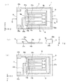
以下、本発明の実施の形態を図面に基づいて詳細に説明する。図1は、本発明の一実施
形態に係る音叉型振動素子1の構成を示す概略図であり、同図(a)は平面図、同図(b
)はQ−Q線に於ける断面図、同図(c)は裏面図である。
音叉型振動素子1は、圧電材料からなる矩形板状で枠体5と、枠体5の一辺から枠体5
の主平面(座標軸のX−Z平面)に平行で、且つ互いにZ軸方向に平行に突出する3個の
梁と、3個の梁の表裏面に夫々形成された駆動用電極と、前記駆動用電極から夫々延在し
、枠体5の端部に形成したパッド電極と接続するリード電極と、を備えている。
矩形板状の枠体5は、同じ厚さ(Y軸方向)の4個の部材6、7、8、9より成り、部
材6の一方の端部と部材7の一方の端部とを接合し、部材7の他方の端部と部材8の一方
の端部とを接合し、部材8の他方の端部と部材9の一方の端部とを接合し、部材9の他方
の端部と部材6の他方の端部とを接合して、矩形板状の枠体5が構成される。ここで、枠
体5の部材9は他の部材6、7、8よりもZ軸方向に幅広であり、これを基体9と称する
。
なお、図1に示す座標軸(X、Y、Z)は音叉型振動素子1の方向を示す座標軸であり
、圧電結晶の結晶軸ではない。また、枠体5を矩形状と説明したが必ずしも矩形状である
必要はなく他の形状であってもよい。
Hereinafter, embodiments of the present invention will be described in detail with reference to the drawings. FIG. 1 is a schematic view showing a configuration of a tuning fork
) Is a cross-sectional view taken along the line Q-Q, and FIG.
The tuning fork
Three beams that are parallel to the principal plane (XZ plane of the coordinate axis) and project parallel to each other in the Z-axis direction, and the driving electrodes formed on the front and back surfaces of the three beams, respectively, A lead electrode extending from the electrode for use and connected to a pad electrode formed at an end of the frame 5.
The rectangular plate-shaped frame 5 is composed of four
Note that the coordinate axes (X, Y, Z) shown in FIG. 1 are coordinate axes indicating the direction of the tuning fork
音叉型振動素子1は、表裏関係にある2つの主面(X−Z面)を有する基体(部材)9
と、基体9により夫々一端部を片持ち支持され、前記各主面の面方向と平行で、且つZ軸
方向に平行に突出した第1梁11、第2梁12、及び第1梁11と第2梁12との間の基
体9部分により片持ち支持されて前記各梁11、12と同じ方向に突出した第3梁13と
、を備えた音叉型振動片を含んでいる。
第1及び第2梁11、12の表面の少なくとも一部には、夫々第1駆動用電極11a、
12aが形成されている。第1駆動用電極11a、12aの少なくとも一部と対向する第
1及び第2梁11、12の裏面の部位には、夫々第2駆動電極11b、12bが形成され
ている。第3梁13の表面の少なくとも一部には、第3駆動用電極13aが形成され、第
3駆動用電極13aの少なくとも一部と対向する第3梁13の裏面の部位に第4駆動電極
13bが形成されている。
第1駆動電極11a、12a、第2駆動電極11b、12b、第3駆動電極13a及び
第4駆動電極13bは、夫々が形成された梁11、12、13の幅方向(X軸方向)の全
幅に渡って形成されている。
第1梁11の表面に形成した第1駆動用電極11aから、基体9の表面の端部に形成し
たパッド電極25aまでリード電極21aが延在され、パッド電極25aと接続されてい
る。同様に第3梁13の表面に形成した第3駆動用電極13aから、基体9の表面の端部
に形成したパッド電極26aまでリード電極23aが延在され、パッド電極26aと接続
されている。また、第2梁12の表面に形成した第1駆動用電極12aは、基体9、部材
8、7、6の表面に形成したリード電極22aにより、基体9の端部に形成したパッド電
極25aに接続されている。
The tuning fork
A
At least a part of the surface of the first and
12a is formed.
The
A
第2梁12の裏面に形成した第2駆動用電極12bから、基体9の裏面の端部に形成し
たパッド電極26bまでリード電極22bが延在され、パッド電極26bと接続されてい
る。同様に、第3梁13の裏面に形成した第4駆動用電極13bから、基体9の裏面の端
部に形成したパッド電極25bまでリード電極23bが延在され、パッド電極25bと接
続されている。また、第1梁11の裏面に形成した第2駆動用電極11bは、基体9、部
材6、7、8の裏面に形成したリード電極21bにより、基体9の端部のパッド電極26
bに接続されている。
基体9表面に形成されたパッド電極25aと、基体9裏面に形成されたパッド電極25
bとは導通させ、基体9表面に形成されたパッド電極26aと、基体9裏面に形成された
パッド電極26bとは導通させて用いる。
A
connected to b.
The
The
音叉型振動素子1は、枠体5と、枠体5の基体9から主面に平行に突出した第1梁及び
第2梁11、12及び、第1梁11と第2梁12との間の基体9部分により片持ち支持さ
れ各梁11、12と同じ方向に平行に突出した第3梁13と、を備えており、平板状の圧
電基板をフォトリソグラフィ技法とエッチング手法を用いて加工することにより製造され
る。つまり、枠体5部分を残し、各梁11、12、13はハーフエッチング加工して薄板
状の梁とし、これら以外の領域はエッチング加工して除去する一体的加工法を用いること
ができる。圧電基板としては、例えば水晶、タンタル酸リチウム、ニオブ酸リチウム、ラ
ンガサイト等がある。水晶基板を用いる場合、ATカット水晶基板(AT板)、BTカッ
ト水晶基板(BT板)、Yカット水晶基板(Y板;水晶の結晶軸Yに垂直な基板)などが
ある。AT板、BT板、Y板を用いれば、厚み方向に電圧を印加することにより、すべり
歪を容易に生じさせることができる。
The tuning fork
図1に示した例は平板状の水晶基板を加工した例である。水晶の結晶軸方向によりエッ
チング速度が異なるため、図1(a)、(b)、(c)に示すように、エッチング断面は
水晶基板の主面に垂直ではなく、傾斜面6a、7a、8a、9aが形成される。各傾斜面
6a、7a、8a、9aの角度は結晶軸の方向に依存する。
図1に示す音叉型振動素子は、水晶基板の一方の主面(表面)からエッチングを進め、
第1梁11、第2梁12、第3梁13が水晶基板の他方の面(裏面)に残るように形成さ
れ、枠体5と各梁11、12、13の間、及び各梁11、12、13間に開口部が形成さ
れるようにエッチングを制御する。
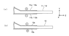
図1(b)に示すように、第3梁13(第1及び第2梁11、12)の一方の端部は、
基体9の緩やかな傾斜面(傾斜部)9aを介して基体9と結合している。つまり、基体9
の断面は、第3梁13(第1及び第2梁11、12)との連結部分から−Z軸方向に離れ
るに従い厚さが漸増するような形状になっている。
駆動用電極11a〜13b及びリード電極21a〜23bは、真空蒸着装置、スパッタ
装置等を用いてクロミウムCr、金Au等の金属を真空中で多層膜に成膜したものである
。この際、リード電極21a〜23bの断線を回避するため、基体9の緩やかな傾斜面9
a、枠体5の表裏面に形成することが望ましい。
The example shown in FIG. 1 is an example in which a flat crystal substrate is processed. Since the etching rate varies depending on the crystal axis direction of the crystal, as shown in FIGS. 1A, 1B, and 1C, the etching cross section is not perpendicular to the main surface of the crystal substrate, and the
The tuning fork type vibration element shown in FIG. 1 proceeds with etching from one main surface (surface) of the quartz substrate,
The
As shown in FIG. 1B, one end of the third beam 13 (first and
The
The cross section has a shape in which the thickness gradually increases as the distance from the connecting portion with the third beam 13 (the first and
The driving
a, It is desirable to form on the front and back of the frame 5.
図2は、パッド電極25a、26a間に励振電圧を印加した際に、第1及び第2梁11
、12の第1及び第2駆動用電極11a〜12bと、第3梁13の第3及び第4駆動用電
極13a、13bに、ある瞬間に生じる電圧の符号(+、−)を示した断面図である。第
1及び第2駆動用電極11a、12bと、第3及び第4駆動用電極13a、13bとでは
、印加される電圧が逆相となる。
FIG. 2 shows the first and
, Twelve first and
図3は、第1梁11の振動姿態を説明するための要部拡大断面図で、上部電極11aと
下部電極11b間に励振電圧が印加される。励振電圧が印加されると、第1梁11の第1
及び第2駆動用電極11a、11b間には励振電圧による電界が生じ、すべり歪が励起さ
れる。つまり、第1梁11の厚さの中心線より上部は図中右方へ変位し、厚さの中心線よ
り下部は図中左方へ変位する。つまり、図3の波線で示すような正弦波状の変位が生じる
。
この変位により第1梁11には一点鎖線示すY軸方向の屈曲振動が励振される。つまり
、第1梁11上に形成した第1駆動用電極11aと第2駆動用電極11b間の印加電圧に
より、第1梁11にはY軸方向の屈曲振動が励起される。第2梁12、第3梁13につい
ても同様であるので、説明を省略する。
FIG. 3 is an enlarged cross-sectional view of a main part for explaining the vibration state of the
In addition, an electric field due to the excitation voltage is generated between the
Due to this displacement, bending vibration in the Y-axis direction indicated by a one-dot chain line is excited in the
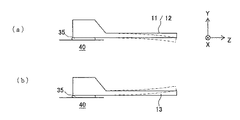
図4は、音叉型振動素子1を導電性接着剤35を用いて基台40に接着、固定し、パッ
ド電極25a、26a間に交流電圧を印加した際の第1及び第2梁11、12と、第3梁
13との振動の様子を示す断面図である。
図4の一点鎖線は、第1及び第2梁11、12と第3梁13のある瞬間の振動姿態を示
した断面図で、第1及び第2梁11、12と第3梁13とは逆相で振動している。つまり
、ある瞬間に第1及び第2梁11、12が下方(−Y軸方向)に屈曲するとき、第3梁1
3は上方(+Y軸方向)に屈曲するように振動している。
両側の梁(第1及び第2梁11、12)と中央の梁(第3梁13)とが逆相で駆動する
ことにより、基部9からの振動漏れを低減することができ、音叉型振動素子1のQ値を改
善することができるという効果がある。
圧電基板の一部領域を片面からエッチングし、前記領域を所望の厚みに加工し、この薄
くなった領域に再度エッチング加工を施して、前記音叉型振動片を形成し、音叉型振動片
に真空中で駆動電極を成膜して音叉型振動素子を形成する。このように、エッチング加工
を用いて前記音叉型振動片を形成すれば、小型化が容易であり、多量生産ができるという
効果がある。また、圧電基板を用いれば、成膜工程を1回で済ませることができるので、
製造工程が容易になるという効果がある。
FIG. 4 shows the first and
4 is a cross-sectional view showing an instantaneous vibration state of the first and
3 vibrates so as to bend upward (in the + Y-axis direction).
By driving the beams on both sides (first and
A part of the piezoelectric substrate is etched from one side, the region is processed to a desired thickness, and the thinned region is etched again to form the tuning fork type vibrating piece. A drive electrode is formed therein to form a tuning fork type vibration element. Thus, if the tuning fork type resonator element is formed by etching, there is an effect that it is easy to downsize and mass production is possible. In addition, if a piezoelectric substrate is used, the film forming process can be completed once,
There is an effect that the manufacturing process becomes easy.
第1、第2駆動電極11a、12a、11b、12b、及び第3、第4駆動電極13a
、13bは、1回の成膜工程で形成されるため、第1〜4駆動電極11a〜13bを第1
、第2及び第3梁11、12、13に、幅方向の全幅に渡って形成することが可能となり
、すべり歪を効率良く励起することができるという効果がある。
第1梁11、第2梁12及び第3梁13は、極めて薄く加工するので、前記駆動電極間
に生じるすべり歪により、屈曲振動を容易に励起させることができる。また、基体9は前
記梁との連結部分から離れるに従い厚さが漸増するように構成されているので、音叉型振
動素子1の支持が容易となると共に、屈曲振動の振動漏れを低減し、Q値を改善するとい
う効果がある。
また、水晶を用いて前記音叉型振動片を形成すると、加工精度が良く、小型化が容易に
なるという効果がある。また、材質のQ値も高いので、高Qで温度特性の良好な音叉型振
動素子1が得られるという効果がある。
First and
, 13b are formed in one film formation step, the first to
The second and
Since the
Further, when the tuning fork type resonator element is formed using quartz, there are effects that the processing accuracy is good and the miniaturization becomes easy. In addition, since the material has a high Q value, there is an effect that a tuning fork
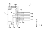
図5は、第2の実施例の音叉型振動素子2の構成を示す図であり、同図(a)は平面図
、同図(b)は断面図、同図(c)は裏面図である。第2の実施例の音叉型振動素子2が
、図1に示した音叉型振動素子1と異なる点は、部材7とリード電極22a、21bであ
る。水晶基板をフォトリソグラフィ技法とエッチング手法を用いて加工する際に、部材7
と、部材6及び部材8との境界部にハーフエッチングにより溝部を形成する工程を付加す
ればよい。この溝部に沿って折り取りすれば音叉型振動素子2の基板、即ち音叉型振動片
が形成される。駆動用電極11a〜13b、リード電極21a〜23aの形成法は上述し
た手法を用いて形成する。ただ、表面のリード電極22aとパッド電極25aとの接続と
、裏面のリード電極21bとパッド電極26bとの接続は、ボンディングワイヤを用いる
手法や、あるいは絶縁層を挟んでリード電極を多層化して接続する手法をとる必要がある
。
FIGS. 5A and 5B are diagrams showing the configuration of the tuning fork
And a step of forming a groove by half etching at the boundary between the member 6 and the member 8 may be added. By folding along the groove, a substrate of the tuning fork
図6は、第3の実施例の音叉型振動素子3の構成を示す平面図である。音叉型振動素子
3が、図5に示した第2の実施例の音叉型振動素子2と異なる点は、部材6と部材8であ
る。水晶基板をフォトリソグラフィ技法とエッチング手法を用いて加工する際に、基体9
(部材9)と部材6との境界と、基体9(部材9)と部材8の境界と、の境界部にハーフ
エッチングにより溝部を形成する工程を付加すればよい。この溝部に沿って折り取りすれ
ば音叉型振動素子3の基板である音叉型振動片が形成される。駆動用電極、リード電極の
形成法は上述した通りである。
FIG. 6 is a plan view showing the configuration of the tuning fork type vibration element 3 of the third embodiment. The tuning fork type vibration element 3 is different from the tuning fork
What is necessary is just to add the process of forming a groove part by a half etching in the boundary part of the boundary of (member 9) and member 6, and the boundary of the base | substrate 9 (member 9) and member 8. If it is broken along the groove, a tuning fork type vibrating piece as a substrate of the tuning fork type vibration element 3 is formed. The method for forming the drive electrode and the lead electrode is as described above.
図7は本発明に係る音叉型振動子50の構成を示す断面図である。音叉型振動子50は
、実施例1乃至3の何れかの音叉型振動素子と、音叉型振動素子を収容するパッケージ5
1と、を備えている。パッケージ51は、パッケージ本体51aと、蓋部材51bとから
なり、パッケージ本体51aの外底部には外部接続端子52が形成されている。パッケー
ジ本体51aの内部には前記音叉型振動素子を例えば、導電性接着材53を介して搭載す
るための台座53が設けられている。台座53の表面には接続電極が設けられ、接続電極
がパッケージ本体51aの外部接続端子52と導通している。パッケージ本体51aに前
記音叉型振動素子を収容した後、パッケージ本体51aを真空状態で蓋部材51bを抵抗
溶接、あるいは低融点のガラス等で気密封止する。
実施例1乃至3の何れかの音叉型振動素子を用いて音叉型振動子を構成するので、小型
で、Q値が大きく、温度特性が良好で安価な音叉型振動子が得られるという効果がある。
FIG. 7 is a cross-sectional view showing a configuration of a
1 is provided. The
Since the tuning fork vibrator is configured using the tuning fork vibrator of any one of the first to third embodiments, there is an effect that a tuning fork vibrator that is small in size, has a large Q value, has good temperature characteristics, and is inexpensive can be obtained. is there.
図8は本発明に係る発振器60の構成を示す断面図である。発振器60は、実施例1乃
至3の何れかの音叉型振動素子と、音叉型振動素子を励振するIC回路55と、前記音叉
型振動素子とIC回路55とを収容するパッケージ51と、を備えている。パッケージ5
1は、パッケージ本体51aと、蓋部材51bとからなり、パッケージ本体51aの外底
部には外部接続端子52が形成されている。パッケージ本体51aの内部にはIC用パッ
ド電極と前記音叉型振動素子を例えば、導電性接着材53を介して搭載するための台座5
3が設けられている。台座53の表面には接続電極が設けられ、接続電極と、前記IC用
パッド電極とはパッケージ本体51aの外部接続端子52と導通している。パッケージ本
体51aに前記音叉型振動素子と、IC回路55とを収容した後、パッケージ本体51a
を真空状態で蓋部材51bを抵抗溶接、あるいは低融点のガラス等で気密封止する。
実施例1乃至3の何れかの音叉型振動素子と、IC回路とを用いて発振器を構成するの
で、小型で安価な発振器が得られるという効果がある。
FIG. 8 is a cross-sectional view showing the configuration of the
1 includes a
3 is provided. A connection electrode is provided on the surface of the
The
Since the oscillator is configured using the tuning fork type vibration element according to any of the first to third embodiments and the IC circuit, there is an effect that a small and inexpensive oscillator can be obtained.
1、2、3…音叉型振動素子、5…枠体、6、7、8…部材、9…基体(部材)、6a、
7a、8a、9a…傾斜面、11…第1梁、12…第2梁、13…第3梁、11a、12
a…第1駆動用電極、11b、12b…第2駆動電極、13a…第3駆動用電極、13b
…第4駆動電極、21a、22a、23a、21b、22b、23b…リード電極、25
a、25b、26a、26b…パッド電極、35…導電性接着剤、40…基台、50…音
叉型振動子、51…パッケージ、51a…パッケージ本体、51b…蓋部材、52…外部
接続端子、53…台座、55…IC回路、60…発振器
1, 2, 3, ... tuning fork type vibration element, 5 ... frame, 6, 7, 8 ... member, 9 ... base (member), 6a,
7a, 8a, 9a ... inclined surface, 11 ... first beam, 12 ... second beam, 13 ... third beam, 11a, 12
a ... 1st drive electrode, 11b, 12b ... 2nd drive electrode, 13a ... 3rd drive electrode, 13b
... 4th drive electrode, 21a, 22a, 23a, 21b, 22b, 23b ... Lead electrode, 25
a, 25b, 26a, 26b ... pad electrode, 35 ... conductive adhesive, 40 ... base, 50 ... tuning fork vibrator, 51 ... package, 51a ... package body, 51b ... lid member, 52 ... external connection terminal, 53 ... pedestal, 55 ... IC circuit, 60 ... oscillator
Claims (6)
各主面の面方向と平行に突出した第1梁及び第2梁、及び、前記第1梁と前記第2梁との
間の前記基体部分により片持ち支持されて前記各梁と同じ方向に突出した第3梁、を備え
た音叉型振動片と、
前記第1及び第2梁の表面の少なくとも一部に夫々形成された第1駆動用電極と、前記
第1駆動用電極の少なくとも一部と対向する前記第1及び第2梁の裏面の部位に夫々形成
された第2駆動電極と、前記第3梁の表面の少なくとも一部に形成された第3駆動用電極
と、前記第3駆動用電極の少なくとも一部と対向する前記第3梁の裏面の部位に形成され
た第4駆動電極と、を備え、
前記第1駆動電極と前記第2駆動電極との間には、前記第3駆動電極と前記第4駆動電
極との間に印加される電位とは逆電位となる信号が印加され、
前記第1梁と前記第2梁および前記第3梁とは、前記表裏の方向である厚み方向に生じ
た電界によって厚みすべり歪みを生じる圧電材であることを特徴とする音叉型振動素子。 A base having two main surfaces in a front-back relationship, a first beam and a second beam that are cantilevered by the base and project in parallel with the surface direction of each main surface, and the first beam and the first beam A tuning fork-type vibrating piece including a third beam that is cantilevered by the base portion between the two beams and protrudes in the same direction as each of the beams;
A first driving electrode formed on at least a part of the surface of each of the first and second beams; and a back surface of the first and second beams facing at least a part of the first driving electrode. A second driving electrode formed respectively, a third driving electrode formed on at least a part of the surface of the third beam, and a back surface of the third beam facing at least a part of the third driving electrode. A fourth drive electrode formed at the site of
A signal having a potential opposite to that applied between the third drive electrode and the fourth drive electrode is applied between the first drive electrode and the second drive electrode,
The tuning fork type vibration element, wherein the first beam, the second beam, and the third beam are piezoelectric materials that cause a thickness-slip distortion due to an electric field generated in a thickness direction that is a direction of the front and back surfaces.
れぞれが形成された梁の幅方向の全幅に渡って延在していることを特徴とする請求項1に
記載の音叉型振動素子。 The first drive electrode, the second drive electrode, the third drive electrode, and the fourth drive electrode each extend over the entire width in the width direction of the beam on which the first drive electrode, the second drive electrode, the third drive electrode, and the fourth drive electrode are formed. Item 2. A tuning-fork type vibration element according to Item 1.
さが漸増する構成であることを特徴とする請求項1に記載の音叉型振動素子。 2. The tuning fork type vibration element according to claim 1, wherein the thickness of the base body gradually increases as the distance from the connection portion between the first beam, the second beam, and the third beam increases.
項に記載の音叉型振動素子。 The tuning fork type vibrating element according to any one of claims 1 to 3, wherein the tuning fork type vibrating piece is made of quartz.
パッケージと、を備えたことを特徴とする音叉型振動子。 A tuning fork vibrator comprising the tuning fork vibrator according to any one of claims 1 to 4 and a package that accommodates the tuning fork vibrator.
IC回路と、前記音叉型振動素子及び前記IC回路を収容するパッケージと、を備えたこ
とを特徴とする発振器。 A tuning fork type vibration element according to any one of claims 1 to 4, an IC circuit that excites the tuning fork type vibration element, and a package that houses the tuning fork type vibration element and the IC circuit. An oscillator characterized by.
Priority Applications (1)
| Application Number | Priority Date | Filing Date | Title |
|---|---|---|---|
| JP2009251732A JP2011097499A (en) | 2009-11-02 | 2009-11-02 | Tuning-fork type vibrating element, tuning-fork type vibrator and oscillator |
Applications Claiming Priority (1)
| Application Number | Priority Date | Filing Date | Title |
|---|---|---|---|
| JP2009251732A JP2011097499A (en) | 2009-11-02 | 2009-11-02 | Tuning-fork type vibrating element, tuning-fork type vibrator and oscillator |
Publications (2)
| Publication Number | Publication Date |
|---|---|
| JP2011097499A true JP2011097499A (en) | 2011-05-12 |
| JP2011097499A5 JP2011097499A5 (en) | 2012-08-30 |
Family
ID=44113911
Family Applications (1)
| Application Number | Title | Priority Date | Filing Date |
|---|---|---|---|
| JP2009251732A Withdrawn JP2011097499A (en) | 2009-11-02 | 2009-11-02 | Tuning-fork type vibrating element, tuning-fork type vibrator and oscillator |
Country Status (1)
| Country | Link |
|---|---|
| JP (1) | JP2011097499A (en) |
Citations (2)
| Publication number | Priority date | Publication date | Assignee | Title |
|---|---|---|---|---|
| JPS5689118A (en) * | 1979-12-21 | 1981-07-20 | Citizen Watch Co Ltd | Longitudinal oscillator |
| JPS5853215A (en) * | 1981-09-25 | 1983-03-29 | Seiko Instr & Electronics Ltd | Tuning fork type crystal oscillator |
-
2009
- 2009-11-02 JP JP2009251732A patent/JP2011097499A/en not_active Withdrawn
Patent Citations (2)
| Publication number | Priority date | Publication date | Assignee | Title |
|---|---|---|---|---|
| JPS5689118A (en) * | 1979-12-21 | 1981-07-20 | Citizen Watch Co Ltd | Longitudinal oscillator |
| JPS5853215A (en) * | 1981-09-25 | 1983-03-29 | Seiko Instr & Electronics Ltd | Tuning fork type crystal oscillator |
Similar Documents
| Publication | Publication Date | Title |
|---|---|---|
| JP6078968B2 (en) | Manufacturing method of vibrating piece | |
| JP2004200917A (en) | Piezoelectric vibrating piece, piezoelectric device employing the same, cellular telephone device employing the piezoelectric device, and electronic equipment employing the piezoelectric device | |
| JP6482169B2 (en) | Vibrating piece, vibrator, oscillator, electronic device and moving object | |
| JP5531319B2 (en) | Crystal resonator, crystal unit, and crystal oscillator manufacturing method | |
| US9299912B2 (en) | Vibrator element, manufacturing method of vibrator element, sensor unit, and electronic apparatus | |
| JP3743913B2 (en) | Quartz crystal unit, crystal unit, crystal oscillator, and manufacturing method thereof | |
| US8525606B2 (en) | Vibrator element, vibrator, oscillator, and electronic device | |
| JP2012074807A (en) | Piezoelectric vibration element, surface-mounted piezoelectric vibrator and surface-mounted piezoelectric oscillator | |
| JP2005123828A (en) | Tuning-fork piezo-electric oscillation piece and piezo-electric device | |
| JP5923862B2 (en) | Vibrating piece, vibrator, oscillator and electronic device | |
| JP5533349B2 (en) | Bending vibrator, bending vibrator, oscillator, and electronic device | |
| JP2003273703A (en) | Quartz vibrator and its manufacturing method | |
| JP2011097499A (en) | Tuning-fork type vibrating element, tuning-fork type vibrator and oscillator | |
| JP3749917B2 (en) | Manufacturing method of crystal oscillator | |
| JP5732903B2 (en) | Vibration element, vibrator, oscillator, gyro sensor and electronic equipment | |
| JP4074934B2 (en) | Crystal oscillator and manufacturing method thereof | |
| JP4697196B2 (en) | Crystal unit and crystal oscillator manufacturing method | |
| JP2003273696A (en) | Method for manufacturing crystal unit and method of manufacturing crystal oscillator | |
| JP4697190B2 (en) | Manufacturing methods for crystal units and crystal units | |
| JP4074935B2 (en) | Quartz crystal oscillator and crystal oscillator manufacturing method | |
| JP2012182610A (en) | Vibration piece, vibrator, oscillator and electronic apparatus | |
| JP4697196B6 (en) | Crystal unit and crystal oscillator manufacturing method | |
| JP2012023526A (en) | Bending vibration piece, vibrator, oscillator, and electronic apparatus | |
| JP2012160995A (en) | Vibrator element, vibrator, oscillator, and electronic apparatus | |
| JP2004215204A (en) | Crystal oscillator, and method of manufacturing crystal oscillator |
Legal Events
| Date | Code | Title | Description |
|---|---|---|---|
| A521 | Request for written amendment filed |
Free format text: JAPANESE INTERMEDIATE CODE: A523 Effective date: 20120711 |
|
| A621 | Written request for application examination |
Free format text: JAPANESE INTERMEDIATE CODE: A621 Effective date: 20120711 |
|
| A977 | Report on retrieval |
Free format text: JAPANESE INTERMEDIATE CODE: A971007 Effective date: 20130226 |
|
| A131 | Notification of reasons for refusal |
Free format text: JAPANESE INTERMEDIATE CODE: A131 Effective date: 20130305 |
|
| A761 | Written withdrawal of application |
Free format text: JAPANESE INTERMEDIATE CODE: A761 Effective date: 20130402 |