JP4074935B2 - Quartz crystal oscillator and crystal oscillator manufacturing method - Google Patents
Quartz crystal oscillator and crystal oscillator manufacturing method Download PDFInfo
- Publication number
- JP4074935B2 JP4074935B2 JP2003040391A JP2003040391A JP4074935B2 JP 4074935 B2 JP4074935 B2 JP 4074935B2 JP 2003040391 A JP2003040391 A JP 2003040391A JP 2003040391 A JP2003040391 A JP 2003040391A JP 4074935 B2 JP4074935 B2 JP 4074935B2
- Authority
- JP
- Japan
- Prior art keywords
- tuning fork
- crystal
- frequency
- groove
- crystal oscillator
- Prior art date
- Legal status (The legal status is an assumption and is not a legal conclusion. Google has not performed a legal analysis and makes no representation as to the accuracy of the status listed.)
- Expired - Lifetime
Links
Images


Landscapes
- Oscillators With Electromechanical Resonators (AREA)
- Piezo-Electric Or Mechanical Vibrators, Or Delay Or Filter Circuits (AREA)
Description
【0001】
【発明の属する技術分野】
本発明は屈曲モードで振動する音叉腕と音叉基部を具えて構成される音叉形状の水晶振動子と増幅器とコンデンサーと抵抗素子とを具えて構成される水晶発振器とその製造方法に関する。特に、小型化、高精度化、耐衝撃性、低廉化の要求の強い情報通信機器用の基準信号源として最適な水晶発振器で、新形状、新電極構成及び最適寸法を有する超小型の音叉形状の屈曲水晶振動子から構成され、基本波モード振動の周波数が出力信号である水晶発振器に関する。
【0002】
【従来の技術】
従来の水晶発振器は増幅器とコンデンサーと抵抗素子と音叉腕の上下面と側面に電極が配置された音叉型屈曲水晶振動子から成る水晶発振器がよく知られている。図9には、この従来例の水晶発振器に用いられている音叉形状の屈曲水晶振動子200の概観図を示す。図9において水晶振動子200は2本の音叉腕201,202と音叉基部230とを具えている。図10には図9の音叉腕の断面図を示す。図10に示すように、励振電極は音叉腕の上下面と側面に配置されている。音叉腕の断面形状は一般的には長方形をしている。一方の音叉腕の断面の上面には電極203が下面には電極204が配置されている。側面には電極205と206が設けられている。他方の音叉腕の上面には電極207が下面には電極208が、更に側面には電極209,210が配置され2電極端子H−H′構造を成している。今、H−H′間に直流電圧を印加すると電界は矢印方向に働く。その結果、一方の音叉腕が内側に曲がると他方の音叉腕も内側に曲がる。この理由は、x軸方向の電界成分Exが各音叉腕の内部で方向が反対になるためである。交番電圧を印加することにより振動を持続することができる。又、特開昭56−65517と特開2000−223992(P2000−223992A)では、音叉腕に溝を設け、且つ、電極構成について開示されている。
【0003】
【発明が解決しようとする課題】
音叉型屈曲水晶振動子では、電界成分Exが大きいほど等価直列抵抗R1が小さくなり、品質係数Q値が大きくなる。しかしながら、従来から使用されている音叉型屈曲水晶振動子は、図10で示したように、各音叉腕の上下面と側面の4面に電極を配置している。そのために電界が直線的に働かず、かかる音叉型屈曲水晶振動子を小型化させると、電界成分Exが小さくなってしまい、等価直列抵抗R1が大きくなり、品質係数Q値が小さくなるなどの課題が残されていた。同時に、時間基準として高精度な、即ち、高い周波数安定性を有し、高調波モード振動を抑えた屈曲水晶振動子を得ることが課題として残されていた。又、前記課題を解決する方法として、例えば、特開昭56−65517では音叉腕に溝を設け、且つ、溝の構成と電極構成について開示している。しかしながら、溝の構成、寸法と振動モード並びに基本波モード振動での等価直列抵抗R1と高調波モード振動での等価直列抵抗Rnとの関係及び周波数安定性に関係するフィガーオブメリットMについては全く開示されていない。又、従来の水晶振動子や前記溝を設けた振動子を従来の回路に接続し、水晶発振回路を構成すると、基本波振動モードの出力信号が衝撃や振動などの影響で出力信号が高調波モード振動の周波数に変化、検出される等の問題が発生していた。このようなことから、衝撃や振動を受けても、それらの影響を受けない高調波モード振動を抑えた基本波モードで振動する音叉形状の屈曲水晶振動子を具えた水晶発振器が所望されていた。更に、水晶発振器の消費電流を低減するために、負荷容量CLを小さくすると高調波モードの振動がし易くなり、基本波モード振動の出力周波数が得られない等の課題が残されていた。それ故、基本波モードで振動する超小型で、等価直列抵抗R1の小さい、品質係数Q値が高くなるような新形状で、電気機械変換効率の良い溝の構成と電極構成を有する音叉形状の屈曲水晶振動子を具え、出力信号が基本波モード振動の周波数で、高い周波数安定性(高い時間精度)を有し、消費電流の少ない水晶発振器が所望されていた。
【0004】
【課題を解決するための手段】
本発明は、以下の方法で従来の課題を有利に解決した屈曲モードで振動する音叉形状の水晶振動子を具えた水晶発振器とその製造方法を提供することを目的とするものである。
【0005】
即ち、本発明の水晶発振器の製造方法の第1の態様は、水晶振動子と増幅器とコンデンサーと抵抗素子とを具えて構成される水晶発振回路を具えた水晶発振器の製造方法で、前記水晶振動子は、少なくとも第1音叉腕と第2音叉腕と音叉基部とを具えて構成される音叉形屈曲水晶振動子で、第1音叉腕と第2音叉腕は上面と下面と側面とを有し、第1音叉腕の上下面の少なくとも一面に溝を形成する工程と、第2音叉腕の上下面の少なくとも一面に溝を形成する工程と、溝と第1音叉腕と第2音叉腕の側面に電極が配置され、溝の側面に配置された電極とその電極に対抗する音叉腕の側面の電極とが互いに異極である2電極端子を構成し、かつ、第1音叉腕と第2音叉腕が逆相で振動するように溝と電極を形成する工程と、音叉形屈曲水晶振動子の発振周波数を調整する工程と、音叉形屈曲水晶振動子を表面実装型、又は円筒型のユニットに収納する工程と、を少なくとも有し、第1音叉腕と第2音叉腕が逆相で振動するように、前記2電極端子の内、1電極端子は第1音叉腕の上下面の少なくとも一面に形成された溝に配置された電極と第2音叉腕の両側面に配置された電極から構成され、且つ、上下面の少なくとも一面に形成された溝に配置された前記電極と両側面に配置された前記電極とが接続され、他の1電極端子は第1音叉腕の両側面に配置された電極と第2音叉腕の上下面の少なくとも一面に形成された溝に配置された電極から構成され、且つ、両側面に配置された前記電極と上下面の少なくとも一面に形成された溝に配置された前記電極とが接続されていて、前記水晶発振器は前記音叉形屈曲水晶振動子の基本波モード振動の容量比r1が2次高調波モード振動の容量比r2より小さく、かつ、基本波モード振動のフイガーオブメリットM1が高調波モード振動のフイガーオブメリットMnより大きい音叉形屈曲水晶振動子を具えて構成されていて、前記音叉形屈曲水晶振動子が水晶ウエハ内に形成され、前記音叉形屈曲水晶振動子の基本波モード振動の基準周波数が32.768kHzで、前記音叉形屈曲水晶振動子の発振周波数が前記基準周波数に対して、−9000PPM〜+5000PPMの範囲内にあるように水晶ウエハ内で周波数が調整される水晶発振器の製造方法である。
【0006】
本発明の水晶発振器の製造方法の第2の態様は、基本波モード振動の基準周波数が、32.768kHzである音叉形屈曲水晶振動子を収納するケース内に収納した後に、前記音叉形屈曲水晶振動子の発振周波数が前記基準周波数に対して、−100PPM〜+100PPMの範囲内にあるように周波数が調整され、その周波数調整の後にケースと蓋が接合され、前記発振周波数が水晶発振回路の出力周波数である第1の態様に記載の水晶発振器の製造方法である。
本発明の水晶発振器の製造方法の第3の態様は、基本波モード振動の基準周波数が、32.768kHzである音叉形屈曲水晶振動子を収納するケース内に収納した後に、ケースと蓋が接合され、その接合の後に、前記音叉形屈曲水晶振動子の発振周波数が前記基準周波数に対して、−50PPM〜+50PPMの範囲内にあるように周波数が調整され、前記発振周波数が水晶発振回路の出力周波数である第1の態様に記載の水晶発振器の製造方法である。
【0007】
【作用】
このように、本発明は屈曲モードで振動する音叉形状の水晶振動子を具えた水晶発振器で、しかも、音叉形状の溝と電極の構成を改善し、増幅回路と帰還回路との関係を示すことにより、高調波モード振動を抑え、基本波モードで振動する周波数を出力する水晶発振器を得る事ができる。
【0008】
加えて、音叉腕の中立線を挟んだ(含む)中央部に溝を設け、且つ、電極を配置し、溝の寸法の最適化を図る事により、等価直列抵抗R1が小さく、Q値が高く、電気機械変換効率の良い屈曲モードで振動する超小型の音叉形状の屈曲水晶振動子が得られる。と同時に、帰還回路の負荷容量を小さくできる。その結果、消費電流の少ない水晶発振器が得られる。
【0009】
【本発明の実施の形態】
以下、本発明の実施例を図面に基づき具体的に述べる。
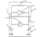
図1は本発明の水晶発振器を構成する水晶発振回路図の一実施例である。本実施例では、水晶発振回路1は増幅器(CMOSインバータ)2、帰還抵抗4、ドレイン抵抗7、コンデンサー5,6と音叉形状の屈曲水晶振動子3から構成されている。即ち、水晶発振回路1は、増幅器2と帰還抵抗4から成る増幅回路8とドレイン抵抗7、コンデンサー5,6と屈曲水晶振動子3から成る帰還回路9から構成されている。更に、基本波モードで振動する音叉形状の屈曲水晶振動子3を具えて構成される水晶発振回路1の出力信号はバッフア回路(図示されていない)を通してドレイン側から出力される。即ち、基本波モード振動の周波数がバッフア回路を通して出力信号として出力される。本発明では、基本波モード振動の周波数は10kHz〜200kHzが用いられる。又、本発明では、前記出力信号の周波数を分周回路又は逓倍回路によって分周又は逓倍された周波数も基本波モード振動の周波数に含まれる。さらに詳細には、本実施例の水晶発振器は水晶発振回路とバッフア回路とを具えて構成されている。換言するならば、水晶発振回路は増幅回路と帰還回路から構成され、増幅回路は少なくとも増幅器から構成され、帰還回路は少なくとも音叉形状の屈曲水晶振動子とコンデンサーから構成されている。又、本実施例の水晶発振器に用いられる音叉形状の屈曲水晶振動子は図3から図6で詳述される。
【0010】
図2は図1の帰還回路図を示す。今、屈曲モードで振動する音叉形状の水晶振動子の角周波数をωi、ドレイン抵抗7の抵抗をRd、コンデンサー5、6の容量をCg、Cd、水晶のクリスタルインピーダンスをRei,入力電圧をV1,出力電圧をV2とすると、帰還率βiはβi=|V2|i/|V1|iで定義される。但し、iは屈曲振動モードの振動次数を表し、例えば、i=1のとき、基本波モード振動、i=2のとき、2次高調波モード振動、i=3のとき、3次高調波モード振動である。即ち、i=nのとき、n次高調波モード振動であるが、以下単に、高調波モード振動と言う。更に、負荷容量CLはCL=CgCd/(Cg+Cd)で与えられ、Cg=Cd=CgsとRd>>Reiとすると、帰還率βiはβi=1/(1+kCL 2)で与えられる。但し、kはωi、Rd、Reiの関数で表される。又、Reiは近似的に等価直列抵抗Riに等しくなる。
【0011】
このように、帰還率βiと負荷容量CLとの関係から、負荷容量CLが小さくなると、基本波振動モードと高調波振動モードの共振周波数の帰還率はそれぞれ大きくなることが良く分かる。それ故、負荷容量CLが小さくなると、基本波モード振動よりも高調波モード振動の方が発振し易くなる。その理由は高調波モード振動の最大振動振幅が基本波モード振動の最大振動振幅より小さいために、発振持続条件である振幅条件と位相条件を同時に満足するためである。
【0012】
本発明の水晶発振器は、消費電流が少なく、しかも、出力周波数が高い周波数安定性(高い時間精度)を有する、基本波モード振動の周波数である水晶発振器を提供することを目的としている。それ故、消費電流を少なくするために、本実施例では、負荷容量CLは10pF以下を用いる。より消費電流を少なくするには、消費電流は負荷容量に比例するので、CL=8pF以下が好ましい。ここで言う、容量Cg、Cdは回路の浮遊容量を含まない数値であるが、実際には、回路構成により浮遊容量が存在する。それ故、本実施例では、この回路構成による浮遊容量を含んだ負荷容量CLは18pF以下を用いる。また、高調波モードの振動を抑え、発振器の出力信号が基本波モード振動の周波数を得るために、α1/αn>βn/β1とα1β1>1を満足するように本実施例の水晶発振回路は構成される。但し、α1、αnは基本波モード振動と高調波モード振動の増幅回路の増幅率で、β1、βnは基本波モード振動と高調波モード振動の帰還回路の帰還率である。即ち、n=2、3のとき、それぞれ、2次、3次高調波モード振動である。
【0013】
換言するならば、増幅回路の基本波モード振動の増幅率α1と高調波モード振動の増幅率αnとの比が帰還回路の高調波モード振動の帰還率βnと基本波モード振動の帰還率β1との比より大きく、かつ、基本波モード振動の増幅率α1と基本波モード振動の帰還率β1の積が1より大きくなるように構成される。このような構成により、消費電流の少ない、出力信号が基本波モード振動の周波数である水晶発振器が実現できる。更に、高い周波数安定性については後述される。
【0014】
又、本実施例の水晶発振回路を構成する増幅回路の増幅部は負性抵抗−RLiでその特性を示すことができる。i=1のとき基本波モード振動の負性抵抗で、i=nのとき高調波モード振動の負性抵抗である。即ち、n=2,3のとき、2次、3次高調波モード振動の負性抵抗である。本実施例の水晶発振器は、増幅回路の基本波モード振動の負性抵抗の絶対値|−RL1|と基本波モード振動の等価直列抵抗R1との比が増幅回路の高調波モード振動の負性抵抗の絶対値|−RLn|と高調波モード振動の等価直列抵抗Rnとの比より大きくなるように発振回路が構成されている。即ち、|−RL1|/R1>|−RLn|/Rnを満足するように構成されている。このように水晶発振回路を構成することにより、高調波モード振動の発振起動が抑えられ、その結果、基本波モード振動の発振起動が得られるので基本波モード振動の周波数が出力信号として得られる。
【0015】
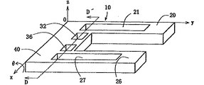
図3は本発明の第1実施例の水晶発振器に用いられる屈曲モードで振動する音叉形状の屈曲水晶振動子10の外観図とその座標系を示すものである。座標系O、電気軸x、機械軸y、光軸zからなるO−xyzを構成している。本実施例の音叉形状の屈曲水晶振動子10は音叉腕20、音叉腕26と音叉基部40とから成り、音叉腕20と音叉腕26は音叉基部40に接続されている。また、音叉腕20と音叉腕26はそれぞれ上面と下面と側面とを有する。更に、音叉腕20の上面には中立線を挟んで、即ち、中立線を含むように溝21が設けられ、又、音叉腕26の上面にも音叉腕20と同様に溝27が設けられるとともに、さらに、音叉基部40に溝32と溝36とが設けられている。なお、角度θは、x軸廻りの回転角であり、通常0〜10°の範囲で選ばれる。又、音叉腕20、26の下面にも上面と同様に溝が設けられている。
【0016】
図4は、図3の音叉形状の屈曲水晶振動子10の音叉基部40のD−D′断面図を示す。図4では図3の水晶振動子の音叉基部40の断面形状並びに電極配置について詳述する。音叉腕20と連結する音叉基部40には溝21,22が設けられている。同様に、音叉腕26と連結する音叉基部40には溝27,28が設けられている。更に、溝21と溝27との間には更に溝32と溝36とが設けられている。又、溝22と溝28との間にも溝33と溝37とが設けられている。そして、溝21と溝22には電極23,24が、溝32,33,36,37には電極34,35,38,39が、溝27と溝28には電極29,30が配置され、音叉基部40の両側面には電極25,31が配置されている。詳細には、溝の側面に電極が配置され、前記電極に対抗して極性の異なる電極が配置されている。
【0017】
また、音叉形状の屈曲水晶振動子10は厚みtを有し、溝は厚みt1を有している。ここで言う厚みt1は溝の一番深いところの厚みを言う。その理由は水晶は異方性の材料のために、化学的エッチング法では各結晶軸の方向によりエッチングスピードが異なる。それ故、化学的エッチング法では溝の深さにバラツキが生じ、図4に示した一様な形状に加工するのが極めて難しいためである。本実施例では、溝の厚みt1と音叉腕又は音叉腕と音叉基部の厚みtとの比(t1/t)が0.79より小さくなるように、好ましくは、0.01〜0.79となるように溝が音叉腕又は音叉腕と音叉基部に形成されている。特に、音叉基部の歪みを大きくするために、音叉基部の溝の厚みと音叉基部の厚みの比を0.01〜0.025にする事が好ましい。このように形成することにより、音叉腕又は音叉腕と音叉基部の溝側面電極とそれに対抗する側面の電極との間の電界Exが大きくなる。すなわち、電気機械変換効率の良い屈曲振動子が得られる。即ち、容量比の小さい音叉形状の屈曲水晶振動子が得られる。更に、本実施例では、音叉基部の溝と溝との間にさらに溝32,33,36,37が設けられているので、その電界強度はより一層大きくなり、より電気機械変換効率が良くなる。又、本実施例では、音叉基部40の上面に溝32,36が、下面に溝33,37が設けられているが、片面にのみ設けても良い。
【0018】
更に、電極25,29,30,34,35は一方の同極に、電極23,24,31,37,38,39は他方の同極になるように配置されていて、2電極端子構造E−E′を構成する。即ち、z軸方向に対抗する溝電極は同極に、且つ、x軸方向に対抗する電極は異極になるように構成されている。今、2電極端子E−E′に直流電圧を印加(E端子に正極、E′端子に負極)すると電界Exは図4に示した矢印のように働く。電界Exは水晶振動子の側面と溝内の側面とに配置された電極により電極に垂直に、即ち、直線的に引き出されるので、電界Exが大きくなり、その結果、発生する歪の量も大きくなる。従って、音叉形状の屈曲水晶振動子を小型化させた場合でも、等価直列抵抗R1の小さい、品質係数Q値の高い屈曲モードで振動する音叉形状の水晶振動子が得られる。
【0019】
図5は図3の音叉形状の屈曲水晶振動子10の上面図を示すものである。図5では溝21,27の配置及び寸法について特に詳述する。音叉腕20の中立線41を挟むようにして溝21が設けられている。他方の音叉腕26も中立線42を挟むようにして溝27が設けられている。更に、本実施例の音叉形状の屈曲水晶振動子10では、音叉基部40の、溝21と溝27との間に挟まれた部分にも溝32と溝36とが設けられている。それら溝21,27及び溝32,36を設けたことで、音叉形状の屈曲水晶振動子10には、先に述べたように、電界Exが図4に示した矢印のように働き、電界Exは水晶振動子の側面と溝内の側面とに配置された電極により電極に垂直に、即ち、直線的に引き出され、特に音叉基部の電界Exが大きくなり、その結果、発生する歪の量も大きくなる。このように、本実施例の音叉形状の屈曲水晶振動子10の形状と電極構成とは、音叉型屈曲水晶振動子を小型化した場合でも電気的諸特性に優れた、即ち、等価直列抵抗R1の小さい、品質係数Q値の高い水晶振動子が実現できる。
【0020】
更に、部分幅W1、W3と溝幅W2とすると、音叉腕20,26の腕幅WはW=
![]()
【0021】
これに対して、溝21および溝27の長さl1について本実施例では、溝21,27が音叉腕20,26から音叉基部40の長さl2にまで延在し、基部の溝の長さl3となるような寸法とされている。それ故、音叉腕20,26に設けられた溝の長さは(l1−l3)で与えられ、R1の小さい振動子を得るために、(l1−l3)/(l−l2)が0.4〜0.8の値を有する。更に、音叉形状の屈曲水晶振動子10の全長lは要求される周波数や収納容器の大きさなどから決定される。と共に、基本波モードで振動する良好な音叉形状の屈曲水晶振動子を得るためには、溝の長さl1と全長lとの間には密接な関係が存在する。
【0022】
すなわち、音叉腕20,26又は音叉腕20,26と音叉基部40に設けられた溝の長さl1と音叉形状の屈曲水晶振動子の全長lとの比(l1/l)が0.2〜0.78となるように溝の長さは設けられる。このように形成する理由は、不要振動である高調波モード振動、特に、2次、3次高調波モード振動を抑圧する事ができると共に基本波モード振動の周波数安定性を高めることができる。それ故、基本波モードで容易に振動する良好な音叉形状の屈曲水晶振動子が実現できる。さらに詳述するならば、基本波モードで振動する音叉形状の屈曲水晶振動子の等価直列抵抗R1が高調波モード振動の等価直列抵抗Rnより小さくなる。即ち、R1<Rn(n=2,3のとき、2次、3次高調波モード振動の等価直列抵抗)となり、増幅器(CMOSインバータ)、コンデンサ、抵抗素子、本実施例の音叉形状の屈曲水晶振動子等から成る水晶発振器において、振動子が基本波モードで容易に振動する良好な水晶発振器が実現できる。又、溝の長さl1は音叉腕の長さ方向に分割されていても良く、その中の少なくとも1個が前記辺比(l1/l)を満足すれば良いか、又は、分割された溝の長さ方向の加えられた溝の長さが前記辺比(l1/l)を満足すれば良い。
【0023】
また、この実施例では、音叉基部40は図5中、振動子10の長さl2の下側部分全体とされ、又、音叉腕20及び音叉腕26は、図5中、振動子10の長さl2の部分から上側の部分全体とされている。本実施例では音叉の叉部は矩形をしているが、本発明は前記形状に限定されるものではなく、音叉の叉部がU字型をしていても良い。この場合も矩形の形状と同じように、音叉腕と音叉基部との寸法の関係は前記関係と同じである。更に、本実施例では、溝は音叉腕と音叉基部に設けられているが、本発明はこれに限定されるものでなく、音叉腕にのみ溝を設けても良く、同様の効果が得られる。この場合、溝の長さl3=0となる。また、本発明で言う溝の長さl1とは、音叉腕にのみ溝が設けられている時には、溝幅W2と音叉腕幅Wとの比(W2/W)が0.35より大きく、且つ、1より小さくなるように形成された溝の長さである。更に、前記音叉腕に設けられた溝が、音叉基部にまで延在し、音叉基部に延在した溝の間にさらに溝が設けられている時には、溝の長さl3を含む長さがl1である。しかし、音叉腕の溝が音叉基部に延在しているが、その溝の間にさらに溝が設けられていない時には、長さl1は音叉腕の溝の長さである。
【0024】
換言するならば、音叉形状の音叉腕の中立線を挟んだ、即ち、中立線を含む音叉腕の上下面に各々少なくとも1個の溝が長さ方向に設けられ、前記溝の両側面に電極が配置され、前記溝側面の電極とその電極に対抗する音叉腕側面の電極とが互いに異極となるように構成されていて、音叉腕に生ずる慣性モーメントが大きくなるように前記各々少なくとも1個の溝の内少なくとも1個の溝幅W2と音叉腕幅Wとの比(W2/W)が0.35より大きく、1より小さく、且つ、前記溝の厚みt1と音叉腕の厚みtとの比(t1/t)が0.79より小さくなるように溝が形成されている。
【0025】
![]()
【0026】
更に詳述するならば、音叉形状の屈曲水晶振動子の誘導性と電気機械変換効率と品質とを表すフイガーオブメリットMiは屈曲水晶振動子の品質係数Qi値と容量比riの比(Qi/ri)によって定義される。即ち、Mi=Qi/riで与えられる。但し、iは音叉形状の屈曲水晶振動子の振動次数を表し、i=1のとき基本波モード振動、i=2のとき2次高調波モード振動、i=3のとき3次高調波モード振動である。また、音叉形状の屈曲水晶振動子の並列容量に依存しない機械的直列共振周波数f8と並列容量に依存する直列共振周波数frの周波数差ΔfはフイガーオブメリットMiに反比例し、その値Miが大きい程Δfは小さくなる。従って、Miが大きい程、音叉形状の屈曲水晶振動子の共振周波数は並列容量の影響を受けないので、屈曲水晶振動子の周波数安定性は良くなる。即ち、時間精度の高い音叉形状の屈曲水晶振動子が得られる。
【0027】
さらに詳細には、前記音叉形状と溝と電極とその寸法の構成により、基本波モード振動のフイガーオブメリットM1が高調波モード振動のフイガーオブメリットMnより大きくなる。即ち、M1>Mnとなる。但し、nは高調波モード振動の振動次数を表し、n=2、3のとき、2次、3次高調波モード振動のフイガーオブメリットである。一例として、基本波モード振動の周波数が32.768kHzで、W2/W=0.5、t1/t=0.34、l1/l=0.48のとき、製造によるバラツキが生ずるが、音叉形状の屈曲水晶振動子のM1、M2はそれぞれM1>65、M2<30となる。即ち、高い誘導性と電気機械変換効率の良い(容量比r1と等価直列抵抗R1の小さい)、品質係数の大きい基本波モードで振動する屈曲水晶振動子を得ることができる。その結果、基本波モード振動の周波数安定性が2次高調波モード振動の周波数安定性より良くなると共に、2次高調波モード振動を抑圧することができる。従って、本実施例の屈曲水晶振動子から構成される水晶発振器は基本波モード振動の周波数が出力信号として得られ、かつ、高い周波数安定性(優れた時間精度)を有する。換言するならば、本実施例の水晶発振器はエージングによる周波数変化が極めて小さく成るという著しい効果を有する。また、本発明の基本波モード振動の基準周波数は既に述べたように、10kHz〜200kHzが用いられる。特に、32.768kHzは広く使用され、例えば、その周波数偏差は−100PPM〜+100PPMの範囲内にあるように周波数調整される。
【0028】
図6は本発明の第2実施例の水晶発振器に用いられる屈曲モードで振動する音叉形状の水晶振動子45の上面図である。音叉形状の屈曲水晶振動子45は、音叉腕46,47と音叉基部48とを具えて構成されている。即ち、音叉腕46,47の一端部が音叉基部48に接続されている。本実施例では、音叉基部48に切り欠き部53、54が設けられている。又、音叉腕46、47には中立線51、52を挟んで(含む)溝49、50が設けられている。更に、本実施例では溝49、50は音叉腕46、47の一部に設けられていて、溝49、50はそれぞれ幅W2と長さl1を有する。更に詳述するならば、溝の面積S=W2×l1で示し、Sは0.025〜0.12mm2の値を有するように構成される。このように溝の面積を構成する理由は化学的エッチング法による溝の形成が容易で、しかも、電気機械変換効率が良くなる溝の形成ができる。と同時に、基本波モード振動の品質係数Q値の高い屈曲モードで振動する音叉形状の水晶振動子が得られる。その結果、出力信号が基本波モード振動の周波数である水晶発振器が実現できる。
【0029】
上記溝の面積Sでは、溝と音叉腕を別々の工程で加工できる。しかし、音叉腕とそれに設けられた溝を同時に加工するには、音叉腕の厚みtと溝幅W2と音叉腕の間隔W4と面積Sを最適寸法にする必要が有る。即ち、音叉腕の厚みtが0.06mm〜0.15mmのとき、溝幅W2が0.02mm〜0.068mmの範囲内に、更に、面積Sは0.023mm2〜0.088mm2の範囲内にあり、間隔W4は0.05mm〜0.35mmとなるように構成される。このように構成する理由は水晶の結晶性を利用し、その結晶性から貫通穴でない溝(音叉腕の長さ方向に分割された溝を含む)と音叉形状を同時に形成することができる。また、図6には示されていないが、音叉腕46,47の下面にも溝49,50と対抗する位置に溝が設けられている。
【0030】
更に、音叉基部48に設けられた切り欠き部53、54の音叉部側の幅寸法はW5で与えられ、切り欠き部53、54の端部側の寸法はW6で与えられる。そして、音叉基部48の端部側で表面実装型のケースや円筒型のケースに半田や接着剤によって固定されるとき、振動子の振動エネルギーの損失を小さくするには、
![]()
【0031】
図7は本発明の第3実施例の水晶発振器に用いられる水晶ユニットの断面図である。水晶ユニット170は音叉形状の屈曲水晶振動子70、ケース71と蓋72を具えて構成されている。更に詳述するならば、振動子70はケース71に設けられた固定部74に導電性接着剤76や半田によって固定される。又、ケース71と蓋72は接合部材73を介して接合される。本実施例では、振動子70は図3と図6で詳細に述べられた音叉形状の屈曲水晶振動子10、45の内の一個と同じ振動子である。又、本実施例の水晶発振器では回路素子は水晶ユニットの外側に接続される。即ち、音叉形状の屈曲水晶振動子のみがユニット内に収納されている。この時、屈曲水晶振動子は真空中のユニット内に収納されている。本実施例では、表面実装型の水晶ユニットを示したが、円筒型のユニットに屈曲水晶振動子を収納しても良い。即ち、円筒型の水晶ユニットが得られる。
【0032】
更に、ケースの部材はセラミックスかガラス、蓋の部材は金属かガラス、そして、接合部材は金属か低融点ガラスでできている。又、本実施例で述べられた振動子とケースと蓋との関係は以下に述べられる図8の水晶発振器にも適用される。
【0033】
図8は本発明の第4実施例の水晶発振器の断面図を示す。水晶発振器190は水晶発振回路とケース91と蓋92とを具えて構成されている。本実施例では、水晶発振回路はケース91と蓋92から成る水晶ユニット内に収納されている。又、水晶発振回路は音叉形状の屈曲水晶振動子90と帰還抵抗を含む増幅器98とコンデンサー(図示されていない)とドレイン抵抗(図示されていない)とを具えて構成されていて、増幅器98はCMOSインバータが用いられる。
【0034】
更に、本実施例では、振動子90はケース91に設けられた固定部94に接着剤96や半田によって固定される。これに対して、増幅器98はケース91に固定されている。また、ケース91と蓋92は接合部材93を介して接合されている。本実施例の振動子90は図3と図6で詳細に述べられた音叉形状の屈曲水晶振動子10、45の中の振動子が用いられる。
【0035】
次に、本発明の水晶発振器の製造方法について述べる。上記音叉形状の屈曲水晶振動子は半導体の技術を用いたフオトリソグラフィ法と化学的エッチング法によって形成される。まず、研磨加工あるいはポリッシュ加工された水晶ウエハの上下面に金属膜(例えば、クロムそしてその上に金)をスパッタリング法又は蒸着法により形成する。次に、その金属膜の上にレジストが塗布される。そして、フオトリソ工程により、それらレジストと金属膜が音叉形状を残して除去された後、化学的エッチング法により、音叉腕と音叉基部を具えた音叉形状が形成される。この音叉形状を形成するときに、音叉基部に切り欠き部を形成しても良い。更に、音叉形状の面上に前記工程で示した金属膜とレジストが塗布され、フオトリソ工程と化学的エッチング法により、音叉腕又は音叉腕と音叉基部に溝が形成される。
【0036】
次に、溝を有する音叉形状に金属膜とレジストが再び塗布されて、フオトリソ工程により、電極が形成される。即ち、音叉腕の側面の電極と溝の側面の電極は極性が異なるように対抗して配置される。さらに詳述するならば、第1の音叉腕の側面電極と第2の音叉腕の溝の電極は同極に、第1の音叉腕の溝の電極と第2の音叉腕の側面電極は同極に構成され、第1の音叉腕の溝の電極と側面電極は極性が異なるように構成される。即ち。2電極端子が振動子に形成される。その結果、2電極端子に交番電圧を印加する事により、音叉腕は逆相で屈曲振動する。本実施例では、音叉形状の形成の後に溝を音叉腕又は音叉腕と音叉基部に形成しているが、本発明は前記実施例に限定されるものではなくて、まず、溝を形成してから音叉形状を形成してもよい。又は、音叉形状と溝を同時に形成しても良い。更に、この工程での溝の寸法等については前記した寸法と同じであり既に述べられているので、ここでは省略する。
【0037】
この実施例の工程により、水晶ウエハには多数個の音叉形状の屈曲水晶振動子が形成されている。それ故、次の工程では、このウエハの状態で、最初の周波数調整がレーザ又はプラズマエッチング又は蒸着にて行われる。と共に、不良振動子はマーキングされるかウエハから取り除かれる。また、本工程では10kHz〜200kHzの基準周波数に対して、周波数偏差は−9000PPM〜+5000PPMの範囲内にあるように周波数調整がなされる。更に、次の工程では、形成された振動子は表面実装型のケース、あるいは蓋又は円筒型のケースのリード線に接着材あるいは半田等で固定される。その固定後に、第2回目の周波数調整がレーザ又はプラズマエッチング又は蒸着にて行われる。本工程では、周波数偏差は−100PPM〜+100PPMの範囲内にあるように周波数調整がなされる。又、本発明での固定後に周波数調整が行われるということは、固定後すぐに周波数調整しても良いし、あるいは固定後にケースと蓋を接続した後に周波数調整をしても良い。即ち、固定後にいかなる工程を入れても、その後に周波数調整をすれば良く、本発明はこれらを全て包含するものである。又、ケースと蓋を接続した後の周波数調整はガラスを介してレーザで行われる。
【0038】
尚、第3回目の周波数調整がなされるときには、前記2回目の周波数調整による周波数偏差は−950PPM〜+950PPMの範囲内にあるように周波数調整がなされる。又、上記実施例では、前記ウエハの状態で、最初の周波数調整を行い、それと共に、不良振動子はマーキングされるかウエハから取り除かれているが、本発明はこれに限定されるものでなく、本発明は水晶ウエハにできた多数個の音叉形状の屈曲水晶振動子をウエハの状態で検査し、良振動子か不良振動子かを検査する工程を含めば良い。即ち、不良振動子はマーキングされるか、ウエハから取り除かれるか、コンピュタに記憶される。このような工程を含むことにより、不良振動子を早く見つけることができ、次工程に流れないので、歩留まりを上げることができる。その結果、安価な屈曲水晶振動子を得る事ができる。
【0039】
更に、周波数調整後に、前記振動子はケースと蓋となるユニットに真空中で収納され、水晶ユニットが得られる。蓋がガラスで構成されているときには、収納後、第3回目の周波数調整がレーザにて行われる。本工程では、周波数偏差は−50PPM〜+50PPMの範囲内にあるように周波数調整がなされる。本実施例では、周波数調整は3回の別々の工程で行われるが、少なくとも2回の別々の工程で行えば良い。例えば、第3回目の工程の周波数調整はしなくても良い。更に次の工程では、前記した振動子の2電極端子が増幅器とコンデンサと抵抗素子に電気的に接続される。換言するならば、増幅回路はCMOSインバータと帰還抵抗素子とを具えて構成され、帰還回路は音叉形状の屈曲水晶振動子とドレイン抵抗素子とゲート側のコンデンサとドレイン側のコンデンサとを具えて構成されるように電気的に接続される。又、前記第3回目の周波数調整は水晶発振回路を構成後に行っても良い。
【0040】
以上、図示例に基づき説明したが、この発明は上述の例に限定されるものではなく、上記第1実施例から第4実施例の水晶発振器に用いられる音叉形状の屈曲水晶振動子では、音叉腕又は音叉腕と音叉基部に溝を設けているが、例えば、音叉腕に貫通穴(t1=0)を設けてもよい。即ち、貫通穴は溝の特別の場合で、本発明の溝は前記貫通穴をも包含するものである。又、上記実施例では、音叉腕は2本で構成されているが、本発明は3本以上の音叉腕を包含するものである。この場合、少なくとも2本の音叉腕が逆相で振動するように電極が構成されていれば良い。
【0041】
更に、本実施例では、溝が中立線を挟む(含む)ように音叉腕に設けられているが、本発明はこれに限定されるものでなく、中立線を残して、その両側に溝を形成しても良い。この場合、音叉腕の中立線を含めた部分幅W7は0.05mmより小さくなるように構成される。又、各々の溝の幅は0.04mmより小さくなるように構成され、溝の厚みt1と音叉腕の厚みtの比は0.79以下に成るように構成される。このような構成により、M1をMnより大きくする事ができる。
【0042】
更に、第1実施例〜第4実施例の水晶発振器とそれに用いられる音叉形状の屈曲水晶振動子について述べてきたが、これらの実施例の水晶発振器に用いられる水晶振動子はケースと蓋とから構成される、いわゆるユニット内に収納され、水晶ユニットを構成する。即ち、ケース又は蓋に設けられた固定部に導電性接着剤又は半田等によって固定部に本実施例の振動子は固定され、さらに、ケースと蓋とは接合部材を介して接合されていて、ケース内は真空になるように構成されている。このように構成することにより、等価直列抵抗R1の小さい、超小型の水晶ユニットを実現することができる。
【0043】
更に、第1実施例〜第4実施例の水晶発振器に用いられる音叉形状の屈曲水晶振動子の基本波モード振動での容量比r1は2次高調波モード振動の容量比r2より小さくなるように構成されている。このような構成により、同じ負荷容量CLの変化に対して、基本波モードで振動する屈曲水晶振動子の周波数変化が2次高調波モードで振動する屈曲水晶振動子の周波数変化より大きくなる。即ち、基本波モード振動の方が2次高調波モード振動より周波数の可変範囲を広くとることができる。さらに詳細には、負荷容量CL=18pF付近では、そのCL値が1pF変わると、基本波モード振動の周波数変化は2次高調波モード振動の周波数変化より大きくなる。それ故、基本波モード振動では、負荷容量CLの可変量が小さくても、周波数の可変範囲を広くできるという著しい効果を有する。これにより、コンデンサーの可変容量の範囲を小さくできるので、用いるコンデンサーの数を少なくできる。その結果、安価な水晶発振器が得られる。
【0044】
また、音叉形状の屈曲水晶振動子の容量比r1、r2はそれぞれr1=C0/C1、r2=C0/C2で与えられる。但し、C0は等価回路の並列容量で、C1とC2は等価回路の基本波モード振動と2次高調波モード振動の等価容量である。更に、音叉形状の屈曲水晶振動子の基本波モード振動と2次高調波モード振動の品質係数はQ1値とQ2値で与えられる。そして、前記実施例の音叉形状の屈曲水晶振動子は、基本波モードで振動する共振周波数の並列容量による依存性が2次高調波モードで振動する共振周波数の並列容量による依存性より小さく成るように構成される。即ち、r1/2Q1 2<r2/2Q2 2を満たすように構成されている。このような構成により、基本波モードで振動する共振周波数の並列容量による影響が無視できるほど極めて小さくなるので、高い周波数安定性を有する基本波モードで振動する屈曲水晶振動が得られる。又、本発明では、r1/2Q1 2とr2/2Q2 2をそれぞれS1とS2と置き、S1とS2をそれぞれ基本波モード振動と2次高調波モード振動の周波数安定係数と呼ぶ。即ち、S1=r1/2Q1 2とS2=r2/2Q2 2で与えられる。
【0045】
更に、本実施例の屈曲水晶振動子の音叉形状と溝は化学的、物理的と機械的方法の内の少なくとも一つの方法を用いて加工される。物理的方法では、例えば、イオン化した原子、分子を飛散させて加工するものである。又、機械的方法では、例えば、ブラスト加工用の粒子を飛散させて加工するものである。前例では、加工に粒子を用いるので、本発明では、これを粒子法による加工と言う。
【0046】
【発明の効果】
以上述べたように、本発明の水晶発振器とその製造方法を提供する事により多くの効果が得られることを既に述べたが、その中でも特に、次の如き著しい効果が得られる。
(1)音叉形状の屈曲水晶振動子の基本波モード振動のフイガーオブメリットM1が高調波モード振動のフイガーオブメリットMnより大きい振動子を具えて水晶発振器は構成され、更に、増幅回路の基本波モード振動の負性抵抗の絶対値|−RL1|と基本波モード振動の等価直列抵抗R1との比が増幅回路の高調波モード振動の負性抵抗の絶対値|−RLn|と高調波モード振動の等価直列抵抗Rnとの比より大きくなるように水晶発振器は構成されているので、音叉形状の屈曲水晶振動子を具えて構成された水晶発振器の出力信号が基本波モード振動の周波数で、消費電流の少ない、かつ、高い周波数安定性を有する水晶発振器が得られる。
(2)更に、増幅回路の基本波モード振動の増幅率α1と高調波モード振動の増幅率αnとの比が帰還回路の高調波モード振動の帰還率βnと基本波モード振動の帰還率β1との比より大きく、かつ、基本波モード振動の増幅率α1と基本波モード振動の帰還率β1の積が1より大きくなるように水晶発振器は構成されているので、負荷容量が小さくても、水晶発振器の出力信号は、基本波モード振動の周波数が出力信号として得られると共に、消費電流の少ない、高い時間精度を有する水晶発振器が実現できる。
(3)音叉形状と溝をフォトリソグラフィ法と化学的エッチング法によって形成でき、量産性に優れ、更に1枚の水晶ウェハ上に多数個の振動子を一度にバッチ処理にて形成できるので、安価な水晶振動子が得られる。と同時に、それを具えた安価な水晶ユニットと水晶発振器が実現できる。
(4)基本波モード振動のフイガーオブメリットM1が高調波モード振動のフイガーオブメリットMnより大きい振動子を具えて水晶発振器は構成されるので、出力信号が基本波モード振動の周波数が得られると共に、高い周波数安定性を有する水晶発振器が実現できる。即ち、高い時間精度を有する水晶発振器が実現できる。
【図面の簡単な説明】
【図1】 本発明の水晶発振器を構成する水晶発振回路図の一実施例である。
【図2】 図1の帰還回路図を示す。
【図3】 本発明の第1実施例の水晶発振器に用いられる屈曲モードで振動する音叉形状の水晶振動子の外観図とその座標系を示す。
【図4】 図3の音叉形状の屈曲水晶振動子の音叉基部のD−D′断面図を示す。
【図5】 図3の音叉形状の屈曲水晶振動子の上面図を示す。
【図6】 本発明の第2実施例の水晶発振器に用いられる屈曲モードで振動する音叉形状の水晶振動子の上面図である。
【図7】 本発明の第3実施例の水晶発振器に用いられる水晶ユニットの断面図である。
【図8】 本発明の第4実施例の水晶発振器の断面図を示す。
【図9】 従来の水晶発振器に用いられる音叉形状の屈曲水晶振動子の斜視図とその座標系を示す。
【図10】 図9の音叉形状水晶振動子の音叉腕の断面図である。
【符号の説明】
1 増幅回路
9 帰還回路
V1 入力電圧
V2 出力電圧
W2 溝幅
W 音叉腕の腕幅
W1,W3 音叉腕の部分幅
W4 音叉腕の間隔
W7 音叉腕の中立線を含む部分幅
l1 溝の長さ
l2 音叉基部の長さ
l 音叉形状の屈曲水晶振動子の全長
t 音叉腕又は音叉腕と音叉基部の厚み
t1 溝の厚み[0001]
BACKGROUND OF THE INVENTION
The present invention relates to a crystal oscillator including a tuning fork-shaped crystal resonator, an amplifier, a capacitor, and a resistance element, each including a tuning fork arm and a tuning fork base that vibrate in a bending mode, and a method for manufacturing the crystal oscillator. In particular, it is a crystal oscillator that is ideal as a reference signal source for information communication equipment that is strongly demanded for miniaturization, high precision, shock resistance, and low cost, and has a new shape, new electrode configuration, and ultra-compact tuning fork shape with optimum dimensions. The present invention relates to a crystal oscillator in which the frequency of fundamental mode vibration is an output signal.
[0002]
[Prior art]
As a conventional crystal oscillator, a crystal oscillator composed of an amplifier, a capacitor, a resistance element, and a tuning fork-type bending crystal resonator in which electrodes are arranged on the upper, lower, and side surfaces of a tuning fork arm is well known. FIG. 9 shows an overview of a tuning-fork-shaped bent
[0003]
[Problems to be solved by the invention]
In a tuning fork-type bent crystal resonator, the larger the electric field component Ex, the equivalent series resistance R1Becomes smaller and the quality factor Q value becomes larger. However, in the tuning fork-type bent quartz crystal resonator that has been conventionally used, as shown in FIG. 10, electrodes are arranged on the upper and lower surfaces and side surfaces of each tuning fork arm. For this reason, the electric field does not work linearly, and if the tuning fork-type bent quartz resonator is reduced in size, the electric field component Ex becomes smaller, and the equivalent series resistance R1However, problems such as an increase in the quality factor and a decrease in the quality factor Q value remain. At the same time, there remains a problem to obtain a bent crystal resonator that has high accuracy as a time reference, that is, has high frequency stability and suppresses harmonic mode vibration. As a method for solving the above-mentioned problem, for example, Japanese Patent Laid-Open No. 56-65517 discloses a groove on a tuning fork arm, and discloses a groove structure and an electrode structure. However, the groove configuration, dimensions and vibration modes, as well as the equivalent series resistance R at fundamental mode vibrations.1And equivalent series resistance R in harmonic mode vibrationnFig. 1 is not disclosed at all. In addition, when a crystal oscillator is configured by connecting a conventional crystal resonator or a resonator with the groove to a conventional circuit, the output signal in the fundamental vibration mode is affected by impact or vibration, and the output signal becomes harmonic. Problems such as change and detection of the frequency of mode vibration have occurred. For this reason, there has been a demand for a crystal oscillator including a tuning-fork-shaped bent quartz crystal that vibrates in a fundamental wave mode that suppresses harmonic mode vibration that is not affected by shock or vibration. . Furthermore, in order to reduce the current consumption of the crystal oscillator, the load capacitance CLDecreasing the value makes it easier to vibrate in the harmonic mode, leaving problems such as failure to obtain the output frequency of the fundamental wave mode vibration. Therefore, it is very small and oscillates in the fundamental mode, and equivalent series resistance R1A new shape that has a small quality factor and a high quality factor Q value, and has a tuning fork-shaped bent quartz resonator with a groove configuration and electrode configuration with good electromechanical conversion efficiency, and the output signal is at the frequency of the fundamental mode vibration. Therefore, a crystal oscillator having high frequency stability (high time accuracy) and low current consumption has been desired.
[0004]
[Means for Solving the Problems]
An object of the present invention is to provide a crystal oscillator including a tuning fork-shaped crystal resonator that vibrates in a bending mode, which advantageously solves the conventional problems by the following method, and a manufacturing method thereof.
[0005]
That is, the first aspect of the method for manufacturing a crystal oscillator according to the present invention comprises a crystal resonator, an amplifier, a capacitor, and a resistance element.With crystal oscillation circuitIn the manufacturing method of the crystal oscillator, the crystal resonator is, At least the first tuning fork arm and the secondA tuning fork comprising a tuning fork arm and a tuning fork baseCrookednessWith a curved quartz crystal, First tuning fork arm and secondThe tuning fork arm has an upper surface, a lower surface, and a side surface, and at least one surface of the upper and lower surfaces of the first tuning fork arm.Forming a groove inAt least one of the upper and lower surfaces of the second tuning fork armGroove inProcessAnd the grooveAnd electrodes are arranged on the side surfaces of the first tuning fork arm and the second tuning fork arm,grooveSide ofPlaced inThe electrode and the electrode on the side surface of the tuning fork arm that opposes the electrode constitute a two-electrode terminal, and the groove and the electrode are arranged so that the first tuning fork arm and the second tuning fork arm vibrate in opposite phases. Forming processAnd tuning fork shapeBent crystal unitDepartureAdjusting the vibration frequencyAnd tuning fork shapeThe process of storing a curved crystal unit in a surface-mount or cylindrical unitAnd at leastAmong the two electrode terminals, the one electrode terminal is on at least one surface of the upper and lower surfaces of the first tuning fork arm so that the first tuning fork arm and the second tuning fork arm vibrate in opposite phases.FormedElectrode arranged in the groove and electrodes arranged on both sides of the second tuning fork arm, and on at least one of the upper and lower surfacesFormedThe electrodes arranged in the groove and the electrodes arranged on both sides are connected, and the other one electrode terminal is an electrode arranged on both sides of the first tuning fork arm and the upper and lower surfaces of the second tuning fork arm. At least on one sideFormedThe electrode is disposed in the groove and is disposed on at least one of the upper and lower surfaces of the electrode disposed on both side surfaces.FormedAnd the crystal oscillator is connected to the tuning fork.CrookednessCapacitance ratio r of fundamental mode vibration of curved quartz crystal1Is the capacity ratio r of the second harmonic mode vibration2Feger of merit M of smaller and fundamental mode vibration1Is a harmonic mode vibration Figer of Merit MnGreater thanTuning forkConsists of a bent quartz crystalThe tuning-fork-shaped quartz crystal is formed in a quartz wafer, the reference frequency of the fundamental mode vibration of the tuning-fork-shaped quartz crystal is 32.768 kHz, and the oscillation frequency of the tuning-fork-shaped quartz crystal is The frequency is adjusted in the quartz wafer so as to be within a range of −9000 PPM to +5000 PPM with respect to the reference frequency.It is a manufacturing method of a crystal oscillator.
[0006]
In the second aspect of the method for manufacturing a crystal oscillator according to the present invention, the reference frequency of the fundamental mode vibration is 32.768 kHz.SoundForkCrookednessStoring a curved crystal unitStore in caseAfter saidTuning forkThe oscillation frequency of the bent quartz crystalSaidThe frequency is adjusted to be within a range of −100 PPM to +100 PPM with respect to the reference frequency,After the frequency adjustment, the case and lid are joined,The crystal oscillator manufacturing method according to the first aspect, wherein the oscillation frequency is an output frequency of a crystal oscillation circuit.
In the third aspect of the method for manufacturing a crystal oscillator of the present invention, the fundamental frequency of the fundamental mode vibration is 32.768 kHz.SoundForkCrookednessStoring a curved crystal unitStore in caseAfterIn addition,Case and lidAre joined,ThatBondedLater, saidTuning forkThe oscillation frequency of the bent quartz crystalSaidThe method for manufacturing a crystal oscillator according to the first aspect, wherein the frequency is adjusted to be within a range of −50 PPM to +50 PPM with respect to a reference frequency, and the oscillation frequency is an output frequency of the crystal oscillation circuit.
[0007]
[Action]
As described above, the present invention is a crystal oscillator including a tuning fork-shaped crystal resonator that vibrates in a bending mode, and further improves the configuration of the tuning-fork-shaped groove and electrode, and shows the relationship between the amplifier circuit and the feedback circuit. Thus, it is possible to obtain a crystal oscillator that suppresses harmonic mode vibration and outputs a frequency that vibrates in the fundamental wave mode.
[0008]
In addition, an equivalent series resistance R can be obtained by providing a groove in the center of (including) the neutral line of the tuning fork arm and arranging an electrode to optimize the groove dimension.1Therefore, an ultra-compact tuning-fork-shaped bent quartz crystal resonator that vibrates in a bending mode with a small Q, high Q value, and good electromechanical conversion efficiency can be obtained. At the same time, the load capacity of the feedback circuit can be reduced. As a result, a crystal oscillator with low current consumption can be obtained.
[0009]
[Embodiments of the Invention]
Embodiments of the present invention will be specifically described below with reference to the drawings.
FIG. 1 is an example of a crystal oscillation circuit diagram constituting a crystal oscillator of the present invention. In this embodiment, the
[0010]
FIG. 2 shows the feedback circuit diagram of FIG. The angular frequency of a tuning-fork-shaped quartz crystal that vibrates in bending mode isi, The resistance of the
[0011]
Thus, the feedback rate βiAnd load capacity CLThe load capacity CLIt can be clearly seen that the feedback ratios of the resonance frequencies of the fundamental vibration mode and the harmonic vibration mode are increased as becomes smaller. Therefore, load capacity CLWhen becomes smaller, harmonic mode vibration is easier to oscillate than fundamental mode vibration. The reason is that since the maximum vibration amplitude of the harmonic mode vibration is smaller than the maximum vibration amplitude of the fundamental mode vibration, the amplitude condition and the phase condition which are oscillation continuation conditions are satisfied simultaneously.
[0012]
An object of the crystal oscillator of the present invention is to provide a crystal oscillator having a frequency of fundamental mode vibration that has low current consumption and high frequency stability (high time accuracy). Therefore, in order to reduce the current consumption, in this embodiment, the load capacity CLIs 10 pF or less. To further reduce the current consumption, the current consumption is proportional to the load capacity.L= 8 pF or less is preferable. Here, capacity Cg, CdIs a numerical value that does not include the stray capacitance of the circuit, but actually there is a stray capacitance depending on the circuit configuration. Therefore, in this embodiment, the load capacitance C including the stray capacitance according to this circuit configuration.LUses 18 pF or less. In addition, in order to suppress the harmonic mode vibration and the output signal of the oscillator to obtain the frequency of the fundamental mode vibration, α1/ Αn> Βn/ Β1And α1β1The crystal oscillation circuit of this embodiment is configured to satisfy> 1. Where α1, ΑnIs the amplification factor of the fundamental mode vibration and harmonic mode vibration amplification circuit, β1, ΒnIs the feedback factor of the feedback circuit of fundamental mode vibration and harmonic mode vibration. That is, when n = 2 and 3, they are the second and third harmonic mode vibrations, respectively.
[0013]
In other words, the amplification factor α of the fundamental mode vibration of the amplifier circuit1And harmonic mode vibration gain αnIs the feedback ratio β of the harmonic mode vibration of the feedback circuitnAnd the feedback factor β of the fundamental mode vibration1And the amplification factor α of the fundamental mode vibration1And the feedback factor β of the fundamental mode vibration1Is configured to be greater than 1. With such a configuration, it is possible to realize a crystal oscillator that consumes less current and whose output signal has a frequency of fundamental mode vibration. Further, high frequency stability will be described later.
[0014]
Further, the amplification part of the amplification circuit constituting the crystal oscillation circuit of the present embodiment has a negative resistance -RL.iThe characteristics can be shown with. When i = 1, it is a negative resistance of fundamental mode vibration, and when i = n, it is a negative resistance of harmonic mode vibration. That is, when n = 2, 3, it is the negative resistance of the second and third harmonic mode vibration. The crystal oscillator of the present embodiment has an absolute value | −RL of the negative resistance of the fundamental mode vibration of the amplifier circuit.1| And the equivalent series resistance R of fundamental mode vibration1The absolute value of the negative resistance of the harmonic mode vibration of the amplifier circuit | −RLn| And equivalent series resistance R of harmonic mode vibrationnThe oscillation circuit is configured so as to be larger than the ratio. That is, | -RL1| / R1>-RLn| / RnIt is configured to satisfy. By configuring the crystal oscillation circuit in this way, the oscillation activation of the harmonic mode vibration is suppressed, and as a result, the oscillation activation of the fundamental wave mode vibration is obtained, so that the frequency of the fundamental wave mode vibration is obtained as the output signal.
[0015]
FIG. 3 shows an external view of a tuning-fork-shaped
[0016]
4 shows a DD ′ cross-sectional view of the
[0017]
Further, the tuning fork-shaped
[0018]
Further, the
[0019]
FIG. 5 shows a top view of the tuning-fork-shaped bent
[0020]
Furthermore, the partial width W1, W3And groove width W2Then, the arm width W of the
![]()
[0021]
In contrast, the length l of the
[0022]
That is, the length l of the grooves provided in the
[0023]
In this embodiment, the
[0024]
In other words, at least one groove is provided in the length direction on the upper and lower surfaces of the tuning fork arm that includes the neutral line, ie, the tuning fork arm including the neutral line, and electrodes are formed on both sides of the groove. Are arranged such that the electrode on the side surface of the groove and the electrode on the side surface of the tuning fork arm that opposes the electrode are different from each other, and each of the at least one of the at least one so as to increase the moment of inertia generated in the tuning fork arm. The width W of at least one of the grooves2Of tuning fork arm width W (W2/ W) is larger than 0.35 and smaller than 1, and the groove thickness t1And the fork arm thickness t (t1The groove is formed so that / t) is smaller than 0.79.
[0025]
![]()
[0026]
In more detail, Fig. 1 shows the inductiveness, electromechanical conversion efficiency and quality of a tuning fork-shaped bent quartz crystal.iIs the quality factor Q of the bent quartz crystaliValue and capacity ratio riRatio (Qi/ Ri). That is, Mi= Qi/ RiGiven in. However, i represents the vibration order of a tuning-fork-shaped bent quartz crystal. When i = 1, fundamental mode vibration, when i = 2, second harmonic mode vibration, when i = 3, third harmonic mode vibration. It is. The mechanical series resonance frequency f independent of the parallel capacitance of the tuning fork-shaped bent quartz crystal8And series resonance frequency f depending on parallel capacitancerThe frequency difference Δf of Fig.iInversely proportional to the value MiΔf decreases with increasing. Therefore, MiThe larger the is, the more the resonance frequency of the tuning-fork-shaped bent quartz crystal is not affected by the parallel capacitance, so the frequency stability of the bent quartz crystal is improved. That is, a tuning fork-shaped bent quartz crystal with high time accuracy can be obtained.
[0027]
More specifically, according to the configuration of the tuning fork shape, groove, electrode, and dimensions thereof, FIG.1Is a harmonic mode vibration Figer of Merit MnBecome bigger. That is, M1> MnIt becomes. However, n represents the vibration order of the harmonic mode vibration, and when n = 2 and 3, it is the fibre of merit of the second and third harmonic mode vibration. As an example, the fundamental mode vibration frequency is 32.768 kHz, W2/W=0.5, t1/T=0.34, l1When /l=0.48, there is variation due to manufacturing, but the tuning fork-shaped bent quartz crystal M1, M2Are M1> 65, M2<30. That is, high inductivity and good electromechanical conversion efficiency (capacity ratio r1And equivalent series resistance R1A bent quartz crystal that vibrates in a fundamental wave mode with a large quality factor. As a result, the frequency stability of the fundamental wave mode vibration becomes better than the frequency stability of the second harmonic mode vibration, and the second harmonic mode vibration can be suppressed. Therefore, the crystal oscillator composed of the bent crystal resonator of this embodiment can obtain the frequency of the fundamental mode vibration as an output signal and has high frequency stability (excellent time accuracy). In other words, the crystal oscillator of this embodiment has a remarkable effect that the frequency change due to aging becomes extremely small. Further, as described above, 10 kHz to 200 kHz is used as the reference frequency of the fundamental mode vibration of the present invention. In particular, 32.768 kHz is widely used. For example, the frequency deviation is adjusted so that the frequency deviation is within a range of −100 PPM to +100 PPM.
[0028]
FIG. 6 is a top view of a tuning-fork-shaped
[0029]
In the groove area S, the groove and the tuning fork arm can be processed in separate steps. However, in order to process the tuning fork arm and the groove provided on it simultaneously, the tuning fork arm thickness t and groove width W2And tuning fork arm spacing W4It is necessary to make the area S the optimum dimension. That is, when the tuning fork arm thickness t is 0.06 mm to 0.15 mm, the groove width W2Is in the range of 0.02 mm to 0.068 mm, and the area S is 0.023 mm.2~ 0.088mm2And the interval W4Is configured to be 0.05 mm to 0.35 mm. The reason for such a configuration is that the crystallinity of quartz is used, and from the crystallinity, a groove (including a groove divided in the length direction of the tuning fork arm) and a tuning fork shape can be formed simultaneously. Although not shown in FIG. 6, grooves are also provided on the lower surfaces of the
[0030]
Furthermore, the width dimension of the
![]()
[0031]
FIG. 7 is a cross-sectional view of a crystal unit used in the crystal oscillator of the third embodiment of the present invention. The
[0032]
Further, the case member is made of ceramic or glass, the lid member is made of metal or glass, and the joining member is made of metal or low-melting glass. Further, the relationship between the vibrator, the case, and the lid described in this embodiment is also applied to the crystal oscillator of FIG. 8 described below.
[0033]
FIG. 8 is a sectional view of a crystal oscillator according to a fourth embodiment of the present invention. The
[0034]
Further, in this embodiment, the
[0035]
Next, a method for manufacturing the crystal oscillator of the present invention will be described. The tuning fork-shaped bent quartz crystal resonator is formed by a photolithography method using a semiconductor technique and a chemical etching method. First, metal films (for example, chromium and gold thereon) are formed on the upper and lower surfaces of a polished or polished quartz crystal wafer by sputtering or vapor deposition. Next, a resist is applied on the metal film. Then, after the resist and the metal film are removed while leaving the tuning fork shape by a photolitho process, a tuning fork shape including a tuning fork arm and a tuning fork base is formed by a chemical etching method. When forming this tuning fork shape, a notch may be formed in the tuning fork base. Further, the metal film and resist shown in the above process are applied on the tuning fork-shaped surface, and grooves are formed in the tuning fork arm or the tuning fork arm and the tuning fork base by a photolitho process and a chemical etching method.
[0036]
Next, a metal film and a resist are again applied to the tuning fork shape having a groove, and an electrode is formed by a photolitho process. That is, the electrode on the side surface of the tuning fork arm and the electrode on the side surface of the groove are arranged to oppose each other so as to have different polarities. More specifically, the side electrode of the first tuning fork arm and the electrode of the groove of the second tuning fork arm have the same polarity, and the electrode of the groove of the first tuning fork arm and the side electrode of the second tuning fork arm have the same polarity. The electrode of the groove | channel of a 1st tuning fork arm and a side electrode are comprised so that polarity may differ. That is. Two electrode terminals are formed on the vibrator. As a result, by applying an alternating voltage to the two electrode terminals, the tuning fork arm bends and vibrates in reverse phase. In this embodiment, the groove is formed in the tuning fork arm or the tuning fork arm and the tuning fork base after the tuning fork shape is formed. However, the present invention is not limited to the above embodiment, and the groove is first formed. A tuning fork shape may be formed. Or you may form a tuning fork shape and a groove | channel simultaneously. Further, the dimensions and the like of the grooves in this step are the same as those described above and have already been described, and therefore are omitted here.
[0037]
By the process of this embodiment, a large number of tuning fork-shaped bent quartz resonators are formed on the quartz wafer. Therefore, in the next step, the initial frequency adjustment is performed by laser or plasma etching or vapor deposition in this wafer state. At the same time, the defective vibrator is marked or removed from the wafer. In this step, the frequency is adjusted so that the frequency deviation is within the range of −9000 PPM to +5000 PPM with respect to the reference frequency of 10 kHz to 200 kHz. Further, in the next step, the formed vibrator is fixed to a lead wire of a surface mount type case, a lid or a cylindrical case with an adhesive or solder. After the fixing, the second frequency adjustment is performed by laser, plasma etching or vapor deposition. In this step, the frequency is adjusted so that the frequency deviation is within the range of −100 PPM to +100 PPM. The fact that the frequency adjustment is performed after fixing in the present invention may be performed immediately after fixing, or may be performed after connecting the case and the lid after fixing. That is, whatever process is performed after fixing, the frequency may be adjusted after that, and the present invention encompasses all of these. The frequency adjustment after the case and the lid are connected is performed with a laser through glass.
[0038]
When the third frequency adjustment is performed, the frequency adjustment is performed so that the frequency deviation due to the second frequency adjustment is in the range of −950 PPM to +950 PPM. In the above embodiment, the first frequency adjustment is performed in the state of the wafer, and at the same time, the defective vibrator is marked or removed from the wafer. However, the present invention is not limited to this. The present invention may include a step of inspecting a large number of tuning-fork-shaped bent quartz crystal resonators formed on a quartz wafer in the state of the wafer and inspecting whether the resonator is a good resonator or a defective resonator. That is, the defective vibrator is marked, removed from the wafer, or stored in a computer. By including such a process, a defective vibrator can be found quickly, and since it does not flow to the next process, the yield can be increased. As a result, an inexpensive bent quartz resonator can be obtained.
[0039]
Furthermore, after adjusting the frequency, the vibrator is housed in a unit serving as a case and a lid in a vacuum to obtain a crystal unit. When the lid is made of glass, the third frequency adjustment is performed with a laser after storage. In this step, the frequency is adjusted so that the frequency deviation is within the range of −50 PPM to +50 PPM. In this embodiment, the frequency adjustment is performed in three separate steps, but may be performed in at least two separate steps. For example, the frequency adjustment in the third process may not be performed. In the next step, the two electrode terminals of the vibrator are electrically connected to the amplifier, the capacitor, and the resistance element. In other words, the amplifier circuit includes a CMOS inverter and a feedback resistor element, and the feedback circuit includes a tuning fork-shaped bent crystal resonator, a drain resistor element, a gate-side capacitor, and a drain-side capacitor. Electrically connected. The third frequency adjustment may be performed after the crystal oscillation circuit is configured.
[0040]
Although the present invention has been described based on the illustrated example, the present invention is not limited to the above-described example. In the tuning-fork-shaped bent crystal resonator used in the crystal oscillators of the first to fourth embodiments, the tuning fork A groove is provided in the arm or tuning fork arm and the tuning fork base. For example, a through hole (t1= 0) may be provided. That is, the through hole is a special case of a groove, and the groove of the present invention includes the through hole. In the above embodiment, the tuning fork arm is composed of two, but the present invention includes three or more tuning fork arms. In this case, the electrodes may be configured so that at least two tuning fork arms vibrate in opposite phases.
[0041]
Further, in this embodiment, the groove is provided on the tuning fork arm so as to sandwich (include) the neutral line, but the present invention is not limited to this, and the groove is formed on both sides of the neutral line. It may be formed. In this case, the partial width W including the neutral line of the tuning fork arm7Is configured to be smaller than 0.05 mm. The width of each groove is configured to be smaller than 0.04 mm, and the groove thickness t1The ratio of the tuning fork arm thickness t is 0.79 or less. With such a configuration, M1MnYou can make it bigger.
[0042]
Furthermore, the crystal oscillators of the first to fourth embodiments and the tuning-fork-shaped bent crystal resonators used in the crystal oscillators have been described. The crystal resonators used in the crystal oscillators of these embodiments include a case and a lid. The crystal unit is configured by being housed in a so-called unit. That is, the vibrator of the present embodiment is fixed to the fixing portion by a conductive adhesive or solder or the like on the fixing portion provided on the case or the lid, and the case and the lid are bonded via the bonding member, The case is configured to be a vacuum. By configuring in this way, the equivalent series resistance R1An ultra-small crystal unit can be realized.
[0043]
Furthermore, the capacitance ratio r in the fundamental mode vibration of the tuning-fork-shaped bent crystal resonator used in the crystal oscillators of the first to fourth embodiments.1Is the capacity ratio r of the second harmonic mode vibration2It is comprised so that it may become smaller. With this configuration, the same load capacity CLWith respect to the change, the frequency change of the bending crystal resonator that vibrates in the fundamental wave mode becomes larger than the frequency change of the bending crystal resonator that vibrates in the second harmonic mode. That is, the fundamental mode vibration can take a wider frequency variable range than the second harmonic mode vibration. More specifically, the load capacity CL= C around 18pFLWhen the value changes by 1 pF, the frequency change of the fundamental mode vibration becomes larger than the frequency change of the second harmonic mode vibration. Therefore, in the fundamental mode vibration, the load capacity CLEven if the variable amount is small, the frequency variable range can be widened. Thereby, since the range of the variable capacitance of the capacitor can be reduced, the number of capacitors to be used can be reduced. As a result, an inexpensive crystal oscillator can be obtained.
[0044]
The capacitance ratio r of the tuning fork-shaped bent quartz crystal1, R2Is r1= C0/ C1, R2= C0/ C2Given in. However, C0Is the parallel capacity of the equivalent circuit, C1And C2Is the equivalent capacity of fundamental wave mode vibration and second harmonic mode vibration of the equivalent circuit. Furthermore, the quality factor of the fundamental mode vibration and second harmonic mode vibration of a tuning fork-shaped bent quartz crystal is Q1Value and Q2Given by value. In the tuning-fork-shaped bent quartz crystal resonator of the above embodiment, the dependency of the resonance frequency oscillating in the fundamental mode is less dependent on the parallel capacitance than the dependency of the resonance frequency oscillating in the second harmonic mode. Configured. That is, r1/ 2Q1 2 <r2/ 2Q2 2It is configured to satisfy. With such a configuration, the influence of the parallel capacitance of the resonance frequency oscillating in the fundamental wave mode is so small that it can be ignored, so that a bent crystal oscillation oscillating in the fundamental wave mode having high frequency stability can be obtained. In the present invention, r1/ 2Q1 2And r2/ 2Q2 2Each S1And S2And S1And S2Are called frequency stability coefficients of fundamental mode vibration and second harmonic mode vibration, respectively. That is, S1= R1/ 2Q1 2And S2= R2/ 2Q2 2Given in.
[0045]
Further, the tuning fork shape and the groove of the bent quartz crystal resonator of this embodiment are processed using at least one of chemical, physical and mechanical methods. In the physical method, for example, ionized atoms and molecules are scattered and processed. In the mechanical method, for example, particles for blasting are scattered and processed. In the previous example, since particles are used for processing, in the present invention, this is called processing by a particle method.
[0046]
【The invention's effect】
As described above, it has already been described that many effects can be obtained by providing the crystal oscillator of the present invention and the manufacturing method thereof, and among them, the following remarkable effects can be obtained.
(1) Finger of Merit M of fundamental wave mode vibration of tuning-fork-shaped bent quartz crystal1Is a harmonic mode vibration Figer of Merit MnThe crystal oscillator is configured with a larger oscillator, and the absolute value of the negative resistance of the fundamental mode vibration of the amplifier circuit | −RL1| And the equivalent series resistance R of fundamental mode vibration1The absolute value of the negative resistance of the harmonic mode vibration of the amplifier circuit | −RLn| And equivalent series resistance R of harmonic mode vibrationnSince the crystal oscillator is configured to be larger than the ratio to, the output signal of the crystal oscillator configured with a tuning fork-shaped bent crystal resonator is the frequency of the fundamental mode vibration, and the current consumption is small, and A crystal oscillator having high frequency stability can be obtained.
(2) Further, the amplification factor α of the fundamental mode vibration of the amplifier circuit1And harmonic mode vibration gain αnIs the feedback ratio β of the harmonic mode vibration of the feedback circuitnAnd the feedback factor β of the fundamental mode vibration1And the amplification factor α of the fundamental mode vibration1And the feedback factor β of the fundamental mode vibration1Since the crystal oscillator is configured so that the product of 1 is larger than 1, even if the load capacitance is small, the output signal of the crystal oscillator can obtain the frequency of the fundamental mode oscillation as the output signal and consumes less current. A crystal oscillator with high time accuracy can be realized.
(3) Tuning fork shape and groove can be formed by photolithography method and chemical etching method, which is excellent in mass productivity, and moreover, many vibrators can be formed on a single quartz wafer by batch processing at a low cost. Crystal unit can be obtained. At the same time, an inexpensive crystal unit and crystal oscillator with it can be realized.
(4) Finger of Merit M of fundamental mode vibration1Is a harmonic mode vibration Figer of Merit MnSince the crystal oscillator is configured to include a larger vibrator, a crystal oscillator having high frequency stability can be realized while the output signal can obtain the frequency of the fundamental mode vibration. That is, a crystal oscillator having high time accuracy can be realized.
[Brief description of the drawings]
FIG. 1 is an example of a crystal oscillation circuit diagram constituting a crystal oscillator of the present invention.
FIG. 2 shows a feedback circuit diagram of FIG.
FIG. 3 shows an external view of a tuning-fork-shaped crystal resonator that vibrates in a bending mode used in the crystal oscillator according to the first embodiment of the present invention and its coordinate system.
4 shows a DD ′ cross-sectional view of a tuning fork base portion of the tuning fork-shaped bent quartz crystal resonator of FIG. 3;
FIG. 5 shows a top view of the tuning-fork-shaped bent quartz crystal resonator of FIG. 3;
FIG. 6 is a top view of a tuning-fork-shaped crystal resonator that vibrates in a bending mode used in the crystal oscillator according to the second embodiment of the present invention.
FIG. 7 is a cross-sectional view of a crystal unit used in a crystal oscillator according to a third embodiment of the present invention.
FIG. 8 is a sectional view of a crystal oscillator according to a fourth embodiment of the present invention.
FIG. 9 is a perspective view of a tuning-fork-shaped bent crystal resonator used in a conventional crystal oscillator and its coordinate system.
10 is a cross-sectional view of a tuning fork arm of the tuning fork-shaped crystal resonator of FIG.
[Explanation of symbols]
1 Amplifier circuit
9 Feedback circuit
V1 Input voltage
V2 Output voltage
W2 Groove width
W Arm width of tuning fork arm
W1, W3 Tuning fork arm width
W4 Tuning fork arm spacing
W7 Partial width including neutral line of tuning fork arm
l1 Groove length
l2 Tuning fork base length
l Overall length of tuning-fork-shaped bent quartz crystal
t Thickness of tuning fork arm or tuning fork arm and tuning fork base
t1 Groove thickness
Claims (3)
前記水晶振動子は、少なくとも第1音叉腕と第2音叉腕と音叉基部とを具えて構成される音叉形屈曲水晶振動子で、第1音叉腕と第2音叉腕は上面と下面と側面とを有し、
第1音叉腕の上下面の少なくとも一面に溝を形成する工程と、第2音叉腕の上下面の少なくとも一面に溝を形成する工程と、
溝と第1音叉腕と第2音叉腕の側面に電極が配置され、溝の側面に配置された電極とその電極に対抗する音叉腕の側面の電極とが互いに異極である2電極端子を構成し、かつ、第1音叉腕と第2音叉腕が逆相で振動するように溝と電極を形成する工程と、
音叉形屈曲水晶振動子の発振周波数を調整する工程と、
音叉形屈曲水晶振動子を表面実装型、又は円筒型のユニットに収納する工程と、を少なくとも有し、
第1音叉腕と第2音叉腕が逆相で振動するように、前記2電極端子の内、1電極端子は第1音叉腕の上下面の少なくとも一面に形成された溝に配置された電極と第2音叉腕の両側面に配置された電極から構成され、且つ、上下面の少なくとも一面に形成された溝に配置された前記電極と両側面に配置された前記電極とが接続され、他の1電極端子は第1音叉腕の両側面に配置された電極と第2音叉腕の上下面の少なくとも一面に形成された溝に配置された電極から構成され、且つ、両側面に配置された前記電極と上下面の少なくとも一面に形成された溝に配置された前記電極とが接続されていて、
前記水晶発振器は前記音叉形屈曲水晶振動子の基本波モード振動の容量比r1が2次高調波モード振動の容量比r2より小さく、かつ、基本波モード振動のフイガーオブメリットM1が高調波モード振動のフイガーオブメリットMnより大きい音叉形屈曲水晶振動子を具えて構成されていて、
前記音叉形屈曲水晶振動子が水晶ウエハ内に形成され、前記音叉形屈曲水晶振動子の基本波モード振動の基準周波数が32.768kHzで、前記音叉形屈曲水晶振動子の発振周波数が前記基準周波数に対して、−9000PPM〜+5000PPMの範囲内にあるように水晶ウエハ内で周波数が調整されることを特徴とする水晶発振器の製造方法。 A crystal oscillator manufacturing method including a crystal oscillation circuit including a crystal resonator , an amplifier, a capacitor, and a resistance element.
The crystal oscillator, at least in a first fork arm and configured fork Katachi屈 songs crystal oscillator comprises a second tuning fork arms and fork base, first fork arm and the second tuning fork arms are upper and lower surfaces and side surfaces And
Forming a groove on at least one surface of the upper and lower surfaces of the first tuning fork arms, forming a groove on at least one surface of the upper and lower surfaces of the second tuning fork arms,
An electrode is disposed on the side surface of the groove , the first tuning fork arm, and the second tuning fork arm, and a two-electrode terminal in which the electrode disposed on the side surface of the groove and the electrode on the side surface of the tuning fork arm opposed to the electrode are different from each other Forming a groove and an electrode so that the first tuning fork arm and the second tuning fork arm vibrate in opposite phases; and
And adjusting the oscillation frequency of the tuning fork flexural crystal oscillator,
A tuning fork bending piece quartz oscillator for surface mount, or a step of accommodating the cylindrical unit, at least,
Of the two electrode terminals, one electrode terminal is an electrode disposed in a groove formed on at least one of the upper and lower surfaces of the first tuning fork arm so that the first tuning fork arm and the second tuning fork arm vibrate in opposite phases. And electrodes arranged on both sides of the second tuning fork arm, and the electrodes arranged in grooves formed on at least one of the upper and lower surfaces are connected to the electrodes arranged on both sides, The other one electrode terminal is composed of an electrode arranged on both sides of the first tuning fork arm and an electrode arranged in a groove formed on at least one surface of the upper and lower surfaces of the second tuning fork arm, and arranged on both sides. And the electrode disposed in a groove formed on at least one of the upper and lower surfaces is connected,
The crystal oscillator is the tuning fork Katachi屈 song volume ratio r 1 of the fundamental mode oscillation of the crystal oscillator is smaller than the capacitance ratio r 2 of the second harmonic mode vibration, and the fundamental mode vibration off Iga of merit M 1 Is comprised of a tuning fork-shaped bent quartz crystal larger than the Figer of Merit Mn of harmonic mode vibration ,
The tuning fork-shaped bending crystal resonator is formed in a quartz wafer, and the tuning-fork-shaped bending crystal resonator has a fundamental frequency of 32.768 kHz, and the tuning-fork bending crystal resonator has an oscillation frequency of the reference frequency. On the other hand, the crystal oscillator manufacturing method is characterized in that the frequency is adjusted in the crystal wafer so as to be in a range of −9000 PPM to +5000 PPM .
Priority Applications (3)
| Application Number | Priority Date | Filing Date | Title |
|---|---|---|---|
| JP2003040391A JP4074935B2 (en) | 2002-01-11 | 2003-01-14 | Quartz crystal oscillator and crystal oscillator manufacturing method |
| US10/358,821 US6915548B2 (en) | 2002-03-06 | 2003-02-05 | Method for manufacturing quartz crystal tuning fork resonator, quartz crystal unit having quartz crystal tuning fork resonator, and quartz crystal oscillator having quartz crystal unit |
| US10/920,018 US6903618B2 (en) | 2002-03-06 | 2004-08-17 | Quartz crystal unit, and quartz crystal oscillator having quartz crystal unit |
Applications Claiming Priority (3)
| Application Number | Priority Date | Filing Date | Title |
|---|---|---|---|
| JP2002040795 | 2002-01-11 | ||
| JP2002-40795 | 2002-01-11 | ||
| JP2003040391A JP4074935B2 (en) | 2002-01-11 | 2003-01-14 | Quartz crystal oscillator and crystal oscillator manufacturing method |
Related Child Applications (1)
| Application Number | Title | Priority Date | Filing Date |
|---|---|---|---|
| JP2007168148A Division JP4697196B6 (en) | 2002-01-11 | 2007-05-30 | Crystal unit and crystal oscillator manufacturing method |
Publications (3)
| Publication Number | Publication Date |
|---|---|
| JP2003273700A JP2003273700A (en) | 2003-09-26 |
| JP2003273700A5 JP2003273700A5 (en) | 2004-10-14 |
| JP4074935B2 true JP4074935B2 (en) | 2008-04-16 |
Family
ID=29217960
Family Applications (1)
| Application Number | Title | Priority Date | Filing Date |
|---|---|---|---|
| JP2003040391A Expired - Lifetime JP4074935B2 (en) | 2002-01-11 | 2003-01-14 | Quartz crystal oscillator and crystal oscillator manufacturing method |
Country Status (1)
| Country | Link |
|---|---|
| JP (1) | JP4074935B2 (en) |
Citations (12)
| Publication number | Priority date | Publication date | Assignee | Title |
|---|---|---|---|---|
| JPS5017592A (en) * | 1973-06-14 | 1975-02-24 | ||
| JPS5252597A (en) * | 1975-10-27 | 1977-04-27 | Citizen Watch Co Ltd | Bend type piezoelectric vibrator |
| JPS5435870U (en) * | 1977-08-15 | 1979-03-08 | ||
| JPS55138916A (en) * | 1979-04-18 | 1980-10-30 | Seiko Instr & Electronics Ltd | Composite crystal resonator |
| JPS5665517A (en) * | 1979-10-15 | 1981-06-03 | Ebauches Sa | Piezoelectric vibrator |
| JPS5711518A (en) * | 1980-06-24 | 1982-01-21 | Citizen Watch Co Ltd | Manufacture for tuning fork type quartz oscillator |
| JPS5734707U (en) * | 1980-08-01 | 1982-02-24 | ||
| JPS5824884A (en) * | 1982-07-28 | 1983-02-14 | Seiko Instr & Electronics Ltd | Quartz time piece |
| JPH03252207A (en) * | 1990-02-28 | 1991-11-11 | Nec Corp | Overtone quartz oscillating circuit |
| WO2000044092A1 (en) * | 1999-01-20 | 2000-07-27 | Seiko Epson Corporation | Vibrator and electronic device with vibrator |
| JP2001217677A (en) * | 2000-01-31 | 2001-08-10 | Seiko Epson Corp | Tuning-fork type piezoelectric vibrating piece and its manufacturing method, its frequency adjusting process device, and tuning-fork type piezoelectric vibrator |
| JP2002075806A (en) * | 2000-09-05 | 2002-03-15 | Ngk Insulators Ltd | Electric double-layer capacitor |
Family Cites Families (8)
| Publication number | Priority date | Publication date | Assignee | Title |
|---|---|---|---|---|
| JPS5329519B2 (en) | 1974-06-06 | 1978-08-21 | ||
| JPS535588A (en) | 1976-07-05 | 1978-01-19 | Seiko Instr & Electronics Ltd | Manufacture of piezoelectric oscillator |
| JPS5368593A (en) | 1976-11-30 | 1978-06-19 | Sharp Corp | Production of crystal vibrator piece |
| JPS53131791A (en) | 1977-04-22 | 1978-11-16 | Seiko Instr & Electronics Ltd | Tuning fork type piezoelectric vibrator |
| JPS5753123A (en) | 1980-09-17 | 1982-03-30 | Seiko Instr & Electronics Ltd | Superthin crystal resonator |
| JPS57201002A (en) | 1981-06-04 | 1982-12-09 | Matsushima Kogyo Kk | Method of trimming electronic element with laser |
| JPS59128816A (en) | 1983-01-14 | 1984-07-25 | Seiko Epson Corp | Crystal oscillator |
| JPH03243010A (en) | 1990-02-21 | 1991-10-30 | Seiko Electronic Components Ltd | Small crystal resonator |
-
2003
- 2003-01-14 JP JP2003040391A patent/JP4074935B2/en not_active Expired - Lifetime
Patent Citations (12)
| Publication number | Priority date | Publication date | Assignee | Title |
|---|---|---|---|---|
| JPS5017592A (en) * | 1973-06-14 | 1975-02-24 | ||
| JPS5252597A (en) * | 1975-10-27 | 1977-04-27 | Citizen Watch Co Ltd | Bend type piezoelectric vibrator |
| JPS5435870U (en) * | 1977-08-15 | 1979-03-08 | ||
| JPS55138916A (en) * | 1979-04-18 | 1980-10-30 | Seiko Instr & Electronics Ltd | Composite crystal resonator |
| JPS5665517A (en) * | 1979-10-15 | 1981-06-03 | Ebauches Sa | Piezoelectric vibrator |
| JPS5711518A (en) * | 1980-06-24 | 1982-01-21 | Citizen Watch Co Ltd | Manufacture for tuning fork type quartz oscillator |
| JPS5734707U (en) * | 1980-08-01 | 1982-02-24 | ||
| JPS5824884A (en) * | 1982-07-28 | 1983-02-14 | Seiko Instr & Electronics Ltd | Quartz time piece |
| JPH03252207A (en) * | 1990-02-28 | 1991-11-11 | Nec Corp | Overtone quartz oscillating circuit |
| WO2000044092A1 (en) * | 1999-01-20 | 2000-07-27 | Seiko Epson Corporation | Vibrator and electronic device with vibrator |
| JP2001217677A (en) * | 2000-01-31 | 2001-08-10 | Seiko Epson Corp | Tuning-fork type piezoelectric vibrating piece and its manufacturing method, its frequency adjusting process device, and tuning-fork type piezoelectric vibrator |
| JP2002075806A (en) * | 2000-09-05 | 2002-03-15 | Ngk Insulators Ltd | Electric double-layer capacitor |
Also Published As
| Publication number | Publication date |
|---|---|
| JP2003273700A (en) | 2003-09-26 |
Similar Documents
| Publication | Publication Date | Title |
|---|---|---|
| JP2005039767A (en) | Quartz crystal resonator, quartz crystal unit, and quartz crystal oscillator | |
| JP5531319B2 (en) | Crystal resonator, crystal unit, and crystal oscillator manufacturing method | |
| JP2005039768A (en) | Quartz crystal resonator, quartz crystal unit, and quartz crystal oscillator | |
| JP2003273703A (en) | Quartz vibrator and its manufacturing method | |
| JP3749917B2 (en) | Manufacturing method of crystal oscillator | |
| JP4074935B2 (en) | Quartz crystal oscillator and crystal oscillator manufacturing method | |
| JP4411494B2 (en) | Crystal oscillator | |
| JP4074934B2 (en) | Crystal oscillator and manufacturing method thereof | |
| JP4697196B2 (en) | Crystal unit and crystal oscillator manufacturing method | |
| JP4697196B6 (en) | Crystal unit and crystal oscillator manufacturing method | |
| JP4697190B2 (en) | Manufacturing methods for crystal units and crystal units | |
| JP4697190B6 (en) | Manufacturing methods for crystal units and crystal units | |
| JP2007202210A (en) | Crystal unit having flexural mode quartz crystal resonator | |
| JP2005094733A (en) | Resonator, resonator unit, oscillator, electronic apparatus and manufacturing method thereof | |
| JP2003273696A (en) | Method for manufacturing crystal unit and method of manufacturing crystal oscillator | |
| JP2003273647A (en) | Crystal oscillator and method of manufacturing the same | |
| JP4411496B2 (en) | Portable device equipped with crystal oscillator and manufacturing method thereof | |
| JP4411492B6 (en) | Quartz crystal unit, crystal unit, crystal oscillator and information communication equipment | |
| JP4411496B6 (en) | Portable device equipped with crystal oscillator and manufacturing method thereof | |
| JP4411492B2 (en) | Quartz crystal unit, crystal unit, crystal oscillator and information communication equipment | |
| JP2003273695A (en) | Crystal unit and crystal oscillator | |
| JP2005094734A (en) | Resonator, resonator unit, oscillator, and electronic apparatus | |
| JP2003273699A (en) | Crystal unit and crystal oscillator | |
| JP2003273702A (en) | Quartz unit, its manufacturing method, and quartz oscillator | |
| JP2003273697A (en) | Crystal oscillator, and method of manufacturing crystal oscillator |
Legal Events
| Date | Code | Title | Description |
|---|---|---|---|
| A621 | Written request for application examination |
Free format text: JAPANESE INTERMEDIATE CODE: A621 Effective date: 20040119 |
|
| A521 | Written amendment |
Free format text: JAPANESE INTERMEDIATE CODE: A523 Effective date: 20040318 |
|
| A977 | Report on retrieval |
Free format text: JAPANESE INTERMEDIATE CODE: A971007 Effective date: 20060418 |
|
| A131 | Notification of reasons for refusal |
Free format text: JAPANESE INTERMEDIATE CODE: A131 Effective date: 20070403 |
|
| A521 | Written amendment |
Free format text: JAPANESE INTERMEDIATE CODE: A523 Effective date: 20070530 |
|
| TRDD | Decision of grant or rejection written | ||
| A01 | Written decision to grant a patent or to grant a registration (utility model) |
Free format text: JAPANESE INTERMEDIATE CODE: A01 Effective date: 20080108 |
|
| A61 | First payment of annual fees (during grant procedure) |
Free format text: JAPANESE INTERMEDIATE CODE: A61 Effective date: 20080115 |
|
| R150 | Certificate of patent or registration of utility model |
Free format text: JAPANESE INTERMEDIATE CODE: R150 |
|
| FPAY | Renewal fee payment (event date is renewal date of database) |
Free format text: PAYMENT UNTIL: 20110208 Year of fee payment: 3 |
|
| FPAY | Renewal fee payment (event date is renewal date of database) |
Free format text: PAYMENT UNTIL: 20110208 Year of fee payment: 3 |
|
| FPAY | Renewal fee payment (event date is renewal date of database) |
Free format text: PAYMENT UNTIL: 20110208 Year of fee payment: 3 |
|
| FPAY | Renewal fee payment (event date is renewal date of database) |
Free format text: PAYMENT UNTIL: 20120208 Year of fee payment: 4 |
|
| FPAY | Renewal fee payment (event date is renewal date of database) |
Free format text: PAYMENT UNTIL: 20120208 Year of fee payment: 4 |
|
| FPAY | Renewal fee payment (event date is renewal date of database) |
Free format text: PAYMENT UNTIL: 20130208 Year of fee payment: 5 |
|
| FPAY | Renewal fee payment (event date is renewal date of database) |
Free format text: PAYMENT UNTIL: 20130208 Year of fee payment: 5 |
|
| FPAY | Renewal fee payment (event date is renewal date of database) |
Free format text: PAYMENT UNTIL: 20160208 Year of fee payment: 8 |
|
| R157 | Certificate of patent or utility model (correction) |
Free format text: JAPANESE INTERMEDIATE CODE: R157 |
|
| RVTR | Cancellation of determination of trial for invalidation |