JP2011083764A - Method for operating water purification system and water purification system - Google Patents
Method for operating water purification system and water purification system Download PDFInfo
- Publication number
- JP2011083764A JP2011083764A JP2010136494A JP2010136494A JP2011083764A JP 2011083764 A JP2011083764 A JP 2011083764A JP 2010136494 A JP2010136494 A JP 2010136494A JP 2010136494 A JP2010136494 A JP 2010136494A JP 2011083764 A JP2011083764 A JP 2011083764A
- Authority
- JP
- Japan
- Prior art keywords
- water
- membrane module
- purification system
- membrane
- gas
- Prior art date
- Legal status (The legal status is an assumption and is not a legal conclusion. Google has not performed a legal analysis and makes no representation as to the accuracy of the status listed.)
- Pending
Links
Images


Abstract
Description
本発明は水浄化システムの運転方法及び水浄化システム、より詳しくは、濾過運転エネルギーを低減でき、膜モジュールの目詰まりを効果的に防止できる水浄化システムの運転方法及び水浄化システムに関する。 The present invention relates to a water purification system operation method and a water purification system, and more particularly, to a water purification system operation method and a water purification system capable of reducing filtration operation energy and effectively preventing clogging of a membrane module.
従来の凝集−沈殿−砂濾過−塩素滅菌工程を経る水浄化システムに代わって、膜分離技術を適用した水浄化システムが注目されている。たとえば、限外濾過膜や精密濾過膜を用いたクロスフロー濾過が試行されている。クロスフロー濾過とは、分離膜の一方の膜面(原水供給側分離膜面)に原水を供給し、分離膜を透過した透過水を分離膜の他方の膜面(透過水側分離膜面)から回収する際、原水供給側分離膜面に平行に原水を流して濾過を行うことにより、分離膜表面に付着した原水に含まれていた濁質物質をその膜表面からはぎ取る効果を有する濾過方法をいう。しかし、クロスフロー濾過によっても、濾過時間の経過によって原水中に含まれる濁質物質が分離膜表面に積層して、分離膜の目詰まりを生ずる。 In place of the conventional water purification system that has undergone a coagulation-precipitation-sand filtration-chlorine sterilization process, a water purification system to which membrane separation technology is applied has attracted attention. For example, cross flow filtration using an ultrafiltration membrane or a microfiltration membrane has been tried. Cross-flow filtration means that the raw water is supplied to one membrane surface (raw water supply side separation membrane surface) of the separation membrane, and the permeated water that has permeated through the separation membrane is the other membrane surface (permeated water side separation membrane surface) of the separation membrane The filtration method has the effect of stripping off turbid substances contained in the raw water adhering to the separation membrane surface by flowing raw water parallel to the separation membrane surface of the raw water supply side when collecting from the membrane. Say. However, even with cross-flow filtration, turbid substances contained in the raw water are laminated on the surface of the separation membrane as the filtration time elapses, resulting in clogging of the separation membrane.
この目詰まりは水浄化システムの濾過運転エネルギーを上昇させるだけでなく、運転中断の原因となるため、この目詰まりを解消あるいは予防する方法として、一般に逆圧洗浄(以下、「逆洗」と称する場合がある)が行われており、分離膜の長期使用を可能とするため、原水濁度、透過水量、透過水圧等の各種変化量等に基づいて逆洗頻度、逆洗時間等を変化させる方法が提案されている。たとえば、クロスフロー濾過における逆洗としては、原水濁度に依存した定期的な逆洗を行う方法、水質と濾過量の変動による濾過量低下傾向時に膜の逆洗条件を変更させる方法、原水濁度の変動に応じて逆洗の頻度を調節し、分離膜を閉鎖させる危険を排除し、かつ用水の回収率を高める方法などが知られている。これらの方法は、原水側分離膜面に濁質物質が付着した場合には、その目詰まりによって原水供給側の原水圧が上昇するため、その上昇した圧力の数倍の圧力を逆洗圧として用い、濁質物質の剥離を実施しようとするものである。従って、分離膜には常に高圧が負荷されることとなり、分離膜の耐用年数が短縮されるおそれがある。しかも、高圧負荷は分離膜のみならず、使用されるポンプにも及ぶ。 This clogging not only increases the filtration operation energy of the water purification system, but also causes operation interruption. Therefore, as a method for eliminating or preventing this clogging, it is generally called back pressure washing (hereinafter referred to as “back washing”). In order to enable long-term use of the separation membrane, the backwash frequency, backwash time, etc. are changed based on various changes such as raw water turbidity, permeated water amount, permeated water pressure, etc. A method has been proposed. For example, backwashing in cross-flow filtration involves regular backwashing depending on the raw water turbidity, changing the membrane backwashing conditions when the filtration rate tends to decrease due to fluctuations in water quality and filtration rate, A method is known in which the frequency of backwashing is adjusted according to the variation in the degree, the risk of closing the separation membrane is eliminated, and the recovery rate of water is increased. In these methods, when turbid substances adhere to the raw water side separation membrane surface, the raw water pressure on the raw water supply side rises due to clogging, so the pressure several times the increased pressure is set as the backwash pressure. Used to remove turbid substances. Therefore, a high pressure is always applied to the separation membrane, which may shorten the useful life of the separation membrane. Moreover, the high pressure load extends not only to the separation membrane but also to the pump used.
このため、逆洗効率の向上、ならびに高価な分離膜モジュールの使用条件を緩和し、かつ各種水浄化システムに容易に対応できる逆洗方法の開発が求められている。特許文献1には、逆洗の直前又は直後に濾過過程の休止過程を設けること、殺菌剤を含む逆洗水を用いることが開示されている。特許文献2には、逆洗処理工程、次亜塩素酸塩注入浸漬工程、硫酸注入浸漬工程を有し、浸漬洗浄時間が10〜60分である濾過膜の洗浄方法が開示されている。しかし、これらの方法は薬液を使用することが必須であるとともに、操作が煩雑であり、必ずしも工業的に効率のよい水浄化システムとは言えない。
Therefore, there is a demand for the development of a backwashing method that improves backwashing efficiency, relaxes the conditions for using expensive separation membrane modules, and can easily cope with various water purification systems.
微細気泡を用いる膜洗浄システムとして、特許文献3には、逆浸透膜の洗浄運転時に微細気泡発生装置を起動させる膜浄化システムが開示されているが、膜洗浄時に微細気泡を発生させる方法であり、膜濾過運転の効率はさほど改善されない。特許文献4には、微細気泡を用いた中空糸膜モジュールの洗浄方法が開示されているが、膜洗浄時に膜濾過水に気体を過飽和させて微細気泡を発生させる方法であり、膜濾過時に原水中に発生させていないために充分な洗浄効果が得られないと同時に膜濾過水を洗浄水として用いるために濾過回収率が小さくなってしまう。
As a membrane cleaning system using microbubbles,
非特許文献1には、窒素ボンベ、制御ユニット、圧力容器、マイクロバブル発生装置、ポンプ及びスターラーで構成される装置を用い、塩濃度1%の精製水が入った圧力容器内に、窒素ガスで圧力をかけ、スターラーで回転させ、ポンプを駆動させてマイクロバブルを塩水中に発生させ、RO膜を透過させ真水を回収する方法が提案されている。しかし、この方法では、空気が圧力容器の上方に溜まるため、これを除去し且つ液流量を安定に保つため、圧力容器内に窒素ボンベから窒素ガスを供給して余剰のバブルを排出するとともに、圧力容器内の圧力を制御ユニットで制御している。このため、装置が複雑化するとともに、操作も煩雑となる。
本発明の目的は、膜モジュールの汚れや目詰まりを効果的に防止し、効率的で且つ長期間安定した高濾過速度の濾過運転のできる水浄化システムの運転方法及び水浄化システムを提供することにある。
本発明の他の目的は、煩雑な操作を必要とせず、また薬品を用いなくても、長期間安定した高濾過速度の濾過運転のできる水浄化システムの運転方法及び水浄化システムを提供することにある。
An object of the present invention is to provide a water purification system operation method and a water purification system that can effectively prevent the membrane module from being soiled and clogged, and can perform a filtration operation at a high filtration rate that is efficient and stable for a long period of time. It is in.
Another object of the present invention is to provide a method for operating a water purification system and a water purification system that do not require complicated operations and that can perform a filtration operation at a stable high filtration rate for a long period of time without using chemicals. It is in.
本発明者は、上記目的を達成するため鋭意検討を重ねた結果、膜モジュールを用いる水浄化システムにおいて、原水(又は膜モジュールからの濃縮循環水)を水供給ポンプで加圧した後に、該原水(又は膜モジュールからの濃縮循環水)中に超微細気泡を発生させ、前記供給ポンプによって前記原水(又は膜モジュールからの濃縮循環水)を膜モジュールに供給して膜濾過を行うと、超微細気泡の作用により、膜モジュールの汚れや目詰まりを効果的に防止でき、逆洗の頻度及び時間を大幅に低減できること、そのため、煩雑な操作を行うことなく、効率的で且つ長期間安定した高濾過速度の濾過運転のできることを見出し、本発明を完成した。 As a result of intensive investigations to achieve the above object, the present inventor, after having pressurized raw water (or concentrated circulating water from the membrane module) with a water supply pump in a water purification system using a membrane module, When ultrafine bubbles are generated in (or concentrated circulating water from the membrane module), the raw water (or concentrated circulating water from the membrane module) is supplied to the membrane module by the supply pump, and membrane filtration is performed. The action of air bubbles can effectively prevent the membrane module from being soiled and clogged, and can greatly reduce the frequency and time of backwashing. Therefore, it is efficient and stable for a long time without complicated operations. The present inventors have found that a filtration operation at a filtration rate can be performed, thereby completing the present invention.
すなわち、本発明は、膜モジュールを用いる水浄化システムにおいて、水を水供給ポンプによって加圧し、膜モジュールに供給して膜濾過を行う水浄化システムの運転方法であって、前記水供給ポンプでの加圧後であって膜モジュール供給前の水中に超微細気泡を発生させ、該超微細気泡を含有する液を膜モジュールに供給することを特徴とする水浄化システムの運転方法を提供する。 That is, the present invention is a water purification system that uses a membrane module, pressurizes water with a water supply pump, and supplies the membrane module with membrane filtration to perform membrane filtration. Provided is a method for operating a water purification system, characterized by generating ultrafine bubbles in water after pressurization and before supplying a membrane module, and supplying a liquid containing the ultrafine bubbles to the membrane module.
この水浄化システムの運転方法において、水供給ポンプに供する水が、原水及び/又は膜モジュールからの濃縮循環水であってもよい。 In the operation method of the water purification system, the water supplied to the water supply pump may be raw water and / or concentrated circulating water from the membrane module.
また、水供給ポンプに供する水が、清浄水及び/又は膜モジュールからの透過水であり、これに超微細気泡を含有させた液を、被洗浄機器又は装置の洗浄に使用した後、使用後の洗浄液を膜モジュールに供給してもよい。 In addition, the water supplied to the water supply pump is clean water and / or permeated water from the membrane module, and after the liquid containing ultrafine bubbles is used for cleaning the device or apparatus to be cleaned, after use The cleaning liquid may be supplied to the membrane module.
また、水に気体を混合して得られる気液混合流体を、水供給ポンプによる高圧により縮小部・最挟部・拡大部を有する流路を流通させ、前記流路内で形成される前記気液混合流体の高速せん断流の流速と圧力を変化させて、主に50μm以下のサイズの超微細気泡を発生させてもよい。 Further, the gas-liquid mixed fluid obtained by mixing the gas with water is circulated through the flow path having the reduction part, the most sandwiched part, and the expansion part by the high pressure by the water supply pump, and the gas formed in the flow path is obtained. Ultra fine bubbles mainly having a size of 50 μm or less may be generated by changing the flow velocity and pressure of the high-speed shear flow of the liquid mixed fluid.
水供給ポンプによって水を加圧して膜モジュールによる膜濾過を行う際の濾過圧力が、0.01MPa(ゲージ圧)以上であるのが好ましい。 It is preferable that the filtration pressure when performing membrane filtration by the membrane module by pressurizing water with a water supply pump is 0.01 MPa (gauge pressure) or more.
膜モジュールにおける膜濾過方式としてはクロスフロー濾過方式が好ましい。また、膜モジュールとしては、例えば、限外濾過膜モジュール、精密濾過膜モジュール、ナノ濾過膜モジュール、および逆浸透膜モジュールが挙げられる。膜モジュールとしては、なかでも、限外濾過膜モジュール、精密濾過膜モジュールが好ましい。 As a membrane filtration method in the membrane module, a cross flow filtration method is preferable. Examples of the membrane module include an ultrafiltration membrane module, a microfiltration membrane module, a nanofiltration membrane module, and a reverse osmosis membrane module. Among these, an ultrafiltration membrane module and a microfiltration membrane module are preferable.
上記運転方法においては、膜モジュールに対して、膜モジュールからの透過水又は別途供給される清浄水により、間欠的な逆洗を施してもよい。 In the above operation method, the membrane module may be subjected to intermittent backwashing with permeated water from the membrane module or separately supplied clean water.
本発明は、また、膜モジュールを用いる水浄化システムにおいて、水を膜モジュールに供給する水供給ポンプ、水の供給ライン内に気体を供給する気体供給手段、及び前記水中に気体を混合して得られる気液混合流体を、前記水供給ポンプによる高圧により縮小部・最挟部・拡大部を有する流路を流通させ、前記流路内で形成される前記気液混合流体の高速せん断流の流速と圧力を変化させて、水中に超微細気泡を発生させる超微細気泡発生手段を備えていることを特徴とする水浄化システムを提供する。 The present invention also provides a water purification system using a membrane module, a water supply pump for supplying water to the membrane module, a gas supply means for supplying gas into the water supply line, and a gas mixed in the water. The flow rate of the high-speed shear flow of the gas-liquid mixed fluid formed in the flow path is made to flow through the flow path having the reduced part, the most sandwiched part, and the enlarged part by high pressure from the water supply pump. A water purification system is provided that includes ultrafine bubble generating means for generating ultrafine bubbles in water by changing the pressure.
この水浄化システムにおいて、水供給ポンプに供する水は、原水及び/又は膜モジュールからの濃縮循環水であってもよい。 In this water purification system, the water supplied to the water supply pump may be raw water and / or concentrated circulating water from the membrane module.
また、水供給ポンプに供する水が、清浄水及び/又は膜モジュールからの透過水であり、これに超微細気泡を含有させた液により洗浄される被洗浄機器又は装置を備えており、被洗浄機器又は装置の洗浄後の液が膜モジュールに供給されてもよい。 Further, the water supplied to the water supply pump is clean water and / or permeated water from the membrane module, and is equipped with a device or apparatus to be cleaned that is cleaned with a liquid containing ultrafine bubbles. The liquid after washing of the device or apparatus may be supplied to the membrane module.
また、気体供給手段が水供給ポンプの直前に設けられているのが好ましい。 Moreover, it is preferable that the gas supply means is provided immediately before the water supply pump.
この水浄化システムには、さらに、膜モジュールを間欠的に逆洗する洗浄手段が備えられていてもよい。 The water purification system may further include a cleaning unit that intermittently backwashes the membrane module.
この水浄化システムには、さらに、原水の夾雑物を除去するプレフィルターが設けられていてもよい。 This water purification system may further be provided with a prefilter for removing contaminants of the raw water.
なお、本発明の水浄化システムの運転方法には、透過水(濾過水;製品)を得ることなく、単に膜モジュールを洗浄する方法は含まれない。また、本発明の水浄化システムには、透過水(濾過水;製品)を得ることなく、単に膜モジュールを洗浄する装置は含まれない。本発明には、透過水(濾過水)を被洗浄機器又は装置の洗浄に使用し、洗浄に使用した後の水を膜モジュールで浄化する方法およびシステムは含まれる。 Note that the operation method of the water purification system of the present invention does not include a method of simply cleaning the membrane module without obtaining permeated water (filtered water; product). In addition, the water purification system of the present invention does not include an apparatus that simply cleans the membrane module without obtaining permeated water (filtered water; product). The present invention includes a method and a system in which permeated water (filtered water) is used for cleaning a device or apparatus to be cleaned, and the water after being used for cleaning is purified by a membrane module.
本発明の水浄化システムの運転方法及び水浄化システムによれば、膜モジュールの汚れや目詰まりを効果的に防止でき、効率的で且つ長期間安定した高濾過速度の濾過運転を行うことができる。また、逆洗の頻度及び時間を低減でき、煩雑な操作を必要とせず、また薬品を用いなくても、長期間安定した高濾過速度の濾過運転が可能である。さらに、濾過水の回収率を高めることができるので、逆洗の回数を減らすことができる。 According to the water purification system operation method and water purification system of the present invention, the membrane module can be effectively prevented from being contaminated and clogged, and can be efficiently and stably filtered at a high filtration rate for a long period of time. . In addition, the frequency and time of backwashing can be reduced, no complicated operation is required, and a stable high filtration rate can be performed for a long period of time without using chemicals. Furthermore, since the recovery rate of filtered water can be increased, the number of backwashes can be reduced.
本発明の水浄化システムの運転方法では、水を水供給ポンプによって加圧し、前記水供給ポンプでの加圧後であって膜モジュール供給前の水中に超微細気泡を発生させ、該超微細気泡を含有する液を膜モジュールに供給して膜濾過を行う。 In the operation method of the water purification system of the present invention, water is pressurized by a water supply pump, and ultrafine bubbles are generated in the water after being pressurized by the water supply pump and before the membrane module is supplied. Membrane filtration is performed by supplying a solution containing
本発明の一つの態様では、原水及び/又は膜モジュールからの濃縮循環水(以下、「膜モジュールからの濃縮循環水」を、単に「濃縮循環水」と称する場合がある)を水供給ポンプによって加圧し、前記水供給ポンプでの加圧後であって膜モジュール供給前の原水及び/又は膜モジュールからの濃縮循環水中に超微細気泡を発生させ、該超微細気泡を含有する液を膜モジュールに供給して膜濾過を行い、水を清浄化する。 In one embodiment of the present invention, raw water and / or concentrated circulating water from a membrane module (hereinafter, “concentrated circulating water from a membrane module” may be simply referred to as “concentrated circulating water”) is supplied by a water supply pump. After pressurization by the water supply pump and before supply of the membrane module, ultrafine bubbles are generated in the concentrated water from the raw water and / or the membrane module, and the liquid containing the ultrafine bubbles is removed from the membrane module. The membrane is filtered and the water is purified.
膜濾過に付す原水としては、特に限定されず、淡水(河川水、湖沼水等)、海水などが挙げられる。 The raw water subjected to membrane filtration is not particularly limited, and includes fresh water (river water, lake water, etc.), seawater, and the like.
また、本発明の別の態様では、清浄水及び/又は膜モジュールからの透過水(濾過水)を水供給ポンプによって加圧し、前記水供給ポンプでの加圧後であって膜モジュール供給前の清浄水及び/又は膜モジュールからの透過水(濾過水)中に超微細気泡を発生させるとともに、こうして得られる超微細気泡含有液を被洗浄機器又は装置の洗浄に使用し、得られた使用後の洗浄液を膜モジュールに供給して膜濾過を行い、水を清浄化する。 In another aspect of the present invention, clean water and / or permeated water (filtered water) from the membrane module is pressurized by a water supply pump, and after being pressurized by the water supply pump and before the membrane module is supplied. After generation of ultrafine bubbles in clean water and / or permeated water (filtered water) from the membrane module, the ultrafine bubble-containing liquid obtained in this way is used for cleaning the equipment or device to be cleaned, and after the obtained use The cleaning liquid is supplied to the membrane module, membrane filtration is performed, and water is purified.
被洗浄機器又は装置としては、タンク、反応器、配管、熱交換器、蒸留塔、抽出塔、充填塔、容器、膜モジュール、フィルター、紡糸ノズルなどが挙げられる。 Examples of the apparatus or apparatus to be cleaned include tanks, reactors, piping, heat exchangers, distillation towers, extraction towers, packed towers, containers, membrane modules, filters, and spinning nozzles.
本発明において、濾過膜としては、特に限定されず、限外濾過膜、精密濾過膜、ナノ濾過膜、逆浸透膜などが挙げられる。限外濾過(UF)膜とは分子量500〜30万の物質(分子サイズとして0.001〜0.03μm程度)を分離対象とする分離膜であり、通常のナノ濾過膜の範疇も含む。精密濾過(MF)膜は粒径0.02〜2μmの粒子を分離対象とする分離膜である。従って、限外又は精密濾過膜の孔径は0.001〜2μmであるが、より好ましくは、0.01〜1μmである。また、逆浸透(RO)膜は塩類や分子量500程度までの物質を分離対象とする分離膜(分子サイズとして1Å〜0.001μm程度)であり、例えば海水の淡水化に使用される。また、限外濾過膜の透過水を逆浸透膜に通すこともある。 In the present invention, the filtration membrane is not particularly limited, and examples thereof include an ultrafiltration membrane, a microfiltration membrane, a nanofiltration membrane, and a reverse osmosis membrane. The ultrafiltration (UF) membrane is a separation membrane for separating a substance having a molecular weight of 500 to 300,000 (molecular size of about 0.001 to 0.03 μm), and includes a category of a normal nanofiltration membrane. A microfiltration (MF) membrane is a separation membrane for separating particles having a particle size of 0.02 to 2 μm. Accordingly, the pore diameter of the ultrafiltration or microfiltration membrane is 0.001 to 2 μm, more preferably 0.01 to 1 μm. A reverse osmosis (RO) membrane is a separation membrane (with a molecular size of about 1 to 0.001 μm) for separation of salts and substances having a molecular weight of about 500, and is used for desalination of seawater, for example. Further, the permeated water of the ultrafiltration membrane may be passed through the reverse osmosis membrane.
膜モジュールとしては、中空糸型濾過膜モジュール、平板モジュール、チューブラーモジュール、スパイラルモジュール等の何れであってもよいが、逆洗が比較的容易に行える点から、中空糸型濾過膜モジュールが好ましい。中空糸型濾過膜モジュールにおける中空糸膜の内径は、中空糸膜の内側に気泡径50μm以下の微細気泡を効果的に通過させるとともに、汚染物質の閉塞の防止、中空糸充填率の向上という観点から、0.1〜2.0mm程度の範囲が好ましく、0.5〜1.0mmの範囲がさらに好ましい。なお、膜モジュールには、メンブレンフィルターによる濾過器も含まれる。 The membrane module may be any of a hollow fiber filtration membrane module, a flat plate module, a tubular module, a spiral module, etc., but a hollow fiber filtration membrane module is preferable because it can be backwashed relatively easily. . The hollow fiber membrane inner diameter of the hollow fiber membrane module is such that fine bubbles having a bubble diameter of 50 μm or less are effectively passed through the inside of the hollow fiber membrane, while preventing the blocking of contaminants and improving the hollow fiber filling rate. Therefore, the range of about 0.1 to 2.0 mm is preferable, and the range of 0.5 to 1.0 mm is more preferable. The membrane module includes a filter using a membrane filter.
分離膜の材質としては、一般的なもの、例えば、酢酸セルロース、ポリアクリロニトリル、ポリスルホン、ポリエーテルスルホン、ポリアクリロニトリル、芳香族ポリアミド、ポリフッ化ビニリデン、ポリ塩化ビニル、ポリエチレン、ポリプロピレン、ポリイミド、セラミックなどを使用できる。これらの中でも、限外濾過膜の材質としては酢酸セルロース、ポリスルホン、ポリエーテルスルホン、ポリアクリロニトリル、芳香族ポリアミドが好ましく、精密濾過膜の材質としてはポリフッ化ビニリデン、ポリエチレン、ポリプロピレン、ポリスルホン、セラミックが好ましい。逆浸透膜の材質としては、酢酸セルロース、芳香族ポリアミドなどが好ましい。 Examples of the material for the separation membrane include general materials such as cellulose acetate, polyacrylonitrile, polysulfone, polyethersulfone, polyacrylonitrile, aromatic polyamide, polyvinylidene fluoride, polyvinyl chloride, polyethylene, polypropylene, polyimide, and ceramic. Can be used. Among these, cellulose acetate, polysulfone, polyethersulfone, polyacrylonitrile, and aromatic polyamide are preferable as the material for the ultrafiltration membrane, and polyvinylidene fluoride, polyethylene, polypropylene, polysulfone, and ceramic are preferable as the material for the microfiltration membrane. . As a material for the reverse osmosis membrane, cellulose acetate, aromatic polyamide and the like are preferable.
中空糸膜としては、酢酸セルロース系中空糸膜、ポリスルホン系中空糸膜、ポリアクリロニトリル系中空糸膜、ポリフッ化ビニリデン中空糸膜等を挙げることができるが、これらの中でも、低い膜間圧力で運転することができ、膜のファウリングも抑制しやすいことから、酢酸セルロース系中空糸膜が好ましい。また、外表面側の細孔より内表面側の細孔の方が小さい孔径のものが内圧式としては好適である。 Examples of the hollow fiber membrane include cellulose acetate-based hollow fiber membranes, polysulfone-based hollow fiber membranes, polyacrylonitrile-based hollow fiber membranes, and polyvinylidene fluoride hollow fiber membranes. The cellulose acetate-based hollow fiber membrane is preferable because it can be easily suppressed and fouling of the membrane is easily suppressed. In addition, a pore having a smaller pore diameter on the inner surface side than on the outer surface side is suitable as the internal pressure type.
本明細書において、超微細気泡とは、発生時において気泡径50μm以下の気泡をいう。気泡径は、発生時において50μm以下が好ましく、更に好ましくは発生時において気泡径10μm以下である。超微細気泡は、発生時において例えば10μm程度であっても時間とともに徐々に小さくなる現象がある。本発明においては、膜モジュールに流入させる超微細気泡含有水(超微細気泡含有原水等)中に含まれる気泡径2〜50μmの気泡の個数(パーティクルカウンタで測定される個数)は、20〜30℃において、例えば100個/mL以上、好ましくは300個/mL以上、さらに好ましくは1000個/mL以上であり、特に2000個/mL以上が好ましい。超微細気泡の使用により、膜モジュールの膜表面の汚れや膜の孔の目詰まりを防止できる。特に、膜の孔の目詰まり防止効果が大きい。なお、膜モジュールに流入させる超微細気泡含有水(超微細気泡含有原水等)には、気泡径50μm以上の気泡が含有されていてもよい。このような気泡も、膜モジュールの膜表面の汚れの防止等に寄与する。なお、超微細気泡は、膜表面の汚れをはぎ取り、泡の表面にその汚れを吸着させ、再び膜表面に付着させない働きをするものと推測される。 In the present specification, ultrafine bubbles refer to bubbles having a bubble diameter of 50 μm or less when they are generated. The bubble diameter is preferably 50 μm or less when generated, and more preferably 10 μm or less when generated. Even when the ultrafine bubbles are generated, for example, about 10 μm, there is a phenomenon that they gradually decrease with time. In the present invention, the number of bubbles having a bubble diameter of 2 to 50 μm (the number measured by a particle counter) contained in ultrafine bubble-containing water (such as ultrafine bubble-containing raw water) flowing into the membrane module is 20 to 30. At ° C., for example, 100 / mL or more, preferably 300 / mL or more, more preferably 1000 / mL or more, and particularly preferably 2000 / mL or more. The use of ultrafine bubbles can prevent the membrane surface of the membrane module from becoming dirty and clogging the membrane pores. In particular, the effect of preventing clogging of the pores of the membrane is great. The ultrafine bubble-containing water (such as ultrafine bubble-containing raw water) that flows into the membrane module may contain bubbles having a bubble diameter of 50 μm or more. Such bubbles also contribute to prevention of contamination on the membrane surface of the membrane module. It is assumed that the ultrafine bubbles act to remove the dirt on the film surface, cause the dirt to be adsorbed on the surface of the foam, and not adhere to the film surface again.
超微細気泡源としての気体を水(原水又は濃縮循環水等)中に混入させた気液混合流体に高速せん断を与えたり、或いは該気液混合流体を間隙の変化する流路を流通させ、流路間隙の変化によって該気液混合流体の流速と圧力を変化させて、主に50μm以下のサイズの気泡を発生させる超微細気泡発生装置(例えば、発生する全気泡の70%以上が気泡径50μm以下の気泡である超微細気泡発生装置)を用いることができる。超微細気泡発生方法としては、一般に、薬品を用いる方法、気体を過飽和に溶解させてから圧力低下させて発生させる方法、流体に気体を混合させて高速せん断を与える方法、気液混合流体の流路間隙を変化させて該気液混合流体の流速と圧力を変化させる方法などがある。超微細気泡の発生方法が異なると、発生した超微細気泡の性質は大きく異なることが一般に知られている(大成博文:マイクロバブルのすべて、日本実業出版 p1−285、2006)。超微細気泡の発生方法としては、水(原水又は濃縮循環水等)中に気体を混入させて高速せん断を与える方法や、気液混合流体の流路間隙を変化させて該気液混合流体の流速と圧力を変化させる方法が好ましい。高速せん断を与える方法としては、液体と気体を円筒形状の中で超高速旋回させることによって気泡を発生させる方法、気液混合流体を高速で環状スリットに通過させて気泡を発生させる方法などがある。特に、気液混合流体を環状スリットに通過させて噴出させることにより、液中に超微細気泡を発生させる環状スリットを備えた装置が好適である。この環状スリットは、内径側から外径側に向かって間隙最小部から拡大するように設けられた流路拡大部を備えているのが好ましい(この場合、気液混合流体は内径側から外径側に向かって流れる)。なお、環状スリットは、外径側から内径側に向かって間隙最小部から拡大するように設けられた流路拡大部を備えているものであってもよい(この場合、気液混合流体は外径側から内径側に向かって流れる)。気液混合流体を環状スリットに通過させて噴出させる際、遠心翼を備えた回転体の高速回転で発生する高圧を利用して環状スリットを通過させてもよい。また、気液混合流体の流路間隙を変化させることにより該気液混合流体の流速と圧力を変化させる方法としては、例えば、気液混合流体を高圧により縮小部・最挟部・拡大部を有する流路(例えば、環状スリット)を流通させる方法などが挙げられる。なお、本発明では、気体による圧力制御を行うことなく、超微細気泡を含む水(原水及び/又は膜モジュールからの濃縮循環水等)を膜モジュールに供給することができる。 Giving high-speed shearing to a gas-liquid mixed fluid in which gas as an ultrafine bubble source is mixed in water (raw water or concentrated circulating water), or circulating the gas-liquid mixed fluid through a flow path in which the gap changes, An ultra-fine bubble generator that generates bubbles of a size of 50 μm or less by changing the flow velocity and pressure of the gas-liquid mixed fluid by changing the gap of the channel (for example, 70% or more of all the generated bubbles have a bubble diameter of An ultrafine bubble generating device that is a bubble of 50 μm or less can be used. As a method for generating ultrafine bubbles, generally, a method using a chemical, a method in which a gas is dissolved in a supersaturated state and a pressure is reduced, a method in which a gas is mixed with a fluid to give high-speed shearing, a flow of a gas-liquid mixed fluid There is a method of changing the flow gap and pressure of the gas-liquid mixed fluid by changing the passage gap. It is generally known that the properties of the generated ultrafine bubbles differ greatly depending on the generation method of the ultrafine bubbles (Hirofumi Taisei: All of microbubbles, Nihon Jitsugyo Shuppan pp. 1-285, 2006). Ultrafine bubbles can be generated by mixing gas in water (raw water or concentrated circulating water) to give high-speed shear, or by changing the flow gap of the gas-liquid mixed fluid to change the gas-liquid mixed fluid. A method of changing the flow rate and pressure is preferred. As a method for applying high-speed shearing, there are a method of generating bubbles by rotating a liquid and a gas at a high speed in a cylindrical shape, and a method of generating bubbles by passing a gas-liquid mixed fluid through an annular slit at a high speed. . In particular, an apparatus including an annular slit that generates ultrafine bubbles in the liquid by allowing the gas-liquid mixed fluid to pass through the annular slit and ejecting the fluid is suitable. This annular slit is preferably provided with a flow path expanding portion provided so as to expand from the minimum gap portion from the inner diameter side to the outer diameter side (in this case, the gas-liquid mixed fluid flows from the inner diameter side to the outer diameter. Flows towards the side). The annular slit may be provided with a flow passage expanding portion provided so as to expand from the smallest gap portion from the outer diameter side toward the inner diameter side (in this case, the gas-liquid mixed fluid is outside It flows from the diameter side toward the inner diameter side). When the gas-liquid mixed fluid is caused to pass through the annular slit to be ejected, the annular slit may be passed using high pressure generated by high-speed rotation of a rotating body provided with a centrifugal blade. Further, as a method of changing the flow velocity and pressure of the gas-liquid mixed fluid by changing the channel gap of the gas-liquid mixed fluid, for example, the gas-liquid mixed fluid can be reduced by using a high pressure to reduce the narrowing portion, Examples thereof include a method of circulating a flow path (for example, an annular slit). In the present invention, water containing ultrafine bubbles (raw water and / or concentrated circulating water from the membrane module) can be supplied to the membrane module without performing pressure control with gas.
本発明では、水供給ポンプ(原水供給ポンプ及び/又は濃縮循環水供給ポンプ等)での加圧後(より具体的には水供給ポンプのポンプインペラの回転による加圧後)において、超微細気泡を発生させつつ、前記水供給ポンプによる加圧膜濾過を行うことが重要である。水供給ポンプにより圧力が高められた状態で発生した超微細気泡は、膜を通過する際の圧力降下により膨張するとともに、高圧下で溶解した気体が膜(ならびに膜孔)を流通する際の圧力降下により極めて多数の超微細気泡が発生するため、膜モジュールの汚れや目詰まりを効果的に防止できる。限外又は精密濾過膜モジュールを用いる場合、水供給ポンプの吐出側の圧力(すなわち、膜濾過時の濾過圧力)は、例えば0.01MPa(ゲージ圧)以上[例えば、0.01〜0.1MPa(ゲージ圧)]、好ましくは0.02MPa(ゲージ圧)以上[例えば、0.02〜0.08MPa(ゲージ圧)]である。膜モジュールとして逆浸透膜モジュールを用いる場合には、水供給ポンプの吐出側圧力は、限外又は精密濾過膜モジュールの場合の100倍程度高いため、水供給ポンプの吐出側の圧力は、例えば1MPa以上[例えば、1〜7MPa(ゲージ圧)]であり、高圧ポンプが必要である。また、気体による圧力制御を行う必要がなく、通常水供給ポンプのみの加圧により、超微細気泡を発生させ且つ該超微細気泡を含有する膜供給水を膜モジュールに供給するので、複雑な装置、煩雑な操作を行うことなく水を浄化することができる。 In the present invention, after the pressurization with the water supply pump (raw water supply pump and / or concentrated circulating water supply pump, etc.) (more specifically, after pressurization by the rotation of the pump impeller of the water supply pump), the ultrafine bubbles It is important to perform pressure membrane filtration with the water supply pump while generating water. The ultrafine bubbles generated in a state where the pressure is increased by the water supply pump expands due to the pressure drop when passing through the membrane, and the pressure when the gas dissolved under high pressure flows through the membrane (and membrane pores) Since an extremely large number of ultrafine bubbles are generated by the descending, the membrane module can be effectively prevented from being stained and clogged. When using an ultrafiltration membrane or a microfiltration membrane module, the pressure on the discharge side of the water supply pump (that is, the filtration pressure at the time of membrane filtration) is, for example, 0.01 MPa (gauge pressure) or more [for example, 0.01 to 0.1 MPa (Gauge pressure)], preferably 0.02 MPa (gauge pressure) or more [for example, 0.02 to 0.08 MPa (gauge pressure)]. When a reverse osmosis membrane module is used as the membrane module, the pressure on the discharge side of the water supply pump is about 100 times higher than that of the ultrafiltration or microfiltration membrane module. This is [for example, 1 to 7 MPa (gauge pressure)], and a high-pressure pump is required. In addition, it is not necessary to perform pressure control with gas, and it is possible to generate ultrafine bubbles and supply membrane supply water containing the ultrafine bubbles to the membrane module by pressurizing only a normal water supply pump. The water can be purified without performing complicated operations.
超微細気泡源となる気体(空気等)の導入位置(気体供給手段の設置箇所)は、膜モジュール及び超微細気泡を発生させる装置(超微細気泡発生手段)の上流側であれば特に限定されないが、導入された気体と水(原水等)とを水供給ポンプの回転羽根などで効率よく混合できる点で、前記水供給ポンプの上流側(ポンプインペラの回転による加圧前)であるのが好ましく、特に、前記水供給ポンプの直前(ポンプインペラの回転による加圧直前)であるのが好ましい。気体の供給量は、水供給ポンプの吐出流量1m3/hあたり、例えば0.005〜0.50L/min(標準状態)、好ましくは0.03〜0.30L/min(標準状態)、さらに好ましくは0.05〜0.30L/min(標準状態)である。気体の供給量は、少なすぎれば超微細気泡の数が少なくなり、多すぎれば超微細気泡の大きさが50μm以上のものの割合が多くなり、いずれも膜モジュールの汚れや目詰まりを効果的に防止できなくなる。なお、気体の供給量が少なくても、超微細気泡が発生すれば、ある程度の効果が得られる。 The introduction position of the gas (air or the like) serving as the ultrafine bubble source (the location where the gas supply means is installed) is not particularly limited as long as it is upstream of the membrane module and the apparatus (ultrafine bubble generation means) that generates the ultrafine bubbles. However, it is upstream of the water supply pump (before pressurization due to rotation of the pump impeller) in that the introduced gas and water (raw water, etc.) can be efficiently mixed with the rotary blades of the water supply pump. In particular, it is particularly preferable to be immediately before the water supply pump (immediately before pressurization by rotation of the pump impeller). The gas supply amount is, for example, 0.005 to 0.50 L / min (standard state), preferably 0.03 to 0.30 L / min (standard state) per 1 m 3 / h of the discharge flow rate of the water supply pump, Preferably, it is 0.05-0.30 L / min (standard state). If the amount of gas supplied is too small, the number of ultrafine bubbles will decrease, and if it is too large, the proportion of ultrafine bubbles with a size of 50 μm or more will increase, and both will effectively remove membrane module contamination and clogging. It cannot be prevented. Even if the gas supply amount is small, a certain degree of effect can be obtained if ultrafine bubbles are generated.
膜モジュールにおける膜濾過方式は、モジュールの構造等に応じて適宜選択でき、全量濾過方式、クロスフロー濾過方式の何れであってもよいが、膜供給水中の懸濁物質やコロイドが膜面に堆積する現象を抑制できる点で、内圧式のクロスフロー濾過方式が特に好ましい。 The membrane filtration method in the membrane module can be selected as appropriate according to the structure of the module, and may be either a total filtration method or a cross-flow filtration method, but suspended matter or colloid in the membrane supply water is deposited on the membrane surface. The internal pressure type cross-flow filtration method is particularly preferable in that the phenomenon can be suppressed.
クロスフロー濾過方式の場合、水(原水等)の膜面線速が大きいほど膜面への付着物質の堆積が抑制されるので高い濾過流束(フラックス)が得られ、膜汚染防止の点で好ましいが、高膜面線速となるほどランニングコストが増加することになる。本発明によれば、超微細気泡を含有する水(原水等)を膜モジュールに供給するため、水(原水等)の膜面線速をさほど大きくしなくても膜面や孔への付着物質の堆積等を抑制できる。そのため、エネルギーの低減、ランニングコストの低減が可能となる。本発明において、クロスフロー濾過方式における水(原水等)の膜面線速(クロスフロー速度)は、例えば0.02m/s以上0.5m/s未満であり、好ましくは0.05m/s以上0.2m/s未満である。 In the case of the cross flow filtration method, the higher the linear velocity of the membrane surface of water (raw water, etc.), the more the deposition of adhering substances on the membrane surface is suppressed, so a higher filtration flux (flux) is obtained, and in terms of preventing membrane contamination. Although it is preferable, the running cost increases as the film surface speed increases. According to the present invention, since water (raw water, etc.) containing ultrafine bubbles is supplied to the membrane module, substances adhering to the membrane surface and pores can be obtained without increasing the film surface linear velocity of water (raw water, etc.) so much. Can be suppressed. Therefore, energy can be reduced and running cost can be reduced. In the present invention, the membrane surface linear velocity (cross flow velocity) of water (raw water, etc.) in the cross flow filtration method is, for example, 0.02 m / s or more and less than 0.5 m / s, preferably 0.05 m / s or more. It is less than 0.2 m / s.
本発明の方法では、膜面への付着物質の堆積を防止し、長期間膜濾過運転を行うため、膜モジュールに対し、該膜モジュールからの透過水又は別途供給される清浄水により間欠的な逆洗を施すのが好ましい。逆洗は、圧力を制御しつつ、予め定められた周期で行うのが好ましい。逆洗の頻度は、0.5〜3時間に1回であることが好ましい。逆洗の時間は0.5〜2分が好ましい。この際、濾過回収率は90%以上、より好ましくは95%以上に設定すると良い。濾過回収率は、次式で表させる。本発明の方法では、濾過回収率を高めることができるため、逆洗回数(頻度)を減らすことができる。
濾過回収率=100×(膜濾過流量−逆洗水量)/膜濾過流量
In the method of the present invention, in order to prevent deposition of adhering substances on the membrane surface and perform membrane filtration operation for a long period of time, the membrane module is intermittently treated with permeated water from the membrane module or clean water supplied separately. Back washing is preferably performed. The backwashing is preferably performed at a predetermined cycle while controlling the pressure. The frequency of backwashing is preferably once every 0.5 to 3 hours. The backwashing time is preferably 0.5 to 2 minutes. At this time, the filtration recovery rate may be set to 90% or more, more preferably 95% or more. The filtration recovery rate is expressed by the following formula. In the method of the present invention, since the filtration recovery rate can be increased, the number of backwashing (frequency) can be reduced.
Filtration recovery rate = 100 × (membrane filtration flow rate−backwash water amount) / membrane filtration flow rate
なお、逆洗に用いる洗浄水には、必要に応じて、次亜塩素酸ナトリウム等の殺菌剤などの薬剤を添加してもよい。 In addition, you may add chemical | medical agents, such as disinfectants, such as sodium hypochlorite, to the washing water used for backwashing as needed.
本発明によれば、超微細気泡を含有する水(原水等)を膜モジュールに供給するため、膜面の付着物質の堆積を抑制できるだけでなく、膜の孔に懸濁物質等が詰まる目詰まり現象を効果的に防止できるので、逆洗の頻度及び時間を大幅に低減することができ、濾過回収率の向上、操作性の向上、エネルギーコストの低減等の点から、工業的意義は極めて大である。 According to the present invention, since water (raw water, etc.) containing ultrafine bubbles is supplied to the membrane module, it is possible not only to suppress deposition of adhered substances on the membrane surface, but also to clogged suspended matter etc. in the membrane pores. Since the phenomenon can be effectively prevented, the frequency and time of backwashing can be greatly reduced, and the industrial significance is extremely large in terms of improving the filtration recovery rate, improving operability, and reducing energy costs. It is.
本発明の方法では、膜モジュール(例えば、限外濾過膜モジュール、精密濾過膜モジュール)の透過水側に該濾過膜の孔径よりも大きい気泡が確認されることが好ましい。超微細気泡は発生時において、例えば気泡径10μmであっても時間とともに徐々に収縮し、やがてナノサイズにまで収縮すると、この気泡は膜細孔内部を透過することができ膜細孔内部の洗浄にも寄与することができる。従って、超微細気泡は膜細孔内を透過することが好ましく、実際に超微細気泡を膜に透過させると膜の透過側の膜表面には気泡の生成が確認される場合がある。 In the method of the present invention, it is preferable that bubbles larger than the pore diameter of the filtration membrane are confirmed on the permeate side of the membrane module (for example, ultrafiltration membrane module, microfiltration membrane module). When ultrafine bubbles are generated, for example, even if the bubble diameter is 10 μm, it gradually shrinks with time, and eventually shrinks to nano size, so that these bubbles can permeate inside the membrane pores and wash inside the membrane pores. Can also contribute. Accordingly, it is preferable that the ultrafine bubbles permeate through the membrane pores. When the ultrafine bubbles are actually permeated through the membrane, the generation of bubbles may be confirmed on the membrane surface on the permeate side of the membrane.
図1は、本発明の水浄化システム(設備)及び水浄化システムの運転方法の一例を示す概略説明図(概略フロー図)である。本発明の水浄化システム(設備)及び水浄化システムの運転方法は図1に示すものに限定されるものではなく、必要に応じて、凝集剤による凝集処理、活性炭処理、その他の分離膜処理等の公知の水浄化手段を組み合わせることができる。 FIG. 1 is a schematic explanatory diagram (schematic flow diagram) showing an example of a water purification system (equipment) and a method for operating the water purification system of the present invention. The operation method of the water purification system (equipment) and the water purification system of the present invention is not limited to the one shown in FIG. 1, and if necessary, coagulation treatment with a coagulant, activated carbon treatment, other separation membrane treatment, etc. These known water purification means can be combined.
原水供給ライン1からプレフィルター2を経て原水タンク3に送水貯留された原水(被処理水)は、原水供給ライン4から送水ポンプ(原水供給ポンプ)6により膜モジュール11に供給される。送水ポンプ6の上流側には空気を原水中に導入するエア吸引口(気体供給手段;空気供給口)5が設けられている。送水ポンプ6の下流側(吐出側)には超微細気泡発生装置7(後に詳述する)が設けられている。原水供給ライン4は複数設けてもよく、そのうちの1つを送水ポンプ6と超微細気泡発生装置7の間に接続してもよい。プレフィルター2は原水の夾雑物を除去する目的で取り付けられている。プレフィルター2は原水タンク3より下流に設置してもよい。プレフィルターの濾過精度(濾過目開き)は、超微細気泡発生装置において高速せん断が与えられる間隙あるいはスリット幅よりも小さいことが望ましく、例えば5〜200μm、好ましくは10〜150μm、さらに好ましくは50〜100μmである。プレフィルターの形式としては、特に限定されないが、オートストレーナー、カートリッジフィルター、メンブレンフィルターなどを使用できる。
Raw water (treated water) that has been sent and stored in the
超微細気泡発生装置7では、エア吸引口5から供給される空気により原水中に超微細気泡が多数生成する。超微細気泡発生装置7で調製された超微細気泡含有原水は、バルブ8及び9を経て、縦置きに設置された膜モジュール(中空糸膜モジュール;内圧式のクロスフロー濾過方式)11の下端に設けられた超微細気泡含有原水供給口10から膜モジュール11に供給される。なお、原水には、原水中の懸濁質(SS)濃度や懸濁質の大きさ等に応じ、必要により凝集剤による凝集処理を施すことができる。
In the ultrafine
膜モジュール11は、ハウジング内に中空糸膜束が収容されたものであり、超微細気泡含有原水供給口10、透過水取り出し口18、濃縮液排出口12を有している。超微細気泡含有原水供給口、透過水取り出し口は少なくとも1つ備えていればよい。なお、全量濾過の場合には、濃縮液排出口12は設けなくてもよい。超微細気泡含有原水供給口10は、逆圧洗浄の際には、逆圧洗浄排水口として使用される。中空糸膜束は、所要数の中空糸膜の両端側が接着剤等で一体化されると共に、中空糸膜の両端部が開口されたもので、ハウジングの内壁面に固定されている。超微細気泡含有原水供給量の調整はバルブ8により行う。
The
膜モジュール11において、所定条件下で膜濾過された透過水は、バルブ19を経て、透過水ライン20を通じて透過水タンク21に送られ貯水される。濃縮液は、バルブ14を操作することにより、濃縮液循環流量およびクロスフロー速度を調整し、濃縮循環水ライン17を通じて送水ポンプ6に循環される。濃縮液はその一部または全部を排水ライン16を通じて廃棄してもよい。15a,15bはバルブである。濃縮循環水ライン17の途中に、濃縮循環水ポンプと超微細気泡発生装置及び空気供給口を設けて濃縮循環水中に超微細気泡を発生させ、それを膜モジュール11に供給することもできる。
In the
膜濾過運転時には、濾過能力を維持するために、定期的に水又は空気による逆圧洗浄を行うことが望ましい。逆圧洗浄媒体として水を用いる場合には、逆圧ポンプ22を作動させることにより、透過水タンク21内の透過水を逆圧洗浄ライン25を通じて膜モジュール11の透過水取り出し口18から圧入して、膜(中空糸膜)を逆圧洗浄する。逆圧洗浄時の流量は、濾過流量の1〜5倍であることが好ましい。逆圧洗浄は次亜塩素酸ナトリウム水溶液を用いて行ってもよい。その場合は、次亜塩素酸ナトリウム水溶液タンク23内の次亜塩素酸ナトリウム水溶液を薬液ポンプ24により逆圧洗浄ライン25内に供給する。
During the membrane filtration operation, it is desirable to periodically perform back pressure washing with water or air in order to maintain the filtration capacity. When water is used as the back pressure cleaning medium, the
なお、超微細気泡を用いた膜濾過運転は長期間連続して原水中への気体供給を行ってもよいが、必要に応じて、気体の供給を停止する停止期間を定期的に設けてもよい。原水中に積極的に気体を供給しなくても原水に溶存した気体や微量の混入気体により、超微細気泡が発生する場合がある。気体の供給停止期間は、例えば、膜濾過運転を1日〜30日程度行った後、0.1日〜5日程度設けることができる。 The membrane filtration operation using ultrafine bubbles may supply gas to the raw water continuously for a long period of time, but if necessary, a stop period for stopping the supply of gas may be provided periodically. Good. Even if gas is not actively supplied to the raw water, ultrafine bubbles may be generated by the gas dissolved in the raw water or a small amount of mixed gas. The gas supply stop period can be provided, for example, for about 0.1 to 5 days after the membrane filtration operation is performed for about 1 to 30 days.
また、超微細気泡を用いた膜濾過運転において、膜濾過運転を間欠的に停止する期間、あるいは濾過流束(フラックス)を下げる期間を定期的に設けてもよい。これらを設けることにより、超微細気泡による膜の洗浄効果が高まるために、より長期間安定した濾過運転を行うことができる。膜濾過運転を停止する期間としては、例えば、膜濾過運転を1日〜30日程度行った後、0.1日〜1日程度設けることができる。 In the membrane filtration operation using ultrafine bubbles, a period for intermittently stopping the membrane filtration operation or a period for lowering the filtration flux (flux) may be provided periodically. By providing these, the effect of cleaning the membrane by the ultrafine bubbles is increased, and thus a stable filtration operation can be performed for a longer period of time. As a period for stopping the membrane filtration operation, for example, after the membrane filtration operation is performed for about 1 day to 30 days, it can be provided for about 0.1 day to 1 day.
上記の超微細気泡発生装置7について、以下にさらに詳しく説明する。
The
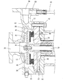
図3は超微細気泡発生装置の一例を示す断面図である。この例では、超微細気泡発生装置7は、直径と比較して高さの低い円筒状の筐体71と、該筐体71の内部に水平に設置されている上下2つの円盤74,75とで構成されている。筐体71の下部には気液混合物流入口72が設けられており、上部には気液混合物流出口73が設けられている。2つの円盤のうち下に位置する円盤74はドーナッツ状であり、筐体71の内部の底面に設置されている。2つの円盤のうち上に位置する円盤75は円盤74とほぼ同径の円板状であり、円盤74を覆うように設置されている。円盤74と円盤75の対向面周縁部の周方向には、送水ポンプ6により圧力がかけられた気液混合物を通過させて外方向に噴出させる環状スリットが形成されている。気液混合物の噴出方向は、気液混合物流入口から円盤74と円盤75とで区画される領域に流入する気液混合物の流入方向に対して直交する方向である。圧力がかけられた気液混合物が環状スリットを通過する際、超微細気泡が多数生成し、この超微細気泡を含んだ気液混合物(超微細気泡混合液)が気液混合物流出口73から流出し、膜モジュール11に供給される。図3中の矢印は気液混合物の流れを示す。気液混合物流出口73が筐体71の上部に設けられているため、気体が滞留せず、超微細気泡混合液がスムーズに膜モジュール6に供給される。このように、本発明では、超微細気泡発生装置はできる限り気体が滞留しない構造を有しているのが好ましい。
FIG. 3 is a cross-sectional view showing an example of an ultrafine bubble generator. In this example, the ultrafine
超微細気泡発生装置7では、例えば環状スリットの構造、気液混合物の環状スリットにおける通過速度、気体と液体の供給割合等を調整することにより、超微細気泡混合液中の(超)微細気泡の気泡径、気泡径分布、及び気泡の個数を制御することができる。気泡の個数、気泡径、気泡径の分布等は、前記のように、パーティクルカウンターを用いて測定することができる。
In the
環状スリットは、内径側から外径側に向かって間隙最小部77から拡大するように設けられた流路拡大部78を備えているのが好ましい。環状スリットがこのような構造を有すると、気液混合物が高速で通過して噴出することにより、流路間隙の変化によって、気液混合物中に超微細気泡が発生する。これは、気液混合物が内径側から外径側に向かって間隙最小部77から連続的に拡大する流路(流路拡大部78)を通過する際に、気液混合物の流速が変化して圧力が変化するためである。
It is preferable that the annular slit includes a flow
上記好ましい環状スリットの構造においては、少なくとも内径側から外径側に向かって間隙最小部77から拡大するように設けられた流路拡大部78を備えている限り特に限定されず、例えば、間隙最小部77の内径側に、間隙最小部に向かって連続的に流路が縮小する流路縮小部76を有していてもよい。また、環状スリットは、内径側から外径側に向かって段階的に流路断面積が増える構造、内径側から外径側に向かって段階的に流路断面積が減少する構造、内径側から外径側に向かって連続的に流路断面積が増える構造、内径側から外径側に向かって連続的に流路断面積が減少する構造を有していてもよい。本発明では、超微細気泡を効率よく発生させる観点から、環状スリットは、内径側から外径側に向かって間隙最小部から連続的に流路断面積が増える流路拡大部を備えることが好ましい。
The preferable structure of the annular slit is not particularly limited as long as it has the flow
環状スリットの流路拡大部78における拡がり角度(断面での拡がり角度)θ2は、超微細気泡発生効率の点から、流路縮小部76における縮小角度(断面での縮小角度)θ1より小さくする場合が多いが、θ2はθ1と等しいか又はそれより大きくてもよい。
When the expansion angle (expansion angle in the cross section) θ2 of the annular slit in the flow
上記のような構造を有する超微細気泡発生装置7を用いることにより、気泡径2〜50μmの気泡の個数(パーティクルカウンタで測定される個数)が、20〜30℃において、例えば100個/mL以上(好ましくは300個/mL以上、さらに好ましくは1000個/mL以上、特に2000個/mL以上)である超微細気泡含有原水を得ることができる。また、上記のような構造を有する超微細気泡発生装置7を用いた場合、気泡径2〜5μmの気泡の個数(パーティクルカウンタで測定される個数)が、20〜30℃において、例えば100個/mL以上(好ましくは300個/mL以上、さらに好ましくは1000個/mL以上、特に2000個/mL以上)である超微細気泡混合液を得ることができる。
By using the
上記の例では、送水ポンプと超微細気泡発生装置とが別個の機器、装置として用いられているが、送水ポンプと超微細気泡発生装置、あるいは前記の2装置とエア吸引口とは一体化していてもよい。以下に、送水ポンプと超微細気泡発生装置とが一体化した装置について、説明する。なお、下記の図4〜図8で示される送水ポンプと超微細気泡発生装置とが一体化した装置を用いた場合も、上記と同様、20〜30℃において、例えば100個/mL以上(好ましくは300個/mL以上、さらに好ましくは1000個/mL以上、特に2000個/mL以上)である超微細気泡含有原水を得ることができ、気泡径2〜5μmの気泡の個数(パーティクルカウンタで測定される個数)が、20〜30℃において、例えば100個/mL以上(好ましくは300個/mL以上、さらに好ましくは1000個/mL以上、特に2000個/mL以上)である超微細気泡混合液を得ることができる。 In the above example, the water pump and the ultrafine bubble generating device are used as separate devices and devices, but the water pump and the ultrafine bubble generating device, or the two devices and the air suction port are integrated. May be. Below, the apparatus with which the water pump and the ultrafine bubble generator were integrated is demonstrated. In addition, also when using the apparatus with which the water pump shown in the following FIGS. 4-8 and the ultrafine bubble generating apparatus were integrated, at 20-30 degreeC similarly to the above, for example, 100 pieces / mL or more (preferably Can obtain raw water containing ultrafine bubbles of 300 / mL or more, more preferably 1000 / mL or more, particularly 2000 / mL or more, and the number of bubbles having a bubble diameter of 2 to 5 μm (measured with a particle counter). The number of particles) is, for example, 100 / mL or more (preferably 300 / mL or more, more preferably 1000 / mL or more, particularly 2000 / mL or more) at 20 to 30 ° C. Can be obtained.
図4は、送水ポンプと超微細気泡発生装置とが一体化した装置(以下、「超微細気泡発生ポンプ」或いは「超微細気泡発生装置内蔵送水ポンプ」と称する場合がある)の一例を示す部分断面図(送液分散部の断面図)である。図5は、図4の送液ポンプと超微細気泡発生装置とが一体化した装置の収納室の部分拡大図(断面図)である。 FIG. 4 shows an example of an apparatus in which a water pump and an ultrafine bubble generator are integrated (hereinafter, sometimes referred to as “ultrafine bubble generator pump” or “superfine bubble generator built-in water pump”). It is sectional drawing (sectional drawing of a liquid feeding dispersion | distribution part). FIG. 5 is a partially enlarged view (cross-sectional view) of a storage chamber of a device in which the liquid feed pump and the ultrafine bubble generating device of FIG. 4 are integrated.
この超微細気泡発生ポンプは、液体中に供給された気体を超微細気泡として分散させるものであり、キャンドモータと送液分散部とを備えている。図4ではキャンドモータ部は省略されている。30はキャンドモータの回転軸であり、31は前部軸受箱(前部の軸受収納固定部位)である。
This ultrafine bubble generating pump disperses the gas supplied in the liquid as ultrafine bubbles, and includes a canned motor and a liquid feed dispersion unit. In FIG. 4, the canned motor portion is omitted.
筐体34は、前部軸受箱31にボルト42にて液密に締結固定されている。筐体34と前部軸受箱31は、収納室35を画定する。筐体34には、液体供給口39及び液体流出口38が設けられてる。液体供給口39は、キャンドモータの回転子の回転軸30の延在位置に設けられ、液体流出口38は、筐体34の回転軸30に対し交差する方向に位置する面に設けられている。
The
収納室35内には、インペラ(ポンプインペラ)43が収納される。インペラ43は、キャンドモータの回転軸30の先端にボルト44により締結される。図4に示すように、インペラ43は、クローズタイプの遠心インペラで構成され、インペラ本体部45内部に、インペラ本体部の一部を構成する円板の表面に送液用の遠心羽根46を備えた構成となっている。また、インペラ本体部45の裏面側には、循環羽根47が設けられている。循環羽根47は、遠心羽根46に比較して大径に構成されている。
An impeller (pump impeller) 43 is stored in the
インペラ43は、収納室35内において、前部軸受箱31のインペラ本体部45の対向面32とインペラ43との間に隙間が生じるように構成されている。インペラ本体部45によって、収納室35内は、送液空間36と循環空間37に区画される。送液空間36は、インペラ43の遠心羽根46によって、収納室35内の流体を液体流出口38側に搬送し、循環空間37では、供給された液体が、インペラ43の遠心羽根46及び循環羽根47によって生じた圧力差によって、インペラ本体部45の遠心方向及び求心方向に循環する。
The
前部軸受箱31のインペラ本体部45の対向面32とインペラ43との間の隙間には、分散部48が設けられる。分散部48は、前部軸受箱31の対向面32に当接して配置される。分散部48は、図5に示すように、2枚の円盤49,50で構成された分散部本体を備え、これら円盤49,50間には、円盤49,50の(ほぼ)全周にわたって分散流路51(環状スリット)が形成されている。
A
2枚の円盤49,50がそれぞれ対向する側の対向面には、図5に示すように、内径側から外径側に向かって拡開するようにテーパー部が対向して形成されており、流路51には、外径側から内径側に向かうに従って流路51の間隙が縮小していく流路縮小部51aが設けられる。また、この流路縮小部51aの内径側で流路51の隙間が外径側から内径側に向かうに従って拡大していく流路拡大部51bが形成され、これら流路縮小部51aと流路拡大部51bとの間に流路51の間隙が最も小さくなる間隙最小部51cが設けられている。このように、環状スリットは、外径側から内径側に向かって間隙最小部から拡大するように設けられた流路拡大部を備えているのも好ましい。
As shown in FIG. 5, taper portions are formed to face each other so that the two
前部軸受箱31を貫通する管路として設けられた気体供給流路40は、循環空間37の回転軸30の近接位置に開口する。
The gas
次に、図4、図5を用いて超微細気泡発生ポンプの動作を説明する。 Next, the operation of the ultrafine bubble generating pump will be described with reference to FIGS.
キャンドモータの回転軸30が回転すると、インペラ43も一体に回転し、液体を液体供給口39より取り入れる。インペラ43が回転することにより、液体が回転軸から遠心方向に送られ、一部が液体流出口38から流出する。
When the
インペラ43の回転により収納室35内において圧力分布が生じる。圧力分布は、回転軸30から離れるにつれて圧力が高くなり、図5に示すように、回転軸30から遠い側の領域A2の方が、回転軸30に近い側の領域A1よりも高圧になる。
A pressure distribution is generated in the
液体流出口38から流出しなかった液体は、インペラ43の循環空間37へ移動する。循環空間37では、気体供給流路40から取り込まれた空気と液体とが存在している。循環空間37の圧力は、回転軸30近傍の流体の領域A3の圧力よりも高いため流体は回転軸に近づくように移動する。このとき、気液混合物は、分散部48の分散流路51に設けられた流路縮小部51aおよび流路拡大部51bを順に通過して回転軸30に近づく方向に移動する。そして、気液混合物が流路縮小部51aを経て流路拡大部51bを通るとき、流路隙間の変化により気液混合物は流速が変化して圧力が変化し、気体が微細化され、超微細気泡が発生する。すなわち、ポンプのインペラ43での加圧後において、超微細気泡が発生する。
The liquid that has not flowed out from the
この気体微細化は、主として、液体の流速、気体の量、間隙最小部51cおよび流路拡大部51bの隙間寸法などによって決定される。例えば、気体の流速がある閾値以下であると、気泡の径が小さくならず十分な微細化が行われない。この場合、微細化される気泡の径は、主として、間隙最小部51cおよび流路拡大部51bの隙間寸法によって調整することができる。一方、液体の流速が閾値以上になると、気泡の径は小さくなって十分な微細化が行われる。分散流路51に設けられた流路拡大部51bがベンチュリ管と同様の効果を呈し、気体を伴った液体が分散部48の流路51内を通過することにより、気体を微細化することができる。分散流路(環状スリット)51の流路拡大部51bにおける拡がり角度(断面での拡がり角度)は、超微細気泡発生効率の点から、流路縮小部51aにおける縮小角度(断面での縮小角度)より小さくすることが多いが、前記拡がり角度は前記縮小角度と同じか又はそれより大きくてもよい。
This gas refinement is mainly determined by the flow rate of the liquid, the amount of gas, the gap size of the gap
インペラ本体部45の裏面側に設けられた循環羽根47は、放射流を発生させ、循環空間37内の気液分散流体を回転軸30側から遠心方向に移動させる。上記の通り、循環空間37内の回転軸近傍には、分散部48を通過して微細化された気液分散流体が存在しているため、この流体が回転軸30側から遠心方向に移動する。
The
また、循環羽根47の回転により、回転軸30に近傍の領域A3と循環羽根47の外側領域A4における流体の圧力が高くなるため、インペラ本体部45の循環空間37内の流体が遠心方向及び求心方向へ循環流動する。また、循環羽根の回転による遠心圧力場の形成により、気体供給流路40の出口は負圧になり、空気の自吸が促進される。
Further, the rotation of the
なお、本実施形態では、循環空間37内の流体の循環を促進するため、分散部48のインペラに近い側に設けられている円盤50には、回転軸側へ伸びる仕切り部50aが設けられている。円盤50によって、循環空間37内を仕切ることにより(37a、37b)、仕切り部50aを含む円盤50とインペラの本体部に対する対向面との空間、すなわち、分散流路51では、流体は求心方向へ移動しやすくなり、また、循環羽根47が位置するインペラの本体部45と円盤50との空間では、流体が遠心方向へ移動しやすくなる。このような構成を採用することにより、循環空間37内の流体の循環が促進され、また、流体が分散部48をより効率よく通過することとなるため、超微細気泡の発生を促進することができる。
In the present embodiment, in order to promote the circulation of the fluid in the
本実施形態にかかる超微細気泡発生ポンプは、収納室35内で遠心羽根46によって加圧された流体の一部が遠心羽根46の背後で循環流を起こす機構を有している。また、循環流路に空気を自吸させることができ、その自給させた空気を遠心羽根46の流れに合流させて、液体流出口38から流出させることができる。また、循環流の途中に分散部を備え、気泡の微細化を行うことができるため、液体の搬送と微細気泡の生成とを1つの装置で行うことができる。また、収納室35内に循環羽根47を備えることで、加圧条件下での使用であっても、差圧を発生させることができ、気泡の微細化を行うことができる。
The ultrafine bubble generating pump according to the present embodiment has a mechanism in which a part of the fluid pressurized by the
なお、上記の例では、循環羽根47が2つの円盤49,50で区画された領域の外側に設けられているが、循環羽根47を2つの円盤49,50で区画された領域の内側に設けるとともに、2つの円盤49,50で区画された領域内に流体が流入する流路を設けることもできる。このような実施形態では、上記の例とは逆に、2つの円盤49,50で区画された領域内に流入した流体(ポンプのインペラ43で加圧された流体)が分散流路(環状スリット)を、流路縮小部、間隙最小部、流路拡大部の順に通過して、前記領域の外側に(遠心方向に)噴出し、超微細気泡が発生する。
In the above example, the
また、上記の例では、分散部48がインペラ43の近傍に設けられているが、インペラ43で加圧された後に気液混合物中に超微細気泡を発生させる(例えば、環状スリットを通過させることにより)機構を有する限り、分散部48はインペラ43から離隔した位置に設けられていてもよい。
In the above example, the
図6は本発明の方法で使用される送水ポンプと超微細気泡発生装置とが一体化した装置(超微細気泡発生ポンプ;超微細気泡発生装置内蔵送水ポンプ)の他の例を示す断面図である。図7は、図6の超微細気泡発生装置内蔵送水ポンプのポンプ部及び分散部(超微細気泡発生部)の部分拡大図(断面図)である。図6、図7において、矢印は液体、気液混合物の流れ方向を示す。図6において、「MB発生部」とは分散部(超微細気泡発生部)を意味する。 FIG. 6 is a cross-sectional view showing another example of a device in which a water pump and an ultrafine bubble generator used in the method of the present invention are integrated (ultrafine bubble generator pump; water pump with a built-in ultrafine bubble generator). is there. FIG. 7 is a partially enlarged view (cross-sectional view) of a pump part and a dispersion part (ultrafine bubble generation part) of the water pump with a built-in ultrafine bubble generation apparatus of FIG. 6 and 7, arrows indicate the flow direction of the liquid and gas-liquid mixture. In FIG. 6, “MB generation part” means a dispersion part (ultrafine bubble generation part).
この超微細気泡発生ポンプは、液体中に供給された気体を超微細気泡として分散させるものであり、モータ部(キャンドモータ部)とポンプ部と超微細気泡発生部とからなっている。230はキャンドモータの回転軸である。
This ultrafine bubble generating pump disperses the gas supplied in the liquid as ultrafine bubbles, and includes a motor part (canned motor part), a pump part, and an ultrafine bubble generating part.
ポンプ部には、液体供給口239、気体供給流路240及びエア抜きバルブ260が設けられてる。液体供給口239は、キャンドモータの回転子の回転軸230の延在位置に設けられ、エア抜きバルブ260は、回転軸230に対し交差する方向に位置する面に設けられている。259はバルブである。
The pump unit is provided with a
ポンプ部内には、インペラ(ポンプインペラ)243が収納される。インペラ243は、キャンドモータの回転軸230の先端に取り付けられている。図6、図7に示すように、インペラ243は、クローズタイプの遠心インペラで構成され、インペラ本体部内部に、インペラ本体部の一部を構成する円板の表面に送液用の遠心羽根246を備えた構成となっている。インペラ243の高速回転により、液体供給口239付近は負圧となり、空気が気体供給流路240から自吸される。
An impeller (pump impeller) 243 is accommodated in the pump unit. The
液体供給口239及び気体供給流路240からポンプ部内に流入した液体と気体(空気)は遠心羽根246により混合され、遠心方向に移行した後、ポンプ部とモータ部の間に設けられた超微細気泡発生部に流入する。超微細気泡発生部は、図7に示すように、2枚の円盤249,250で構成された分散部本体を備え、これら円盤249,250間には、その周縁部において、円盤249,250の(ほぼ)全周にわたって分散流路251(環状スリット)が形成されている。また、2枚の円盤249,250で区画された領域内において、回転軸230に回転体252が設けられており、回転体252は円盤252aと複数の遠心翼252bにより構成されている。
The liquid and gas (air) that flowed into the pump unit from the
2枚の円盤249,250がそれぞれ対向する側の対向面には、図7に示すように、内径側から外径側に向かって拡開するようにテーパー部が対向して形成されており、流路251には、内径側から外径側に向かうに従って流路251の間隙が縮小していく流路縮小部251aが設けられる。また、この流路縮小部251aの外径側で流路251の隙間が内径側から外径側に向かうに従って拡大していく流路拡大部251bが形成され、これら流路縮小部251aと流路拡大部251bとの間に流路251の間隙が最も小さくなる間隙最小部251cが設けられている。
As shown in FIG. 7, taper portions are formed to face each other on the facing surfaces of the two
次に、図6、図7を用いて超微細気泡発生ポンプの動作を説明する。 Next, the operation of the ultrafine bubble generating pump will be described with reference to FIGS.
キャンドモータの回転軸230が回転すると、インペラ243も一体に回転し、液体を液体供給口239から、気体(空気)を気体供給流路240から取り入れる。インペラ243が回転することにより、気液混合物が回転軸から遠心方向に送られ、さらに超微細気泡発生部に移動する。
When the
超微細気泡発生部では、回転軸230の高速回転により、気液混合物は2枚の円盤249,250で区画された領域内に流入し、回転体252の遠心翼252bの回転により、分散部248の分散流路251に設けられた流路縮小部251aおよび流路拡大部251bを順に通過する。そして、気液混合物が流路縮小部251aを経て流路拡大部251bを通るとき、流路隙間の変化により気液混合物は流速が変化して圧力が変化し、気体が微細化され、超微細気泡が発生する。すなわち、ポンプのインペラ243での加圧後において、超微細気泡が発生する。
In the ultrafine bubble generating unit, the gas-liquid mixture flows into the region defined by the two
この気体微細化は、前述したように、主として、液体の流速、気体の量、間隙最小部251cおよび流路拡大部251bの隙間寸法などによって決定される。分散流路(環状スリット)251の流路拡大部251bにおける拡がり角度(断面での拡がり角度)は、超微細気泡発生効率の点から、流路縮小部251aにおける縮小角度(断面での縮小角度)より小さくすることが多いが、前記拡がり角度は前記縮小角度と同じか又はそれより大きくてもよい。
As described above, this gas refinement is mainly determined by the flow rate of the liquid, the amount of gas, the gap size of the gap
図8は本発明の方法で使用される送水ポンプと超微細気泡発生装置とが一体化した装置(超微細気泡発生ポンプ;超微細気泡発生装置内蔵送水ポンプ)のさらに他の例を示す断面図である。図8において、矢印は液体、気液混合物の流れ方向を示す。また、「MB発生部」とは分散部(超微細気泡発生部)を意味する。 FIG. 8 is a cross-sectional view showing still another example of a device in which a water pump and an ultrafine bubble generator used in the method of the present invention are integrated (superfine bubble generator pump; water pump with a built-in ultrafine bubble generator). It is. In FIG. 8, the arrows indicate the flow direction of the liquid and gas-liquid mixture. Further, “MB generation part” means a dispersion part (ultrafine bubble generation part).
この超微細気泡発生ポンプは、液体中に供給された気体を超微細気泡として分散させるものであり、モータ部(キャンドモータ部)とポンプ部と超微細気泡発生部とからなっている。330はキャンドモータの回転軸である。ポンプ部と超微細気泡発生部はモータ部を挟んでその両側に設けられている。
This ultrafine bubble generating pump disperses the gas supplied in the liquid as ultrafine bubbles, and includes a motor part (canned motor part), a pump part, and an ultrafine bubble generating part.
ポンプ部には、液体供給口339、気体供給流路340が設けられてる。液体供給口339は、キャンドモータの回転子の回転軸330の延在位置に設けられいる。359はバルブである。
A
ポンプ部内には、インペラ(ポンプインペラ)343が収納される。インペラ343は、キャンドモータの回転軸330の先端に取り付けられている。図8に示すように、インペラ343は、クローズタイプの遠心インペラで構成され、インペラ本体部内部に、インペラ本体部の一部を構成する円板の表面に送液用の遠心羽根346を備えた構成となっている。インペラ343の高速回転により、液体供給口339付近は負圧となり、空気が気体供給流路340から自吸される。
An impeller (pump impeller) 343 is accommodated in the pump unit. The
液体供給口339及び気体供給流路340からポンプ部内に流入した液体と気体(空気)は遠心羽根346により混合され、その一部はキャンドモータの冷却用として用いられ(冷却ラインを循環した後、ポンプ部に戻る)、残りは遠心方向に移行した後、中間配管370を通って超微細気泡発生部に流入する。超微細気泡発生部は、図8に示すように、2枚の円盤349,350で構成された分散部本体を備え、これら円盤349,350間には、その周縁部において、円盤349,350の(ほぼ)全周にわたって分散流路351(環状スリット)が形成されている。また、2枚の円盤349,350で区画された領域内において、回転軸330に回転体352が設けられており、回転体352は円盤352aと複数の遠心翼352bにより構成されている。
The liquid and gas (air) that flowed into the pump unit from the
2枚の円盤349,350がそれぞれ対向する側の対向面には、図8に示すように、内径側から外径側に向かって拡開するようにテーパー部が対向して形成されており、流路351には、内径側から外径側に向かうに従って流路351の間隙が縮小していく流路縮小部351aが設けられる。また、この流路縮小部351aの外径側で流路351の隙間が内径側から外径側に向かうに従って拡大していく流路拡大部351bが形成され、これら流路縮小部351aと流路拡大部351bとの間に流路351の間隙が最も小さくなる間隙最小部351cが設けられている。なお、超微細気泡発生部には、エア抜きバルブ360が、回転軸330に対し交差する方向に位置する面に設けられている。
As shown in FIG. 8, tapered portions are formed so as to face each other so as to expand from the inner diameter side toward the outer diameter side on the facing surface on the side where the two
次に、図8を用いて超微細気泡発生ポンプの動作を説明する。 Next, the operation of the ultrafine bubble generating pump will be described with reference to FIG.
キャンドモータの回転軸330が回転すると、インペラ343も一体に回転し、液体を液体供給口339から、気体(空気)を気体供給流路340から取り入れる。インペラ343が回転することにより、気液混合物が回転軸から遠心方向に送られ、中間配管370を通ってMB発生部に移動する。
When the
MB発生部では、回転軸330の高速回転により、気液混合物は2枚の円盤349,350で区画された領域内に流入し、回転体352の遠心翼352bの回転により、分散部348の分散流路351に設けられた流路縮小部351aおよび流路拡大部351bを順に通過する。そして、気液混合物が流路縮小部351aを経て流路拡大部351bを通るとき、流路隙間の変化により気液混合物は流速が変化して圧力が変化し、気体が微細化され、超微細気泡が発生する。すなわち、ポンプのインペラ343での加圧後において、超微細気泡が発生する。
In the MB generator, the gas-liquid mixture flows into the region defined by the two
この気体微細化は、前述したように、主として、液体の流速、気体の量、間隙最小部351cおよび流路拡大部351bの隙間寸法などによって決定される。分散流路(環状スリット)351の流路拡大部351bにおける拡がり角度(断面での拡がり角度)は、超微細気泡発生効率の点から、流路縮小部351aにおける縮小角度(断面での縮小角度)より小さいのが好ましい。
As described above, this gas refinement is mainly determined by the flow rate of the liquid, the amount of gas, the gap size of the gap
図2は本発明の水浄化システムの運転方法の他の例を示す概略説明図(概略フロー図)である。なお、図中、108はバルブ、109は流量調整バルブ、128は圧力計、129は流量計を示す。 FIG. 2 is a schematic explanatory diagram (schematic flow diagram) showing another example of the operation method of the water purification system of the present invention. In the figure, 108 is a valve, 109 is a flow rate adjusting valve, 128 is a pressure gauge, and 129 is a flow meter.
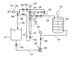
原水供給ライン101から原水タンク103に送水貯留された原水(被処理水)は、原水供給ライン104から超微細気泡発生ポンプ(送水ポンプと超微細気泡発生装置とが一体化した装置)106により膜モジュール(濾過器)111に供給される。超微細気泡発生ポンプ106には空気を原水中に導入するエア吸引口(気体供給手段;空気供給口)105が設けられている。エア吸引口105はポンプインペラによる加圧前、加圧後の何れに設けられていてもよいが、自吸できる点からは、ポンプインペラによる加圧前に設けられているのが好ましい。原水供給ライン104は複数設けてもよい。原水の夾雑物を除去する目的で適宜な位置にプレフィルターを取り付けてもよい。超微細気泡発生ポンプ106としては、例えば、前記したものを使用できる。
The raw water (treated water) stored and fed from the raw
超微細気泡発生ポンプ106により原水中に超微細気泡が多数生成する。超微細気泡発生ポンプ106で調製された超微細気泡含有原水は、バルブV−4及び流量調整バルブFCVを経て、縦置きに設置された膜モジュール(濾過器)111の側部に設けられた超微細気泡含有原水供給口110から膜モジュール(濾過器)111に供給される。
A large number of ultrafine bubbles are generated in the raw water by the ultrafine
膜モジュール(濾過器)111は、円筒状のハウジング内に円筒状の濾過フィルター126が収容されたものであり、超微細気泡含有原水供給口110、濾過水取り出し口118、濃縮液排水口112を有している。超微細気泡含有原水供給口、濾過水取り出し口は少なくとも1つ備えていればよい。濾過フィルター126には焼結金網製円筒型エレメント等のエレメントが収容されている。
The membrane module (filter) 111 includes a
膜モジュール(濾過器)111において、所定条件下で膜濾過された濾過水は、濾過水取り出し口118、バルブV−6を経て、濾過水及び濃縮液排水ライン116より回収される。
In the membrane module (filter) 111, the filtered water that has been membrane filtered under a predetermined condition is recovered from the filtered water and the concentrated
膜濾過運転時には、濾過能力を維持するために、定期的に逆圧洗浄を行うことが望ましい。逆圧洗浄は、例えば、膜濾過運転の状態で、バルブV−6を閉止することで濾過フィルター内部を昇圧し、昇圧完了後、バルブV−4を閉止し、濾過フィルター126を加圧状態のまま、密閉した後、バルブV−7、V−8を一気に開け、フィルター内部の圧力を一次側(濃縮液排水側)方向へ脱圧し、エレメントを洗浄し、洗浄液(濃縮液を含む)を濃縮液排水口112から濃縮液排水ライン113を通じ、バルブV−8を経て、濾過水及び濃縮液排水ライン116を通じて排出する。このように、膜濾過運転において定期的に逆圧洗浄を行うことで、フィルターエレメントの目詰まりを抑制しながら濾過運転を長期間継続できる。
During the membrane filtration operation, it is desirable to periodically perform back-pressure washing in order to maintain the filtration capacity. In the reverse pressure cleaning, for example, in the state of the membrane filtration operation, the pressure inside the filtration filter is increased by closing the valve V-6, and after completion of the pressure increase, the valve V-4 is closed and the
膜濾過運転を長期間行うと、フィルター内部に濁質が蓄積されるため、そのような濁質の定期的な排出が必要となる。その場合には、定期的に、濾過水をバルブV−9側より濾過水ライン120を通じて濾過水タンク121へ貯留した後、バルブV−1とV−2を切り替え、バルブV−7,V−8を開の状態にして、濾過水を超微細気泡発生ポンプ106を用いて、濾過フィルター126へ送液することで、フィルター内部の一次側(濃縮液側)の水を更新して、フィルター内部の原水の過剰な濁質濃度上昇を防止する。濾過水を濾過フィルター126へ送液する経路については、V−4側から送り込むフラッシング方式とV−5側から送り込む逆流方式の2つの方式を使い分けることができる。
When the membrane filtration operation is performed for a long period of time, turbidity accumulates inside the filter, and thus it is necessary to periodically discharge such turbidity. In that case, the filtered water is periodically stored in the
図11は本発明の水浄化システムの運転方法のさらに他の例を示す概略説明図(概略フロー図)である。なお、図中、108はバルブ、109は流量調整バルブ、128は圧力計、129は流量計を示す。 FIG. 11 is a schematic explanatory diagram (schematic flowchart) showing still another example of the operation method of the water purification system of the present invention. In the figure, 108 is a valve, 109 is a flow rate adjusting valve, 128 is a pressure gauge, and 129 is a flow meter.
この例は、前述した、清浄水及び/又は膜モジュールからの透過水(濾過水)を水供給ポンプによって加圧し、前記水供給ポンプでの加圧後であって膜モジュール供給前の清浄水及び/又は膜モジュールからの透過水(濾過水)中に超微細気泡を発生させるとともに、こうして得られる超微細気泡含有液を被洗浄機器又は装置の洗浄に使用し、得られた使用後の洗浄液を膜モジュールに供給して膜濾過を行い、水を清浄化する態様の一例である。
In this example, the above-described clean water and / or permeated water (filtered water) from the membrane module is pressurized by a water supply pump, and after the pressurization by the water supply pump and before the membrane module is supplied, In addition to generating ultrafine bubbles in the permeated water (filtered water) from the membrane module, the ultrafine bubble-containing liquid obtained in this way is used for cleaning the device or apparatus to be cleaned, and the obtained cleaning liquid after use is used. It is an example of the aspect which supplies to a membrane module, performs membrane filtration, and purifies water.
膜モジュール(濾過器)111からバルブV−6、V−9を経て、濾過水ライン120を通じて濾過水タンク121に貯留された濾過水は、バルブV−10を経て、濾過水循環ライン117から超微細気泡発生ポンプ(送水ポンプと超微細気泡発生装置とが一体化した装置)106により、バルブV−3からタンク供給液ライン132を通じて、被洗浄機器又は装置である撹拌機131付きのタンク130に供給される。超微細気泡発生ポンプ106には空気を原水中に導入するエア吸引口(気体供給手段;空気供給口)105が設けられている。エア吸引口105はポンプインペラによる加圧前、加圧後の何れに設けられていてもよいが、自吸できる点からは、ポンプインペラによる加圧前に設けられているのが好ましい。超微細気泡発生ポンプ106としては、例えば、前記したものを使用できる。
The filtrate stored in the
超微細気泡発生ポンプ106により原水中に超微細気泡が多数生成する。このため、タンク130に供給される洗浄液は気泡径の極めて小さい超微細気泡を含み、タンク130の微細な箇所の汚染に対しても優れた洗浄効果が発揮される。なお、前記濾過水の一部又は全部は清浄水で置き換えることができる。
A large number of ultrafine bubbles are generated in the raw water by the ultrafine
タンク洗浄後の液は膜モジュール供給液ライン133を通じて、バルブV−4及び流量調整バルブFCVを経て、縦置きに設置された膜モジュール(濾過器)111の側部に設けられた超微細気泡含有原水供給口110から膜モジュール(濾過器)111に供給される。
The liquid after washing the tank contains ultrafine bubbles provided on the side of the membrane module (filter) 111 installed vertically through the membrane module
膜モジュール(濾過器)111は、円筒状のハウジング内に円筒状の濾過フィルター126が収容されたものであり、超微細気泡含有原水供給口110、濾過水取り出し口118、濃縮液排水口112を有している。超微細気泡含有原水供給口、濾過水取り出し口は少なくとも1つ備えていればよい。濾過フィルター126には焼結金網製円筒型エレメント等のエレメントが収容されている。
The membrane module (filter) 111 includes a
膜モジュール(濾過器)111において、所定条件下で膜濾過された濾過水は、濾過水取り出し口118、バルブV−6、V−9を経て、濾過水ライン120を通じて濾過水タンク121に貯留される。
In the membrane module (filter) 111, the filtered water membrane-filtered under a predetermined condition is stored in the filtered
膜濾過運転時には、濾過能力を維持するために、定期的に逆圧洗浄を行うことが望ましい。逆圧洗浄は、例えば、膜濾過運転の状態で、バルブV−6を閉止することで濾過フィルター内部を昇圧し、昇圧完了後、バルブV−4を閉止し、濾過フィルター126を加圧状態のまま、密閉した後、バルブV−7、V−8を一気に開け、フィルター内部の圧力を一次側(濃縮液排水側)方向へ脱圧し、エレメントを洗浄し、洗浄液(濃縮液を含む)を濃縮液排水口112から濃縮液排水ライン113を通じ、バルブV−8を経て、濾過水及び濃縮液排水ライン116を通じて排出する。フィルター内部の急激な圧力降下が起こる際に、濾過装置内部(特に、濾過フィルターの濾材エレメントや分離膜に蓄積した堆積物の内部)にしみ込んだ液中に存在する超微細気泡が膨張し、堆積物が破砕する。これに加えて、原液側(一次側)より圧力降下が生じるため、濾過液側(二次側)の圧力も一次側へ逃げることから、濾過液の逆流が生じ、破砕された堆積物は濾材又は分離膜表面から流れに沿って引き離される。このため、膜表面の堆積物(タンク等の汚れ)が膜表面から効率よく且つ確実に剥離されることになる。
During the membrane filtration operation, it is desirable to periodically perform back-pressure washing in order to maintain the filtration capacity. In the reverse pressure cleaning, for example, in the state of the membrane filtration operation, the pressure inside the filtration filter is increased by closing the valve V-6, and after completion of the pressure increase, the valve V-4 is closed and the
上記方法によれば、超微細気泡を含む洗浄液でタンクを洗浄するので、超微細気泡の働きによりタンクの隅々まで清浄化できる。また、洗浄後の液(使用済みの洗浄液)は、濾過フィルターにより浄化され、浄化された濾過水はまた洗浄液として再利用される。さらに、濾過水を用いるので、ポンプが閉塞したりしない。また、上記の逆圧洗浄においては、超微細気泡の働きにより、濾過フィルターの詰まりを効果的に防止できる。このため、タンク等の機器又は装置の洗浄を極めて効率よく行うことができる。 According to the above method, since the tank is washed with the cleaning liquid containing the ultrafine bubbles, it is possible to clean the entire tank by the action of the ultrafine bubbles. Moreover, the liquid after cleaning (used cleaning liquid) is purified by a filtration filter, and the purified filtered water is also reused as a cleaning liquid. Furthermore, since filtered water is used, the pump is not blocked. Further, in the above-described back pressure cleaning, clogging of the filtration filter can be effectively prevented by the action of ultrafine bubbles. For this reason, it is possible to clean a device such as a tank or a device very efficiently.
なお、本発明の水浄化システムの運転方法は、使用前の膜モジュールの前処理にも適用できる。すなわち、上記水浄化システムの運転方法において、原水の代わりに透過水等の浄化された水を水供給ポンプにより膜モジュールに供給し、水供給ポンプでの加圧後に、超微細気泡を発生させつつ、該清浄水を加圧濾過することにより、膜表面の接触角が変化し(親水化し)して、汚れにくい膜モジュールを得ることができる。 In addition, the operating method of the water purification system of this invention is applicable also to the pre-processing of the membrane module before use. That is, in the operation method of the water purification system, purified water such as permeated water is supplied to the membrane module by the water supply pump instead of the raw water, and after the pressurization by the water supply pump, ultrafine bubbles are generated. By filtering the clean water under pressure, the contact angle of the membrane surface is changed (hydrophilized), and a membrane module that is not easily contaminated can be obtained.
以下に実施例を挙げて本発明をさらに具体的に説明するが、本発明はこれらの実施例によって限定されるものではない。 The present invention will be described more specifically with reference to the following examples. However, the present invention is not limited to these examples.
実施例1
図1に示す水浄化システム(設備)により、膜濾過運転を行った。原水(揖保川の河川水)を、原水供給ライン1を通じ、プレフィルター2(オートストレーナー)を経て原水タンク3に送液した。プレフィルター2として、セントラルフィルター工業(株)製の製品名「ジュラクリーン」(濾過精度100μm)を用いた。原水タンク3の原水を原水供給ライン4を通じ、送水ポンプ6を用いて、送水ポンプ6の下流側にて超微細気泡を発生させつつ、縦置きに設置された中空糸膜モジュール11[UF膜、分画分子量:150000(孔径0.01μm)、膜材質:酢酸セルロース、膜形状:内圧型中空系、膜内径:0.8mm、膜外径:1.3mm、有効膜面積:5m2、モジュール外形寸法:1126mm、純水透過性能:3000L/hr・0.1MPa・25℃]に供給した。ラインの途中、送水ポンプ6の上流側に設けたエア吸引口5から空気を0.13L/min0(標準状態)の流量で原水中に混合させ、空気を混合させた原水を送水ポンプ6により該送水ポンプ6の下流側に設けられた超微細気泡発生装置7に供給し、超微細気泡発生装置7で超微細気泡含有原水を調製した。送水ポンプ6の吐出側の圧力(濾過圧力)は0.05MPa(ゲージ圧)であり、送水ポンプ6のサクション側の圧力は−0.01MPa(ゲージ圧)であった。濾過方式は内圧式のクロスフロー方式(クロスフロー速度:0.05m/s)である。
Example 1
The membrane filtration operation was performed by the water purification system (equipment) shown in FIG. Raw water (Ribo River water) was fed through the raw
超微細気泡発生装置7としては、図3に示されるような、上下にそれぞれ気液混合物流出口73及び気液混合物流入口72を備えた円筒状の筐体71と、該筐体71の内部に水平に設置されている上下2つの円盤74,75とで構成され、2つの円盤の対向面周縁部に周方向に設けられ、筐体71の内部の気液混合物を通過させて噴出させることにより気液混合物中に超微細気泡を発生させる環状スリットが形成されている装置を用いた。
As shown in FIG. 3, the ultrafine
各部位の寸法は以下の通りである。筐体71の直径:208.3mmφ、円盤75の直径:198mmφ、環状スリットの間隙最小部77のギャップ:0.2mm、気液混合液流入口72及び気液混合液流出口73の直径:38.6mmφ、環状スリットの流路拡大部78における拡がり角度(断面での拡がり角度)θ2:5°、環状スリットの流路縮小部76における縮小角度(断面での縮小角度)θ1:90°である。
The dimensions of each part are as follows. Diameter of housing 71: 208.3 mmφ, diameter of disk 75: 198 mmφ, gap of gap slit minimum portion 77: 0.2 mm, diameter of gas / liquid mixture inlet 72 and gas / liquid mixture outlet 73: 38 .6 mmφ, an expansion angle (expansion angle in the cross section) θ2: 5 ° in the annular slit flow
中空糸膜モジュール11において加圧膜濾過された透過水は、透過水ライン20を通じて透過水タンク21に送液し貯水した。濃縮液は運転開始より23日まではライン16を通じて全量排水し、それ以降は濃縮循環水ライン17を通じて送水ポンプ6に循環した。この際、透過水に次亜塩素酸ナトリウムを注入して有効塩素濃度3〜5ppmに調整した次亜塩素酸ナトリウム水溶液を用いて、1時間おきに30秒間の逆洗を行った。23日経過後、濃縮液を全量循環するラインに切り替えて膜濾過運転を23日〜51日間行った。実フラックスの変化を測定し、20℃換算フラックス[m/日]の経日変化として図9に示す。なお、運転開始後7日まではフラックスを2.0〜2.5m/日の条件で運転を行った。運転開始後14日〜23日、および38日〜51日の間は、それぞれエア吸引口5からの空気供給を停止、および空気流量が若干不安定であった。いずれの場合も一定の空気量が供給されていなかったが、フラックスは若干低下したものの、急激な低下はなかった。51日経過した時点で、超微細気泡発生装置7を取り外し、短管(通常の配管)に取り替え、51日〜60日の間は超微細気泡が発生しない条件下で膜濾過運転を行った。60〜71日は運転を停止し、71日からは再度短管を超微細気泡発生装置7に取り替え、運転を続行した。
その結果、超微細気泡発生装置を稼働した場合には、フラックス2.5〜3.0m/dayという高水準を維持できた。超微細気泡発生装置を短管に取り替えた場合には、フラックスが急激に低下した。
The permeated water filtered through the pressure membrane in the hollow
As a result, when the ultrafine bubble generator was operated, a high level of flux of 2.5 to 3.0 m / day could be maintained. When the ultrafine bubble generator was replaced with a short tube, the flux decreased rapidly.
超微細気泡発生装置7稼働時(空気供給時)の微細気泡の発生個数をパーティクルカウンターで測定したところ、気泡径2〜50μmの気泡の個数は2000個/mL以上であった。
When the number of microbubbles generated when the
実施例2
図2に示す水浄化システム(設備)により、膜濾過運転を行った。濾過フィルター126として、SUS特殊焼結金網製円筒型エレメント(セントラルフィルター工業社製、商品名「PM−A−C65*40*250−GL」、濾材寸法Φ65/Φ40×250L、濾過面積0.05m2)を円筒状のハウジング内に充填したものを用いた。超微細気泡発生ポンプ106として図8に示すポンプを用いた。また、原水として、水に生化学用カオリン(和光純薬工業社製)(擬似汚泥)を100重量ppm添加したものを用いた。
(1)超微細気泡発生ポンプ106により超微細気泡を含有させた原水を、バルブV−4側から濾過フィルター内の特殊エレメントで濾過し、バルブV−6より濾過水を取得する(バルブV−2、V−5、V−7、V−8は閉)[濾過運転]。
(2)濾過運転の状態で、バルブV−6を閉止することで、濾過フィルター内部を昇圧する[加圧工程]。
(3)昇圧完了後、バルブV−4を閉止し、フィルターを加圧状態のまま、密閉した後、バルブV−7、V−8を一気に開け、フィルター内部の圧力を一次側(濃縮液排水側)方向へ脱圧し、特殊エレメント洗浄を行う[脱圧工程〜復帰]。
上記(1)〜(3)の操作を繰り返すことで、膜濾過運転を行った。上記(1)〜(3)までの運転の1サイクルを3分とした。また、比較のため、超微細気泡発生ポンプ106にエア吸引口105からエアを供給しないこと以外は同様にして膜濾過運転を行った(超微細気泡を含有しない原水を濾過フィルターに供給した例)。
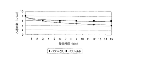
超微細気泡を添加した場合と添加しなかった場合のそれぞれについて、濾過流量と経過時間の関係を示すグラフを図10に示した。図10において、バブルありとは超微細気泡を添加した場合をいい、バブルなしとは超微細気泡を添加しなかった場合をいう。
濾過流量の測定値は、1サイクル終了時毎に実施する脱圧工程後の運転再開直後の流量を面積流量計で読み取った値である。
図10に見られるように、運転初期の流量低下は何れの運転でも発生したが、その後の濾過流量の低下は、超微細気泡添加原水を用いた場合が、超微細気泡を添加しない原水を用いた場合と比較して軽微であり、且つ安定した運転がなされた。図10に示した経過時間範囲内で、スタート直後に発生する流量低下部分を除いた場合、超微細気泡添加原水を用いたときの濾過流量の低下率は約10%であった。これに対し、超微細気泡を添加しない原水を用いたときの濾過流量の低下率は約35%であった。
Example 2
Membrane filtration operation was performed by the water purification system (equipment) shown in FIG. As the
(1) The raw water containing ultrafine bubbles by the ultrafine
(2) The pressure inside the filtration filter is increased by closing the valve V-6 in the state of the filtration operation [pressure process].
(3) After completion of pressurization, valve V-4 is closed and the filter is sealed in a pressurized state, then valves V-7 and V-8 are opened at once, and the pressure inside the filter is changed to the primary side (concentrate drainage). Side) direction and perform special element cleaning [depressurization process-return].
The membrane filtration operation was performed by repeating the operations (1) to (3). One cycle of the above operations (1) to (3) was set to 3 minutes. For comparison, a membrane filtration operation was performed in the same manner except that air was not supplied from the
FIG. 10 shows a graph showing the relationship between the filtration flow rate and the elapsed time for each of the case where the ultrafine bubbles were added and the case where the ultrafine bubbles were not added. In FIG. 10, “with bubbles” refers to the case where ultrafine bubbles are added, and “without bubbles” refers to the case where no ultrafine bubbles are added.
The measured value of the filtration flow rate is a value obtained by reading the flow rate immediately after the restart of operation after the depressurization step performed at the end of each cycle with an area flow meter.
As seen in FIG. 10, the flow rate drop at the initial stage of operation occurred in any operation, but the subsequent reduction of the filtration flow rate was performed using raw water without adding ultrafine bubbles when using ultrafine bubble added raw water. Compared with the case where it was, the operation was light and stable. In the elapsed time range shown in FIG. 10, when the flow rate reduction portion generated immediately after the start was removed, the reduction rate of the filtration flow rate when using the ultrafine bubble added raw water was about 10%. On the other hand, the rate of decrease in the filtration flow rate when using raw water without adding ultrafine bubbles was about 35%.
1,101 原水供給ライン
2 プレフィルター
3,103 原水タンク
4,104 原水供給ライン
5,105 エア吸引口
6 送水ポンプ(水供給ポンプ)
7 超微細気泡発生装置
8,108 バルブ
9 バルブ
10,110 超微細気泡含有原水供給口
11 膜モジュール
12,112 濃縮液排出口
13 逆圧洗浄排水ライン
14 バルブ
15a,15b バルブ
16 排水ライン
17 濃縮循環水ライン
18 透過水取り出し口
19 バルブ
20 透過水ライン
21 透過水タンク
22 逆洗用ポンプ
23 次亜塩素酸ナトリウム水溶液タンク
24 薬液ポンプ
25 逆圧洗浄ライン
106 超微細気泡発生ポンプ
109 流量調整バルブ
111 膜モジュール(濾過器)
113 濃縮液排水ライン
116 濾過水及び濃縮液排水ライン
117 濾過水循環ライン
118 濾過水取り出し口
120 濾過水ライン
121 濾過水タンク
126 濾過フィルター
127 原水戻りライン
128 圧力計
129 流量計
130 タンク
131 撹拌機
132 タンク供給液ライン
133 膜モジュール供給液ライン
30,230,330 キャンドモータの回転軸
31 前部軸受箱
32 前部軸受箱のインペラ本体部45の対向面
33 潤滑液排出口
34 筐体
35 収納室
36 送液空間
37 循環空間
38,238,338 液体流出口
39,239,339 液体供給口
40,240,340 気体供給流路
41 潤滑液管路
42 ボルト
43,243,343 インペラ
44 ボルト
45 インペラ本体部
46,246,346 遠心羽根
47 循環羽根
48,248,348 分散部
49,249,349 円盤
50,250,350 円盤
50a 仕切り部
51,251,351 分散流路
51a,251a,351a 流路縮小部
51b,251b,351b 流路拡大部
51c,251c,351c 間隙最小部
259,359 バルブ
260,360 エア抜きバルブ
370 中間配管
71 筐体
72 気液混合物流入口
73 気液混合物流出口
74 円盤
75 円盤
76 流路縮小部
77 間隙最小部
78 流路拡大部
1,101 Raw
7 Ultra
113
Claims (14)
Priority Applications (1)
| Application Number | Priority Date | Filing Date | Title |
|---|---|---|---|
| JP2010136494A JP2011083764A (en) | 2009-09-18 | 2010-06-15 | Method for operating water purification system and water purification system |
Applications Claiming Priority (2)
| Application Number | Priority Date | Filing Date | Title |
|---|---|---|---|
| JP2009218060 | 2009-09-18 | ||
| JP2010136494A JP2011083764A (en) | 2009-09-18 | 2010-06-15 | Method for operating water purification system and water purification system |
Publications (2)
| Publication Number | Publication Date |
|---|---|
| JP2011083764A true JP2011083764A (en) | 2011-04-28 |
| JP2011083764A5 JP2011083764A5 (en) | 2013-03-28 |
Family
ID=44077121
Family Applications (1)
| Application Number | Title | Priority Date | Filing Date |
|---|---|---|---|
| JP2010136494A Pending JP2011083764A (en) | 2009-09-18 | 2010-06-15 | Method for operating water purification system and water purification system |
Country Status (1)
| Country | Link |
|---|---|
| JP (1) | JP2011083764A (en) |
Cited By (9)
| Publication number | Priority date | Publication date | Assignee | Title |
|---|---|---|---|---|
| JP2014151304A (en) * | 2013-02-13 | 2014-08-25 | Mizuno Strainer Kogyo Kk | Back washing filtration apparatus and deposit removing method for filtration element |
| US9333464B1 (en) | 2014-10-22 | 2016-05-10 | Koch Membrane Systems, Inc. | Membrane module system with bundle enclosures and pulsed aeration and method of operation |
| JP2016203102A (en) * | 2015-04-23 | 2016-12-08 | 株式会社東芝 | Treatment system and treatment method |
| USD779631S1 (en) | 2015-08-10 | 2017-02-21 | Koch Membrane Systems, Inc. | Gasification device |
| KR20190071239A (en) * | 2017-12-14 | 2019-06-24 | 디에이치테크 주식회사 | Cassette type filter device |
| CN110342657A (en) * | 2018-04-02 | 2019-10-18 | 佛山市美的清湖净水设备有限公司 | Water purification system |
| KR102133422B1 (en) * | 2019-07-19 | 2020-07-13 | 회명솔레니스 (주) | Cleaning System for Filtering Membrane and Cleaning Method Thereof |
| WO2021076850A1 (en) * | 2019-10-17 | 2021-04-22 | Energy Harbors Corporation, Inc. | Desalination using pressure vessels |
| US11261107B2 (en) | 2017-08-31 | 2022-03-01 | Energy Internet Corporation | Desalination using pressure vessels |
Citations (5)
| Publication number | Priority date | Publication date | Assignee | Title |
|---|---|---|---|---|
| JP2007083108A (en) * | 2005-09-20 | 2007-04-05 | Sharp Corp | Method and apparatus for treating liquid |
| JP2008036518A (en) * | 2006-08-04 | 2008-02-21 | Sharp Corp | Water treatment method and apparatus |
| JP2009112947A (en) * | 2007-11-06 | 2009-05-28 | Shibaura Mechatronics Corp | Manufacturing apparatus and manufacturing method of processing liquid |
| JP2009148673A (en) * | 2007-12-19 | 2009-07-09 | Sekisui Chem Co Ltd | Membrane separation apparatus and desalination method |
| JP2010104902A (en) * | 2008-10-30 | 2010-05-13 | Daicen Membrane Systems Ltd | Operation method of water purification system, and water purification system |
-
2010
- 2010-06-15 JP JP2010136494A patent/JP2011083764A/en active Pending
Patent Citations (5)
| Publication number | Priority date | Publication date | Assignee | Title |
|---|---|---|---|---|
| JP2007083108A (en) * | 2005-09-20 | 2007-04-05 | Sharp Corp | Method and apparatus for treating liquid |
| JP2008036518A (en) * | 2006-08-04 | 2008-02-21 | Sharp Corp | Water treatment method and apparatus |
| JP2009112947A (en) * | 2007-11-06 | 2009-05-28 | Shibaura Mechatronics Corp | Manufacturing apparatus and manufacturing method of processing liquid |
| JP2009148673A (en) * | 2007-12-19 | 2009-07-09 | Sekisui Chem Co Ltd | Membrane separation apparatus and desalination method |
| JP2010104902A (en) * | 2008-10-30 | 2010-05-13 | Daicen Membrane Systems Ltd | Operation method of water purification system, and water purification system |
Cited By (13)
| Publication number | Priority date | Publication date | Assignee | Title |
|---|---|---|---|---|
| JP2014151304A (en) * | 2013-02-13 | 2014-08-25 | Mizuno Strainer Kogyo Kk | Back washing filtration apparatus and deposit removing method for filtration element |
| US9956530B2 (en) | 2014-10-22 | 2018-05-01 | Koch Membrane Systems, Inc. | Membrane module system with bundle enclosures and pulsed aeration and method of operation |
| US9333464B1 (en) | 2014-10-22 | 2016-05-10 | Koch Membrane Systems, Inc. | Membrane module system with bundle enclosures and pulsed aeration and method of operation |
| US10702831B2 (en) | 2014-10-22 | 2020-07-07 | Koch Separation Solutions, Inc. | Membrane module system with bundle enclosures and pulsed aeration and method of operation |
| JP2016203102A (en) * | 2015-04-23 | 2016-12-08 | 株式会社東芝 | Treatment system and treatment method |
| USD779631S1 (en) | 2015-08-10 | 2017-02-21 | Koch Membrane Systems, Inc. | Gasification device |
| USD779632S1 (en) | 2015-08-10 | 2017-02-21 | Koch Membrane Systems, Inc. | Bundle body |
| US11261107B2 (en) | 2017-08-31 | 2022-03-01 | Energy Internet Corporation | Desalination using pressure vessels |
| KR20190071239A (en) * | 2017-12-14 | 2019-06-24 | 디에이치테크 주식회사 | Cassette type filter device |
| KR102053401B1 (en) * | 2017-12-14 | 2019-12-09 | 디에이치테크 주식회사 | Cassette type filter device |
| CN110342657A (en) * | 2018-04-02 | 2019-10-18 | 佛山市美的清湖净水设备有限公司 | Water purification system |
| KR102133422B1 (en) * | 2019-07-19 | 2020-07-13 | 회명솔레니스 (주) | Cleaning System for Filtering Membrane and Cleaning Method Thereof |
| WO2021076850A1 (en) * | 2019-10-17 | 2021-04-22 | Energy Harbors Corporation, Inc. | Desalination using pressure vessels |
Similar Documents
| Publication | Publication Date | Title |
|---|---|---|
| JP5269749B2 (en) | Filtration device cleaning method | |
| JP2011083764A (en) | Method for operating water purification system and water purification system | |
| JP5068727B2 (en) | Operation method of water purification system and water purification system | |
| US20060065596A1 (en) | Membrane filter cleansing process | |
| US20210001273A1 (en) | Methods, systems, and compositions for delivery of nanobubbles in water treatment systems | |
| WO2013111826A1 (en) | Desalination method and desalination device | |
| US10954140B2 (en) | Apparatus for generating cavitation in a liquid | |
| WO2008053700A1 (en) | Method of desalting, apparatus for desalting, and bubble generator | |
| JP4698274B2 (en) | Filtration membrane cleaning method | |
| JP2014018782A (en) | System and method for cleaning filtration film of ballast water treatment | |
| JP5464836B2 (en) | Cleaning device and cleaning method | |
| JP6580338B2 (en) | Film processing apparatus and film processing method | |
| JP2011104549A (en) | Filtration system and filtration method | |
| JP5569217B2 (en) | Oxygen treatment boiler cleaning method and apparatus | |
| WO2012145787A1 (en) | Apparatus and method for reducing fouling and scaling in a fluid treatment system | |
| JP5801249B2 (en) | Desalination apparatus and desalination method | |
| KR20170033611A (en) | Water treatment system and water treatment method | |
| JP6530931B2 (en) | Method of desalting, method of cleaning demineralizer and demineralizer | |
| JP3838689B2 (en) | Water treatment system | |
| JP5401403B2 (en) | Solid recovery method | |
| JP3948593B2 (en) | Membrane cleaning method | |
| JP4943662B2 (en) | Operation method of membrane separator | |
| JPH11138163A (en) | Treatment of water in oil emulsion and device for treating water in oil emulsion | |
| Morales et al. | Desalination of Produced Water Using Reverse Osmosis | |
| US10876085B2 (en) | System and method for purification of drinking water, ethanol and alcohol beverages of impurities |
Legal Events
| Date | Code | Title | Description |
|---|---|---|---|
| A521 | Written amendment |
Effective date: 20130208 Free format text: JAPANESE INTERMEDIATE CODE: A523 |
|
| A621 | Written request for application examination |
Effective date: 20130208 Free format text: JAPANESE INTERMEDIATE CODE: A621 |
|
| A977 | Report on retrieval |
Effective date: 20130731 Free format text: JAPANESE INTERMEDIATE CODE: A971007 |
|
| A131 | Notification of reasons for refusal |
Free format text: JAPANESE INTERMEDIATE CODE: A131 Effective date: 20130820 |
|
| A521 | Written amendment |
Free format text: JAPANESE INTERMEDIATE CODE: A523 Effective date: 20131008 |
|
| A02 | Decision of refusal |
Free format text: JAPANESE INTERMEDIATE CODE: A02 Effective date: 20131105 |