JP2011069080A - Method for manufacturing wood plate-like building material - Google Patents
Method for manufacturing wood plate-like building material Download PDFInfo
- Publication number
- JP2011069080A JP2011069080A JP2009219941A JP2009219941A JP2011069080A JP 2011069080 A JP2011069080 A JP 2011069080A JP 2009219941 A JP2009219941 A JP 2009219941A JP 2009219941 A JP2009219941 A JP 2009219941A JP 2011069080 A JP2011069080 A JP 2011069080A
- Authority
- JP
- Japan
- Prior art keywords
- wood
- building material
- wooden
- veneer
- plate
- Prior art date
- Legal status (The legal status is an assumption and is not a legal conclusion. Google has not performed a legal analysis and makes no representation as to the accuracy of the status listed.)
- Granted
Links
Images
Landscapes
- Chemical And Physical Treatments For Wood And The Like (AREA)
- Floor Finish (AREA)
Abstract
【課題】木質板状建材の表層側に積層されるスライス単板を効率的に肉厚に加工し得るとともに、木質板状建材の意匠性を向上し得る木質板状建材の製造方法を提供する。
【解決手段】高圧高温水蒸気による加熱処理を施した木材1を、湿潤状態のままでスライスしてスライス単板13を作製し、このスライス単板を、木質基材12に貼着して積層体11を作製した後、前記積層体の表面11aに、溝部14及び面取り部15のうちの少なくともいずれか一方を、前記スライス単板の表面13aから下端14a,15aまでの深さDが、該スライス単板の厚さTの二倍以内となるように形成するようにした。
【選択図】図1The present invention provides a method for producing a wooden plate-shaped building material that can efficiently process a slice veneer laminated on the surface layer side of a wooden plate-shaped building material into a thick wall and can improve the design of the wooden plate-shaped building material. .
A timber 1 that has been heat-treated with high-pressure and high-temperature steam is sliced in a wet state to produce a slice veneer 13, and the slice veneer is bonded to a wooden substrate 12 to form a laminate. 11, at least one of the groove portion 14 and the chamfered portion 15 is formed on the surface 11a of the laminate, and the depth D from the surface 13a of the slice single plate to the lower ends 14a and 15a It was formed so as to be within twice the thickness T of the single plate.
[Selection] Figure 1
Description
本発明は、木質基材の表面にスライス単板を積層した木質板状建材の製造方法に関する。 The present invention relates to a method for manufacturing a wooden plate-shaped building material in which sliced single plates are laminated on the surface of a wooden substrate.
木質板状建材の木質感、意匠性を高めるには、無垢の木材を使用することが望ましいが、高価であるため、一般的には、合板やパーティクルボード、中密度繊維板(Medium Density Fiberboard、MDF)等の木質繊維板などの木質系材料を基材として、その表面に天然銘木をスライス加工して作製した表面化粧板(スライス単板)を貼り合わせた積層構造の木質板状建材が使用されている。 In order to improve the wood texture and design of woody plate-like building materials, it is desirable to use solid wood, but since it is expensive, it is generally plywood, particleboard, medium density fiberboard (Medium Density Fiberboard, MDF) and other wood-based materials such as wood fiberboard are used as the base material, and the surface is made of laminated wood-plate-like building materials with a surface decorative board (slice veneer) made by slicing natural name wood on the surface. Has been.
このような積層構造の木質板状建材の木質感を阻害しないように意匠性を向上させるには、表面の化粧板を厚くすることが好ましい。特に、木質板状建材の表面には、溝部(化粧溝)や面取り部が形成されることが多く、スライス単板の厚みが薄い場合には、これら溝部や面取り部において、下層側の基材が大きく露出してしまい、見栄えが悪いという問題があった。高濃度の塗料を厚塗りすることで、溝部や面取り部における基材の露出を防止することも考えられるが、表面のスライス単板の木質感が失われ、また、塗料が溜まり易い溝部において他の部位(表面)よりも濃色化する傾向があり、見栄えが悪くなるという問題があった。 In order to improve the design so as not to impair the wood texture of the wood-plate-like building material having such a laminated structure, it is preferable to make the decorative plate on the surface thick. In particular, grooves (decorative grooves) and chamfered portions are often formed on the surface of the wooden plate-shaped building material. When the slice single plate is thin, the lower base material is used in these grooves and chamfered portions. There was a problem that was greatly exposed, and looks bad. It may be possible to prevent the substrate from being exposed in the groove and chamfered parts by thickly applying high-concentration paint, but the wood texture of the sliced veneer on the surface is lost, and other parts in the groove where paint easily collects. There is a tendency that it is darker than the part (surface), and the appearance deteriorates.
一方、比較的、肉厚(例えば、0.35mm以上)のスライス単板を作製するには、従来のスライサーによるスライス加工では、木材組織の高密度部位と低密度部位との密度差の影響が大きくなりスライス刃によるせん断がうまくなされず、逆目で表面割れが起こるという問題があった。
その他の方法としては、ロータリーレース加工や引き切り加工により木材を加工して、比較的、肉厚の単板を作製することが考えられる。しかし、ロータリーレース加工では、丸太を周方向に沿って加工するため、単板の木目が不自然になるという問題があった。また、引き切り加工では、切り代が無駄になり、歩留まり、生産性が悪いという問題があった。
On the other hand, in order to produce a sliced veneer having a relatively large thickness (for example, 0.35 mm or more), the slice processing by the conventional slicer is affected by the difference in density between the high density portion and the low density portion of the wood tissue. There was a problem that it became large and shearing by the slicing blade was not performed well, and surface cracking occurred at the reverse side.
As another method, it is conceivable to produce a relatively thick single plate by processing wood by rotary lace processing or drawing. However, in the rotary lace processing, there is a problem that the grain of the single plate becomes unnatural because the logs are processed along the circumferential direction. In the drawing process, there is a problem that a cutting margin is wasted, yield, and productivity is poor.
下記特許文献1では、突板を板状基材に積層接着する木質化粧材の製法が提案されている。この木質化粧材の製法では、まず、オートクレーブの中に木材を入れて密閉し、このオートクレーブ中に高圧水蒸気を供給して加熱着色処理した後、オートクレーブに備えられたプレスにて所定の圧縮率で圧密化する等の処理を行う。次いで、その処理木材をスライサーにてスライスして得た突板を、板状基材に積層接着して木質化粧材を製造する構成とされている。このような製法によれば、表面硬度が著しく向上し、さらに木目の詰まった高級突板となる、と説明されている。 Patent Document 1 below proposes a method for producing a wooden decorative material in which a veneer is laminated and bonded to a plate-like substrate. In this method of producing a wooden decorative material, first, wood is placed in an autoclave and sealed, and after supplying high-pressure steam into the autoclave and heating and coloring treatment is performed, the press provided in the autoclave is used at a predetermined compression rate. Processing such as consolidation is performed. Next, a veneer obtained by slicing the treated wood with a slicer is laminated and bonded to a plate-like base material to produce a wooden decorative material. According to such a manufacturing method, it is described that the surface hardness is remarkably improved and a high-grade veneer having a fine grain is obtained.
しかしながら、上記特許文献1に記載された木質化粧材の製法では、加熱着色処理した後、オートクレーブに備えられたプレスにて所定の圧縮率で圧密化する構成としているので、処理木材が高密度となって硬化し、スライス加工が困難となる恐れがあった。特に、比較的、肉厚のスライス単板をスライス加工する際に困難となることが考えられる。
また、上記木質化粧材の製法では、表面に溝部や面取り部が形成されることが多い木質板状建材の見栄えの向上については考慮されておらず、更なる改善が望まれていた。
However, in the method for producing a wooden decorative material described in Patent Document 1, the heat-colored treatment is followed by compaction at a predetermined compression rate with a press provided in the autoclave. It hardened and there was a risk that slicing would be difficult. In particular, it may be difficult to slice a relatively thick sliced veneer.
Moreover, in the manufacturing method of the said wooden decorative material, the improvement of the appearance of the wooden board-shaped building material in which a groove part and a chamfering part are often formed in the surface was not considered, and the further improvement was desired.
本発明は、上記実情に鑑みなされたものであり、木質板状建材の表層側に積層されるスライス単板を効率的に肉厚に加工し得るとともに、木質板状建材の意匠性を向上し得る木質板状建材の製造方法を提供することを目的としている。 The present invention has been made in view of the above circumstances, and can efficiently process the sliced veneer laminated on the surface layer side of the wooden plate-shaped building material into a thick wall and improve the design of the wooden plate-shaped building material. It aims at providing the manufacturing method of the obtained wooden board-shaped building material.
前記目的を達成するために、本発明に係る木質板状建材の製造方法は、高圧高温水蒸気による加熱処理を施した木材を、湿潤状態のままでスライスしてスライス単板を作製し、このスライス単板を、木質基材に貼着して積層体を作製した後、前記積層体の表面に、溝部及び面取り部のうちの少なくともいずれか一方を、前記スライス単板の表面から下端までの深さが、該スライス単板の厚さの二倍以内となるように形成するようにしたことを特徴とする。 In order to achieve the above object, a method for producing a wooden plate-like building material according to the present invention is a method of producing a slice veneer by slicing wood that has been heat-treated with high-pressure and high-temperature steam in a wet state. After the veneer is bonded to the wooden substrate to produce a laminate, at least one of the groove and the chamfered portion is formed on the surface of the laminate from the surface of the slice veneer to the lower end. Is formed so as to be within twice the thickness of the sliced veneer.
上記構成とされた本発明では、高圧高温水蒸気による加熱処理を木材に施すことで、木材が均質化する。このような高圧高温水蒸気の加熱処理による木材の均質化は、木材組成成分の主成分であるセルロース、ヘミセルロース及びリグニンのうち、ヘミセルロースが選択的に熱分解し、変質して減少することによりなされる。特に、ヘミセルロースは、セルロースをリグニンで固定化する上で、仲介的な役割を持ち、このヘミセルロースの変質、減少は、木材繊維細胞組織の高密度部分で影響が大きくなり、均質化が促進される。
このように均質化した木材は、スライス加工性が向上し、従来のようなスライス加工時に生じる逆目割れが生じ難く、効率的に肉厚のスライス単板を作製することができる。
In the present invention configured as described above, the wood is homogenized by applying heat treatment to the wood with high-pressure and high-temperature steam. The homogenization of wood by heat treatment with such high-pressure and high-temperature steam is achieved by selectively thermally decomposing, denatured and reducing hemicellulose among cellulose, hemicellulose and lignin, which are the main components of the wood composition. . In particular, hemicellulose has a mediating role in immobilizing cellulose with lignin, and this alteration and reduction of hemicellulose has a greater effect on the dense part of the wood fiber cell tissue and promotes homogenization. .
The homogenized wood is improved in slicing workability, hardly causes reverse cracks that occur during slicing as in the prior art, and can efficiently produce a thick sliced veneer.
また、高圧高温水蒸気による加熱処理により、スライス単板の全体が熱着色されるとともに、耐光性が付与される。このような高圧高温水蒸気の加熱処理による熱着色、耐光性の付与は、上記ヘミセルロースの熱分解による変質によって、耐光性の高い重合性着色物が木材繊維細胞組織の全体に均一に生成されることで、細胞組織の粗密により木目が強調されて熱着色されるとともに、耐光性が付与される。この際、処理木材の表面には、僅かにリグニンに含まれるフェノール類似の低分子樹脂が変質した耐光性の低い酸化着色物が副生成して析出する場合があるが、このような場合は、表面析出物を除去するようにしてもよい。 Moreover, the whole slice veneer is thermally colored and heat resistance is imparted by heat treatment with high-pressure and high-temperature steam. The thermal coloring and light resistance imparted by the heat treatment of such high-pressure and high-temperature steam are such that a highly light-resistant polymerizable colored product is uniformly generated throughout the wood fiber cell tissue due to the above-mentioned alteration due to thermal decomposition of hemicellulose. Thus, the grain is emphasized due to the density of the cell tissue and is colored by heat, and light resistance is imparted. At this time, the surface of the treated wood may be precipitated as a by-product of a low-light-resistant oxidation colored product that has been modified by a low molecular weight resin similar to phenol contained in lignin. In such a case, You may make it remove a surface deposit.
さらに、上記構成とされた本発明では、溝部及び面取り部のうちの少なくともいずれか一方を、スライス単板の表面から下端までの深さが、該スライス単板の厚さの二倍以内となるように形成するようにしているので、形成された溝部や面取り部における木質基材の露出が少なくなり、意匠性を向上させることができる。特に、本発明によれば、上述のように、スライス単板を肉厚に形成できるので、溝部や面取り部における木質基材の露出を効果的に低減乃至は無くすこともできる。また、この結果、溝部において無垢材を突き合わせたような外観となり、当該木質板状建材の表面の見栄えを向上させることができる。 Furthermore, in the present invention configured as described above, the depth from the surface of the slice veneer to the lower end of at least one of the groove and the chamfered portion is within twice the thickness of the slice veneer. Since it forms so that the exposure of the wooden base material in the formed groove part and chamfering part decreases, the design property can be improved. In particular, according to the present invention, as described above, since the sliced veneer can be formed thick, it is possible to effectively reduce or eliminate the exposure of the wood base material in the groove portion and the chamfered portion. Moreover, as a result, it becomes the external appearance which matched the solid material in the groove part, and can improve the appearance of the surface of the said wooden board-shaped building material.
また、このような構成によれば、従来のように、高濃度の塗料を厚塗りすることで溝部や面取り部における基材の露出を防止する必要がなく、また、スライス単板の全体が熱着色されるとともに耐光性が向上することと相俟って、表面の仕上げ塗装を、クリアー塗装や生地の色調に近い薄い着色塗装とすることができる。
これにより、木質板状建材の表面の木質感が阻害されず、また、表面に磨耗等が生じて塗膜の消失乃至はスライス単板自体に磨耗が生じた場合にも、スライス単板の全体が熱着色されているので、磨耗部位のスライス単板の全体が消失しない限りは、磨耗前後、及びそれ以外の部位との違和感が生じることがなく、外観の劣化を防止できる。
さらに、上記のような仕上げ塗装とすれば、溝部や面取り部と、それ以外の表面との不自然な色調の差異(濃淡)が生じ難く、より意匠性を向上させることができる。
さらには、高圧高温水蒸気による処理温度や処理時間などの処理条件を適宜、設定することで、木材の着色度をコントロールすることもでき、種々の木質板状建材を提供することができる。
In addition, according to such a configuration, it is not necessary to prevent exposure of the base material in the groove portion or the chamfered portion by thickly applying a high-concentration paint as in the past, and the entire slice veneer is heated. Combined with the fact that it is colored and the light resistance is improved, the surface finish can be made into a clear paint or a thin colored paint close to the color of the fabric.
As a result, the wood texture of the surface of the wooden plate-like building material is not hindered, and the entire slice veneer can be removed even when the surface is worn away and the coating is lost or the slice veneer itself is worn. Therefore, as long as the entire slice veneer at the wear site does not disappear, there is no sense of incongruity between before and after wear and with other sites, and deterioration of the appearance can be prevented.
Furthermore, if it is set as the above finish coating, the unnatural color difference (shading) of a groove part and a chamfering part, and the other surface does not produce easily, and design property can be improved more.
Furthermore, by appropriately setting processing conditions such as processing temperature and processing time with high-pressure and high-temperature steam, the degree of coloration of the wood can be controlled, and various wooden plate-like building materials can be provided.
本発明においては、前記スライス単板の厚さを、0.35mm以上、2.25mm以下としてもよい。
このような構成とすれば、0.15mm〜0.25mm程度の厚さとされた一般的な突板と比べて、磨耗等による木質基材の露出をより効果的かつ効率的に低減できる十分な厚さとなり、外観の劣化をより効率的に防止できる。
また、例えば、木質板状建材としての床材や壁材などに溝部や面取り部を形成する場合には、意匠性の観点や手触り感等の観点から、その深さを、0.6mm〜3.0mm程度とすることが好ましく、スライス単板を上記程度の厚さにすることで、このような溝部や面取り部が形成された木質板状建材の表面の意匠性を、より効率的に向上させることができる。
In the present invention, the slice single plate may have a thickness of 0.35 mm or more and 2.25 mm or less.
With such a configuration, a sufficient thickness that can more effectively and efficiently reduce the exposure of the wooden substrate due to wear or the like than a general veneer having a thickness of about 0.15 mm to 0.25 mm. Thus, it is possible to more efficiently prevent the appearance from being deteriorated.
Moreover, for example, when forming a groove part or a chamfering part in a flooring material or a wall material as a wooden plate-shaped building material, the depth is set to 0.6 mm to 3 from the viewpoints of the design and the touch feeling. It is preferable that the thickness of the sliced veneer is about the above, and the design of the surface of the wooden plate-like building material on which such grooves and chamfers are formed is improved more efficiently. Can be made.
また、本発明においては、前記高圧高温水蒸気による加熱処理を、前記木材の心部の温度が、105℃以上、160℃以下となるように実行するようにしてもよい。
このような構成とすれば、木材への熱着色や耐光性を十分に付与できるとともに、木材の強度劣化を効率的に低減でき、より効率的に肉厚のスライス単板を作製することができる。
Moreover, in this invention, you may make it perform the heat processing by the said high voltage | pressure high temperature steam so that the temperature of the core part of the said wood may be 105 degreeC or more and 160 degrees C or less.
With such a configuration, sufficient thermal coloring and light resistance can be imparted to the wood, strength deterioration of the wood can be efficiently reduced, and a thick sliced veneer can be produced more efficiently. .
また、本発明においては、前記木材をフリッチ材とし、該フリッチ材を集成接着した後に、スライスして前記スライス単板を作製するようにしてもよい。
このような構成とすれば、スライス単板を木質基材に貼着する際における製造工程の簡略化を図ることができる。すなわち、木質基材の表面に、複数枚の単板を並べるように貼着する際には、従来、特に比較的、肉厚の単板では、これら複数枚の単板を個々に木質基材に貼着する態様とされていた。一方、上記構成とされた本発明によれば、比較的、肉厚のものでもスライス加工性が向上するので、フリッチ材を集成接着した集成体をスライス加工して複数のフリッチ材からなる集成スライス単板を容易に作製できる。従って、複数枚の単板を個々に木質基材に貼着する必要がなく、製造工程の簡略化を図ることができる。
また、このように集成接着されたフリッチ材の継ぎ目に沿って溝部を形成するようにしてもよい。これによれば、スライス単板を肉厚に形成できることと相俟って、溝部において無垢材を突き合わせて集成した無垢集成材のような外観となり、当該木質板状建材の表面の見栄えをより向上させることができる。
Further, in the present invention, the wood may be used as a flitch material, and the sliced single plate may be manufactured by slicing after the flitch material is assembled and bonded.
If it is such a structure, the simplification of the manufacturing process at the time of sticking a slice veneer to a wooden base material can be aimed at. That is, when pasting a plurality of single plates on the surface of a wooden substrate, conventionally, in the case of a relatively thick single plate, these multiple single plates are individually divided into wooden substrates. It was set as the aspect stuck on. On the other hand, according to the present invention having the above-described configuration, since the slicing processability is improved even when the thickness is relatively thick, the slicing process is performed by slicing the assembly in which the flitch materials are assembled and bonded to each other, and the assembled slices made of a plurality of flitch materials A veneer can be easily produced. Therefore, it is not necessary to individually stick a plurality of single plates to the wooden substrate, and the manufacturing process can be simplified.
Moreover, you may make it form a groove part along the joint of the flitch material bonded together in this way. According to this, coupled with the ability to form the sliced veneer thick, it looks like a solid laminated material assembled by abutting solid materials in the groove, and the appearance of the surface of the wooden plate-like building material is further improved Can be made.
また、本発明においては、前記積層体の表面に、前記溝部及び面取り部のうちの少なくともいずれか一方を形成した後、当該積層体の表面との色差が3.0以下となるように低濃度の塗料で着色処理を施すようにしてもよい。
このような構成とすれば、木質板状建材の表面の木質感を損なうことなく、より意匠性を向上させることができる。また、このような塗装による塗膜が磨耗等によって消失した場合にも、上述のように、表層側のスライス単板は、高圧高温水蒸気による加熱処理により、全体が熱着色されるとともに、耐光性が付与されているので、消失前後、及び塗膜消失部位と他の部位との違和感を低減でき、外観の劣化を防止できる。
In the present invention, after forming at least one of the groove and the chamfered portion on the surface of the laminate, the concentration is low so that the color difference from the surface of the laminate becomes 3.0 or less. You may make it perform a coloring process with the coating material of this.
With such a configuration, the design can be further improved without impairing the wood texture of the surface of the wooden plate-shaped building material. In addition, even when the coating film by such coating disappears due to wear or the like, as described above, the slice single plate on the surface layer side is thermally colored by heat treatment with high-pressure and high-temperature steam, and also has light resistance. Therefore, it is possible to reduce the uncomfortable feeling before and after the disappearance and between the disappearance part of the coating film and the other part, and to prevent the deterioration of the appearance.
本発明に係る木質板状建材の製造方法によれば、上述のような構成としたことで、木質板状建材の表層側に積層されるスライス単板を効率的に肉厚に加工できるとともに、意匠性の高い木質板状建材を製造することができる。 According to the method for manufacturing a wooden plate-shaped building material according to the present invention, the slice veneer laminated on the surface layer side of the wooden plate-shaped building material can be efficiently processed into a wall thickness by adopting the configuration as described above. A woody building material with high designability can be manufactured.
以下に本発明の実施の形態について、図面に基づいて説明する。
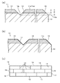
本実施形態では、本実施形態に係る木質板状建材の製造方法により製造した木質板状建材として、図4(c)に示すように、床材10を例示している。
床材10は、平面視して長方形状とされており、例えば、1尺(303mm)×6尺(1818mm)程度の長尺板状体とされている。
この床材10は、図4(b)に示すように、木質基材12と、その表面側のスライス単板13とを積層一体化した構造とされている。
このスライス単板13は、後記するように、高圧高温水蒸気による加熱処理が施された木材を湿潤状態のままでスライスして作製されたものである。
Embodiments of the present invention will be described below with reference to the drawings.
In this embodiment, as shown in FIG.4 (c), the
The
As shown in FIG. 4 (b), the
As will be described later, this
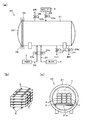
まず、本実施形態に係る木質板状建材の製造方法に用いられる加熱処理装置の概略構成について図2に基づいて説明する。
加熱処理装置としての高圧高温水蒸気釜(以下、蒸気釜と略す。)20は、図2(a)に示すように、横長円筒形状の容器本体21の開口を開閉蓋22で閉止して構成され、この開閉蓋22は、フェルール継手やクランプ継手、ボルトナット機構等の緊締手段29により、容器本体21を気密的に封止し、かつ容器本体21に対して着脱自在または開閉自在とされている。尚、図2(c)では、開閉蓋22を取り外した状態を示している。
これら容器本体21及び開閉蓋22は、加熱処理する木材としてのフリッチ材1(図2(c)参照)への金属汚染を防止する観点からステンレス等の汚染性が少なく、かつ耐圧性のある金属材料で製されたものとしてもよい。
この容器本体21の内部には、図2(c)に示すように、容器本体21の両側部に回転自在に支持されたローラー部材21aが、開口部側から奥側に向けて複数本、設けられている。このローラー部材21aには、被処理物が載置される載置プレート8が配置され、フリッチ材1の出し入れが容易に可能となっている。
First, the schematic structure of the heat processing apparatus used for the manufacturing method of the wooden board building material which concerns on this embodiment is demonstrated based on FIG.
A high-pressure and high-temperature steam kettle (hereinafter referred to as a steam kettle) 20 as a heat treatment apparatus is configured by closing the opening of a horizontally long
The container
As shown in FIG. 2 (c), a plurality of
容器本体21の下部には、高圧高温水蒸気供給源3からの高圧高温水蒸気を蒸気釜20内に供給する水蒸気供給管23と、加圧水供給源4からの加圧水を蒸気釜20内に供給する加圧水供給管24と、液化した水蒸気等を蒸気釜20内から排出するドレン管27と、排水管28とが接続されている。
また、容器本体21の上部には、加圧エアー供給源5からの加圧エアーを蒸気釜20内に供給する加圧エアー管25と、蒸気釜20内からの蒸気乃至はガスを排出する排気管26とが接続されている。
A
Further, a
高圧高温水蒸気供給源3としては、高圧ボイラーなどを採用するようにしてもよい。
加圧水供給源4としては、高圧水タンクや高圧ポンプなどを採用するようにしてもよい。
加圧エアー供給源5としては、エアーコンプレッサーなどを採用するようにしてもよい。
上記した各配管23,24,25,26,27,28には、それぞれの管路途中に、開閉バルブ23a,24a,25a,26a,27a,28aが設けられている。
また、ドレン管27には、管路途中の適所に、フィルタやスチームトラップ等が設けられている。
尚、高圧高温水蒸気釜20の具体的構成は、図示したものに限られず、高圧高温水蒸気による木材の加熱処理が可能な構成であれば、どのようなものでもよい。
As the high pressure / high temperature
As the pressurized
An air compressor or the like may be employed as the pressurized
The above-described
Further, the
The specific configuration of the high-pressure and high-
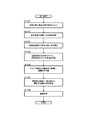
次に、本実施形態に係る木質板状建材の製造方法の一例について、図1〜図4に基づいて説明する。
<木材配置工程(ステップ100)>
まず、図2(b)に示すように、加熱処理対象としての複数(図例では、12本)のフリッチ材1,1・・・を、横方向に並べるとともに、高さ方向(厚さ方向)に桟部材6を介在させて積層したものを、図2(c)に示すように、桟部材6を介在させて載置プレート8に載置し、蒸気釜20内に配置する。
また、後記する冷却工程において加圧水を供給して水没させる際に、蒸気釜20内に配置した各フリッチ材1が浮き上がらないよう、適宜の浮き上がり防止手段7を配置する。
Next, an example of the manufacturing method of the wood board building material which concerns on this embodiment is demonstrated based on FIGS.
<Wood placement process (step 100)>
First, as shown in FIG. 2 (b), a plurality of (12 in the example) flitch materials 1, 1... As a heat treatment target are arranged in the horizontal direction and the height direction (thickness direction). 2) are stacked on the mounting plate 8 with the
In addition, when the pressurized water is supplied and submerged in the cooling step described later, appropriate lifting prevention means 7 is disposed so that each flitch material 1 disposed in the
この浮き上がり防止手段7としては、図例では、蒸気釜20内に配置されたフリッチ材1に見合った重し7としているが、適宜重量とされた金属製の網籠等により、浮き上がり防止手段7を構成するようにしてもよい。または、最上段のフリッチ材1(または、その上方に配された桟部材6)と、載置プレート8とを、金属製のワイヤーロープなどを巻回して固定保持するなど、フリッチ材1の浮き上がりを防止し得るものであればどのようなものでもよい。
In the illustrated example, the lifting prevention means 7 is a weight 7 corresponding to the flitch material 1 disposed in the
桟部材6としては、蒸気釜20と同様の金属材料から製されたもの、または、木質系材料からなるものとしてもよい。このような桟部材6は、加熱処理対象としての木材(本例では、フリッチ材1)のサイズに応じて、設けないようにしてもよいが、木材間に介在させることで、高圧高温水蒸気との接触表面積が拡大し、高圧高温水蒸気を木材内部に比較的、迅速に浸透させることができ、効率的な加熱処理を実行することができる。
また、本実施形態では、桟部材6を、蒸気釜20内に配置されたフリッチ材1が蒸気釜20の内壁(図例では、載置プレート8)に接触しないよう、最下段のフリッチ材1と、載置プレート8との間にも介在させるようにしている。また、浮き上がり防止手段7を図例のように、重し7とした場合には、この重し7と、最上段のフリッチ材1とが接触しないよう、これらの間にも桟部材6を介在させるようにしてもよい。
The
In the present embodiment, the
この加熱処理対象としての木材(本例では、フリッチ材1)は、乾燥処理をしていない、生材や煮沸または蒸煮木材等の相当の水分を含んだものとすることが高圧高温水蒸気の内部への浸透性の観点から好ましく、その含水率が、30%(ドライベース)以上程度の生材としてもよい。
また、その原料樹種としては、ブナやナラ、スギ、マカバ、ビーチ、オーク、チーク、ハードメープル、チェリー、ウォールナット、ホワイトアッシュ、マホガニー、その他の種々の樹種が挙げられる。ブナ材等の散孔材は、ナラ材等の環孔材に比べて、木目を強調することが困難な樹種であるが、このような散孔材にも、高圧高温水蒸気による加熱処理を施すことで、熱着色され、木目を強調することができる。
The wood as the heat treatment target (in this example, the flitch material 1) contains a considerable amount of moisture such as raw materials, boiled or steamed wood, etc. that has not been subjected to a drying treatment. It is preferable from the viewpoint of permeability to water, and it may be a raw material having a moisture content of about 30% (dry base) or more.
In addition, examples of the tree species include beech, oak, cedar, merkaba, beach, oak, teak, hard maple, cherry, walnut, white ash, mahogany, and other various tree species. Diffuse material such as beech wood is a tree species that is more difficult to emphasize the grain than ring material such as oak wood. In this way, it is colored by heat and can emphasize the grain.
本実施形態では、加熱処理対象としての木材を、角柱状に加工されたフリッチ材1とし、また、本実施形態では、縦(厚さ)、横、及び長さのうちの少なくともいずれか一つが、180mm以下のものとしており、図例では、厚さ47mm、幅114mm及び長さ480mmのものを示している。このように、木材を、縦(厚さ)、横、及び長さのうちの少なくともいずれか一つを、180mm以下のものとすることで、後記する加熱処理工程及び冷却工程において、木材の表面と心部との温度上昇差(温度下降差)を効率的に低減でき、木材の表面割れや強度劣化等を効率的に低減できるとともに、効率的な加熱処理及び冷却を実行することができる。 In the present embodiment, the wood as the heat treatment target is the flitch material 1 processed into a prismatic shape, and in the present embodiment, at least one of length (thickness), width, and length is 180 mm or less, and in the illustrated example, the thickness is 47 mm, the width is 114 mm, and the length is 480 mm. In this way, the surface of the wood in the heat treatment step and the cooling step to be described later is achieved by making the wood at least one of vertical (thickness), horizontal, and length 180 mm or less. The temperature increase difference (temperature decrease difference) between the center portion and the core portion can be efficiently reduced, and surface cracks and strength deterioration of the wood can be efficiently reduced, and efficient heat treatment and cooling can be performed.
<加熱処理工程(ステップ101)>
上記のように、蒸気釜20内に、フリッチ材1を配置した後、開閉蓋22により蒸気釜20を密閉し、上記した各バルブのうち、水蒸気供給バルブ23a、排気バルブ26a及びドレンバルブ27aを開とし、その他のバルブ24a,25a,28aを閉とし、蒸気釜20内に、高圧高温水蒸気を供給して、蒸気釜20内の空気を水蒸気に置換する。
次いで、上記状態から排気バルブ26aを閉とし、高圧高温水蒸気を供給して、例えば、1℃/分〜3℃/分程度で徐々に蒸気釜20内を、所定の処理温度となるまで昇温させる。
この加熱処理条件としての処理温度(蒸気釜20内の雰囲気温度)は、105℃以上、160℃以下(圧力範囲で、0.2kgf/cm2G(約0.02MPaG)以上、5.3kgf/cm2G(約0.52MPaG)以下)程度、好ましくは、150℃(3.9kgf/cm2G(約0.37MPaG))以下程度としてもよい。
尚、この処理温度は、例えば、蒸気釜20の内壁に設置した適宜の温度センサー等により計測して制御するようにしてもよく、或いは、圧力計等により蒸気釜20内の圧力を計測して制御するようにしてもよい。
<Heat treatment process (step 101)>
As described above, after the flitch material 1 is disposed in the
Next, the
The treatment temperature (atmosphere temperature in the steam kettle 20) as the heat treatment conditions is 105 ° C. or more and 160 ° C. or less (in the pressure range, 0.2 kgf / cm 2 G (about 0.02 MPaG) or more and 5.3 kgf / cm 2 G (about 0.52 MPaG) or less, preferably about 150 ° C. (3.9 kgf / cm 2 G (about 0.37 MPaG)) or less.
The processing temperature may be measured and controlled by, for example, an appropriate temperature sensor installed on the inner wall of the
上記処理温度が、上記下限温度未満であれば、木材組成成分のヘミセルロースが十分に熱分解されず、木材の均質化並びに木材への熱着色及び耐光性の付与が十分になされない傾向がある一方、上記上限温度を超えれば、加熱処理対象としての木材のサイズや処理時間によっては、ヘミセルロースの熱分解が過剰となり木材繊維細胞組織が劣化する傾向があり、木材の強度が低下する傾向がある。尚、木材のサイズを小さくし、処理時間を短くすれば、160℃を超えて、190℃以下程度の処理温度でも、木材の強度がそれほど劣化することなく、木材の均質化並びに木材への熱着色及び耐光性の付与がある程度は可能である。
この処理温度は、加熱処理対象としての木材(本例では、フリッチ材1)の着色度合いに大きく寄与し、この処理温度を上記範囲内で適宜、設定することで、木材の着色度を容易にコントロールすることができる。
If the treatment temperature is less than the above lower limit temperature, the hemicellulose of the wood composition component is not sufficiently pyrolyzed, and there is a tendency that the homogenization of the wood and thermal coloring and light resistance imparting to the wood are not sufficiently achieved. If the upper limit temperature is exceeded, depending on the size of the wood as the heat treatment target and the treatment time, the thermal decomposition of hemicellulose tends to be excessive and the wood fiber cell tissue tends to deteriorate, and the strength of the wood tends to decrease. If the size of the wood is reduced and the treatment time is shortened, the strength of the wood will not deteriorate so much even at a treatment temperature exceeding 160 ° C. and below 190 ° C. Coloring and light resistance can be imparted to some extent.
This treatment temperature greatly contributes to the degree of coloration of the wood as a heat treatment target (in this example, the flitch material 1), and by appropriately setting this treatment temperature within the above range, the degree of coloration of the wood can be easily achieved. Can be controlled.
また、この蒸気釜20内における高圧高温水蒸気による加熱処理は、加熱処理対象としての木材(本例では、フリッチ材1)の表面温度(実質的には釜内の雰囲気温度)と、木材心部の温度との温度差が、10℃以内となるように加熱処理条件としての処理時間を設定するようにしてもよい。好ましくは、上記温度差が10℃以内となった後、10分以上程度の保持時間を設けるようにしてもよい。より好ましくは、木材心部の温度が、上記処理温度と同程度(105℃以上、160℃以下、好ましくは150℃以下)となるまで、または、同程度となった後に10分以上程度の保持時間を設けるようにしてもよい。
In addition, the heat treatment with the high-pressure and high-temperature steam in the
このような処理時間とすることで、木材内部における色ムラを低減できるとともに、木材の均質化をより向上させることができ、歩留まり、生産性を向上させることができる。
上記所定の処理温度に達した後の処理時間は、木材の樹種や、サイズ、釜内温度等にもよるが、上記程度のフリッチ材1のサイズで、ブナやナラ材等の場合には、1時間〜4時間程度としてもよい。
尚、上記処理温度を設定する態様に代えて、この処理時間を適宜、設定することで、木材の着色度をコントロールするようにしてもよい。
By setting it as such processing time, the color nonuniformity inside a timber can be reduced, the homogenization of a timber can be improved more, and a yield and productivity can be improved.
The processing time after reaching the predetermined processing temperature depends on the wood species, size, temperature in the pot, etc., but in the case of beech, oak, etc. It is good also as about 1 hour-4 hours.
In addition, it may replace with the aspect which sets the said processing temperature, and you may make it control the coloring degree of wood by setting this processing time suitably.
<木材冷却、釜内降圧工程(ステップ102)>
上記のように加熱処理工程を実行した後、木材の冷却、及び蒸気釜20内を降圧する。
この蒸気釜20の降圧処理は、木材の心部が所定温度以下となるまで冷却された後に、実行することが木材の乾燥割れ等を防ぐ観点から好ましい。
この所定温度は、100℃以下程度、好ましくは、90℃以下程度としてもよい。
本実施形態では、冷却工程の効率化及び木材の乾燥割れをより効率的に防止するために、降圧処理を実行する前に、蒸気釜20内を所定の高圧状態に維持した状態で木材を水没させて冷却するようにしている。
<Wood cooling, pressure reduction process in the pot (step 102)>
After performing the heat treatment process as described above, the wood is cooled and the pressure in the
It is preferable from the viewpoint of preventing dry cracking of the wood, etc., that the pressure reduction processing of the
This predetermined temperature may be about 100 ° C. or lower, preferably about 90 ° C. or lower.
In the present embodiment, in order to improve the efficiency of the cooling process and prevent dry cracking of the wood more efficiently, the wood is submerged in a state where the inside of the
すなわち、本実施形態では、上記加熱処理工程を実行した後、水蒸気供給バルブ23aを閉とし、加圧水供給バルブ24a及び加圧エアー供給バルブ25aを開として、蒸気釜20内の圧力が低下しないように高圧状態を保ちながら、蒸気釜20内のフリッチ材1を水没させて冷却する。好ましくは、この冷却の際、蒸気釜20内の圧力が上記加熱処理時における圧力以上となるように高圧状態を保ちながら実行するようにしてもよい。或いは、加熱処理時における圧力にもよるが、急激な圧力変動が生じて加熱処理後の木材の表面に乾燥割れ等が生じない程度に、加熱処理時における圧力を少し下回った程度の高圧状態を保ちながら、水没させて冷却するようにしてもよい。
That is, in this embodiment, after the heat treatment step is performed, the water
この冷却工程実行時における蒸気釜20内の所定の高圧状態は、加圧水供給バルブ24a及び加圧エアー供給バルブ25aを開として、加圧水、加圧エアーを供給しながら、圧力計等の計測値に基づいて、排気バルブ26aを開閉制御乃至は開度制御することで調整するようにしてもよい。
また、上記加圧水の供給は、蒸気釜20内における圧力変動や蒸気釜20自体の劣化(金属疲労)を抑えるために、蒸気釜20内に供給された加圧水が蒸気釜20内において飛散等しないよう、蒸気釜20内の下方から徐々に、かつ穏やかに供給することが好ましい。
さらに、冷却効率を向上させるために、この冷却工程を実行する際には、加圧水供給バルブ24a及び排水バルブ28aを開閉制御乃至は開度制御することで、蒸気釜20内の冷却用水の入れ替えを行うようにしてもよい。
The predetermined high pressure state in the
Further, the pressurized water is supplied so that the pressurized water supplied in the
Further, in order to improve the cooling efficiency, when performing this cooling step, the pressurized
尚、上記冷却工程において、蒸気釜20内に直接、冷却用水(加圧水)を供給する態様に代えて、蒸気釜20内に、フリッチ材1を収容可能で、かつ貯水可能な容器を設置し、この容器内に加圧水を供給するようにしてもよい。この場合は、この容器の下部に水蒸気供給管23、加圧水供給管24、ドレン管27及び排水管28を接続するようにすればよい。また、この場合、ドレン管27及び排水管28をさらに蒸気釜20の下部に接続するようにしてもよい。この容器は、蒸気釜20に対して出し入れ自在とされたものとしてもよい。
このように、フリッチ材1を冷却するための加圧水が供給される容器を蒸気釜20内に設置することで、蒸気釜20の劣化を効率的に低減できる。また、この場合は、容器を上記したような汚染性の少ないステンレス製等とし、蒸気釜を耐圧性のある鉄製等としてもよい。これによれば、より効率的に蒸気釜20の劣化を低減できる。
また、上記冷却工程実行時に蒸気釜20内に導入する加圧エアーは、木材の酸化抑制の観点から窒素ガスを使用するようにしてもよい。
In the cooling step, instead of supplying the cooling water (pressurized water) directly into the
In this way, by installing the container to which the pressurized water for cooling the flitch material 1 is supplied in the
Moreover, you may make it use the nitrogen gas from a viewpoint of the oxidation suppression of wood for the pressurized air introduce | transduced in the
さらに、上述のように冷却用水を供給して強制的に加熱処理後の木材(処理木材)を冷却する態様に代えて、上記加熱処理工程の後、水蒸気供給バルブ23aを閉とし、木材の心部が上記所定温度以下となるまで自然冷却するようにしてもよい。または、水蒸気供給バルブ23aを閉とし、蒸気釜20内を所定の高圧状態に維持した状態で、加圧エアー供給バルブ25a及び排気バルブ26aを開閉制御乃至は開度制御することで、蒸気釜20内のガスの入れ替えを行い、冷却するような態様としてもよい。
Further, instead of supplying the cooling water and forcibly cooling the heat-treated wood (treated wood) as described above, after the heat treatment step, the water
上記冷却工程を実行した後、加圧水供給バルブ24a及び加圧エアー供給バルブ25aを閉とし、排気バルブ26a及び排水バルブ28aを開として、蒸気釜20内の圧力を大気圧に復帰させ、蒸気釜20内の冷却用水を蒸気釜20外に排出する(釜内降圧工程)。
この蒸気釜20内の圧力を大気圧に復帰させる際にも、急激な圧力変動が生じないよう、徐々に大気圧に復帰させるようにしてもよい。
尚、蒸気釜20内の降圧は、蒸気釜20内の冷却用水を蒸気釜20外に排出する前に、排気バルブ26aを開にして行うようにしてもよく、または、排気バルブ26a及び排水バルブ28aの両方を開として冷却用水を排出しながら行うようにしてもよく、さらには、冷却用水を排出した後(実質的には、冷却用水の排出により蒸気釜20内はある程度、降圧する)に、排気バルブ26aを開にして行うようにしてもよい。
After performing the cooling step, the pressurized
When returning the pressure in the
The pressure reduction in the
<処理木材精寸、集成工程>
上記釜内降圧工程を実行した後、処理木材としてのフリッチ材1を蒸気釜20から取り出し、精寸仕上げを行う。例えば、上記所定のサイズとされた各フリッチ材1を、厚さ45mm、幅101mm及び長さ455mmとなるように精寸する。この際、長手方向両端面はクロスカットソー加工により精寸処理し、その他の面は、モルダー加工により精寸処理するようにしてもよい。
このようなフリッチ材1の全面の精寸処理により、上記加熱処理工程において、木材の組成成分であるリグニンに含まれるフェノール類似の低分子樹脂が変質し、副生成されてフリッチ材1の表面に析出した耐光性の低い酸化着色物が除去されるとともに、フリッチ材1の全面が平滑となる。
<Exact processing wood, assembly process>
After performing the above-mentioned pressure reduction process in the pot, the flitch material 1 as the treated wood is taken out from the
Due to the precise processing of the entire surface of the flitch material 1, the low-molecular resin similar to phenol contained in the lignin, which is a composition component of wood, is altered in the heat treatment step, and is generated as a by-product on the surface of the flitch material 1. The deposited oxidation coloring matter having low light resistance is removed, and the entire surface of the flitch material 1 becomes smooth.
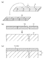
上記のように各フリッチ材1を精寸処理した後、図3(a)に示すように、フリッチ材1の厚さ面を隣接するフリッチ材1に対面させるようにして集成接着し、フリッチ集成体2を作製する。
本実施形態では、長手方向にそれぞれ4つのフリッチ材1を接合し、短手方向が三列となるように集成接着しており、さらに、長手方向には、集成接着されたフリッチ材1が千鳥状にずれて配置されるように、適宜長さに切断したフリッチ材1を振り分けて集成接着するようにしている。
上記集成接着に使用される接着剤としては、湿潤状態のフリッチ材1の接着が可能な接着剤とすればよく、例えば、湿気硬化型ウレタン接着剤等を採用するようにしてもよい。
After each flitch material 1 has been subjected to precise processing as described above, as shown in FIG. The body 2 is produced.
In the present embodiment, four flitch materials 1 are joined in the longitudinal direction, and are bonded together so that the lateral direction is in three rows. The flitch material 1 cut to an appropriate length is distributed and assembled and adhered so as to be displaced in a shape.
As an adhesive used for the above-mentioned laminated adhesion, an adhesive capable of adhering the wet-state flitch material 1 may be used. For example, a moisture-curing urethane adhesive or the like may be adopted.
<スライス加工工程(ステップ103)>
上記のように作製されたフリッチ集成体2を、湿潤状態のままで横突きスライサー機に導入し、所定厚さとなるようスライス加工して、図3(a)に示すように、スライス単板13を作製する。
ここに、湿潤状態とは、上記加熱処理工程の後のスライス加工対象としてのフリッチ集成体2の含水率が所定程度以上の状態を指しており、このフリッチ集成体2の含水率は、30%以上程度とすることがスライス加工性の観点から好ましい。
<Slicing process (step 103)>
The flitch assembly 2 produced as described above is introduced into a laterally slicing machine in a wet state, sliced to a predetermined thickness, and as shown in FIG. Is made.
Here, the wet state refers to a state in which the moisture content of the flitch assembly 2 as a slice processing target after the heat treatment step is not less than a predetermined level, and the moisture content of the flitch assembly 2 is 30%. It is preferable from the viewpoint of slicing workability to be about the above.
上記のように高圧高温水蒸気による加熱処理を施した木材(本例では、フリッチ集成体2)は、均質化されているので、その木材を湿潤状態のままでスライスしてスライス単板13を作製することで、スライス加工性が向上し、従来のようなスライス加工時に生じる逆目割れが生じ難く、効率的に肉厚のスライス単板を作製することができる。
また、本実施形態のように、加熱処理対象としての木材をフリッチ材1とし、このフリッチ材1を集成接着したフリッチ集成体2をスライス加工してスライス単板13を作製する態様とすることで、比較的、肉厚のものでもスライス加工性が向上するので、フリッチ材1を集成接着したフリッチ集成体2をスライス加工して複数のフリッチ材1からなる集成されたスライス単板13を容易に作製できる。従って、後の積層工程において、複数枚の単板を個々に木質基材に並べるようにして貼着する必要がなく、製造工程の簡略化を図ることができる。
さらに、例えば、上記した加熱処理工程時における、各フリッチ材1の加熱処理条件(上記処理温度や上記処理時間など)を適宜、設定し、各フリッチ材1の着色度合いを調整することで、色調の異なるフリッチ材1を作製することができる。この色調の異なるフリッチ材1を、趣向等に応じて組み合わせて集成接着し、スライスすることで、種々の柄パターン(乱貼り状、パーケット状、市松状等)のスライス単板13を作製することもできる。
The wood that has been heat-treated with high-pressure and high-temperature steam as described above (in this example, the flitch assembly 2) is homogenized, so that the wood is sliced in a wet state to produce a
Further, as in this embodiment, the wood as the heat treatment target is the flitch material 1 and the sliced
Furthermore, for example, by appropriately setting the heat treatment conditions (the treatment temperature, the treatment time, etc.) of each flitch material 1 during the heat treatment step described above, and adjusting the coloring degree of each flitch material 1, Different flitch materials 1 can be produced. The flitch materials 1 having different color tones are combined, bonded and sliced according to the taste and the like, and sliced to produce sliced
上記所定厚さは、スライス加工性、コスト性、木質板状建材の意匠性及び外観劣化の低減等の観点から、0.35mm以上、2.25mm以下程度、好ましくは、0.40mm以上、2.00mm以下程度としてもよい。
上記所定厚さが、上記下限厚さ未満であれば、耐摩耗性が低くなる傾向があるとともに、後記するように、所定深さの溝部や面取り部の形成が困難となる傾向があり、意匠性が低下する傾向がある。一方、上記上限厚さを超えれば、高コストになる傾向があるとともに、スライス加工性が悪化する傾向があり、スライス単板の裏面に割れが発生する傾向がある。
上記のような所定厚さのスライス単板13とすることで、0.15mm〜0.25mm程度の厚さとされた一般的な突板と比べて、磨耗等による木質基材の露出をより効果的かつ効率的に低減できる十分な厚さとなり、外観の劣化をより効率的に防止できる。
The above-mentioned predetermined thickness is 0.35 mm or more and 2.25 mm or less, preferably 0.40 mm or more, 2 from the viewpoint of slicing workability, cost performance, design properties of woody plate-shaped building materials and reduction of appearance deterioration, and the like. It may be about 0.000 mm or less.
If the predetermined thickness is less than the lower limit thickness, the wear resistance tends to be low, and as described later, the formation of grooves and chamfered portions having a predetermined depth tends to be difficult. Tend to decrease. On the other hand, if the thickness exceeds the upper limit, the cost tends to be high and the slice workability tends to be deteriorated, and the back surface of the slice single plate tends to crack.
By using the sliced
尚、本実施形態では、加熱処理対象としての木材をフリッチ材1とし、このフリッチ材1を上記のように集成接着したフリッチ集成体2をスライス加工してスライス単板13を作製する態様について示しているが、このような態様に限られない。例えば、加熱処理対象を、所望する木質板状建材の大きさに合わせた形状の肉厚の板材とし、この板材に対して上記各工程を必要に応じて実行した後、この板材をスライス加工してスライス単板を作製するようにしてもよい。換言すれば、フリッチ材の一つを、所望する木質板状建材の大きさに応じた形状とし、上記各工程を必要に応じて実行した後、集成等することなく、このフリッチ材からスライス単板を作製するようにしてもよい。
In the present embodiment, the wood as the heat treatment target is the flitch material 1, and the sliced
<積層工程(ステップ104)>
上記のように作製されたスライス単板13を、図3(b)及び図3(c)に示すように、木質基材12に貼着して積層体11を作製する。
この積層接着に使用される接着剤としては、各種水性接着剤やエマルション接着剤等としてもよく、例えば、ゴムラテックス系エマルション接着剤としてもよい。
また、接着剤を介して木質基材12とスライス単板13とを積層した後、熱プレス機(ホットプレス機)に導入し、加熱圧締して乾燥硬化させるようにしてもよい。
尚、木質基材12とスライス単板13との間に、熱プレス時における接着剤やスライス単板等からの水蒸気の放出を促すために、紙材等を介在させて積層接着するようにしてもよい。
また、接着剤の種類に応じて、加熱圧締する態様に代えて、コールドプレスとしてもよく、自然乾燥としてもよい。
<Lamination process (step 104)>
As shown in FIGS. 3 (b) and 3 (c), the sliced
As the adhesive used for the lamination adhesion, various water-based adhesives, emulsion adhesives, and the like may be used. For example, rubber latex emulsion adhesives may be used.
Moreover, after laminating the
The
In addition, depending on the type of adhesive, instead of the heat-clamping mode, a cold press or natural drying may be used.
上記した木質基材12としては、合板やLVL(単板積層材)等の木質積層板、パーティクルボード等の木質ボード、またはインシュレーションボードやMDF(中密度繊維板)等の木質繊維板などの木質系材料を板状に加工したものが挙げられる。または、合成樹脂系材料に、木粉や無機フィラー、相溶化剤、着色剤などを所定の含有割合で含有させた木粉・プラスチック複合材(WPC)を板状に加工したものとしてもよい。これらは、適宜、組み合わせて積層し、木質基材12を構成するようにしてもよい。例えば、合板やパーティクルボード等の表面に、比較的、表面硬度の高いMDFやWPC等を積層して木質基材12を構成するようにしてもよい。
As the above-mentioned
<表面加工工程(ステップ105)>
上記のように積層体11を作製した後、図4(a)に示すように、当該積層体11の表面11aに、溝部14及び面取り部15を形成する。
本実施形態では、図4(c)に示すように、縦横に複数本の溝部14を形成し、四周の全周に亘って面取り部15を形成している。
<Surface processing step (step 105)>
After producing the
In this embodiment, as shown in FIG.4 (c), the
溝部14は、図4(a)に示すように、スライス単板13の表面13aから、溝部14の下端である底部14aまでの深さDが、スライス単板13の厚さTの二倍以内となるように形成されている。
また、この溝部14は、図例では、木質基材12の層内に底部14aが達するように切削加工されるとともに、その断面形状(溝部自体の長手方向に直交する方向の縦断面形状)がV字形状とされている。
また、本実施形態では、複数本の溝部14を、上記のように集成接着された各フリッチ材1の接合部(継ぎ目)に沿って形成するようにしている(図3(a)及び図4(c)参照)。
As shown in FIG. 4A, the
In the illustrated example, the
Further, in the present embodiment, a plurality of
上記のように、各フリッチ材1の継ぎ目に沿って、上記寸法の溝部14を形成することで、スライス単板13が肉厚であることと相俟って、この溝部14において無垢材を突き合わせて集成した無垢集成材のような外観となり、製造後の木質板状建材10の表面の見栄えをより向上させることができる。
特に、各フリッチ材1の着色度合いを異ならせたものを集成してスライス単板13を作製し、その継ぎ目に沿って上記寸法の溝部14を形成することで、溝部14の両側面に露出した各フリッチ材1の色調が異なるものとなるので、より無垢集成材に近い外観を呈するものとできる。
つまり、溝部において基材が大きく露出した従来のものでは、表面層のスライス単板が、溝部で分断されたような外観となり、無垢感を呈することが困難であるが、本実施形態のように、スライス単板13を肉厚のものとし、上記寸法の溝部14を形成することで、無垢材に溝部を形成したような外観とすることができ、見栄えを向上させることができる。
これら溝部14の形成箇所や本数は、意匠性等の観点から適宜、選択可能であり、図例のように、縦横の全ての継ぎ目に沿って溝部を形成する態様に代えて、例えば、長手方向に沿う継ぎ目のみに溝部を形成するようにしてもよい。
As described above, along with the seam of each flitch material 1, the
In particular, the sliced
That is, in the conventional one in which the base material is greatly exposed in the groove portion, the sliced single plate of the surface layer has an appearance as if it was divided by the groove portion, and it is difficult to exhibit a solid feeling, but as in this embodiment By forming the
The location and number of the
面取り部15は、溝部14と同様、スライス単板13の表面13aから、面取り部15の下端である下端縁部15aまでの深さDが、スライス単板13の厚さTの二倍以内となるように形成されている。
この面取り部15は、図例では、積層体11の表面端縁部を斜めに切除したC面取り形状とされており、その下端縁部15aが木質基材12の端面に位置するように、すなわち、面取り部15の形成された部位に、木質基材12が露出するように形成されている。
また、この面取り部15は、上記した溝部14の断面形状に合わせた形状とされている。つまり、本実施形態では、隣接する木質板状建材(図例では、床材1)同士が接合された際に、各木質板状建材に形成された面取り部によって、これら木質板状建材の端部間に、溝部14と略同寸同形状の目地溝が形成されるように面取り部を形成している。
In the chamfered
In the illustrated example, the chamfered
The chamfered
これら溝部14及び面取り部15の深さDは、スライス単板13の厚さTの二倍以内となるように形成するようにすればよいが、本実施形態のように、木質板状建材を床材10とした場合や内装の壁材とした場合には、意匠性の観点や手触り感等の観点から、その深さを、0.6mm〜3.0mm程度とすることが好ましい。この深さが、下限深さ未満であれば、溝部や面取り部としての立体感が失われ、加工性の観点からも困難となる傾向がる。一方、上限深さを超えれば、溝部や面取り部が目立ち過ぎる傾向があり、特に、床材とした場合には、塵埃等の堆積や歩行時の違和感等が生じる傾向がある。
このような深さとし、上述のように、スライス単板13を上記所定厚さとすることで、このような溝部14や面取り部15が形成された木質板状建材の表面の意匠性を、より効率的に向上させることができる。
What is necessary is just to make it form so that the depth D of these
With such a depth, as described above, the sliced
尚、溝部14の幅(及び面取り部15により形成される上記目地溝の幅)は、深さの二倍以内程度とすることが好ましい。例えば、図例のように、断面V字形状で溝底の角度が90度とされた溝部14の深さDが1.6mmとすれば、3.2mm程度の幅としてもよい。また、上記のように、溝部14を、その底部14aが木質基材12の層内に達するように形成し、かつ、木質基材12が露出するように面取り部15を形成した場合には、これら溝部14及び面取り部15の形成された部位において、スライス単板13の露出面積が、木質基材12の露出面積を上回るように、これら溝部14及び面取り部15を形成することが好ましい。
また、溝底の角度は、上記のような90度とされたものに限られず、70度〜120度程度としてもよく、これに応じた面取り部の形状としてもよい。
The width of the groove portion 14 (and the width of the joint groove formed by the chamfered portion 15) is preferably within about twice the depth. For example, as shown in the figure, if the depth D of the
Further, the angle of the groove bottom is not limited to 90 degrees as described above, but may be about 70 degrees to 120 degrees, or the shape of the chamfered portion corresponding to this.
さらに、図例では、溝部14及び面取り部15により形成される上記目地溝の断面形状を、V字形状としているが、U字形状、半円形状、上方に開口した倒コ字形状、逆台形状等、種々の形状としてもよい。
さらにまた、図例では、溝部14と上記目地溝との断面形状を、略同寸同形状としたものを例示しているが、これらが互いに異なる断面形状とされたものとしてもよい。
また、図例では、溝部14及び面取り部15を、これらの形成された部位において木質基材12が露出するように形成した態様を示しているが、上述のように、本実施形態によれば、スライス単板13を比較的、肉厚のものとできるので、これら溝部14及び面取り部15の下端14a,15aが、スライス単板13の厚み内に止まるように形成するようにしてもよい。これによれば、これらの部位において木質基材12が露出することなく、木質板状建材の意匠性をより向上させることができる。
Furthermore, although the cross-sectional shape of the joint groove formed by the
Furthermore, in the illustrated example, the cross-sectional shapes of the
Further, in the illustrated example, the
また、本実施形態では、上記のように溝部14及び面取り部15を形成する際、または、その前後の工程において、積層体11の四周端部に、図4(c)に示すように、隣接する木質板状建材(図例では、床材10)と実接合される雄実部17及び雌実部18を形成するようにしている。
このような実部17,18は、隣接する木質板状建材同士を接合する接合部を構成し、図例では、雄実部17と雌実部18とを備えた本実接合構造としているが、雇い実接合や相じゃくり接合構造等の他の接合構造とされたものとしてもよく、このような実接合部を設けないようにしてもよい。
Moreover, in this embodiment, when forming the
Such
尚、上記した溝部14及び面取り部15並びに実部17,18の加工は、トリマやルータ、テノーナー、カットソー等の適宜の木材加工工具、木材切削工具により形成するようにしてもよい。
また、上記した溝部14及び面取り部15並びに実部17,18を形成する前に、積層体11の表面11aを、ワイドベルトサンダーにて表面仕上げ処理(表面研磨処理)するようにしてもよい。この際、使用する番手は、スライス単板13に用いる樹種にもよるが、180番手〜320番手程度のものとし、積層体11の表面11aが平滑となるよう表面研磨するようにしてもよい。
In addition, you may make it form the process of the above-mentioned
Further, the
<塗装工程(ステップ106)>
上記のように表面加工処理が施された積層体11の表面(溝部14及び面取り部15を含む)11aに所定の塗装を施し、図4(b)に示すように、塗膜層16を形成する。
この塗装工程では、高圧高温水蒸気による加熱処理によって、スライス単板13には、熱着色が施されるとともに、耐光性が付与されているので、クリアー塗料のみを仕上げ塗装として施すようにしてもよい。このようなクリアー塗料のみによる仕上げ塗装によれば、塗装後の木質板状建材の表面の木質感が阻害されることがなく、意匠性を向上させることができる。
<Coating process (step 106)>
A predetermined coating is applied to the surface (including the
In this coating process, the
または、上記のように表面加工処理が施された積層体11の表面11aと、塗装後の表面との色差ΔEが、3.0以下程度となるように低濃度の塗料を塗布し、生地着色を施すようにしてもよい。
このように、積層体11の表面11aの地色と、塗装後の木質板状建材との色差ΔEが比較的小さくなるように生地着色を施すことで、塗装後の木質板状建材の表面の木質感が阻害されることがなく、意匠性を向上させることができる。また、表面に磨耗等が生じて塗膜の消失乃至はスライス単板13自体に磨耗が生じた場合にも、上記のように色差が小さく、スライス単板13の全体が熱着色されるとともに、耐光性が付与されているので、磨耗部位のスライス単板13の全体が消失しない限りは、磨耗前後、及びそれ以外の部位との違和感が生じることがなく、外観の劣化を防止できる。
さらに、比較的、高濃度の塗料により塗装する場合と比べて、溝部14や面取り部15と、それ以外の表面との不自然な色調の差異(濃淡)が生じ難く、より意匠性を向上させることができる。
Alternatively, a low-concentration paint is applied so that the color difference ΔE between the
Thus, by applying the fabric coloring so that the color difference ΔE between the ground color of the
Furthermore, as compared with the case of coating with a relatively high-concentration paint, an unnatural color difference (shading) between the
上記色差ΔEは、L*a*b*表色系またはハンターLab表色系によるものとしてもよい。
また、上記のように生地着色を施した後、上記同様のクリアー塗料を仕上げ塗装として施すようにしてもよい。
また、上記低濃度の塗料は、例えば、着色成分として各種色の顔料を主成分とした水性合成樹脂着色剤を希釈剤で希釈した水性合成樹脂塗料としてもよい。このような水性合成樹脂着色剤には、適宜、粘度調整剤や界面活性剤を添加するようにしてもよい。また、この希釈剤に対する顔料の配合比率は、上述のように、積層体11の表面11aとの色差ΔEが3.0以下程度となるように、低濃度の塗料とすればよく、例えば、15%以下程度のものとしてもよい。或いは、上記のようにクリアー塗料のみを仕上げ塗装とするようにしてもよい。
The color difference ΔE may be based on the L * a * b * color system or the Hunter Lab color system.
Further, after the fabric is colored as described above, a clear paint similar to the above may be applied as a finish coating.
The low-concentration paint may be, for example, an aqueous synthetic resin paint obtained by diluting an aqueous synthetic resin colorant mainly containing pigments of various colors as coloring components with a diluent. You may make it add a viscosity modifier and surfactant suitably to such an aqueous synthetic resin colorant. Further, the blending ratio of the pigment to the diluent may be a low-concentration paint so that the color difference ΔE with the
尚、上記各塗料の塗布方法としては、種々の塗布方法の採用が可能であるが、ロールコーター法を用いることで、例えば、スプレー塗布に比べて、飛散等による塗料の無駄や洗浄等の必要が生じず、生産性が向上される。また、同ロールコーター法を用いることで、例えば、カーテンフローコーター法に比べて、塗布量の微調整が可能であるため、濃淡等が形成され難く、塗装後の木質板状建材の意匠性をより効率的に向上させることができる。
また、上記した塗料の着色成分としての顔料または染料の割合は、塗装対象である積層体11の表面11aの地色や、塗装後の所望する色調等に応じて適宜、選択可能であり、木質感を阻害しないように、白色系の塗料を用いるようにしてもよいが、その他、半透明塗料や淡色系の塗料等としてもよい。
さらに、上記塗料としては、白色系やその他の水性ステインを、適宜、希釈したものとしてもよい。
Various coating methods can be used as the coating method for each paint. However, using the roll coater method, for example, compared to spray coating, waste of paint due to scattering or the like is necessary. Does not occur and productivity is improved. In addition, by using the roll coater method, for example, the coating amount can be finely adjusted compared to the curtain flow coater method, so that it is difficult to form shading and the like, and the design of the wooden plate-shaped building material after painting is improved. It can be improved more efficiently.
Further, the ratio of the pigment or dye as the coloring component of the paint described above can be appropriately selected according to the ground color of the
Furthermore, as the coating material, a white or other aqueous stain may be appropriately diluted.
上記のように各工程を経て、図4(c)に示すように、木質板状建材としての床材10が製造される。
以上のように、本実施形態に係る木質板状建材の製造方法によれば、木質板状建材10の表層側に積層されるスライス単板13を効率的に肉厚に加工できるとともに、意匠性の高い木質板状建材10を製造することができる。
Through the respective steps as described above, as shown in FIG. 4 (c), a
As mentioned above, according to the manufacturing method of the wooden plate-shaped building material which concerns on this embodiment, while being able to process the slice
尚、本実施形態に係る木質板状建材の製造方法により製造される木質板状建材としては、床材として施工されるものに限られず、相互に端部が接合されて互いの面取り部によって目地溝が形成される壁材や天井材などの他の内装材としてもよい。または、その他の内装パネル材や扉材、各種造作部材、家具材等を、本実施形態に係る木質板状建材の製造方法により製造するようにしてもよい。
また、本実施形態では、木質板状建材の表面端縁部の四周の全周に亘って面取り部を形成したものを例示しているが、少なくとも一辺の表面端縁部に面取り部を形成するようにしてもよい。
さらに、本実施形態では、木質板状建材の表面に、溝部及び面取り部を形成したものを例示しているが、これらのうちのいずれか一方のみを形成するようにしてもよい。
Note that the wood plate building material manufactured by the method for manufacturing a wood plate building material according to the present embodiment is not limited to one constructed as a flooring material, and the ends are joined to each other by the chamfered portions. It is good also as other interior materials, such as the wall material and ceiling material in which a gravel is formed. Or you may make it manufacture another interior panel material, door material, various artificial members, furniture materials, etc. with the manufacturing method of the wooden board-shaped building material which concerns on this embodiment.
Moreover, in this embodiment, although what chamfered part was formed over the perimeter of the four circumferences of the surface edge part of a wooden board building material is illustrated, a chamfer part is formed in the surface edge part of at least one side. You may do it.
Furthermore, in this embodiment, although the thing which formed the groove part and the chamfering part in the surface of the wooden board-shaped building material is illustrated, you may make it form only any one of these.
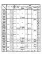
次に、本発明に係る製造方法により製造された木質板状建材の実施例の一例と比較例とを図5の表に基づいて説明する。
各実施例及び各比較例では、木質基材を、厚さが12mmの合板とし、また、含水率が40〜62%(ドライベース)程度の生材のナラ材を上記所定のサイズに形成した12本のフリッチ材を、処理対象としての木材とした。
Next, an example of a wood board building material manufactured by the manufacturing method according to the present invention and a comparative example will be described based on the table of FIG.
In each of the examples and comparative examples, the wood base material was a plywood having a thickness of 12 mm, and a raw oak material having a moisture content of about 40 to 62% (dry base) was formed in the predetermined size. Twelve flitch materials were used as the wood to be treated.
<フリッチ材処理条件>
実施例1〜19及び比較例8では、上記12本のフリッチ材を上記同様に桟部材を介在させて積層し、高圧高温水蒸気による上記加熱処理を施した。この加熱処理時における処理温度は、図5の表に示すように、実施例1〜6では、105℃、実施例7〜13では、135℃、実施例14〜19では、150℃、比較例8では、160℃とし、これら所定の処理温度に昇温させた後の処理時間を2時間とした。
また、高圧高温水蒸気による上記加熱処理を施した後、上記のように高圧状態を保ちながら水没させて冷却した。この冷却時間は、30分とし、フリッチ材温度が90℃以下となるまで冷却した後、蒸気釜内を降圧して、フリッチ材を取り出し、上記したように所定のサイズに精寸処理した。次いで、このフリッチ材を上記したように湿気硬化型ウレタン接着剤で集成接着し、フリッチ集成体を作製した。
<Flitch material processing conditions>
In Examples 1 to 19 and Comparative Example 8, the 12 flitch materials were laminated with a crosspiece interposed in the same manner as described above, and the heat treatment with high-pressure and high-temperature steam was performed. As shown in the table of FIG. 5, the heat treatment temperature is 105 ° C. in Examples 1 to 6, 135 ° C. in Examples 7 to 13, 150 ° C. in Examples 14 to 19, and Comparative Example. In No. 8, the temperature was set to 160 ° C., and the processing time after raising the temperature to the predetermined processing temperature was 2 hours.
Moreover, after performing the said heat processing by a high voltage | pressure high temperature steam, it submerged and cooled, maintaining a high voltage | pressure state as mentioned above. The cooling time was 30 minutes, and after cooling until the flitch material temperature was 90 ° C. or lower, the inside of the steam kettle was depressurized, the flitch material was taken out, and precisely processed to a predetermined size as described above. Next, the flitch material was assembled and bonded with a moisture-curing urethane adhesive as described above to produce a flitch assembly.
一方、比較例1〜3では、上記12本のフリッチ材を加熱処理等することなく、精寸処理して集成接着し、フリッチ集成体を作製した。
また、比較例4〜7では、上記12本のフリッチ材を、100℃で蒸煮処理し、精寸処理して集成接着し、フリッチ集成体を作製した。
On the other hand, in Comparative Examples 1 to 3, the above-mentioned 12 flitch materials were subjected to precise processing without being subjected to heat treatment or the like and assembled and bonded to produce a flitch assembly.
In Comparative Examples 4 to 7, the 12 flitch materials were steamed at 100 ° C., precisely processed and assembled and bonded to produce a flitch assembly.
<スライス加工条件>
上記のようにそれぞれ作製したフリッチ集成体を横突きスライサーによりスライス加工して所定厚さのスライス単板を作製した。
各実施例及び比較例におけるスライス単板の厚さTは、図5の表に示すように、比較例1,4,8では、0.25mm、実施例1,7,14及び比較例2,5では、0.35mm、実施例2,8,15及び比較例3,6では、0.40mm、実施例3,9,16及び比較例7では、0.50mm、実施例4,10,13,17では、1.00mm、実施例5,11,18では、2.00mm、実施例6,12,19では、2.25mmとした。
<Slicing conditions>
Each of the flitch assemblies produced as described above was sliced with a transverse slicer to produce a sliced single plate having a predetermined thickness.
As shown in the table of FIG. 5, the thickness T of the slice single plate in each Example and Comparative Example is 0.25 mm in Comparative Examples 1, 4 and 8, and Examples 1, 7, and 14 and Comparative Example 2 5 is 0.35 mm, Examples 2, 8, 15 and Comparative Examples 3 and 6 are 0.40 mm, Examples 3, 9, 16 and Comparative Example 7 are 0.50 mm, Examples 4, 10, 13 , 17 is 1.00 mm, Examples 5, 11, and 18 are 2.00 mm, and Examples 6, 12, and 19 are 2.25 mm.
<積層条件>
上記のようにそれぞれ作製したスライス単板を、上記木質基材の表面に、ゴムラテックス系エマルション接着剤で積層接着し、積層体を作製した。この際、熱プレス機(ホットプレス機)に導入し、加熱圧締した。この際のプレス条件は、型面温度を110℃とし、プレス圧を5kgf/cm2(約0.49MPa)とし、プレス時間を90秒とした。また、乾燥のために、型開して冷却した後、同条件で再度、加熱圧締した。
尚、比較例3及び比較例7では、作製したスライス単板の表面に多数の逆目割れが生じ、製品として耐え得る外観が得られず、積層工程以降の処理を割愛した。
<Lamination conditions>
Each slice veneer produced as described above was laminated and adhered to the surface of the wooden substrate with a rubber latex emulsion adhesive to produce a laminate. At this time, it was introduced into a hot press machine (hot press machine) and heat-pressed. The pressing conditions at this time were a mold surface temperature of 110 ° C., a pressing pressure of 5 kgf / cm 2 (about 0.49 MPa), and a pressing time of 90 seconds. For drying, the mold was opened and cooled, and then heated and pressed again under the same conditions.
In Comparative Example 3 and Comparative Example 7, a large number of reverse cracks occurred on the surface of the produced sliced veneer, and an appearance that could be endured as a product was not obtained, and the processing after the lamination process was omitted.
<表面加工条件>
上記のようにそれぞれ作製した積層体の表面を、240番手のワイドベルトサンダーにより研磨処理した後、所定深さの溝部及び面取り部を加工形成した。各例の溝部及び面取り部の形状は、上記同様、それぞれV字形状及びC面取り形状とした。
各実施例及び比較例における溝部及び面取り部の深さDは、図5の表に示すように、実施例1〜3,7〜9,14〜16及び比較例1,2,4〜6,8では、0.6mmとし、実施例4〜6,10〜13,17〜19では、1.6mmとした。
<Surface processing conditions>
The surface of each laminate produced as described above was polished with a 240th wide belt sander, and then a groove portion and a chamfered portion having a predetermined depth were processed and formed. The shape of the groove part and the chamfered part in each example was V-shaped and C-chamfered, respectively, as described above.
The depth D of the groove part and the chamfered part in each example and comparative example is as shown in the table of FIG. 5, and Examples 1 to 3, 7 to 9, 14 to 16 and Comparative Examples 1, 2, 4 to 6, and 8 was 0.6 mm, and in Examples 4 to 6, 10 to 13, and 17 to 19, it was 1.6 mm.
<塗装条件>
上記のように溝部及び面取り部を形成した積層体の表面に、ロールコーターにより以下の塗装仕上げを行った。
実施例1〜12,14〜19及び比較例1,2,4〜6,8では、下塗りとして、ウレタン系クリアー塗料(サンユーペイント株式会社 NYX−S−701)を、ゴムロールにて、80g/m2塗布した後、送風機で乾燥させた。次いで、240番手のワイドベルトサンダーにより研磨処理し、上塗りとして、ウレタン系クリアー塗料(サンユーペイント株式会社 NYX−E−800)を、ゴムロールにて、60g/m2塗布した後、送風機で乾燥させて、クリアー塗装を施した。
<Coating conditions>
The following coating finish was performed with the roll coater on the surface of the laminated body in which the groove part and the chamfered part were formed as described above.
In Examples 1 to 12, 14 to 19 and Comparative Examples 1, 2, 4 to 6, 8, urethane clear paint (Sanyu Paint Co., Ltd. NYX-S-701) was used as an undercoat with a rubber roll at 80 g / m. After 2 coatings, they were dried with a blower. Next, polishing was performed with a 240th wide belt sander, and as a top coat, urethane-based clear paint (Sanyu Paint Co., Ltd. NYX-E-800) was applied with a rubber roll at 60 g / m 2 and then dried with a blower. , With clear paint.
一方、実施例13では、ナチュラルバーチ色の水性着色剤(ナトコ株式会社 フローラ)を、専用希釈剤にて5%に希釈した生地着色塗料を、ゴムロールにて、10〜15g/m2塗布した後、140℃の温風乾燥機で45秒、乾燥させた。また、この生地着色塗装の後、上記同様、クリアー塗装を施した。この実施例13の生地着色前の積層体表面と、生地着色後の積層体表面との色差を、分光測色計(L*a*b*表色系)で測定した結果、色差ΔE=2.2であった。 On the other hand, in Example 13, after applying a natural colored birch colorant (Natoco Corporation Flora) diluted to 5% with a dedicated diluent, 10-15 g / m 2 with a rubber roll. , And dried in a warm air dryer at 140 ° C. for 45 seconds. Moreover, after this fabric coloring coating, a clear coating was applied as described above. The color difference between the surface of the laminate before coloring the fabric of Example 13 and the surface of the laminate after coloring the fabric was measured with a spectrocolorimeter (L * a * b * color system). As a result, the color difference ΔE = 2. .2.
上記各実施例1〜19及び比較例1〜8のスライス単板及び木質板状建材に対して、以下の評価試験を行った(尚、比較例3,7では、必要最低限の評価試験のみを行った。)。 The following evaluation tests were performed on the sliced veneer and the woody plate-shaped building material of each of the above Examples 1 to 19 and Comparative Examples 1 to 8 (in Comparative Examples 3 and 7, only the minimum necessary evaluation test was performed). .)
<評価試験1 スライス単板品質>
上記各実施例1〜19及び比較例1〜8において作製された各スライス単板を、上記のように表面処理した後の表面を目視観察した。
結果は、図5の表に示す通りであり、実施例1〜5,7〜11,13〜18及び比較例1,4〜6では、逆目割れや裏割れ等は見受けられず、良好な結果であった。
また、スライス単板の厚さTを、2.25mmとした実施例6,12,19では、一部に裏割れが見受けられるものがあったが、その他は概ね製品として耐え得る程度の外観であり、概ね良好な結果であった。
一方、比較例2,6では、少数ではあるが、表面処理により除去できない程度の逆目割れが見受けられ、比較例3,7では、上記のように多数の逆目割れが見受けられた。
また、比較例8では、品質上の問題は認められなかったものの、加熱処理後のフリッチ集成体にやや強度劣化が認められ、他のものと比べてスライス加工性がやや困難な結果となった。
<Evaluation Test 1 Slice Single Plate Quality>
The surface after surface-treating each slice veneer produced in each said Examples 1-19 and Comparative Examples 1-8 as mentioned above was observed visually.
The results are as shown in the table of FIG. 5, and in Examples 1 to 5, 7 to 11, 13 to 18 and Comparative Examples 1 and 4 to 6, no reverse cracks or back cracks were found, and the results were good. It was a result.
Moreover, in Examples 6, 12, and 19 in which the thickness T of the sliced veneer was 2.25 mm, some cracks were found in some cases, but the others had an appearance that can withstand as a product in general. There were almost good results.
On the other hand, in Comparative Examples 2 and 6, there were a small number of reverse cracks that could not be removed by the surface treatment. In Comparative Examples 3 and 7, many reverse cracks were observed as described above.
Further, in Comparative Example 8, although no quality problem was observed, a slight deterioration in strength was observed in the flitch assembly after the heat treatment, and slicing workability was somewhat difficult as compared with the others. .
<評価試験2 外観目視観察>
上記各実施例1〜19及び比較例1,2,4〜6,8において製造された各木質板状建材の外観を目視観察した。
結果は、図5の表に示す通りであり、実施例1〜19及び比較例5では、木質基材の露出が溝部や面取り部においてそれほど目立たず、また、木質感もあり、概ね良好な結果であった。
一方、比較例1,4,8では、木質基材の露出が溝部や面取り部において目立つ結果となった。
また、比較例2,6では、表面の逆目割れが目立つ結果となった。
<Evaluation Test 2 External Visual Observation>
The appearance of each wooden plate-shaped building material produced in each of the above Examples 1 to 19 and Comparative Examples 1, 2, 4 to 6, 8 was visually observed.
The results are as shown in the table of FIG. 5, and in Examples 1 to 19 and Comparative Example 5, the exposure of the wood base material is not so noticeable in the groove portion and the chamfered portion, and there is also a wood texture, and generally good results Met.
On the other hand, in Comparative Examples 1, 4, and 8, the exposed wood base material was conspicuous in the groove portion and the chamfered portion.
In Comparative Examples 2 and 6, reverse cracks on the surface were conspicuous.
<評価試験3 耐退色性試験>
上記各実施例1〜19及び比較例1,2,4〜6,8において製造された各木質板状建材(試験片)を、養生した後、耐光試験機(キセノンランプフェードメーター)により、48時間照射し、照射前後での変退色を、分光測色計(L*a*b*表色系)で測定し、色差ΔEが、5.0以下を合格基準として判断した。
結果は、図5の表に示す通りであり、実施例1〜6では、色差ΔE=4.8であり、概ね良好な結果であった。
また、実施例7〜12では、色差ΔE=3.1であり、良好な結果であった。
また、実施例13では、色差ΔE=1.2であり、極めて良好な結果であった。
また、実施例14〜19では、色差ΔE=4.5であり、概ね良好な結果であった。
また、比較例8では、色差ΔE=4.4であり、概ね良好な結果であった。
一方、比較例1,2では、色差ΔE=8.0であり、変退色が認められる結果となった。
また、比較例4〜6では、色差ΔE=6.2であり、変退色が認められる結果となった。
<
After curing each wooden plate-shaped building material (test piece) produced in each of the above Examples 1 to 19 and Comparative Examples 1, 2, 4 to 6, 8, 48 using a light resistance tester (xenon lamp fade meter). Irradiated with time, the color fading before and after the irradiation was measured with a spectrocolorimeter (L * a * b * color system), and the color difference ΔE was judged to be 5.0 or less as an acceptance standard.
The results are as shown in the table of FIG. 5, and in Examples 1 to 6, the color difference ΔE = 4.8, which is a generally good result.
In Examples 7 to 12, the color difference ΔE = 3.1, which was a favorable result.
In Example 13, the color difference ΔE = 1.2, which was a very good result.
In Examples 14 to 19, the color difference ΔE = 4.5, which was a good result.
Moreover, in Comparative Example 8, the color difference ΔE = 4.4, which is a generally good result.
On the other hand, in Comparative Examples 1 and 2, the color difference ΔE = 8.0, indicating that the color change was observed.
Further, in Comparative Examples 4 to 6, the color difference ΔE = 6.2, indicating that the color change was observed.
<評価試験4 耐摩耗性試験>
上記各実施例1〜19及び比較例1,2,4〜6,8において製造された各木質板状建材(試験片)を、養生した後、磨耗試験装置を用いて、JIS A1453に規定された磨耗試験方法に準拠して磨耗試験を実施した。500回転させた後、木質基材の露出が少なく、100回当たりの磨耗量が、0.15g以下であり、かつ、磨耗前後における色調の変化が目視観察で認められないものを合格基準として判断した。
結果は、図5の表に示す通りであり、実施例1,7,14及び比較例2,5では、木質基材の露出が若干、認められたが、磨耗前後において色調に目立つほどの変化はなく、概ね良好な結果であった。
また、実施例2〜6,8〜13,15〜19及び比較例6では、木質基材の露出はほぼなく、また、磨耗前後において色調に変化はなく、良好な結果であった。
一方、比較例1,4,8では、木質基材が大部分において露出する結果となった。
<
After curing each wooden plate-like building material (test piece) produced in each of the above Examples 1 to 19 and Comparative Examples 1, 2, 4 to 6, 8, it is defined in JIS A1453 using an abrasion test device. A wear test was carried out in accordance with the wear test method. After 500 rotations, the wood substrate is less exposed, the amount of wear per 100 times is 0.15 g or less, and a change in color tone before and after wear is judged as a pass criterion. did.
The results are as shown in the table of FIG. 5. In Examples 1, 7, and 14 and Comparative Examples 2 and 5, the wood base material was slightly exposed, but the change was conspicuous in color tone before and after abrasion. There was no good result.
Moreover, in Examples 2-6, 8-13, 15-19, and Comparative Example 6, there was almost no exposure of a wooden base material, and there was no change in color tone before and after abrasion, and it was a favorable result.
On the other hand, in Comparative Examples 1, 4 and 8, the wood base material was exposed in the majority.
以上の結果から実施例1乃至19の各スライス単板及び木質板状建材は、外観、耐退色性及び耐摩耗性ともに良好な結果となった。
特に、スライス単板の厚さTを、0.40mm〜2.00mmとした実施例2〜5,8〜11,13,15〜18では、スライス単板のスライス加工性、歩留まりに優れ、耐摩耗性にも優れた結果となった。スライス単板の厚さTを肉厚にすれば、裏割れが発生する傾向があり、実用上、経済性の観点からも好ましくは、スライス単板の厚さTは、2.25mm以下程度とすることが好ましい。
From the above results, each slice veneer and wood board building material of Examples 1 to 19 showed good results in appearance, fading resistance and abrasion resistance.
In particular, in Examples 2 to 5, 8 to 11, 13, and 15 to 18 in which the thickness T of the slice veneer is 0.40 mm to 2.00 mm, the slice veneer is excellent in slice workability and yield, The result was excellent in abrasion. If the thickness T of the sliced veneer is made thick, cracks tend to occur. From the viewpoint of practicality and economy, the thickness T of the sliced veneer is preferably about 2.25 mm or less. It is preferable to do.
また、高圧高温水蒸気による加熱処理時の処理温度を、105℃〜150℃とした実施例1〜19では、スライス単板の品質に問題はなく、また、スライス加工性にも優れたものであった。一方、この処理温度を160℃とした比較例8では、スライス加工性においてやや困難な結果となったが、加熱処理対象としての木材のサイズや処理時間を適宜、設定することにより、結果の図示を省略するが、処理後の木材の強度劣化が低減される傾向があり、スライス加工性も向上する傾向がある結果となった。従って、経済合理性の観点からも、高圧高温水蒸気による加熱処理時の処理温度を105℃以上、150℃以下とすることが好ましい。 In Examples 1 to 19 in which the treatment temperature during the heat treatment with high-pressure and high-temperature steam was 105 ° C. to 150 ° C., there was no problem in the quality of the sliced single plate, and the slice processability was excellent. It was. On the other hand, in Comparative Example 8 in which the treatment temperature was set to 160 ° C., the result was somewhat difficult in slicing workability. However, by appropriately setting the size of the wood as the heat treatment target and the treatment time, the result was illustrated. However, the strength deterioration of the wood after the treatment tends to be reduced, and the slice processability tends to be improved. Therefore, from the viewpoint of economic rationality, it is preferable that the treatment temperature during the heat treatment with high-pressure and high-temperature steam be 105 ° C. or higher and 150 ° C. or lower.
また、上記実施例13の生地着色塗料として、上記水性着色剤を、専用希釈剤にて20%に希釈した生地着色塗料を、上記同様、ゴムロールにて、10〜15g/m2塗布した後、140℃の温風乾燥機で45秒、乾燥させた後、生地着色前の積層体表面と、生地着色後の積層体表面との色差を、色差計で測定した結果、色差ΔE=3.5であった(変形例)。この変形例に対して、上記同様に耐退色性試験を実施したところ、色差ΔE=1.2であり、極めて良好な結果であったが、上記同様に耐摩耗性試験を実施したところ、塗膜層が消失し、スライス単板が露出して、磨耗前後、及びその周辺部位との色調の変化が目立つ結果となった。
これにより、実施例13のように、積層体の表面に、着色前の積層体表面の色調を阻害しない程度の低濃度の塗料で着色処理を施すことで、耐退色性が極めて良好となるとともに、磨耗による外観の劣化を低減できることが示された。
Moreover, after apply | coating 10-15 g / m < 2 > by the rubber | gum roll similarly to the above, the fabric coloring paint which diluted the said aqueous | water-based coloring agent to 20% with the special diluent as a fabric coloring paint of the said Example 13, After drying with a warm air dryer at 140 ° C. for 45 seconds, the color difference between the surface of the laminate before coloring the fabric and the surface of the laminate after coloring the fabric was measured with a color difference meter, resulting in a color difference ΔE = 3.5. (Modification). When the color fading resistance test was performed on this modified example in the same manner as described above, the color difference ΔE = 1.2, which was a very good result. The film layer disappeared, the sliced veneer was exposed, and the change in the color tone before and after the abrasion and the surrounding area was conspicuous.
As a result, as in Example 13, the surface of the laminate is colored with a low-concentration coating that does not hinder the color tone of the laminate before coloring, and the color fading resistance becomes extremely good. It was shown that deterioration of appearance due to wear can be reduced.
1 フリッチ材(木材)
10 床材(木質板状建材)
11 積層体
11a 積層体の表面
12 木質基材
13 スライス単板
13a スライス単板の表面
14 溝部
14a 溝部の底部(溝部の下端)
15 面取り部
15a 面取り部の下端縁部(面取り部の下端)
D スライス単板表面から溝部、面取り部の下端までの深さ
T スライス単板の厚さ
1 Flitch material (wood)
10 Flooring (woody plate-like building material)
DESCRIPTION OF
15
D Depth from the surface of the sliced veneer to the bottom of the groove and chamfered portion T Thickness of the sliced veneer
Claims (5)
前記積層体の表面に、溝部及び面取り部のうちの少なくともいずれか一方を、前記スライス単板の表面から下端までの深さが、該スライス単板の厚さの二倍以内となるように形成するようにしたことを特徴とする木質板状建材の製造方法。 After slicing wood that has been heat-treated with high-pressure and high-temperature steam in a wet state to produce a sliced veneer, and pasting this sliced veneer on a wooden substrate to produce a laminate,
On the surface of the laminate, at least one of the groove and the chamfered portion is formed so that the depth from the surface of the slice veneer to the lower end is within twice the thickness of the slice veneer. A method for producing a woody plate-shaped building material, characterized in that it is made.
前記スライス単板の厚さが、0.35mm以上、2.25mm以下であることを特徴とする木質板状建材の製造方法。 In claim 1,
A method for producing a woody plate-shaped building material, wherein the slice single plate has a thickness of 0.35 mm or more and 2.25 mm or less.
前記高圧高温水蒸気による加熱処理を、前記木材の心部の温度が、105℃以上、160℃以下となるように実行するようにしたことを特徴とする木質板状建材の製造方法。 In claim 1 or 2,
A method for producing a woody plate-shaped building material, wherein the heat treatment with the high-pressure and high-temperature steam is performed such that the temperature of the core of the wood is 105 ° C or higher and 160 ° C or lower.
前記木材をフリッチ材とし、該フリッチ材を集成接着した後に、スライスして前記スライス単板を作製するようにしたことを特徴とする木質板状建材の製造方法。 In any one of Claims 1 thru | or 3,
A method for producing a woody plate-shaped building material, wherein the wood is used as a flitch material, and the flitch material is laminated and bonded, and then sliced to produce the sliced single plate.
前記積層体の表面に、前記溝部及び面取り部のうちの少なくともいずれか一方を形成した後、当該積層体の表面との色差が3.0以下となるように低濃度の塗料で着色処理を施すようにしたことを特徴とする木質板状建材の製造方法。 In any one of Claims 1 thru | or 4,
After forming at least one of the groove portion and the chamfered portion on the surface of the laminate, a color treatment is performed with a low-concentration paint so that a color difference from the surface of the laminate becomes 3.0 or less. A method for producing a wooden plate-like building material, characterized in that
Priority Applications (1)
| Application Number | Priority Date | Filing Date | Title |
|---|---|---|---|
| JP2009219941A JP5420359B2 (en) | 2009-09-25 | 2009-09-25 | Manufacturing method of wooden plate-like building materials |
Applications Claiming Priority (1)
| Application Number | Priority Date | Filing Date | Title |
|---|---|---|---|
| JP2009219941A JP5420359B2 (en) | 2009-09-25 | 2009-09-25 | Manufacturing method of wooden plate-like building materials |
Publications (2)
| Publication Number | Publication Date |
|---|---|
| JP2011069080A true JP2011069080A (en) | 2011-04-07 |
| JP5420359B2 JP5420359B2 (en) | 2014-02-19 |
Family
ID=44014596
Family Applications (1)
| Application Number | Title | Priority Date | Filing Date |
|---|---|---|---|
| JP2009219941A Active JP5420359B2 (en) | 2009-09-25 | 2009-09-25 | Manufacturing method of wooden plate-like building materials |
Country Status (1)
| Country | Link |
|---|---|
| JP (1) | JP5420359B2 (en) |
Cited By (4)
| Publication number | Priority date | Publication date | Assignee | Title |
|---|---|---|---|---|
| JP2017002626A (en) * | 2015-06-12 | 2017-01-05 | 凸版印刷株式会社 | Floor cosmetics and flooring |
| JP2017052186A (en) * | 2015-09-10 | 2017-03-16 | パナソニックIpマネジメント株式会社 | Production method of woody plate-like housing material |
| KR101734332B1 (en) | 2016-10-17 | 2017-05-12 | 에스와이우드(주) | Lamination wood for structure and manufacturing method of the same |
| KR101993781B1 (en) * | 2018-11-06 | 2019-07-01 | 주식회사휴플러스 | Method for decoloring merbau and device thereof |
Citations (5)
| Publication number | Priority date | Publication date | Assignee | Title |
|---|---|---|---|---|
| JPS55140508A (en) * | 1979-04-23 | 1980-11-04 | Nippon Musical Instruments Mfg | Cutting preetreatment method of wood for manufacturing veneer |
| JPH01154734U (en) * | 1988-04-04 | 1989-10-24 | ||
| JPH0413303U (en) * | 1990-05-25 | 1992-02-03 | ||
| JP2002227391A (en) * | 2001-02-06 | 2002-08-14 | Nippon Paper Industries Co Ltd | Decorative wood flooring with decorative longitudinal groove on the surface |
| JP2009191449A (en) * | 2008-02-12 | 2009-08-27 | Pal Co Ltd | Method for manufacturing flooring |
-
2009
- 2009-09-25 JP JP2009219941A patent/JP5420359B2/en active Active
Patent Citations (5)
| Publication number | Priority date | Publication date | Assignee | Title |
|---|---|---|---|---|
| JPS55140508A (en) * | 1979-04-23 | 1980-11-04 | Nippon Musical Instruments Mfg | Cutting preetreatment method of wood for manufacturing veneer |
| JPH01154734U (en) * | 1988-04-04 | 1989-10-24 | ||
| JPH0413303U (en) * | 1990-05-25 | 1992-02-03 | ||
| JP2002227391A (en) * | 2001-02-06 | 2002-08-14 | Nippon Paper Industries Co Ltd | Decorative wood flooring with decorative longitudinal groove on the surface |
| JP2009191449A (en) * | 2008-02-12 | 2009-08-27 | Pal Co Ltd | Method for manufacturing flooring |
Cited By (4)
| Publication number | Priority date | Publication date | Assignee | Title |
|---|---|---|---|---|
| JP2017002626A (en) * | 2015-06-12 | 2017-01-05 | 凸版印刷株式会社 | Floor cosmetics and flooring |
| JP2017052186A (en) * | 2015-09-10 | 2017-03-16 | パナソニックIpマネジメント株式会社 | Production method of woody plate-like housing material |
| KR101734332B1 (en) | 2016-10-17 | 2017-05-12 | 에스와이우드(주) | Lamination wood for structure and manufacturing method of the same |
| KR101993781B1 (en) * | 2018-11-06 | 2019-07-01 | 주식회사휴플러스 | Method for decoloring merbau and device thereof |
Also Published As
| Publication number | Publication date |
|---|---|
| JP5420359B2 (en) | 2014-02-19 |
Similar Documents
| Publication | Publication Date | Title |
|---|---|---|
| US20200139682A1 (en) | Method of manufacturing a timber composite, the timber composite obtained and decorative panels comprising such timber composite | |
| WO2020145870A1 (en) | A method to produce a veneer element and a veneer element | |
| US12053905B2 (en) | Method to produce a veneered element and a veneered element | |
| US12337576B2 (en) | Decorative panels comprising a timber composite | |
| KR100927170B1 (en) | Compressed plate and its manufacturing method | |
| WO2010082140A1 (en) | Method for producing bamboo boards and products | |
| JP5420359B2 (en) | Manufacturing method of wooden plate-like building materials | |
| US20210276218A1 (en) | Method and system for producing an engineered wood | |
| JP5633920B2 (en) | Manufacturing method of wooden plate-like building materials | |
| JP2011094298A (en) | Method for manufacturing wood plate-like building material | |
| JP5756909B2 (en) | Processed wood production method and woody plate-shaped building material using the treated wood | |
| JP5248004B2 (en) | Floor material and manufacturing method thereof | |
| JP5760186B2 (en) | Glulam production method and glulam produced by the production method | |
| AU2010342713B2 (en) | Manufactured eucalyptus wood products | |
| WO2011085691A1 (en) | Moisture control for manufactured wood products | |
| AU2010342749A1 (en) | Methods of preparing and making manufactured wood products | |
| JP6573227B2 (en) | Manufacturing method of decorative veneer and manufacturing method of woody plate-like building material provided with decorative veneer manufactured using the same | |
| JP7728187B2 (en) | Wood composite material, flooring material, method for manufacturing wood composite material, and method for manufacturing flooring material | |
| JP5061162B2 (en) | Method for producing wooden surface decorative material | |
| JP2017052186A (en) | Production method of woody plate-like housing material | |
| JP2025025536A (en) | Wood veneer and its manufacturing method | |
| JP2011025591A (en) | Method for coloring woody decorative material | |
| JP6425211B2 (en) | Method of manufacturing plate-like building materials | |
| JP5154474B2 (en) | Light resistance treatment method for wood | |
| JP2017209914A (en) | Manufacturing method of plate-shaped building materials |
Legal Events
| Date | Code | Title | Description |
|---|---|---|---|
| A621 | Written request for application examination |
Free format text: JAPANESE INTERMEDIATE CODE: A621 Effective date: 20120112 |
|
| A711 | Notification of change in applicant |
Free format text: JAPANESE INTERMEDIATE CODE: A712 Effective date: 20120116 |
|
| A977 | Report on retrieval |
Free format text: JAPANESE INTERMEDIATE CODE: A971007 Effective date: 20130208 |
|
| A131 | Notification of reasons for refusal |
Free format text: JAPANESE INTERMEDIATE CODE: A131 Effective date: 20130305 |
|
| A131 | Notification of reasons for refusal |
Free format text: JAPANESE INTERMEDIATE CODE: A131 Effective date: 20130730 |
|
| TRDD | Decision of grant or rejection written | ||
| A01 | Written decision to grant a patent or to grant a registration (utility model) |
Free format text: JAPANESE INTERMEDIATE CODE: A01 Effective date: 20131022 |
|
| A61 | First payment of annual fees (during grant procedure) |
Free format text: JAPANESE INTERMEDIATE CODE: A61 Effective date: 20131120 |
|
| R150 | Certificate of patent or registration of utility model |
Ref document number: 5420359 Country of ref document: JP Free format text: JAPANESE INTERMEDIATE CODE: R150 |
|
| S533 | Written request for registration of change of name |
Free format text: JAPANESE INTERMEDIATE CODE: R313533 |
|
| S111 | Request for change of ownership or part of ownership |
Free format text: JAPANESE INTERMEDIATE CODE: R313113 |
|
| R350 | Written notification of registration of transfer |
Free format text: JAPANESE INTERMEDIATE CODE: R350 |
|
| R350 | Written notification of registration of transfer |
Free format text: JAPANESE INTERMEDIATE CODE: R350 |