JP2011045989A - Cutting device - Google Patents

Cutting device Download PDF

Info

Publication number
JP2011045989A
JP2011045989A JP2010166171A JP2010166171A JP2011045989A JP 2011045989 A JP2011045989 A JP 2011045989A JP 2010166171 A JP2010166171 A JP 2010166171A JP 2010166171 A JP2010166171 A JP 2010166171A JP 2011045989 A JP2011045989 A JP 2011045989A
Authority
JP
Japan
Prior art keywords
cutting
mounting table
blade
placement
meshing
Prior art date
Legal status (The legal status is an assumption and is not a legal conclusion. Google has not performed a legal analysis and makes no representation as to the accuracy of the status listed.)
Pending
Application number
JP2010166171A
Other languages
Japanese (ja)
Other versions
JP2011045989A5 (en
Inventor
Aishi Fujita
愛之 藤田
Hiroo Michii
博夫 道井
Motohisa Washitani
元久 鷲谷
Current Assignee (The listed assignees may be inaccurate. Google has not performed a legal analysis and makes no representation or warranty as to the accuracy of the list.)
Duplo Corp
Ucos KK
Original Assignee
Duplo Corp
Ucos KK
Priority date (The priority date is an assumption and is not a legal conclusion. Google has not performed a legal analysis and makes no representation as to the accuracy of the date listed.)
Filing date
Publication date
Application filed by Duplo Corp, Ucos KK filed Critical Duplo Corp
Priority to JP2010166171A priority Critical patent/JP2011045989A/en
Publication of JP2011045989A publication Critical patent/JP2011045989A/en
Publication of JP2011045989A5 publication Critical patent/JP2011045989A5/ja
Pending legal-status Critical Current

Links

Images

Abstract

<P>PROBLEM TO BE SOLVED: To provide a cutting device in a simple configuration, cutting a plurality of positions of a single paper bundle by using a single blade. <P>SOLUTION: The cutting device is provided with a movable blade so as to cut the paper bundle. A table moving mechanism 18 moves a placement table 170 between a cutting position to cut a placed paper bundle and a retreat position farther away from a cutting-edge moving surface to which a cutting edge of the blade moves than the cutting position. A rotating mechanism 176 rotates the placement table 170 in such a manner as to switch the cutting position of the paper bundle placed on the placement table 170 between a retreating time from the cutting position to the retreat position and a re-advancing time to the cutting position. A sprocket 220 is arranged so as to move and rotate together with the placement table 170. A chain 222 engages with the sprocket 220 during movement of the placement table 170, thereby rotating the placement table 170 by using a force with which the placement table 170 moves. <P>COPYRIGHT: (C)2011,JPO&INPIT

Description

本発明は、断裁装置に関し、特に、刃物を移動させて用紙束を断裁する断裁装置に関する。   The present invention relates to a cutting apparatus, and more particularly to a cutting apparatus that cuts a sheet bundle by moving a blade.

従来より、製本の仕上げ工程において、冊子の見栄えを良くすべく冊子の小口、天、地を切りそろえる断裁処理が行われている。このような断裁処理では、一般的に断裁テーブル上に冊子を固定し、刃物を冊子に向けて移動させて端縁を除去する。ここで、例えば一つの刃物で天、地、小口などを断裁するときに、用紙束を載置した回転テーブルを回転させて断裁位置を切り替える断裁装置が提案されている(例えば、特許文献1参照)。   Conventionally, in the bookbinding finishing process, a cutting process has been performed to align the booklet's forehead, top, and ground to improve the appearance of the booklet. In such a cutting process, a booklet is generally fixed on a cutting table, and the edge is removed by moving the blade toward the booklet. Here, for example, when a top, a ground, a small edge, or the like is cut with a single blade, a cutting device that rotates a rotary table on which a sheet bundle is placed and switches a cutting position has been proposed (see, for example, Patent Document 1). ).

特開2003−71779号公報JP 2003-71779 A

上述の特許文献に記載される技術では、刃物およびその刃物を移動させるための機構を含む断裁ユニットを駆動源を用いて移動させている。しかしながら、このような断裁ユニットは一般的に重量が大きいため、このように断裁ユニットを移動させるための機構や駆動源も小型化および低コスト化することは難しい。   In the technique described in the above-mentioned patent document, a cutting unit including a blade and a mechanism for moving the blade is moved using a drive source. However, since such a cutting unit is generally heavy, it is difficult to reduce the size and cost of a mechanism and a drive source for moving the cutting unit.

そこで、本発明は上述した課題を解決するためになされたものであり、その目的は、簡易な構成で一つの刃物を用いて一つの用紙束の複数個所を断裁可能な断裁装置を提供することにある。   Accordingly, the present invention has been made to solve the above-described problems, and an object of the present invention is to provide a cutting device capable of cutting a plurality of portions of one sheet bundle using a single blade with a simple configuration. It is in.

上記課題を解決するために、本発明のある態様の断裁装置は、用紙束を断裁すべく移動可能に設けられた刃物と、用紙束が載置されるべき載置面を有する載置テーブルと、載置された用紙束が断裁されるべき断裁位置と、断裁位置よりも刃物の刃先が移動する刃先移動面から離間した退避位置と、の間で載置テーブルを移動させるテーブル移動手段と、断裁位置から退避位置に退避し再び断裁位置に進出する間に、載置テーブルに載置された用紙束の断裁すべき個所を切り替えるよう載置テーブルを回転させる回転機構と、を備える。   In order to solve the above-described problems, a cutting apparatus according to an aspect of the present invention includes a blade provided movably to cut a sheet bundle, and a placement table having a placement surface on which the sheet bundle is to be placed. A table moving means for moving the placement table between a cutting position at which the placed sheet bundle is to be cut, and a retreat position separated from the cutting edge moving surface where the cutting edge of the blade moves from the cutting position; A rotation mechanism that rotates the placement table so as to switch a portion of the sheet bundle placed on the placement table to be cut while the sheet is retracted from the cutting position to the retracted position and advanced again to the cutting position.

この態様によれば、刃物を含む断裁機構を移動させることなく用紙束を断裁することが可能となる。このため、簡易な構成で用紙の複数個所を断裁することが可能となる。   According to this aspect, it is possible to cut the sheet bundle without moving the cutting mechanism including the blade. For this reason, it is possible to cut a plurality of portions of the sheet with a simple configuration.

回転機構は、載置テーブルが移動する力を利用して載置テーブルを回転させてもよい。載置テーブルには、質量の大きい用紙束が載置されることも有り得る。このため、モータなどの駆動源を用いて載置テーブルを回転させる場合、この駆動源の小型化および低コスト化はは困難を伴う。この態様によれば、載置テーブルを回転させる駆動源を設ける必要がなくなるため、低コストな回転機構を実現することができる。   The rotation mechanism may rotate the mounting table using a force that moves the mounting table. A paper bundle having a large mass may be placed on the placement table. For this reason, when the mounting table is rotated using a drive source such as a motor, it is difficult to reduce the size and cost of the drive source. According to this aspect, since it is not necessary to provide a drive source for rotating the mounting table, a low-cost rotation mechanism can be realized.

回転機構は、載置テーブルと共に移動および回転するよう設けられた回転部材と、載置テーブルの移動中に回転部材に噛み合うことによって載置テーブルを回転させるよう配置された噛合部材と、を有してもよい。   The rotating mechanism has a rotating member provided to move and rotate together with the mounting table, and an engagement member arranged to rotate the mounting table by engaging with the rotating member during the movement of the mounting table. May be.

この態様によれば、例えばチェーンやラックギヤなどの噛合部材と、それに噛み合うスプロケットなどの回転部材を設ける、という簡易な構成により、載置テーブルが移動する力を利用して載置テーブルを回転させることができる。このため低コストな回転機構を実現することができる。   According to this aspect, for example, the mounting table is rotated using the force by which the mounting table moves, by providing a meshing member such as a chain or a rack gear and a rotating member such as a sprocket meshing with the meshing member. Can do. For this reason, a low-cost rotation mechanism can be realized.

断裁位置と退避位置との間で載置テーブルが移動しているときに回転部材と噛み合う噛合位置と、断裁位置と退避位置との間で載置テーブルが移動しても回転部材と噛み合わない非噛合位置と、の間で噛合部材を進退させる噛合切替機構をさらに備えてもよい。   When the mounting table moves between the cutting position and the retracted position, the meshing position engages with the rotating member, and even when the mounting table moves between the cutting position and the retracted position, the rotating table does not mesh with the rotating member. You may further provide the meshing switching mechanism which advances and retracts a meshing member between meshing positions.

この態様によれば、例えば断裁位置と退避位置との往復経路中において往路と復路の一方で回転部材と噛合部材とを噛み合わせ、他方で噛み合わせないようにすることによって、載置テーブルが逆回転することを回避することができる。このため、次の断裁個所を断裁すべく載置テーブルを適切に回転させることができる。   According to this aspect, for example, in the reciprocating path between the cutting position and the retracted position, the mounting table is reversed by meshing the rotating member and the meshing member on one of the forward path and the return path and not meshing on the other. Rotation can be avoided. For this reason, a mounting table can be rotated appropriately in order to cut the next cutting location.

回転する載置テーブルを所定の周方向位置でロックするロック機構をさらに備えてもよい。この態様によれば、載置テーブルの周方向位置のずれを抑制することができる。このため、画一的に用紙束を断裁することができる。   You may further provide the locking mechanism which locks the mounting table which rotates in a predetermined circumferential direction position. According to this aspect, the shift of the circumferential position of the mounting table can be suppressed. For this reason, it is possible to cut the sheet bundle uniformly.

回転部材は、噛合部材に噛み合って回転しているときにロック機構によって載置テーブルがロックされた場合、載置テーブルに対し空転するよう設けられてもよい。   The rotating member may be provided so as to idle with respect to the mounting table when the mounting table is locked by the lock mechanism when the rotating member meshes with the meshing member and rotates.

この態様によれば、ロック機構によって載置テーブルの回転がロックされたときに載置テーブルの移動も停止されることを回避することができる。このため、載置テーブルを次回の断裁のための周方向位置にロックさせるとともに載置テーブルを適切に移動させることができる。   According to this aspect, it is possible to prevent the movement of the mounting table from being stopped when the rotation of the mounting table is locked by the lock mechanism. For this reason, the mounting table can be locked at the circumferential position for the next cutting and the mounting table can be moved appropriately.

載置テーブルと回転部材とに介在するワンウェイクラッチをさらに備えてもよい。この態様によれば、例えば噛合部材を退避させなくても、断裁位置と退避位置との間で載置テーブルを往復させることによって、往路および復路の一方で載置テーブルを回転させ、他方で載置テーブルを回転させることを回避することができる。   You may further provide the one-way clutch interposed in a mounting table and a rotation member. According to this aspect, for example, even if the meshing member is not retracted, the mounting table is reciprocated between the cutting position and the retracting position, thereby rotating the mounting table on one of the forward path and the return path and mounting on the other. It is possible to avoid rotating the table.

本発明に係る断裁装置は、載置テーブルとともに回転する被検知部材と、被検知部材を検知することにより載置テーブルの回転方向の位置を検知するセンサと、さらに備えてもよい。   The cutting device according to the present invention may further include a detected member that rotates together with the mounting table, and a sensor that detects a position in the rotation direction of the mounting table by detecting the detected member.

例えば断裁位置と退避位置との間で、電源がオフにされるなど何かしらの原因で載置テーブルの回転方向の位置を装置が把握することが困難となる事態が生じ得る。このため、このような事態が生じたときに載置テーブルの回転方向の位置を検知するセンサを設ける対策が考えられる。このとき、例えば断裁位置と退避位置との間で移動する載置テーブルにセンサを設けると、センサに接続されるケーブルを載置テーブルの移動を考慮した長さとし、且つケーブルが移動するスペースも確保する必要が生じ、これらは装置の小型化または低コスト化を阻害する要因となる。この態様によれば、載置テーブルへのセンサの搭載を回避できるため、センサを載置テーブルとともに移動させることを回避することができる。このため、センサのケーブルの長さや引き回しスペースを抑制することができ、装置の小型化や低コスト化を簡易な構成で実現することができる。   For example, it may be difficult for the apparatus to grasp the position of the mounting table in the rotation direction between the cutting position and the retracted position due to some reason such as turning off the power. For this reason, a countermeasure for providing a sensor for detecting the position of the mounting table in the rotation direction when such a situation occurs can be considered. At this time, for example, if a sensor is provided on the mounting table that moves between the cutting position and the retracted position, the cable connected to the sensor has a length that takes into account the movement of the mounting table, and a space for moving the cable is also secured. This becomes a factor that hinders downsizing or cost reduction of the apparatus. According to this aspect, since mounting of the sensor on the mounting table can be avoided, it is possible to avoid moving the sensor together with the mounting table. For this reason, the length of the sensor cable and the routing space can be suppressed, and downsizing and cost reduction of the apparatus can be realized with a simple configuration.

被検知部材は、載置テーブルの回転中心に対し径外向きに突出する突出部を有し、センサは、突出部を検知することにより、載置テーブルの回転方向の位置を検知してもよい。   The member to be detected may have a protrusion that protrudes radially outward with respect to the rotation center of the mounting table, and the sensor may detect the position of the mounting table in the rotation direction by detecting the protrusion. .

この態様によれば、例えばこの突出部を非接触のセンサなどによって検知することにより、載置テーブルの回転方向の位置を容易に把握することができる。このため、装置のさらなる低コスト化を実現することができる。   According to this aspect, for example, the position of the mounting table in the rotation direction can be easily grasped by detecting the protruding portion with a non-contact sensor or the like. For this reason, the further cost reduction of an apparatus is realizable.

被検知部材は、載置テーブルの回転中心に対し径内向きに凹む凹部を有し、センサは、載置テーブルとともに移動しながら凹部を検知することにより、載置テーブルの回転方向の位置を検知してもよい。   The detected member has a recess that is recessed radially inward with respect to the center of rotation of the mounting table, and the sensor detects the position of the mounting table in the rotation direction by detecting the recess while moving together with the mounting table. May be.

この態様によれば、例えば載置テーブルの移動範囲の一部だけセンサを移動させることによっても載置テーブルの回転方向の位置を検知することができる。このため、例えばセンサのスペースやセンサが受光する光の経路など検知に必要なスペースを抑制することができ、装置のさらなる省スペース化を実現することができる。   According to this aspect, for example, the position of the mounting table in the rotation direction can also be detected by moving the sensor by a part of the moving range of the mounting table. For this reason, for example, the space required for detection, such as the sensor space and the path of light received by the sensor, can be suppressed, and further space saving of the device can be realized.

本発明によれば、簡易な構成で一つの刃物を用いて一つの用紙束の複数個所を断裁可能な断裁装置を提供することができる。   According to the present invention, it is possible to provide a cutting apparatus capable of cutting a plurality of portions of one sheet bundle using a single blade with a simple configuration.

第1の実施形態に係る断裁装置の構成を示す斜視図である。It is a perspective view showing composition of a cutting device concerning a 1st embodiment. 第1の実施形態に係る断裁装置を図1の視点Pから見た正面図である。It is the front view which looked at the cutting apparatus which concerns on 1st Embodiment from the viewpoint P of FIG. 第1の実施形態に係る断裁装置を図1の視点Qから見た裏面図である。It is the reverse view which looked at the cutting apparatus which concerns on 1st Embodiment from the viewpoint Q of FIG. 第1の実施形態に係る断裁装置を図1の視点Rから見た左側面図である。It is the left view which looked at the cutting apparatus which concerns on 1st Embodiment from the viewpoint R of FIG. (a)は、天地の一方を断裁するときの冊子、固定機構、および刃先移動面L1との関係を示す図である。(b)は、天地の一方を断裁すべく刃物が初期位置にあるときの断裁機構を示す図である。(c)は、天地の一方を断裁すべく刃物が下降位置に下降したときの断裁機構を示す図である。(A) is a figure which shows the relationship between the booklet, the fixing mechanism, and the blade edge | tip moving surface L1 when cutting one side of the top and bottom. (B) is a figure which shows the cutting mechanism in case a cutter exists in an initial position in order to cut one side of a top and bottom. (C) is a figure which shows the cutting mechanism when a cutter falls to a lowered position to cut one side of the top and bottom. (a)は、小口を断裁するときの冊子、固定機構、および刃先移動面L1との関係を示す図である。(b)は、小口を断裁すべく刃物が初期位置にあるときの断裁機構を示す図である。(c)は、小口を断裁すべく刃物が下降位置に下降したときの断裁機構を示す図である。(A) is a figure which shows the relationship between the booklet, the fixing mechanism, and the blade edge moving surface L1 when cutting a forehead. (B) is a figure which shows the cutting mechanism in case a cutter exists in an initial position in order to cut a fore edge. (C) is a figure which shows a cutting mechanism when a cutter falls to a lowered position to cut a fore edge. (a)は、天地の他方を断裁するときの冊子、固定機構、および刃先移動面L1との関係を示す図である。(b)は、天地の他方を断裁すべく刃物が初期位置にあるときの断裁機構を示す図である。(c)は、天地の他方を断裁すべく刃物が下降位置に下降したときの断裁機構を示す図である。(A) is a figure which shows the relationship with the booklet, the fixing mechanism, and the blade edge | tip moving surface L1 when cutting the other top and bottom. (B) is a figure which shows the cutting mechanism in case a cutter exists in an initial position in order to cut the other top and bottom. (C) is a figure which shows a cutting mechanism when a cutter falls to a lowered position to cut the other of the top and bottom. テーブルユニットを図4の視点Sから見た図である。It is the figure which looked at the table unit from the viewpoint S of FIG. 図4のテーブルユニット周辺の拡大図である。It is an enlarged view of the table unit periphery of FIG. (a)は、天地の一方を断裁すべく退避位置P2から断裁位置P1に進出するときの載置テーブルの動作を示す図である。(b)は、天地の一方を断裁後、断裁位置P1から退避位置P2に退避するときの載置テーブルの動作を示す図である。(A) is a figure which shows operation | movement of the mounting table when advancing from cutting position P2 to cutting position P1 to cut one side of the top and bottom. (B) is a figure which shows operation | movement of the mounting table when it retracts | saves from the cutting position P1 to the retracted position P2 after cutting one side of the top and bottom. (a)は、小口を断裁すべく退避位置P2から断裁位置P1に進出するときの載置テーブルの動作を示す図である。(b)は、小口を断裁後、断裁位置P1から退避位置P2に退避するときの載置テーブルの動作を示す図である。(A) is a figure which shows operation | movement of the mounting table when advancing from the retracted position P2 to the cutting position P1 to cut the fore edge. (B) is a figure which shows operation | movement of the mounting table when retracting from the cutting position P1 to the retracted position P2 after cutting the edge. (a)は、天地の他方を断裁すべく退避位置P2から断裁位置P1に進出するときの載置テーブルの動作を示す図である。(b)は、天地の他方を断裁後、断裁位置P1から退避位置P2に退避するときの載置テーブルの動作を示す図である。(A) is a figure which shows operation | movement of a mounting table when advancing from cutting position P2 to cutting position P1 in order to cut the other of the top and bottom. (B) is a figure which shows the operation | movement of a mounting table when it retracts | saves from the cutting position P1 to the retracted position P2 after cutting the other top and bottom. 断裁装置の右側面図である。It is a right view of a cutting device. 断裁装置の裏面を示す斜視図である。It is a perspective view which shows the back surface of a cutting device. (a)は、載置テーブルが退避位置P2にあるときの第1の実施形態に係る断裁装置の左側面図である。(b)は、載置テーブルが断裁位置P1に進出したときの第1の実施形態に係る断裁装置の左側面図である。(c)は、載置テーブルが断裁位置P1で保持されているときに押さえ部材にて冊子が押し付けられたときの第1の実施形態に係る断裁装置の左側面図である。(A) is a left side view of the cutting apparatus according to the first embodiment when the placement table is at the retracted position P2. (B) is a left side view of the cutting apparatus according to the first embodiment when the placement table has advanced to the cutting position P1. (C) is a left side view of the cutting apparatus according to the first embodiment when the booklet is pressed by the pressing member when the placing table is held at the cutting position P1. 押さえ部材によって押圧される領域を示す図である。It is a figure which shows the area | region pressed by the pressing member. (a)は、載置テーブルが退避位置P2にあるときの第2の実施形態に係る断裁装置の左側面図である。(b)は、載置テーブルが断裁位置P1に進出したときの第2の実施形態に係る断裁装置の左側面図である。(c)は、載置テーブルが断裁位置P1で保持されているときに押さえ部材にて冊子が押し付けられたときの第2の実施形態に係る断裁装置の左側面図である。(A) is a left side view of the cutting apparatus according to the second embodiment when the placement table is at the retracted position P2. (B) is a left side view of the cutting apparatus according to the second embodiment when the placement table has advanced to the cutting position P1. (C) is a left side view of the cutting apparatus according to the second embodiment when the booklet is pressed by the pressing member when the placing table is held at the cutting position P1. 押さえ部材およびもう一方の押さえ部材によって押圧される領域を示す図である。It is a figure which shows the area | region pressed by the pressing member and the other pressing member. 第3の実施形態に係るイニシャル位置検知機構の構成を示す図である。It is a figure which shows the structure of the initial position detection mechanism which concerns on 3rd Embodiment. 第3の実施形態に係るイニシャル位置検知機構によるイニシャライズ処理の手順を示すフローチャートである。It is a flowchart which shows the procedure of the initialization process by the initial position detection mechanism which concerns on 3rd Embodiment. 第3の実施形態に係るイニシャライズ処理を実行したときの被検知部材の動きを模式的に示した物である。It is the thing which showed typically the motion of the to-be-detected member when the initialization process which concerns on 3rd Embodiment was performed. (a)および(b)は、第4の実施形態に係るイニシャル位置検知機構の構成を示す図である。(A) And (b) is a figure which shows the structure of the initial position detection mechanism which concerns on 4th Embodiment. (a)および(b)は、チェーンを進出位置に進出させたときのイニシャル位置検知機構の状態を示す図である。(A) And (b) is a figure which shows the state of an initial position detection mechanism when a chain is advanced to an advance position. (a)は、光センサによってスリット板の凹部が検知されたときのイニシャル位置検知機構の状態を示す図であり、(b)は、(a)の状態からチェーンを退避位置まで退避させたときのイニシャル位置検知機構の状態を示す図である。(A) is a figure which shows the state of the initial position detection mechanism when the recessed part of a slit board is detected by the optical sensor, (b) is when the chain is retracted from the state of (a) to the retracted position. It is a figure which shows the state of this initial position detection mechanism. 第4の実施形態に係るイニシャル位置検知機構によるイニシャライズ処理の手順を示すフローチャートである。It is a flowchart which shows the procedure of the initialization process by the initial position detection mechanism which concerns on 4th Embodiment.

以下、図面を参照して本発明の実施の形態(以下、実施形態という)について詳細に説明する。   Hereinafter, embodiments of the present invention (hereinafter referred to as embodiments) will be described in detail with reference to the drawings.

(第1の実施形態)
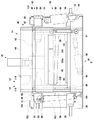
図1は、第1の実施形態に係る断裁装置10の構成を示す斜視図である。断裁装置10は、フレーム12、断裁機構14、テーブルユニット16、テーブル移動機構18、および用紙押さえ機構20を有する。
(First embodiment)
FIG. 1 is a perspective view showing a configuration of a cutting apparatus 10 according to the first embodiment. The cutting device 10 includes a frame 12, a cutting mechanism 14, a table unit 16, a table moving mechanism 18, and a sheet pressing mechanism 20.

図2は、第1の実施形態に係る断裁装置10を図1の視点Pから見た正面図である。断裁機構14は、刃物ユニット22、右上ガイドユニット24、左上ガイドユニット26、下ガイドユニット28、右上水平レール30、左上水平レール32、および下水平レール34を有する。   FIG. 2 is a front view of the cutting apparatus 10 according to the first embodiment viewed from the viewpoint P of FIG. The cutting mechanism 14 includes a blade unit 22, an upper right guide unit 24, an upper left guide unit 26, a lower guide unit 28, an upper right horizontal rail 30, an upper left horizontal rail 32, and a lower horizontal rail 34.

刃物ユニット22は、刃物40、中央プレート42、上プレート44、下プレート46、右垂直レール48、および左垂直レール50を有する。刃物ユニット22は、水平方向および垂直方向に移動可能に設けられており、これにより刃物40は、用紙束を断裁すべく移動可能に設けられる。   The blade unit 22 includes a blade 40, a center plate 42, an upper plate 44, a lower plate 46, a right vertical rail 48, and a left vertical rail 50. The blade unit 22 is provided so as to be movable in the horizontal direction and the vertical direction, whereby the blade 40 is provided so as to be movable so as to cut the sheet bundle.

刃物40は平板状に設けられ、刃先が下方を向くように配置される。第1の実施形態では、刃物40は、刃先が右に行くほど下がるよう設けられる。刃物40の上方は、中央プレート42の下方に固定される。中央プレート42の上方且つ同一面上に上プレート44が配置され、中央プレート42の下方且つ同一面上に下プレート46が配置される。中央プレート42、上プレート44、および下プレート46は、垂直に延在する右垂直レール48によってそれぞれ裏面右側が互いに連結され、垂直に延在する左垂直レール50によってそれぞれ裏面左側が互いに連結されている。   The blade 40 is provided in a flat plate shape and is disposed so that the blade edge faces downward. In the first embodiment, the blade 40 is provided so that the blade edge is lowered as it goes to the right. The upper part of the blade 40 is fixed below the central plate 42. An upper plate 44 is disposed above and on the same surface of the central plate 42, and a lower plate 46 is disposed below and on the same surface of the central plate 42. The center plate 42, the upper plate 44, and the lower plate 46 are connected to each other on the right side by a right vertical rail 48 that extends vertically, and are connected to each other on the left side by a left vertical rail 50 that extends vertically. Yes.

右上ガイドユニット24は、垂直ガイド52、水平ガイド54、およびブロック56を有する。垂直ガイド52は、右垂直レール48が摺動可能に嵌合するよう垂直方向に延びる凹部を有する。右上水平レール30は、水平方向に延在するようフレーム12の前面右上方に固定されている。水平ガイド54は、この右上水平レール30が摺動可能に嵌合するよう水平方向に延びる凹部を有する。垂直ガイド52と水平ガイド54とは互いにブロック56によって結合されている。   The upper right guide unit 24 includes a vertical guide 52, a horizontal guide 54, and a block 56. The vertical guide 52 has a recess extending in the vertical direction so that the right vertical rail 48 is slidably fitted. The upper right horizontal rail 30 is fixed to the upper right of the front surface of the frame 12 so as to extend in the horizontal direction. The horizontal guide 54 has a recess extending in the horizontal direction so that the upper right horizontal rail 30 is slidably fitted. The vertical guide 52 and the horizontal guide 54 are coupled to each other by a block 56.

左上ガイドユニット26は、垂直ガイド58、水平ガイド60、およびブロック62を有する。垂直ガイド58は、左垂直レール50が摺動可能に嵌合するよう垂直方向に延びる凹部を有する。左上水平レール32は、水平方向に延在するようフレーム12の前面左上方に固定されている。水平ガイド60は、この左上水平レール32が摺動可能に嵌合するよう水平方向に延びる凹部を有する。垂直ガイド58と水平ガイド60とは互いにブロック62によって結合されている。また、中央プレート42と下プレート46とは、連結部材47によって互いに結合されている。   The upper left guide unit 26 includes a vertical guide 58, a horizontal guide 60, and a block 62. The vertical guide 58 has a concave portion extending in the vertical direction so that the left vertical rail 50 is slidably fitted. The upper left horizontal rail 32 is fixed to the upper left of the front surface of the frame 12 so as to extend in the horizontal direction. The horizontal guide 60 has a recess extending in the horizontal direction so that the upper left horizontal rail 32 is slidably fitted. The vertical guide 58 and the horizontal guide 60 are coupled to each other by a block 62. Further, the central plate 42 and the lower plate 46 are coupled to each other by a connecting member 47.

下ガイドユニット28は、垂直ガイド64、垂直ガイド66、水平ガイド68、およびブロック70を有する。垂直ガイド64は、右垂直レール48が摺動可能に嵌合するよう垂直方向に延びる凹部を有する。垂直ガイド66は、左垂直レール50が摺動可能に嵌合するよう垂直方向に延びる凹部を有する。下水平レール34は、水平方向に延在するようフレーム12の前面下方に固定されている。水平ガイド68は、この下水平レール34が摺動可能に嵌合するよう水平方向に延びる凹部を有する。垂直ガイド64および垂直ガイド66と水平ガイド68とは、互いにブロック70によって結合されている。   The lower guide unit 28 includes a vertical guide 64, a vertical guide 66, a horizontal guide 68, and a block 70. The vertical guide 64 has a recess extending in the vertical direction so that the right vertical rail 48 is slidably fitted. The vertical guide 66 has a recess extending in the vertical direction so that the left vertical rail 50 is slidably fitted. The lower horizontal rail 34 is fixed below the front surface of the frame 12 so as to extend in the horizontal direction. The horizontal guide 68 has a recess extending in the horizontal direction so that the lower horizontal rail 34 is slidably fitted. The vertical guide 64 and the vertical guide 66 and the horizontal guide 68 are coupled to each other by a block 70.

こうして刃物ユニット22は、垂直ガイド52および垂直ガイド64に右垂直レール48が摺動可能に嵌合し、水平ガイド54および垂直ガイド66が左垂直レール50に摺動可能に嵌合することにより、垂直方向に移動可能に設けられる。以下、刃物40を垂直に移動させるためのこれら垂直ガイド52、垂直ガイド58、垂直ガイド64、垂直ガイド66、右垂直レール48、および左垂直レール50を垂直リニアガイド機構80とする。   In this way, the blade unit 22 is configured such that the right vertical rail 48 is slidably fitted to the vertical guide 52 and the vertical guide 64, and the horizontal guide 54 and the vertical guide 66 are slidably fitted to the left vertical rail 50. It is provided so as to be movable in the vertical direction. Hereinafter, the vertical guide 52, the vertical guide 58, the vertical guide 64, the vertical guide 66, the right vertical rail 48, and the left vertical rail 50 for moving the blade 40 vertically will be referred to as a vertical linear guide mechanism 80.

また、刃物ユニット22は、水平ガイド54、水平ガイド60、および水平ガイド68がそれぞれ右上水平レール30、左上水平レール32、および下水平レール34に摺動可能に嵌合することにより、右上ガイドユニット24、左上ガイドユニット26、および下ガイドユニット28と共に水平方向に移動可能に設けられる。以下、刃物40を水平方向に移動可能とするためのこれら水平ガイド54、水平ガイド60、水平ガイド68、右上水平レール30、左上水平レール32、および下水平レール34を水平リニアガイド機構82とする。   In addition, the blade unit 22 includes a horizontal guide 54, a horizontal guide 60, and a horizontal guide 68 that are slidably fitted to the upper right horizontal rail 30, the upper left horizontal rail 32, and the lower horizontal rail 34, respectively. 24, the upper left guide unit 26, and the lower guide unit 28 are provided so as to be movable in the horizontal direction. Hereinafter, the horizontal guide 54, the horizontal guide 60, the horizontal guide 68, the upper right horizontal rail 30, the upper left horizontal rail 32, and the lower horizontal rail 34 for enabling the blade 40 to move in the horizontal direction are referred to as a horizontal linear guide mechanism 82. .

下プレート46の右端部周辺には、第1油圧シリンダ86の一端が連結される。第1油圧シリンダ86の他端は、フレーム12に連結される。このため、第1油圧シリンダ86を伸縮させることにより、刃物ユニット22を垂直方向に移動させることができる。以下、垂直リニアガイド機構80および第1油圧シリンダ86を、刃物40を垂直方向に駆動する垂直駆動機構90とする。   One end of a first hydraulic cylinder 86 is connected to the periphery of the right end portion of the lower plate 46. The other end of the first hydraulic cylinder 86 is connected to the frame 12. For this reason, the blade unit 22 can be moved in the vertical direction by expanding and contracting the first hydraulic cylinder 86. Hereinafter, the vertical linear guide mechanism 80 and the first hydraulic cylinder 86 are referred to as a vertical drive mechanism 90 that drives the blade 40 in the vertical direction.

下プレート46の裏面略中央には、第2油圧シリンダ88の一端が連結される。第2油圧シリンダ88の他端は、フレーム12に連結される。このため、第2油圧シリンダ88を伸縮させることにより、刃物ユニット22を水平方向に移動させることができる。以下、水平リニアガイド機構82および第2油圧シリンダ88を、刃物40を水平方向に駆動する水平駆動機構92とする。   One end of a second hydraulic cylinder 88 is connected to the center of the back surface of the lower plate 46. The other end of the second hydraulic cylinder 88 is connected to the frame 12. For this reason, the blade unit 22 can be moved in the horizontal direction by expanding and contracting the second hydraulic cylinder 88. Hereinafter, the horizontal linear guide mechanism 82 and the second hydraulic cylinder 88 are referred to as a horizontal drive mechanism 92 that drives the blade 40 in the horizontal direction.

ブロック62には、フック103が取り付けられている。また、下プレート46の左端部には、フック104が取り付けられている。このフック103およびフック104の各々に、コイルスプリング102の両端部のそれぞれが係止される。このようにコイルスプリング102が設けられることにより、刃物ユニット22に対し上方に持ち上げる力を与え、第1油圧シリンダ86が刃物ユニット22を上方に駆動するときの駆動力をアシストしている。   A hook 103 is attached to the block 62. A hook 104 is attached to the left end of the lower plate 46. The hook 103 and the hook 104 are respectively engaged with both ends of the coil spring 102. By providing the coil spring 102 in this way, a force for lifting the blade unit 22 is given, and the first hydraulic cylinder 86 assists the driving force when the blade unit 22 is driven upward.

断裁装置10は、各種演算処理を実行するCPU、各種制御プログラムを格納するROM、データ格納やプログラム実行のためのワークエリアとして利用されるRAMなどを有する電子制御部(図示せず)を内部に有している。電子制御部は、第1油圧シリンダ86および第2油圧シリンダ88の各々の作動を制御することにより、垂直駆動機構90および水平駆動機構92の各々の作動を制御する。第1の実施形態では、電子制御部は、垂直駆動機構90および水平駆動機構92の双方で刃物40を駆動して刃物40に用紙束を断裁させる。刃物40の詳細な駆動方法については後述する。   The cutting apparatus 10 includes an electronic control unit (not shown) having a CPU that executes various arithmetic processes, a ROM that stores various control programs, a RAM that is used as a work area for data storage and program execution, and the like. Have. The electronic control unit controls the operations of the vertical drive mechanism 90 and the horizontal drive mechanism 92 by controlling the operations of the first hydraulic cylinder 86 and the second hydraulic cylinder 88, respectively. In the first embodiment, the electronic control unit drives the blade 40 with both the vertical drive mechanism 90 and the horizontal drive mechanism 92 to cause the blade 40 to cut the sheet bundle. A detailed driving method of the blade 40 will be described later.

フレーム12の右上部分は、右位置センサ120が固定されている。また、フレーム12の左上部分には、左位置センサ122が固定されている。右位置センサ120は、右上ガイドユニット24を検知することにより、刃物40が許容される最右位置に到達したことを検知する。左位置センサ122は、左上ガイドユニット26を検知することにより、刃物40が許容される最左位置に到達したことを検知する。   The right position sensor 120 is fixed to the upper right portion of the frame 12. A left position sensor 122 is fixed to the upper left portion of the frame 12. The right position sensor 120 detects that the cutting tool 40 has reached the allowable rightmost position by detecting the upper right guide unit 24. The left position sensor 122 detects that the blade 40 has reached the allowable leftmost position by detecting the upper left guide unit 26.

また、フレーム12の上方には、上位置センサ116および下位置センサ118が固定されている。上位置センサ116は下位置センサ118よりも上方に配置されている。上位置センサ116は、上プレート44の上端を検知することにより、刃物40が許容される最上位置に到達したことを検知する。下位置センサ118は、上プレート44の上端を検知することにより、刃物40が許容される最下位置に到達したことを検知する。   An upper position sensor 116 and a lower position sensor 118 are fixed above the frame 12. The upper position sensor 116 is disposed above the lower position sensor 118. The upper position sensor 116 detects that the blade 40 has reached the uppermost position allowed by detecting the upper end of the upper plate 44. The lower position sensor 118 detects that the blade 40 has reached the lowest position allowed by detecting the upper end of the upper plate 44.

フレーム12の下方中央には、断裁テーブル124が水平に広がるよう配置される。断裁テーブル124の上面には、用紙束が載置されるべき載置面124aが設けられる。   A cutting table 124 is disposed in the lower center of the frame 12 so as to spread horizontally. On the upper surface of the cutting table 124, a placement surface 124a on which a sheet bundle is to be placed is provided.

中央プレート42の裏面右側には、垂直に延在するガイドバー98が固定されている。このガイドバー98の裏面と接するよう、ガイドブロック94が断裁テーブル124の右側に固定されている。また、中央プレート42の裏面左側には、垂直に延在するガイドバー100が固定されている。このガイドバー100の裏面と接するよう、ガイドブロック96が断裁テーブル124の左側に固定されている。刃物40が上下左右に移動するとき、ガイドバー98およびガイドバー100の各々は、それぞれガイドブロック94およびガイドブロック96と摺動し、刃物40の前後方向の動きを規制する。   A vertically extending guide bar 98 is fixed to the right side of the back surface of the center plate 42. A guide block 94 is fixed to the right side of the cutting table 124 so as to contact the back surface of the guide bar 98. A guide bar 100 extending vertically is fixed to the left side of the back surface of the center plate 42. A guide block 96 is fixed to the left side of the cutting table 124 so as to contact the back surface of the guide bar 100. When the blade 40 moves vertically and horizontally, each of the guide bar 98 and the guide bar 100 slides with the guide block 94 and the guide block 96, respectively, and restricts the movement of the blade 40 in the front-rear direction.

図3は、第1の実施形態に係る断裁装置10を図1の視点Qから見た裏面図である。用紙押さえ機構20は、押さえ部材130、中継部材132、連結部材134、第3油圧シリンダ136、およびリニアガイド140を有する。押さえ部材130は、平板をL字状に折り曲げた形状に形成される。押さえ部材130は、一方の外面が下方に向くように配置される。この下方に向く外面が、用紙束を断裁テーブル124の載置面124aに押し付ける押圧面130aとなる。   FIG. 3 is a rear view of the cutting apparatus 10 according to the first embodiment as viewed from the viewpoint Q of FIG. The sheet pressing mechanism 20 includes a pressing member 130, a relay member 132, a connecting member 134, a third hydraulic cylinder 136, and a linear guide 140. The pressing member 130 is formed in a shape obtained by bending a flat plate into an L shape. The pressing member 130 is disposed such that one outer surface faces downward. The outer surface facing downward is a pressing surface 130 a that presses the sheet bundle against the mounting surface 124 a of the cutting table 124.

第3油圧シリンダ136はフレーム12の上方部分に固定される。中継部材132および連結部材134は、押さえ部材130と第3油圧シリンダ136とを連結する。リニアガイド140は、垂直方向に移動するよう押さえ部材130を案内する。具体的には、リニアガイド140は、レール142およびガイド144を有する。レール142は、押さえ部材130および中継部材132の双方に垂直方向に延在するよう固定される。レール142は、押さえ部材130に対向するフレーム12に固定されている。ガイド144は、レール142が摺動可能に嵌合する凹部が設けられている。レール142がガイド144に嵌合することにより、リニアガイド140は押さえ部材130を垂直方向に移動するよう案内する。   The third hydraulic cylinder 136 is fixed to the upper part of the frame 12. The relay member 132 and the connecting member 134 connect the pressing member 130 and the third hydraulic cylinder 136. The linear guide 140 guides the pressing member 130 to move in the vertical direction. Specifically, the linear guide 140 includes a rail 142 and a guide 144. The rail 142 is fixed to both the pressing member 130 and the relay member 132 so as to extend in the vertical direction. The rail 142 is fixed to the frame 12 facing the pressing member 130. The guide 144 is provided with a recess in which the rail 142 is slidably fitted. When the rail 142 is fitted into the guide 144, the linear guide 140 guides the pressing member 130 to move in the vertical direction.

以上より、第3油圧シリンダ136が伸縮することにより、押さえ部材130が垂直方向に駆動される。具体的には、第3油圧シリンダ136が伸長することにより、押さえ部材130が下降し、断裁テーブル124の載置面124aに載置された用紙束を下方に押し付ける。第3油圧シリンダ136が収縮することにより、押さえ部材130が上昇し、この用紙束への押し付け力が解除される。   As described above, when the third hydraulic cylinder 136 expands and contracts, the pressing member 130 is driven in the vertical direction. Specifically, when the third hydraulic cylinder 136 is extended, the pressing member 130 is lowered to press the sheet bundle placed on the placement surface 124a of the cutting table 124 downward. When the third hydraulic cylinder 136 contracts, the pressing member 130 rises, and the pressing force against the sheet bundle is released.

図4は、第1の実施形態に係る断裁装置10を図1の視点Rから見た左側面図である。テーブルユニット16は、載置テーブル170、支持ブラケット172、固定機構174、および回転機構176を有する。載置テーブル170は、用紙束が載置される載置面170aを有する。載置テーブル170は、載置面170aに垂直な軸を中心に回転可能に支持ブラケット172に支持される。   4 is a left side view of the cutting apparatus 10 according to the first embodiment as viewed from the viewpoint R of FIG. The table unit 16 includes a mounting table 170, a support bracket 172, a fixing mechanism 174, and a rotating mechanism 176. The placement table 170 has a placement surface 170a on which a sheet bundle is placed. The mounting table 170 is supported by the support bracket 172 so as to be rotatable about an axis perpendicular to the mounting surface 170a.

固定機構174は、載置テーブル170に載置された用紙束のいずれかの端縁周辺を載置テーブル170に固定する固定手段として機能する。固定機構174は、載置テーブル170の一端縁周辺の上面に設けられる。固定機構174は、クランパ180、ロッド182、エアシリンダ184、および位置決めピン186を有する。位置決めピン186は載置テーブル170の一端縁周辺の上面に、その一端縁に平行に2つ並設される。位置決めピン186は、載置テーブル170に載置される用紙束の一方向の位置を規制する位置決め部材として機能する。載置テーブル170に冊子が載置される場合、位置決めピン186には冊子の背が突き当てられて位置決めされる。   The fixing mechanism 174 functions as a fixing unit that fixes the periphery of any edge of the sheet bundle placed on the placement table 170 to the placement table 170. The fixing mechanism 174 is provided on the upper surface around one end edge of the mounting table 170. The fixing mechanism 174 includes a clamper 180, a rod 182, an air cylinder 184, and a positioning pin 186. Two positioning pins 186 are arranged in parallel on the upper surface of one end edge of the mounting table 170 in parallel to the one end edge. The positioning pin 186 functions as a positioning member that regulates the position in one direction of the sheet bundle placed on the placement table 170. When the booklet is placed on the placement table 170, the booklet spine is abutted against the positioning pin 186 and positioned.

エアシリンダ184は、位置決めピン186と載置テーブル170の一端縁との間に配置される。ロッド182は、エアシリンダ184から垂直に上方に延在する。エアシリンダ184は、ロッド182を軸方向、すなわち垂直方向に移動させる。クランパ180は断面がL字状に形成され、一方の内面がロッド182の上端に固定されている。以上より、エアシリンダ184が収縮することにより、ロッド182と共にクランパ180が下降し、載置テーブル170に載置された用紙束を下方に押し付けて固定する。したがって、載置テーブル170に冊子が載置された場合、固定機構174は冊子の背周辺を固定する。   The air cylinder 184 is disposed between the positioning pin 186 and one end edge of the mounting table 170. The rod 182 extends vertically upward from the air cylinder 184. The air cylinder 184 moves the rod 182 in the axial direction, that is, in the vertical direction. The clamper 180 has an L-shaped cross section, and one inner surface is fixed to the upper end of the rod 182. As described above, when the air cylinder 184 contracts, the clamper 180 moves down together with the rod 182, and the sheet bundle placed on the placement table 170 is pressed downward and fixed. Therefore, when the booklet is placed on the placement table 170, the fixing mechanism 174 fixes the periphery of the booklet back.

テーブル移動機構18は、フレーム200、ボールネジ202、およびモータ204を有する。フレーム200は、断裁装置10の前後方向(以下、単に「前後方向」という)に延在して設けられる。フレーム200には前後方向に延在するガイド(図示せず)が設けられており、テーブルユニット16の支持ブラケット172は、このガイドに摺動可能に支持されている。フレーム200は、こうして載置テーブル170の載置面170aが水平となり且つ前後方向に摺動できるようテーブルユニット16全体を支持する。   The table moving mechanism 18 includes a frame 200, a ball screw 202, and a motor 204. The frame 200 is provided so as to extend in the front-rear direction (hereinafter simply referred to as “front-rear direction”) of the cutting apparatus 10. The frame 200 is provided with a guide (not shown) extending in the front-rear direction, and the support bracket 172 of the table unit 16 is slidably supported by the guide. The frame 200 thus supports the entire table unit 16 so that the placement surface 170a of the placement table 170 becomes horizontal and can slide in the front-rear direction.

ボールネジ202は、前後方向に延在するよう配置され、回転可能にフレーム200に支持される。支持ブラケット172は、ボールネジ202と噛み合う雌ネジ部(図示せず)が設けられており、ボールネジ202が回転することによりテーブルユニット16全体が前後方向に移動することが可能となっている。フレーム200の後部にはモータ204が固定されている。モータ204は、ボールネジ202を駆動するよう、ボールネジ202の一端に接続されている。電子制御部は、モータ204の作動を制御することにより、テーブルユニット16の前後方向への移動を制御する。   The ball screw 202 is disposed so as to extend in the front-rear direction and is rotatably supported by the frame 200. The support bracket 172 is provided with a female screw portion (not shown) that meshes with the ball screw 202, and the entire table unit 16 can be moved in the front-rear direction when the ball screw 202 rotates. A motor 204 is fixed to the rear portion of the frame 200. The motor 204 is connected to one end of the ball screw 202 so as to drive the ball screw 202. The electronic control unit controls the movement of the table unit 16 in the front-rear direction by controlling the operation of the motor 204.

回転機構176は、載置テーブル170を載置面170aと垂直な軸を中心に回転させる。載置テーブル170の具体的な構成については後述する。回転機構176は、1つの用紙束を複数回にわたって複数個所を断裁するときの各々の断裁タイミングの間に、断裁すべき個所を切り替えるべく載置テーブル170を回転させて周方向位置を切り替える。電子制御部および回転機構176は、載置テーブル170に冊子が載置された場合、天地の一方、小口、天地の他方の順に刃物40で断裁して切りそろえるよう、載置テーブル170の周方向位置を順次切り替える。   The rotation mechanism 176 rotates the mounting table 170 around an axis perpendicular to the mounting surface 170a. A specific configuration of the mounting table 170 will be described later. The rotation mechanism 176 rotates the mounting table 170 to switch the position in the circumferential direction so as to switch the portion to be cut during each cutting timing when cutting a plurality of locations of a single sheet bundle a plurality of times. When the booklet is placed on the placement table 170, the electronic control unit and the rotation mechanism 176 are positioned in the circumferential direction of the placement table 170 so that the blade 40 cuts and trims the booklet in the order of one of the top, the bottom, and the other. Switch sequentially.

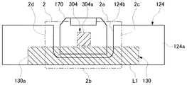
図5(a)は、天地の一方を断裁するときの冊子2、固定機構174、および刃先移動面L1との関係を示す図である。刃物40は、用紙束を断裁すべく移動可能に設けられる。このときの刃物40の刃先の移動経路を刃先移動面L1とする。冊子2は、刃物40によってこの刃先移動面L1に沿って断裁される。   Fig.5 (a) is a figure which shows the relationship between the booklet 2, the fixing mechanism 174, and the blade edge | tip moving surface L1 when cutting one side of the top and bottom. The blade 40 is movably provided to cut the sheet bundle. The moving path of the blade edge of the blade 40 at this time is defined as a blade edge moving surface L1. The booklet 2 is cut along the blade edge moving surface L1 by the blade 40.

この例では、固定機構174が右に位置するよう載置テーブル170の周方向位置が保持されているときに、固定機構174に固定されている背2aに接する隣接端縁である天2cが前方、他の隣接端縁である地2dが後方に位置するよう冊子2が載置テーブル170に固定されているものとする。このとき、背2aの背向端縁である小口2bは左側に位置する。なお、天2cと地2dの向きが逆でもよい。   In this example, when the circumferential direction position of the mounting table 170 is held so that the fixing mechanism 174 is positioned on the right, the top 2c that is an adjacent edge in contact with the spine 2a fixed to the fixing mechanism 174 is forward. It is assumed that the booklet 2 is fixed to the placement table 170 so that the ground 2d that is another adjacent edge is located rearward. At this time, the fore edge 2b which is the back edge of the back 2a is located on the left side. The directions of the top 2c and the ground 2d may be reversed.

電子制御部は、載置テーブル170に載置された冊子を最初に断裁する場合、固定機構174が冊子の右側に位置するよう回転機構176を用いて載置テーブル170を回転させる。このため、天2cが刃先移動面L1を越え、天2cが最初の断裁対象となる。   When the booklet placed on the placement table 170 is first cut, the electronic control unit rotates the placement table 170 using the rotation mechanism 176 so that the fixing mechanism 174 is positioned on the right side of the booklet. For this reason, the top 2c exceeds the cutting edge moving surface L1, and the top 2c is the first cutting target.

図5(b)は、天地の一方を断裁すべく刃物40が初期位置にあるときの断裁機構14を示す図である。電子制御部は、天2cまたは地2dを断裁して除去する場合、背2aから小口2bに向かう方向に刃物40を移動させて用紙束を断裁するよう、垂直駆動機構90および水平駆動機構92の各々の作動を制御する。このため、電子制御部は、冊子2を断裁する前、すなわち刃物40が冊子2よりも上方にあるときに、中央位置より背2a側の右の初期位置で刃物40を保持する。第1の実施形態では、刃物40が最上位置且つ最右位置にあるときがこの初期位置となる。   FIG.5 (b) is a figure which shows the cutting mechanism 14 when the cutter 40 exists in an initial position to cut one side of the top and bottom. When the electronic control unit cuts and removes the top 2c or the ground 2d, the vertical drive mechanism 90 and the horizontal drive mechanism 92 are arranged so as to cut the sheet bundle by moving the blade 40 in the direction from the back 2a toward the fore edge 2b. Control each operation. For this reason, the electronic control unit holds the cutter 40 at the right initial position on the back 2a side from the center position before cutting the booklet 2, that is, when the cutter 40 is above the booklet 2. In the first embodiment, the initial position is when the blade 40 is in the uppermost position and the rightmost position.

図5(c)は、天地の一方を断裁すべく刃物40が下降位置に下降したときの断裁機構14を示す図である。電子制御部は、背2aから小口2bに向かう方向、すなわち右から左に移動させながら刃物40を下降させるよう、垂直駆動機構90および水平駆動機構92の作動を制御する。第1の実施形態では、最下位置且つ最左位置に向けて直線的に刃物40を移動させる。このように背2aから小口2bに向けて移動させながら刃物40を下降させることにより、断裁後の冊子2の美観低下を抑制することができる。   FIG.5 (c) is a figure which shows the cutting mechanism 14 when the cutter 40 descend | falls to the lowered position so that one of the top and bottom may be cut. The electronic control unit controls the operation of the vertical drive mechanism 90 and the horizontal drive mechanism 92 so as to lower the blade 40 while moving from the back 2a toward the fore edge 2b, that is, from right to left. In the first embodiment, the blade 40 is linearly moved toward the lowest position and the leftmost position. By lowering the blade 40 while moving from the spine 2a toward the fore edge 2b in this way, it is possible to suppress a decrease in the beauty of the booklet 2 after cutting.

図6(a)は、小口を断裁するときの冊子2、固定機構174、および刃先移動面L1との関係を示す図である。電子制御部は、載置テーブル170に載置された冊子を次に断裁する場合、固定機構174が冊子の後方に位置するよう回転機構176を用いて載置テーブル170を回転させる。このため、小口2bが刃先移動面L1を越え、小口2bが次の断裁対象となる。   FIG. 6A is a diagram illustrating a relationship between the booklet 2, the fixing mechanism 174, and the blade edge moving surface L1 when cutting the fore edge. When the booklet placed on the placement table 170 is cut next, the electronic control unit rotates the placement table 170 using the rotation mechanism 176 so that the fixing mechanism 174 is positioned behind the booklet. For this reason, the fore edge 2b exceeds the cutting edge moving surface L1, and the fore edge 2b becomes the next cutting object.

図6(b)は、小口を断裁すべく刃物40が初期位置にあるときの断裁機構14を示す図である。第1の実施形態では、小口2bを断裁する場合、刃物40を右から左に移動させながら下降させる。このため、電子制御部は、天2cの断裁前と同様に、小口2bを断裁する前に、冊子2よりも上方且つ中央位置より右の初期位置で刃物40を保持する。第1の実施形態では、刃物40が最上位置且つ最右位置にあるときがこの初期位置となる。   FIG. 6B is a view showing the cutting mechanism 14 when the blade 40 is in the initial position to cut the fore edge. In the first embodiment, when cutting the fore edge 2b, the blade 40 is lowered while moving from the right to the left. For this reason, the electronic control unit holds the blade 40 at an initial position above the booklet 2 and on the right of the center position before cutting the fore edge 2b, similarly to before cutting the top 2c. In the first embodiment, the initial position is when the blade 40 is in the uppermost position and the rightmost position.

この初期位置に刃物40を保持するため、電子制御部は、天2cの断裁工程の終了後、小口2bの断裁工程で移動を開始すべき初期位置まで刃物40を移動させるよう、垂直駆動機構90および水平駆動機構92の各々の作動を制御する。このとき電子制御部は、図5(c)に示す位置から図6(b)に示す位置まで直線的に刃物40を移動させる。   In order to hold the blade 40 in this initial position, the electronic control unit 90 moves the blade 40 to the initial position where movement should be started in the cutting process of the fore edge 2b after the cutting process of the top 2c. And the operation of each of the horizontal drive mechanisms 92 is controlled. At this time, the electronic control unit linearly moves the blade 40 from the position shown in FIG. 5C to the position shown in FIG.

図6(c)は、小口を断裁すべく刃物40が下降位置に下降したときの断裁機構14を示す図である。電子制御部は、刃物40を右から左に移動させながら下降させるよう、垂直駆動機構90および水平駆動機構92の作動を制御する。このように小口2bを断裁する場合にも刃物40を斜めに移動させることにより、断裁後の冊子2の美観低下を抑制することができる。第1の実施形態では、最下位置且つ最左位置に向けて直線的に刃物40を移動させる。   FIG.6 (c) is a figure which shows the cutting mechanism 14 when the blade 40 descend | falls to a lowered position to cut a fore edge. The electronic control unit controls the operations of the vertical drive mechanism 90 and the horizontal drive mechanism 92 so as to lower the blade 40 while moving it from the right to the left. Thus, even when cutting the edge 2b, the aesthetic loss of the booklet 2 after cutting can be suppressed by moving the blade 40 diagonally. In the first embodiment, the blade 40 is linearly moved toward the lowest position and the leftmost position.

なお、電子制御部は、刃物40を左から右に移動させながら下降させるよう垂直駆動機構90および水平駆動機構92の作動を制御してもよい。この場合、電子制御部は、小口2bを断裁する前に、冊子2よりも上方且つ中央位置より左の初期位置で刃物40を保持する。第1の実施形態では、刃物40が最上位置且つ最左位置にあるときがこの初期位置となる。   The electronic control unit may control the operations of the vertical drive mechanism 90 and the horizontal drive mechanism 92 so as to lower the blade 40 while moving it from the left to the right. In this case, the electronic control unit holds the blade 40 at an initial position above the booklet 2 and to the left of the center position before cutting the fore edge 2b. In the first embodiment, the initial position is when the blade 40 is at the uppermost position and the leftmost position.

図7(a)は、天地の他方を断裁するときの冊子2、固定機構174、および刃先移動面L1との関係を示す図である。電子制御部は、載置テーブル170に載置された冊子を次に断裁する場合、固定機構174が冊子の左側に位置するよう回転機構176を用いて載置テーブル170を回転させる。このため、地2dが刃先移動面L1を越え、地2dが次の断裁対象となる。   Fig.7 (a) is a figure which shows the relationship between the booklet 2, the fixing mechanism 174, and the blade edge | tip moving surface L1 when cutting the other top and bottom. When the booklet placed on the placement table 170 is cut next, the electronic control unit rotates the placement table 170 using the rotation mechanism 176 so that the fixing mechanism 174 is positioned on the left side of the booklet. For this reason, the ground 2d exceeds the cutting edge moving surface L1, and the ground 2d becomes the next cutting object.

図7(b)は、天地の他方を断裁すべく刃物40が初期位置にあるときの断裁機構14を示す図である。電子制御部は、背2aから小口2bに向かう方向に刃物40を移動させて用紙束を断裁するために、冊子2を断裁する前、すなわち刃物40が冊子2よりも上方にあるときに、中央位置より背2a側の左の初期位置で刃物40を保持する。   FIG. 7B is a diagram showing the cutting mechanism 14 when the blade 40 is in the initial position to cut the other of the top and bottom. The electronic control unit moves the blade 40 in the direction from the spine 2a toward the fore edge 2b and cuts the sheet bundle before cutting the booklet 2, that is, when the blade 40 is above the booklet 2, The blade 40 is held at the initial position on the left side of the back 2a from the position.

この初期位置に刃物40を保持するため、電子制御部は、小口2bの断裁工程の終了後、地2dの断裁工程で移動を開始すべき初期位置まで刃物40を移動させるよう、垂直駆動機構90および水平駆動機構92の各々の作動を制御する。このとき電子制御部は、図6(c)に示す位置から図7(b)に示す位置まで直線的に刃物40を移動させる。   In order to hold the cutter 40 in this initial position, the electronic control unit 90 moves the cutter 40 to the initial position where movement should be started in the cutting process of the ground 2d after the cutting process of the edge 2b. And the operation of each of the horizontal drive mechanisms 92 is controlled. At this time, the electronic control unit linearly moves the blade 40 from the position shown in FIG. 6C to the position shown in FIG.

このように電子制御部は、用紙束を断裁する第1の工程の次に第1の工程とは異なる方向に刃物40を移動させて用紙束を断裁する第2の工程に進む場合、第1の工程の終了後、第2の工程で移動を開始すべき初期位置まで刃物40を移動させて待機させるよう、垂直駆動機構90および水平駆動機構92の各々の作動を制御する。これにより、用紙束を断裁する次の工程に速やかに以降することが可能となる。   As described above, when the electronic control unit proceeds to the second step of cutting the sheet bundle by moving the blade 40 in the direction different from the first step after the first step of cutting the sheet bundle, the first step is performed. After the above process is completed, the operations of the vertical drive mechanism 90 and the horizontal drive mechanism 92 are controlled so that the blade 40 is moved to the initial position where the movement is to be started in the second process and waits. As a result, it is possible to promptly proceed to the next step of cutting the sheet bundle.

図7(c)は、天地の他方を断裁すべく刃物40が下降位置に下降したときの断裁機構14を示す図である。電子制御部は、背2aから小口2bに向かう方向、すなわちこの場合は刃物40を左から右に移動させながら下降させるよう、垂直駆動機構90および水平駆動機構92の作動を制御する。第1の実施形態では、最下位置且つ最右位置に向けて直線的に刃物40を移動させる。   FIG.7 (c) is a figure which shows the cutting mechanism 14 when the blade 40 descend | falls to the lowered position so that the other top and bottom may be cut. The electronic control unit controls the operations of the vertical drive mechanism 90 and the horizontal drive mechanism 92 so as to lower the blade 40 while moving the blade 40 from the left to the right, that is, in the direction from the back 2a to the fore edge 2b. In the first embodiment, the blade 40 is moved linearly toward the lowest position and the rightmost position.

このように電子制御部は、天地の一方を断裁すべき第1の周方向位置に載置テーブル170が保持されているとき、第1の周方向位置から180°回転した周方向位置、すなわち天地の他方を断裁すべき第2の周方向位置に載置テーブル170が保持されているときとは、用紙束の紙面と平行な移動方向が逆方向となる方向に刃物40を移動させて用紙束を断裁するよう、垂直駆動機構90および水平駆動機構92の各々の作動を制御する。載置テーブル170が回転して冊子2の位置を切り替えて、冊子2の天地を断裁する場合、背2aから小口2bに向く方向は天2cを断裁するときと地2dを断裁するときとで異なることになる。これにより、天2cまたは地2dを断裁するときに、刃物40を背2aから小口2bに向けて適切に移動させながら断裁することができる。   As described above, when the mounting table 170 is held at the first circumferential position where one of the top and bottom is to be cut, the electronic control unit rotates the circumferential position 180 degrees from the first circumferential position, that is, the top and bottom. When the mounting table 170 is held at the second circumferential position where the other of the paper sheets is to be cut, the blade 40 is moved in a direction in which the moving direction parallel to the paper surface of the paper bundle is opposite to the paper bundle. The operation of each of the vertical drive mechanism 90 and the horizontal drive mechanism 92 is controlled so as to cut the line. When the placement table 170 rotates and switches the position of the booklet 2 to cut the top and bottom of the booklet 2, the direction from the back 2a to the fore edge 2b differs between when cutting the top 2c and when cutting the ground 2d. It will be. Thereby, when cutting the top 2c or the ground 2d, the cutting tool 40 can be cut while appropriately moving from the spine 2a toward the fore edge 2b.

また、このように電子制御部は、第1の周方向位置に載置テーブル170が保持されているとき、第2の周方向位置に載置テーブル170が保持されているときとは異なる方向に刃物40を移動させて用紙束を断裁するよう、垂直駆動機構90および水平駆動機構92の各々の作動を制御する。これにより、断裁後の冊子2の美観低下を適切に抑制することができる。   Further, in this way, the electronic control unit has a direction different from that when the mounting table 170 is held at the second circumferential position when the mounting table 170 is held at the first circumferential position. The operation of each of the vertical drive mechanism 90 and the horizontal drive mechanism 92 is controlled so that the blade 40 is moved to cut the sheet bundle. Thereby, the fall of the aesthetics of the booklet 2 after cutting can be suppressed appropriately.

図8は、テーブルユニット16を図4の視点Sから見た図である。回転機構176は、載置テーブル170が断裁位置と退避位置との間で移動するときの中途部に設けられる。回転機構176は、スプロケット220、チェーン222、および噛合切替機構224を有する。スプロケット220は、載置テーブル170と共に移動および回転するよう載置テーブル170に連結されている。したがってスプロケット220は、載置テーブル170と共に回転する回転部材として機能する。チェーン222は、スプロケット220と噛み合う噛合部材として機能する。チェーン222は、載置テーブル170の移動中にスプロケット220に噛み合うことによって載置テーブル170を回転させるよう配置される。   FIG. 8 is a view of the table unit 16 as viewed from the viewpoint S of FIG. The rotation mechanism 176 is provided in the middle of the placement table 170 when it moves between the cutting position and the retracted position. The rotation mechanism 176 includes a sprocket 220, a chain 222, and a meshing switching mechanism 224. The sprocket 220 is connected to the mounting table 170 so as to move and rotate together with the mounting table 170. Accordingly, the sprocket 220 functions as a rotating member that rotates together with the mounting table 170. The chain 222 functions as a meshing member that meshes with the sprocket 220. The chain 222 is arranged to rotate the mounting table 170 by meshing with the sprocket 220 during the movement of the mounting table 170.

テーブル移動機構18は、載置された用紙束が断裁されるべき断裁位置と、断裁位置よりも刃先移動面L1から離間した退避位置と、の間で載置テーブル170を移動させる。噛合切替機構224は、断裁位置と退避位置との間で載置テーブル170が移動しているときにスプロケット220と噛み合う噛合位置と、断裁位置と退避位置との間で載置テーブル170が移動してもスプロケット220と噛み合わない非噛合位置と、の間でチェーン222を進退させる。   The table moving mechanism 18 moves the placement table 170 between a cutting position at which the placed sheet bundle is to be cut and a retreat position that is further away from the blade edge moving surface L1 than the cutting position. In the mesh switching mechanism 224, the placement table 170 moves between the meshing position that engages with the sprocket 220, the cutting position, and the withdrawal position when the placement table 170 moves between the cutting position and the withdrawal position. However, the chain 222 is moved back and forth between the non-engagement position where it does not mesh with the sprocket 220.

具体的には、噛合切替機構224は、エアシリンダ226、ロッド228、スライダ230、およびレール232を有する。スライダ230は、ロッド228の両端にそれぞれ固定される。この一対のスライダ230は互いに平行となるよう、ロッド228に垂直に固定される。   Specifically, the mesh switching mechanism 224 includes an air cylinder 226, a rod 228, a slider 230, and a rail 232. The sliders 230 are fixed to both ends of the rod 228, respectively. The pair of sliders 230 are fixed vertically to the rod 228 so as to be parallel to each other.

レール232は、この一対のスライダ230の各々と摺動可能に嵌合するよう一対設けられる。一対のレール232は、テーブル移動機構18のフレーム200に固定される。このときレール232は、テーブルユニット16の移動方向と垂直にスライダ230を摺動させるため、テーブルユニット16の移動方向に対し垂直となるようフレーム200に取り付けられる。   A pair of rails 232 are provided so as to be slidably fitted to each of the pair of sliders 230. The pair of rails 232 are fixed to the frame 200 of the table moving mechanism 18. At this time, the rail 232 is attached to the frame 200 so as to be perpendicular to the moving direction of the table unit 16 in order to slide the slider 230 perpendicular to the moving direction of the table unit 16.

一対のスライダ230の各々の先端には、チェーン222の端部が固定される。ロッド228はエアシリンダ226に連結される。以上より、スプロケット220が噛合切替機構224の近傍を通過するときにエアシリンダ226を伸長させることにより、チェーン222をスプロケット220に噛み合わせて載置テーブル170を回転させることができる。   The end of the chain 222 is fixed to the tip of each of the pair of sliders 230. The rod 228 is connected to the air cylinder 226. As described above, by extending the air cylinder 226 when the sprocket 220 passes in the vicinity of the mesh switching mechanism 224, the mounting table 170 can be rotated by meshing the chain 222 with the sprocket 220.

このように回転機構176は、載置テーブル170が移動する力を利用して載置テーブル170を回転させる。載置テーブル170には重い冊子なども載置されることもあるため、載置テーブル170を回転させるための駆動源を別途設ける場合は、この駆動源の小型化は困難を伴う。第1の実施形態に係る回転機構176によれば、載置テーブル170を回転させるための駆動源を別途設ける場合に比べてコストを抑制することができる。   As described above, the rotation mechanism 176 rotates the mounting table 170 using the force by which the mounting table 170 moves. Since a heavy booklet or the like may be placed on the placement table 170, if a drive source for rotating the placement table 170 is separately provided, it is difficult to reduce the size of the drive source. According to the rotation mechanism 176 according to the first embodiment, it is possible to reduce the cost as compared with a case where a drive source for rotating the mounting table 170 is separately provided.

なお、テーブル移動機構18は、断裁位置センサ240および退避位置センサ242を有する。断裁位置センサ240は、テーブルユニット16の支持ブラケット172が断裁位置センサ240に当接したときに、載置された用紙束が断裁されるべき断裁位置に載置テーブル170が進出したことを検出する。退避位置センサ242は、支持ブラケット172が退避位置センサ242に当接したときに、断裁位置よりも刃先移動面L1から離間した退避位置に載置テーブル170が退避したことを検出する。断裁位置センサ240および退避位置センサ242の検出結果は、電子制御部に入力される。   The table moving mechanism 18 includes a cutting position sensor 240 and a retracted position sensor 242. The cutting position sensor 240 detects that the placement table 170 has advanced to a cutting position where the placed sheet bundle should be cut when the support bracket 172 of the table unit 16 contacts the cutting position sensor 240. . The retreat position sensor 242 detects that the placement table 170 has retreated to a retreat position that is farther from the cutting edge moving surface L1 than the cutting position when the support bracket 172 contacts the retraction position sensor 242. The detection results of the cutting position sensor 240 and the retracted position sensor 242 are input to the electronic control unit.

図9は、図4のテーブルユニット16周辺の拡大図である。回転機構176は、ロック機構250をさらに有する。ロック機構250は、位置決めロータ252、位置決めピン254、およびエアシリンダ256を有する。   FIG. 9 is an enlarged view around the table unit 16 of FIG. The rotation mechanism 176 further includes a lock mechanism 250. The lock mechanism 250 includes a positioning rotor 252, a positioning pin 254, and an air cylinder 256.

位置決めロータ252は円盤状に形成され、スプロケット220と同軸となるようスプロケット220に固定される。位置決めロータ252の外周には、周方向の間隔が互いに90°の角度となるよう設けられた3つの切り欠き部252aが設けられている。位置決めピン254は、一端が位置決めロータ252の外周に対向し、他端がエアシリンダ256に連結されている。エアシリンダ256は、支持ブラケット172に固定される。   The positioning rotor 252 is formed in a disk shape and is fixed to the sprocket 220 so as to be coaxial with the sprocket 220. On the outer periphery of the positioning rotor 252, there are provided three cutout portions 252 a provided so that the circumferential interval is an angle of 90 °. The positioning pin 254 has one end facing the outer periphery of the positioning rotor 252 and the other end connected to the air cylinder 256. The air cylinder 256 is fixed to the support bracket 172.

したがって、エアシリンダ256を伸長させたときは、位置決めピン254が位置決めロータ252の外周に向けて進出する。位置決めロータ252は、位置決めピン254が切り欠き部252aに嵌合した位置でロックされる。こうしてロック機構250は、回転する載置テーブル170を所定の周方向位置でロックする。   Therefore, when the air cylinder 256 is extended, the positioning pin 254 advances toward the outer periphery of the positioning rotor 252. The positioning rotor 252 is locked at a position where the positioning pin 254 is fitted into the notch 252a. Thus, the lock mechanism 250 locks the rotating mounting table 170 at a predetermined circumferential position.

第1の実施形態では、図5(a)、図6(a)、および図7(a)の各々に示す周方向位置で載置テーブル170の回転をロックさせる位置に、切り欠き部252aが設けられている。こうして回転機構176は、断裁位置から退避位置に退避し再び断裁位置に進出する間に、載置テーブル170に載置された用紙束の断裁すべき個所を切り替えるよう載置テーブル170を回転させる。なお、ロック機構250がロックする載置テーブル170の周方向位置がこれらに限定されないことは勿論である。   In the first embodiment, the notch 252a is located at a position where the rotation of the mounting table 170 is locked at the circumferential position shown in each of FIGS. 5 (a), 6 (a), and 7 (a). Is provided. In this way, the rotation mechanism 176 rotates the placement table 170 so as to switch the portion of the sheet bundle placed on the placement table 170 to be cut while retracted from the cutting position to the retracted position and advanced again to the cutting position. Of course, the circumferential position of the mounting table 170 locked by the locking mechanism 250 is not limited to these.

電子制御部は、嵌合させるべき切り欠き部252aが位置決めピン254に対向するタイミングで位置決めピン254を進出させると共に、チェーン222をスプロケット220から退避させる。しかし、位置決めピン254の進出タイミングよりもチェーン222の退避タイミングが遅れた場合を考慮して、スプロケット220は、トルクリミッタ(図示せず)を介して載置テーブル170と連結されている。このためスプロケット220は、チェーン222に噛み合って回転しているときにロック機構250によって載置テーブル170がロックされた場合、載置テーブル170に対し空転するよう設けられる。これにより、位置決めピン254が位置決めロータ252に嵌合したときにテーブルユニット16の移動が停止する事態を回避することができる。   The electronic control unit advances the positioning pin 254 at the timing when the notch portion 252a to be fitted faces the positioning pin 254, and retracts the chain 222 from the sprocket 220. However, in consideration of the case where the retraction timing of the chain 222 is delayed from the advance timing of the positioning pin 254, the sprocket 220 is connected to the mounting table 170 via a torque limiter (not shown). For this reason, the sprocket 220 is provided to rotate idly with respect to the mounting table 170 when the mounting table 170 is locked by the lock mechanism 250 while meshing with the chain 222 and rotating. Thereby, the situation where the movement of the table unit 16 stops when the positioning pin 254 is fitted to the positioning rotor 252 can be avoided.

また、載置テーブル170は、付勢支持機構270を介して支持ブラケット172に支持されている。付勢支持機構270は、フランジ272、ピストン274、シリンダ276、フランジ278、およびコイルスプリング280を有する。フランジ272は円盤状に形成され、載置テーブル170の回転軸と同軸となるよう載置テーブル170の下面に固定される。ピストン274は、フランジ272よりも径の小さい円柱状に形成され、フランジ272と同軸となるよう一端がフランジ272の下面に固定される。   Further, the mounting table 170 is supported by the support bracket 172 via the biasing support mechanism 270. The biasing support mechanism 270 includes a flange 272, a piston 274, a cylinder 276, a flange 278, and a coil spring 280. The flange 272 is formed in a disc shape and is fixed to the lower surface of the mounting table 170 so as to be coaxial with the rotation axis of the mounting table 170. The piston 274 is formed in a columnar shape having a smaller diameter than the flange 272, and one end is fixed to the lower surface of the flange 272 so as to be coaxial with the flange 272.

シリンダ276は、ピストン274の外径と略同一の内径を有する有底の円筒状に設けられる。フランジ278は、シリンダ276の上端から径外向きに突出するよう設けられる。付勢手段であるコイルスプリング280は、フランジ272とフランジ278との間に配置され、互いに離間させる方向に両者に付勢力を与える。これによって、載置テーブル170は持ち上げられた状態でテーブル移動機構18によって断裁位置と退避位置との間を移動する。   The cylinder 276 is provided in a bottomed cylindrical shape having an inner diameter substantially the same as the outer diameter of the piston 274. The flange 278 is provided so as to protrude outward from the upper end of the cylinder 276. The coil spring 280 that is an urging means is disposed between the flange 272 and the flange 278 and applies an urging force to the two in a direction in which they are separated from each other. Thereby, the placing table 170 is moved between the cutting position and the retracted position by the table moving mechanism 18 in a lifted state.

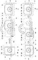
図10(a)は、天地の一方を断裁すべく退避位置P2から断裁位置P1に進出するときの載置テーブル170の動作を示す図である。以下、図10(a)、図10(b)、図11(a)、図11(b)、図12(a)、図12(b)は、載置テーブル170を下方から見た状態を示している。図10(a)の左側に示すように、冊子2を押し付ける押し付け部材であるクランパ180が装置右側に位置しているときの載置テーブル170の周方向位置が、断裁前の初期位置となる。これを、「第1の周方向位置」とする。載置テーブル170は、退避位置P2にあるとき、この第1の周方向位置で断裁対象となる冊子2が載置面170aに載置され、クランパ180によって固定される。   FIG. 10A is a diagram showing the operation of the mounting table 170 when moving from the retracted position P2 to the cutting position P1 to cut one of the top and bottom. Hereinafter, FIG. 10A, FIG. 10B, FIG. 11A, FIG. 11B, FIG. 12A, and FIG. 12B show the mounting table 170 viewed from below. Show. As shown on the left side of FIG. 10A, the circumferential position of the mounting table 170 when the clamper 180 as a pressing member for pressing the booklet 2 is positioned on the right side of the apparatus is the initial position before cutting. This is referred to as a “first circumferential position”. When the placement table 170 is at the retracted position P <b> 2, the booklet 2 to be cut at this first circumferential position is placed on the placement surface 170 a and fixed by the clamper 180.

載置テーブル170に載置された冊子2がクランパ180によって固定されると、電子制御部は、テーブル移動機構18によって載置テーブル170を退避位置P2から断裁位置P1に移動させる。このとき電子制御部は、チェーン222を非噛合位置に保持し、噛合位置に進出させない。このため載置テーブル170は、第1の周方向位置のまま断裁位置P1に進出する。   When the booklet 2 placed on the placement table 170 is fixed by the clamper 180, the electronic control unit causes the table moving mechanism 18 to move the placement table 170 from the retracted position P2 to the cutting position P1. At this time, the electronic control unit holds the chain 222 in the non-meshing position and does not advance the meshing position. For this reason, the mounting table 170 advances to the cutting position P1 while maintaining the first circumferential position.

図10(b)は、天地の一方を断裁後、断裁位置P1から退避位置P2に退避するときの載置テーブル170の動作を示す図である。天2cの断裁が完了すると、電子制御部は、載置テーブル170を断裁位置P1から退避位置P2に退避させる。このときも電子制御部は、チェーン222を非噛合位置に保持し、噛合位置に進出させない。このため載置テーブル170は、第1の周方向位置のまま退避位置P2に退避する。   FIG. 10B is a diagram illustrating the operation of the mounting table 170 when the top and bottom sides are cut and then retracted from the cutting position P1 to the retracted position P2. When the cutting of the top 2c is completed, the electronic control unit retracts the placement table 170 from the cutting position P1 to the retracted position P2. Also at this time, the electronic control unit holds the chain 222 in the non-meshing position and does not advance to the meshing position. For this reason, the mounting table 170 is retracted to the retracted position P2 while maintaining the first circumferential position.

図11(a)は、小口を断裁すべく退避位置P2から断裁位置P1に進出するときの載置テーブル170の動作を示す図である。載置テーブル170が退避位置P2に移動すると、電子制御部は、載置テーブル170を再び断裁位置P1に向けて移動させる。このとき電子制御部は、載置テーブル170を90°回転させるようチェーン222を噛合位置に進出させ、再び非噛合位置に退避させる。このように第1の周方向位置から90°回転した位置を「第2の周方向位置」とする。載置テーブル170は、この第2の周方向位置で断裁位置P1に進出する。これにより、小口2bが刃先移動面L1に達する。   FIG. 11A is a diagram illustrating the operation of the mounting table 170 when moving from the retracted position P2 to the cutting position P1 to cut the fore edge. When the mounting table 170 moves to the retracted position P2, the electronic control unit moves the mounting table 170 again toward the cutting position P1. At this time, the electronic control unit advances the chain 222 to the meshing position so as to rotate the mounting table 170 by 90 °, and retracts it again to the non-meshing position. The position rotated 90 ° from the first circumferential position in this way is referred to as a “second circumferential position”. The placement table 170 advances to the cutting position P1 at the second circumferential position. Thereby, the fore edge 2b reaches the blade edge moving surface L1.

図11(b)は、小口を断裁後、断裁位置P1から退避位置P2に退避するときの載置テーブル170の動作を示す図である。小口2bの断裁が完了すると、電子制御部は、載置テーブル170を断裁位置P1から退避位置P2に再び退避させる。このとき電子制御部は、チェーン222を非噛合位置に保持し、噛合位置に進出させない。このため載置テーブル170は、第2の周方向位置のまま退避位置P2に退避する。   FIG. 11B shows the operation of the mounting table 170 when the fore edge is cut and then retracted from the cutting position P1 to the retracted position P2. When the cutting of the fore edge 2b is completed, the electronic control unit retreats the placement table 170 from the cutting position P1 to the retreat position P2. At this time, the electronic control unit holds the chain 222 in the non-meshing position and does not advance the meshing position. For this reason, the mounting table 170 is retracted to the retracted position P2 while maintaining the second circumferential position.

図12(a)は、天地の他方を断裁すべく退避位置P2から断裁位置P1に進出するときの載置テーブル170の動作を示す図である。載置テーブル170が退避位置P2に移動すると、電子制御部は、載置テーブル170を再び断裁位置P1に向けて移動させる。このとき電子制御部は、載置テーブル170を再び90°回転させるようチェーン222を噛合位置に進出させ、再び非噛合位置に退避させる。このように第2の周方向位置から90°回転した位置を「第3の周方向位置」とする。載置テーブル170は、この第3の周方向位置で断裁位置P1に進出する。これにより、地2dが刃先移動面L1に達する。   FIG. 12A is a diagram illustrating the operation of the mounting table 170 when moving from the retracted position P2 to the cutting position P1 to cut the other of the top and bottom. When the mounting table 170 moves to the retracted position P2, the electronic control unit moves the mounting table 170 again toward the cutting position P1. At this time, the electronic control unit advances the chain 222 to the meshing position so as to rotate the mounting table 170 again by 90 °, and retracts it again to the non-meshing position. The position rotated 90 ° from the second circumferential position in this way is defined as a “third circumferential position”. The mounting table 170 advances to the cutting position P1 at the third circumferential position. Thereby, the ground 2d reaches the cutting edge moving surface L1.

図12(b)は、天地の他方を断裁後、断裁位置P1から退避位置P2に退避するときの載置テーブル170の動作を示す図である。地2dの断裁が完了すると、電子制御部は、載置テーブル170を断裁位置P1から退避位置P2に再び退避させる。このとき電子制御部は、載置テーブル170を逆方向に180°回転させるようチェーン222を噛合位置に進出させ、再び非噛合位置に退避させる。これによって載置テーブル170は、再び第1の周方向位置に戻される。電子制御部は、以下同様の動作を繰り返すことにより、複数の冊子2の各々に断裁処理を施す。   FIG. 12B is a diagram illustrating the operation of the mounting table 170 when the other of the top and bottom is cut and then retracted from the cutting position P1 to the retracted position P2. When the cutting of the ground 2d is completed, the electronic control unit retreats the mounting table 170 from the cutting position P1 to the retreat position P2. At this time, the electronic control unit advances the chain 222 to the meshing position so as to rotate the mounting table 170 by 180 ° in the reverse direction and retracts the chain 222 to the non-meshing position again. As a result, the mounting table 170 is returned to the first circumferential position again. The electronic control unit performs a cutting process on each of the plurality of booklets 2 by repeating the same operation thereafter.

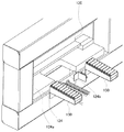
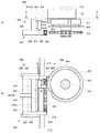
図13は、断裁装置10の右側面図である。図14は、断裁装置10の裏面を示す斜視図である。断裁テーブル124は、載置テーブル170が断裁位置にあるときに、載置テーブル170に載置された用紙束のうち載置テーブル170からはみ出した部分が載置される載置面124aを有する。また、断裁テーブル124は、断裁位置にあるときの載置テーブル170を収容するための凹部124bを有する。凹部124bは、断裁テーブル124の後部中央が切り取られたように形成される。   FIG. 13 is a right side view of the cutting apparatus 10. FIG. 14 is a perspective view showing the back surface of the cutting apparatus 10. The cutting table 124 has a mounting surface 124a on which a portion of the sheet bundle mounted on the mounting table 170 that protrudes from the mounting table 170 is mounted when the mounting table 170 is in the cutting position. Further, the cutting table 124 has a recess 124b for accommodating the mounting table 170 when in the cutting position. The recess 124b is formed such that the rear center of the cutting table 124 is cut off.

ガイド部材であるガイドコロ150は、載置テーブル170の移動中に、載置テーブル170に載置された用紙束のうち載置テーブル170からはみ出した部分を載置面124aに案内する。例えば用紙サイズが大きい用紙束が載置テーブル170に載置された場合、載置テーブル170からはみ出した部分が大きく垂れ下がるおそれがある。このように用紙束が大きく垂れ下がったまま載置テーブル170を退避位置から断裁位置に移動させようとすると、この垂れ下がった部分が断裁テーブル124の後部に突き当たり、用紙束を適切に載置面124a上方に搬送することができない場合が生じ得る。このようにガイドコロ150を設けることにより、このような場合においてもこの冊子のはみ出し部分が断裁テーブルに突き当たる事態を適切に回避することができる。   The guide roller 150, which is a guide member, guides the portion of the sheet bundle placed on the placement table 170 that protrudes from the placement table 170 to the placement surface 124a while the placement table 170 is moving. For example, when a sheet bundle having a large sheet size is placed on the placement table 170, the portion that protrudes from the placement table 170 may drop drastically. In this way, when the placement table 170 is moved from the retracted position to the cutting position while the sheet bundle is drooping greatly, the suspended portion hits the rear part of the cutting table 124, and the sheet bundle is appropriately placed above the placement surface 124a. In some cases, it may not be possible to transport the product. By providing the guide roller 150 in this manner, even in such a case, it is possible to appropriately avoid the situation where the protruding portion of the booklet hits the cutting table.

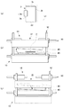
図15(a)は、載置テーブル170が退避位置P2にあるときの第1の実施形態に係る断裁装置10の左側面図である。コイルスプリング280は、載置テーブル170の移動中に載置面124aよりも載置面170aの方が高くなるよう、載置テーブル170を付勢して持ち上げる。   FIG. 15A is a left side view of the cutting apparatus 10 according to the first embodiment when the placement table 170 is at the retracted position P2. The coil spring 280 urges and lifts the mounting table 170 so that the mounting surface 170 a becomes higher than the mounting surface 124 a during the movement of the mounting table 170.

図15(b)は、載置テーブル170が断裁位置P1に進出したときの第1の実施形態に係る断裁装置10の左側面図である。このように載置テーブル170が持ち上げられているため、載置テーブル170に載置された冊子2のうち載置テーブル170からはみ出した部分が垂れ下がった場合においても、その部分が断裁テーブル124に突き当たることを回避することができる。   FIG. 15B is a left side view of the cutting apparatus 10 according to the first embodiment when the mounting table 170 has advanced to the cutting position P1. Since the placement table 170 is lifted in this manner, even when a portion of the booklet 2 placed on the placement table 170 that protrudes from the placement table 170 hangs down, the portion strikes the cutting table 124. You can avoid that.

図15(c)は、載置テーブル170が断裁位置P1で保持されているときに押さえ部材130にて冊子2が押し付けられたときの第1の実施形態に係る断裁装置10の左側面図である。押さえ部材130は、載置テーブル170が断裁位置にあるときに載置面124aに向けて移動させることにより、載置テーブル170に載置された用紙束のうち載置テーブル170からはみ出した部分を断裁テーブル124に押し付ける。このとき押さえ部材130は、断裁テーブル124に用紙束を押し付ける力によって、コイルスプリング280の付勢力に抗して載置テーブル170を下降させる。   FIG. 15C is a left side view of the cutting apparatus 10 according to the first embodiment when the booklet 2 is pressed by the pressing member 130 when the placement table 170 is held at the cutting position P1. is there. The pressing member 130 moves the placement table 170 toward the placement surface 124a when the placement table 170 is in the cutting position, so that a portion of the sheet bundle placed on the placement table 170 is protruded from the placement table 170. Press against the cutting table 124. At this time, the pressing member 130 lowers the placement table 170 against the urging force of the coil spring 280 by the force pressing the sheet bundle against the cutting table 124.

このように押さえ部材130の押し付け力を利用して載置テーブル170を下降させることにより、載置テーブル170を下降させるための駆動源を別途設ける必要がなくなるため、装置の構成を簡素にすることができ、載置テーブル170を持ち上げることによるコストの増加を抑制することができる。   Thus, by lowering the mounting table 170 using the pressing force of the pressing member 130, it is not necessary to separately provide a drive source for lowering the mounting table 170, so that the configuration of the apparatus is simplified. And an increase in cost due to lifting the mounting table 170 can be suppressed.

図16は、押さえ部材130によって押圧される領域を示す図である。図16は、載置テーブル170が断裁位置にあるときの断裁テーブル124を上方から見た状態を示している。このように凹部124bが形成されることにより、載置面124aは、断裁位置にあるときの載置テーブル170の周囲の領域のうち載置テーブル170の移動経路を除く領域内で、断裁位置にあるときの載置テーブル170を囲うように形成される。このように載置面124aを形成することにより、載置テーブル170に載置された用紙束のうち、載置テーブル170からはみ出した部分を広い範囲で載置面124aに載置させることができ、用紙束の湾曲を抑制することができる。   FIG. 16 is a diagram illustrating a region pressed by the pressing member 130. FIG. 16 shows a state in which the cutting table 124 is viewed from above when the mounting table 170 is in the cutting position. By forming the concave portion 124b in this way, the placement surface 124a is at the cutting position within the region around the placement table 170 except the movement path of the placement table 170 at the cutting position. It is formed so as to surround the mounting table 170 at a certain time. By forming the placement surface 124a in this way, a portion of the sheet bundle placed on the placement table 170 that protrudes from the placement table 170 can be placed on the placement surface 124a in a wide range. Thus, the bending of the sheet bundle can be suppressed.

押さえ部材130の押圧面130aは、載置テーブル170と刃先移動面L1との間の領域、載置テーブル170の上方の領域、および載置テーブル170よりも左右方向の領域において、冊子2を載置面124aに押し付けるよう設けられる。これにより、載置テーブル170を下降させつつ、冊子2を適切に固定することができる。   The pressing surface 130 a of the pressing member 130 loads the booklet 2 in a region between the mounting table 170 and the blade edge moving surface L <b> 1, a region above the mounting table 170, and a region in the left-right direction from the mounting table 170. It is provided so as to be pressed against the placement surface 124a. Thereby, the booklet 2 can be appropriately fixed while lowering the placement table 170.

(第2の実施形態)
図17(a)は、載置テーブル170が退避位置P2にあるときの第2の実施形態に係る断裁装置の左側面図である。第2の実施形態に係る断裁装置は、中央押さえユニット300を備える以外は第1の実施形態に係る断裁装置10と同様に構成される。以下、第1の実施形態と同様の個所については同一の符号を付して説明を省略する。
(Second Embodiment)
FIG. 17A is a left side view of the cutting apparatus according to the second embodiment when the placement table 170 is at the retracted position P2. The cutting apparatus according to the second embodiment is configured in the same manner as the cutting apparatus 10 according to the first embodiment, except that the center pressing unit 300 is provided. Hereinafter, the same parts as those in the first embodiment are denoted by the same reference numerals and description thereof is omitted.

中央押さえユニット300は、支持部材302、押さえ部材304、およびコイルスプリング306を備える。支持部材302はL字状の部材であり、後部が下方に突出するよう押さえ部材130の裏面に一端が固定される。支持部材302の後部の下端には、コイルスプリング306を介して押さえ部材304が取り付けられる。押さえ部材304は直方体状に形成されており、下面に冊子2を下方に押し付ける押圧面304aを有する。   The central pressing unit 300 includes a support member 302, a pressing member 304, and a coil spring 306. The support member 302 is an L-shaped member, and one end is fixed to the back surface of the pressing member 130 so that the rear portion protrudes downward. A pressing member 304 is attached to the lower end of the rear portion of the support member 302 via a coil spring 306. The pressing member 304 is formed in a rectangular parallelepiped shape, and has a pressing surface 304 a that presses the booklet 2 downward on the lower surface.

押さえ部材304は、押圧面304aが押さえ部材130の押圧面130aよりも装置後方に位置するよう配置される。また押さえ部材304は、冊子2を押圧していない状態では押圧面304aが押さえ部材130の押圧面130aよりも下方に位置するようコイルスプリング306を介して支持部材302によって懸架される。   The pressing member 304 is disposed such that the pressing surface 304 a is positioned behind the apparatus with respect to the pressing surface 130 a of the pressing member 130. Further, the pressing member 304 is suspended by the support member 302 via the coil spring 306 so that the pressing surface 304 a is positioned below the pressing surface 130 a of the pressing member 130 when the booklet 2 is not pressed.

図17(b)は、載置テーブル170が断裁位置P1に進出したときの第2の実施形態に係る断裁装置の左側面図である。このとき、押さえ部材304は、押圧面304aの中心がピストン274の中心、すなわち載置テーブル170の回転軸と重なるよう位置する。   FIG. 17B is a left side view of the cutting apparatus according to the second embodiment when the placement table 170 has advanced to the cutting position P1. At this time, the pressing member 304 is positioned such that the center of the pressing surface 304 a overlaps the center of the piston 274, that is, the rotation axis of the mounting table 170.

図17(c)は、載置テーブル170が断裁位置P1で保持されているときに押さえ部材130にて冊子2が押し付けられたときの第2の実施形態に係る断裁装置の左側面図である。図18は、押さえ部材130およびもう一方の押さえ部材304によって押圧される領域を示す図である。押さえ部材130が下降すると、最初に押さえ部材304の押圧面304aによって冊子2が下方に押し付けられる。次にコイルスプリング306が収縮して押さえ部材304と押さえ部材130の双方により冊子2が下方に押し付けられる。最終的には、冊子2は断裁テーブル124と押さえ部材130により把持される。   FIG. 17C is a left side view of the cutting apparatus according to the second embodiment when the booklet 2 is pressed by the pressing member 130 when the placement table 170 is held at the cutting position P1. . FIG. 18 is a diagram illustrating a region pressed by the pressing member 130 and the other pressing member 304. When the pressing member 130 is lowered, the booklet 2 is first pressed downward by the pressing surface 304 a of the pressing member 304. Next, the coil spring 306 contracts and the booklet 2 is pressed downward by both the pressing member 304 and the pressing member 130. Eventually, the booklet 2 is gripped by the cutting table 124 and the pressing member 130.

このように押さえ部材130が載置テーブル170に載置された冊子2のうち載置テーブル170からはみ出した部分を断裁テーブル124に押し付けるときに、押さえ部材304は、載置テーブル170に載置された冊子2のうち載置テーブル170の回転中心を含む部分を下方に押し付けることにより載置テーブル170を下降させる。押さえ部材304は、載置テーブル170の回転中心、すなわちピストン274の中心を下方に押し付けるため、ピストン274とシリンダ276との間のかじりの発生を抑制することができ、冊子2を円滑に下降させることができる。   In this way, when the pressing member 130 presses the portion of the booklet 2 placed on the placement table 170 that protrudes from the placement table 170 against the cutting table 124, the pressure member 304 is placed on the placement table 170. The placement table 170 is lowered by pressing downward the portion of the booklet 2 that includes the rotation center of the placement table 170. Since the pressing member 304 presses the rotation center of the mounting table 170, that is, the center of the piston 274 downward, it is possible to suppress the occurrence of galling between the piston 274 and the cylinder 276, and to smoothly lower the booklet 2. be able to.

なお、支持部材302およびコイルスプリング306が省略され、押さえ部材304が押さえ部材130と一体的に形成されていてもよい。このとき、押圧面304aと押圧面130aが同一平面上に位置するよう押さえ部材304および押さえ部材130が構成されてもよい。これによっても載置テーブル170を円滑に下降させることができる。   Note that the support member 302 and the coil spring 306 may be omitted, and the pressing member 304 may be formed integrally with the pressing member 130. At this time, the pressing member 304 and the pressing member 130 may be configured so that the pressing surface 304a and the pressing surface 130a are positioned on the same plane. Also by this, the mounting table 170 can be smoothly lowered.

(第3の実施形態)
図19は、第3の実施形態に係るイニシャル位置検知機構400の構成を示す図である。図19は、テーブルユニット16およびテーブル移動機構18を図4の視点Sから見た状態を示している。以下、上述の実施形態と同様の個所については同一の符号を付して説明を省略する。
(Third embodiment)
FIG. 19 is a diagram illustrating a configuration of an initial position detection mechanism 400 according to the third embodiment. FIG. 19 shows a state where the table unit 16 and the table moving mechanism 18 are viewed from the viewpoint S of FIG. Hereinafter, the same parts as those in the above-described embodiment are denoted by the same reference numerals and description thereof is omitted.

例えば断裁位置と退避位置との間で、電源がオフにされるなど何かしらの原因で載置テーブル170の周方向位置を装置が把握することが困難となる事態が生じ得る。このような場合、載置テーブル170の位置を再び適切に把握する必要がある。このため、第3の実施形態に係る断裁装置には、イニシャル位置検知機構400が設けられている。イニシャル位置検知機構400が設けられた以外は、第3の実施形態に係る断裁装置の構成は、上述の実施形態にいずれかに係る断裁装置と同様である。   For example, it may be difficult for the device to grasp the circumferential position of the mounting table 170 between the cutting position and the retracted position for some reason, such as when the power is turned off. In such a case, it is necessary to properly grasp the position of the mounting table 170 again. For this reason, the cutting apparatus according to the third embodiment is provided with an initial position detection mechanism 400. Except for the provision of the initial position detection mechanism 400, the configuration of the cutting apparatus according to the third embodiment is the same as the cutting apparatus according to any of the above-described embodiments.

イニシャル位置検知機構400は、被検知部材404、光センサ406、被検知部材410、および光センサ412を有する。被検知部材404は、載置テーブル170とともに回転するよう載置テーブル170に対して固定されている。光センサ406は、被検知部材404を検知することにより載置テーブル170の回転方向の位置(周方向位置)を検知する。   The initial position detection mechanism 400 includes a detected member 404, an optical sensor 406, a detected member 410, and an optical sensor 412. The detected member 404 is fixed to the mounting table 170 so as to rotate together with the mounting table 170. The optical sensor 406 detects the position (circumferential position) in the rotation direction of the mounting table 170 by detecting the detected member 404.

具体的には、被検知部材404は、載置テーブル170の回転中心に対し径外向きに突出する突出部404aを有する。光センサ406は、発光素子と受光素子を含み、一方が装置前方、他方が装置後方に配置されている。光センサ406は、光の遮蔽を検知すべき対象個所である検知ラインXが載置テーブル170の移動方向と平行になるように配置されている。被検知部材404は、チェーン222を進出させてスプロケット220に噛合させたときの載置テーブル170の回転に伴い、突出部404aが検知ラインXに進出および退避するよう設けられる。光センサ406は、突出部404aが検知ラインXに進出したときに検知ラインXを通過する光が遮断され、突出部404aを検知する。光センサ406は、被検知部材404が回転して検知ラインXに到達した突出部404aを検知することにより、載置テーブル170の周方向位置を検知する。   Specifically, the detected member 404 has a protruding portion 404 a that protrudes radially outward with respect to the rotation center of the mounting table 170. The optical sensor 406 includes a light emitting element and a light receiving element, and one is arranged in front of the apparatus and the other is arranged in the rear of the apparatus. The optical sensor 406 is arranged so that the detection line X, which is a target portion where light shielding should be detected, is parallel to the moving direction of the mounting table 170. The detected member 404 is provided such that the protruding portion 404a advances and retreats to the detection line X with the rotation of the mounting table 170 when the chain 222 is advanced and meshed with the sprocket 220. The optical sensor 406 detects the protrusion 404a by blocking light passing through the detection line X when the protrusion 404a advances into the detection line X. The optical sensor 406 detects the circumferential position of the mounting table 170 by detecting the protruding portion 404a that the detected member 404 has rotated and reaches the detection line X.

例えば載置テーブル170に周方向位置を検知するセンサを設けると、載置テーブル170の移動に伴うセンサケーブルの移動スペースを確保する必要がある。このため、イニシャル位置検知機構400では、載置テーブル170が搭載されたテーブルユニット16には被検知部材404だけが設けられ、光センサ406はフレーム200に取り付けられている。このように載置テーブル170の周方向位置を検知するセンサのテーブルユニット16への搭載を回避することで、センサに接続するためのケーブルが載置テーブル170とともに移動することなどを考慮する必要がなくなる。このため、センサに接続するケーブルが占有するスペースを抑制でき、装置の小型化または低コスト化を実現することができる。   For example, when a sensor for detecting a circumferential position is provided on the mounting table 170, it is necessary to secure a movement space for the sensor cable accompanying the movement of the mounting table 170. For this reason, in the initial position detection mechanism 400, only the detected member 404 is provided on the table unit 16 on which the placement table 170 is mounted, and the optical sensor 406 is attached to the frame 200. Thus, it is necessary to consider that the cable for connecting to the sensor moves together with the mounting table 170 by avoiding mounting the sensor for detecting the circumferential position of the mounting table 170 on the table unit 16. Disappear. For this reason, the space which the cable connected to a sensor occupies can be suppressed, and size reduction or cost reduction of an apparatus can be realized.

光センサ412は、フレーム200に固定された支持部材に取り付けられる。被検知部材410は、テーブルユニット16の支持ブラケット172に取り付けられる。光センサ412は、載置テーブル170がある位置に移動したときに被検知部材410を検知するよう設けられる。以下、光センサ412によって被検知部材410が検知されたときの載置テーブル170の位置を「原点」という。したがって、光センサ412は、載置テーブル170の原点位置を検知する原点センサとして機能する。   The optical sensor 412 is attached to a support member fixed to the frame 200. The detected member 410 is attached to the support bracket 172 of the table unit 16. The optical sensor 412 is provided so as to detect the detected member 410 when the placement table 170 moves to a certain position. Hereinafter, the position of the mounting table 170 when the detected member 410 is detected by the optical sensor 412 is referred to as “origin”. Therefore, the optical sensor 412 functions as an origin sensor that detects the origin position of the mounting table 170.

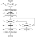
図20は、第3の実施形態に係るイニシャル位置検知機構400によるイニシャライズ処理の手順を示すフローチャートである。本フローチャートにおける処理は、断裁装置10においてスタートボタンがユーザに押されて断裁処理が開始してから、断裁処理が中止または中断するまで処理時間毎に繰り返し実行される。   FIG. 20 is a flowchart showing a procedure of initialization processing by the initial position detection mechanism 400 according to the third embodiment. The processing in this flowchart is repeatedly executed every processing time after the start button is pressed by the user in the cutting device 10 and the cutting processing is started until the cutting processing is stopped or interrupted.

電子制御部は、イニシャライズ処理が必要か否かを判定する(S10)。イニシャライズ処理が必要な場合とは、例えば、断裁処理中に装置のドアがユーザに開けられて電子制御部が断裁処理を中断し、その後ドアが閉められて電子制御部が断裁処理を再開させるときや、断裁処理中に停電やユーザによって電源がオフにされ、再び断裁装置10に電源が投入された場合などが該当する。なお、イニシャライズ処理が必要な場合がこれらの場合に限られないことは勿論であり、断裁処理中に載置テーブル170の周方向位置を電子制御部が認識不能となる他の場合もイニシャライズ処理が必要となる。イニシャライズ処理が必要でない場合(S10のN)、本フローチャートにおける処理を終了する。   The electronic control unit determines whether or not an initialization process is necessary (S10). The case where the initialization process is necessary is, for example, when the device door is opened by the user during the cutting process, the electronic control unit interrupts the cutting process, and then the door is closed and the electronic control unit resumes the cutting process. In addition, a case where a power failure or a user power is turned off by the user during the cutting process and the power is turned on again is applicable. Of course, the case where the initialization process is necessary is not limited to these cases, and the initialization process is also performed in other cases where the electronic control unit cannot recognize the circumferential position of the mounting table 170 during the cutting process. Necessary. If the initialization process is not necessary (N in S10), the process in this flowchart is terminated.

イニシャライズ処理が必要な場合(S10のY)、電子制御部は、載置テーブル170を原点に移動させる(S12)。載置テーブル170が原点に移動すると、電子制御部は、チェーン222が進出してスプロケット220に噛合開始する噛合開始位置に向けて、断裁位置P1に向かう方向(以下「進出方向」という)に載置テーブル170を移動させる(S14)。   When the initialization process is necessary (Y in S10), the electronic control unit moves the placement table 170 to the origin (S12). When the placement table 170 moves to the origin, the electronic control unit places the chain 222 in the direction toward the cutting position P1 (hereinafter referred to as “advance direction”) toward the engagement start position where the chain 222 starts to engage with the sprocket 220. The table 170 is moved (S14).

噛合開始位置まで載置テーブル170が移動されると、電子制御部は、チェーン222を進出させてスプロケット220に噛合させる(S16)。このとき、載置テーブル170は引き続き進出方向に移動するため、載置テーブル170および被検知部材404の回転が開始する。   When the mounting table 170 is moved to the meshing start position, the electronic control unit advances the chain 222 to mesh with the sprocket 220 (S16). At this time, since the mounting table 170 continues to move in the advance direction, the mounting table 170 and the detected member 404 start to rotate.

電子制御部は、光センサ406によって突出部404aが検知されたか否かを判定する(S18)。突出部404aが検知されない場合(S18のN)、電子制御部は、噛合開始位置からの載置テーブル170の回転角度が90度に達したか否かを判定し(S26)、達していない場合(S26のN)、S18の判定に戻る。こうして電子制御部は、載置テーブル170が90度回転している間、すなわち載置テーブル170が噛合開始位置から、チェーン222がスプロケット220から退避して載置テーブル170の回転を停止させる噛合終了位置まで移動する間、所定時間毎にS18の判定を繰り返す。第3の実施形態では、この1工程の間に載置テーブル170が90度回転することから、多くても4工程の間に突出部404aが光センサ406に検知されることになる。   The electronic control unit determines whether the protruding portion 404a is detected by the optical sensor 406 (S18). When the protrusion 404a is not detected (N in S18), the electronic control unit determines whether or not the rotation angle of the mounting table 170 from the meshing start position has reached 90 degrees (S26). (N of S26), it returns to the determination of S18. In this way, the electronic control unit finishes meshing while the placement table 170 is rotated 90 degrees, that is, the placement table 170 is retracted from the sprocket 220 and the rotation of the placement table 170 is stopped by retracting the chain 222 from the sprocket 220. While moving to the position, the determination of S18 is repeated every predetermined time. In the third embodiment, since the mounting table 170 rotates 90 degrees during this one step, the protrusion 404a is detected by the optical sensor 406 during at most four steps.

載置テーブル170の回転角度が90度に達した場合(S26のY)、電子制御部は、載置テーブル170の進出方向への移動を停止させた直後にチェーン222を退避させて載置テーブル170の回転を停止させ(S28)、S12に戻る。すなわち、載置テーブル170を再び噛合開始位置に戻し、チェーン222を進出させてスプロケット220に噛合させてから載置テーブル170を進出方向に移動させ、噛合終了位置に到達するまでの間、載置テーブル170を回転させながら光センサ406によって突出部404aが検知されたか否かを判定する。電子制御部は、光センサ406によって突出部404aが検知されるまでこの工程を繰り返す。   When the rotation angle of the mounting table 170 reaches 90 degrees (Y in S26), the electronic control unit retracts the chain 222 immediately after stopping the movement of the mounting table 170 in the advance direction. The rotation of 170 is stopped (S28), and the process returns to S12. That is, the mounting table 170 is returned to the meshing start position, the chain 222 is advanced and meshed with the sprocket 220, and the mounting table 170 is moved in the advanced direction until the meshing end position is reached. It is determined whether or not the protrusion 404a is detected by the optical sensor 406 while rotating the table 170. The electronic control unit repeats this process until the protruding portion 404a is detected by the optical sensor 406.

突出部404aが検知された場合(S18のY)、電子制御部は、突出部404aの検知後も引き続き載置テーブル170を進出方向に移動させ、第1の周方向位置に位置するよう載置テーブル170の角度を微調整する(S20)。載置テーブル170が第1の周方向位置に位置すると、電子制御部は、チェーン222を退避させ(S22)、載置テーブル170を退避方向に移動させて原点に移動させる(S24)。   When the protruding portion 404a is detected (Y in S18), the electronic control unit continues to move the mounting table 170 in the advance direction even after the detection of the protruding portion 404a, and is placed so as to be positioned at the first circumferential position. The angle of the table 170 is finely adjusted (S20). When the mounting table 170 is located at the first circumferential position, the electronic control unit retracts the chain 222 (S22), moves the mounting table 170 in the retracting direction, and moves it to the origin (S24).

図21は、第3の実施形態に係るイニシャライズ処理を実行したときの被検知部材404の動きを模式的に示した物である。図21は、図19と同様に被検知部材404を下方から見た状態を示している。図21では、原点を「P10」、噛合開始位置を「P11」、噛合終了位置を「P12」、光センサ406による検知ラインを「X」として示している。   FIG. 21 schematically shows the movement of the detected member 404 when the initialization process according to the third embodiment is executed. FIG. 21 shows a state in which the detected member 404 is viewed from below as in FIG. In FIG. 21, the origin is indicated as “P10”, the engagement start position as “P11”, the engagement end position as “P12”, and the detection line by the optical sensor 406 as “X”.

イニシャライズ処理を要すると判定した場合、電子制御部は、(a)に示すように、載置テーブル170を(すなわち被検知部材404を)原点P10に移動させてから進出方向に被検知部材404を移動させる。被検知部材404が噛合開始位置P11まで達すると、電子制御部は、チェーン222を進出させてスプロケット220に噛合させる。電子制御部は、(b)に示すように被検知部材404を引き続き進出方向に移動させ、これにより被検知部材404の回転が開始する。   If it is determined that the initialization process is required, the electronic control unit moves the placement table 170 (that is, the detected member 404) to the origin P10 and moves the detected member 404 in the advance direction as shown in FIG. Move. When the detected member 404 reaches the meshing start position P11, the electronic control unit advances the chain 222 to mesh with the sprocket 220. The electronic control unit continues to move the detected member 404 in the advancing direction as shown in (b), whereby the detected member 404 starts to rotate.

電子制御部は、被検知部材404が回転しながら噛合開始位置P11から噛合終了位置P12へと移動する間に、光センサ406によって突出部404aが検知されたか否かを監視する。図21に示す例では、(c)に示すように、被検知部材404が噛合開始位置P11から噛合終了位置P12へと1回目に移動する間では、突出部404aは検知ラインXに到達しない。このため電子制御部は、噛合終了位置P12において被検知部材404の移動を停止させると共に、チェーン222を退避させスプロケット220との噛合を解除させ、(c)に示すように今度は被検知部材404を退避方向に移動させる。このとき被検知部材404は回転することなく退避方向に移動する。   The electronic control unit monitors whether the protruding portion 404a is detected by the optical sensor 406 while the detected member 404 moves from the meshing start position P11 to the meshing end position P12 while rotating. In the example shown in FIG. 21, as shown in (c), the protrusion 404 a does not reach the detection line X while the detected member 404 moves from the engagement start position P11 to the engagement end position P12 for the first time. For this reason, the electronic control unit stops the movement of the detected member 404 at the engagement end position P12 and also retracts the chain 222 to release the engagement with the sprocket 220. This time, as shown in FIG. Is moved in the retracting direction. At this time, the detected member 404 moves in the retracting direction without rotating.

被検知部材404が噛合開始位置P11に到達すると、電子制御部は被検知部材404の退避方向への移動を停止させ、再びチェーン222を進出させてスプロケット220に噛合させて、(d)に示すように再び被検知部材404を進出方向に移動させる。これにより、被検知部材404は、再び回転しながら進出方向に移動する。   When the detected member 404 reaches the engagement start position P11, the electronic control unit stops the movement of the detected member 404 in the retracting direction, and advances the chain 222 again to engage the sprocket 220, as shown in FIG. Then, the detected member 404 is moved again in the advance direction. As a result, the detected member 404 moves in the advance direction while rotating again.

図21に示す例では、被検知部材404を噛合開始位置P11と噛合終了位置P12との間で移動させる2回目の工程において、突出部404aが検知ラインXに達し、突出部404aが光センサ406によって検知される。このときの被検知部材404の位置を検知位置P13とする。   In the example shown in FIG. 21, in the second step of moving the detected member 404 between the engagement start position P11 and the engagement end position P12, the protrusion 404a reaches the detection line X, and the protrusion 404a is the optical sensor 406. Detected by. The position of the detected member 404 at this time is set as a detection position P13.

(e)に示すように、被検知部材404が検知位置P13にあるときには、突出部404aは図21における上方向、すなわち断裁装置10における装置左方向に向いていない。第3の実施形態では、突出部404aが装置左方向に向いたときに載置テーブル170が第1の周方向位置に位置するよう設けられる。このため電子制御部は、(e)に示すように、検知位置P13から被検知部材404をさらに進出方向に移動させて被検知部材404を回転させ、載置テーブル170の周方向位置を微調整する。   As shown to (e), when the to-be-detected member 404 exists in the detection position P13, the protrusion part 404a does not face the upper direction in FIG. 21, ie, the apparatus left direction in the cutting device 10. FIG. In the third embodiment, the mounting table 170 is provided so as to be positioned at the first circumferential position when the projecting portion 404a faces in the left direction of the apparatus. Therefore, the electronic control unit finely adjusts the circumferential position of the mounting table 170 by rotating the detected member 404 by moving the detected member 404 further from the detection position P13 in the advance direction, as shown in (e). To do.

載置テーブル170を進出方向および退避方向に移動させるためのアクチュエータであるモータ204は、ステッピングモータによって構成されている。モータ204は、電子制御部から与えられるステップ信号のステップ数に相当する角度だけボールネジ202を回転させて載置テーブル170を移動させる。一方、電子制御部は、モータ204に取り付けられたエンコーダから発信される回転量信号を受信することにより、モータ204の実際の回転角度を把握することができ、さらに被検知部材404の回転角度を把握することができる。   The motor 204, which is an actuator for moving the mounting table 170 in the advance direction and the retracting direction, is configured by a stepping motor. The motor 204 moves the mounting table 170 by rotating the ball screw 202 by an angle corresponding to the number of steps of the step signal given from the electronic control unit. On the other hand, the electronic control unit can grasp the actual rotation angle of the motor 204 by receiving the rotation amount signal transmitted from the encoder attached to the motor 204, and further determine the rotation angle of the detected member 404. I can grasp it.

なお、モータ204は、サーボモータによって構成されてもよい。この場合、電子制御部は、モータ204から発信されるFG(Frequency Generator)信号を受信することにより、モータ204の実際の回転角度を把握することができ、さらに被検知部材404の回転角度を把握することができる。   The motor 204 may be constituted by a servo motor. In this case, the electronic control unit can grasp the actual rotation angle of the motor 204 by receiving an FG (Frequency Generator) signal transmitted from the motor 204, and further grasp the rotation angle of the detected member 404. can do.

電子制御部は、突出部404aが光センサ406によって検知されたときから突出部404aが装置左方向に向くまで、すなわち載置テーブル170が第1の周方向位置に位置するまでに受信すべきモータ204の回転量信号の基準値を保持している。電子制御部は、突出部404aが光センサ406によって検知されてからモータ204の回転量信号を用いて被検知部材404の回転角度を監視し、保持している基準値に回転量信号が到達したときに、載置テーブル170が第1の周方向位置に位置したと判定して被検知部材404の進出方向への移動を停止させてその回転を停止させる。こうして(f)に示すように、突出部404aを装置左方向(図21における上方向)に向かせて、載置テーブル170を第1の周方向位置に位置させることができる。   The electronic control unit is a motor that should be received from when the protruding portion 404a is detected by the optical sensor 406 until the protruding portion 404a faces in the left direction of the apparatus, that is, until the mounting table 170 is positioned at the first circumferential position. The reference value of the rotation amount signal 204 is held. The electronic control unit monitors the rotation angle of the detected member 404 using the rotation amount signal of the motor 204 after the protrusion 404a is detected by the optical sensor 406, and the rotation amount signal reaches the held reference value. When it is determined that the placement table 170 is located at the first circumferential position, the movement of the detected member 404 in the advance direction is stopped and the rotation is stopped. Thus, as shown in (f), the mounting table 170 can be positioned at the first circumferential position with the protruding portion 404a facing the device leftward (upward in FIG. 21).

なお、電子制御部は、突出部404aが光センサ406によって検知されたときから突出部404aが装置左方向に向くまで、すなわち載置テーブル170が第1の周方向位置に位置するまでにモータ204に与えるべきステップ数の基準値を保持していてもよい。電子制御部は、突出部404aが光センサ406によって検知されてからモータ204に与えたステップ数をカウントして被検知部材404の回転角度を監視し、保持している基準値にステップ数が到達したときに、載置テーブル170が第1の周方向位置に位置したとして被検知部材404の進出方向への移動を停止させてその回転を停止させてもよい。これによっても載置テーブル170を第1の周方向位置に適切に配置させることができる。   It should be noted that the electronic control unit determines that the motor 204 is in a state from when the protruding portion 404a is detected by the optical sensor 406 until the protruding portion 404a faces in the left direction of the apparatus, that is, until the mounting table 170 is positioned at the first circumferential position. May hold a reference value of the number of steps to be given to. The electronic control unit counts the number of steps applied to the motor 204 after the protrusion 404a is detected by the optical sensor 406, monitors the rotation angle of the detected member 404, and the number of steps reaches the held reference value. Then, assuming that the mounting table 170 is located at the first circumferential position, the movement of the detected member 404 in the advance direction may be stopped to stop its rotation. Also by this, the mounting table 170 can be appropriately arranged at the first circumferential position.

最後に電子制御部は、チェーン222をスプロケット220から退避させた後、被検知部材404を再び退避方向に移動させ、(g)に示すように原点P10にて停止させる。この後、電子制御部は、イニシャライズ処理を実行するために中断していた断裁処理を再開するなど、所定の処理を実行する。   Finally, after the chain 222 is retracted from the sprocket 220, the electronic control unit moves the detected member 404 again in the retracting direction and stops at the origin P10 as shown in (g). Thereafter, the electronic control unit executes a predetermined process such as resuming the cutting process that has been interrupted in order to execute the initialization process.

(第4の実施形態)
図22(a)および図22(b)は、第4の実施形態に係るイニシャル位置検知機構500の構成を示す図である。図22(a)は、スプロケット220および噛合切替機構224周辺を、載置テーブル170の退避方向に向いて見た状態を示しており、図22(b)は、図22(a)のT−T断面図である。
(Fourth embodiment)
FIG. 22A and FIG. 22B are diagrams showing a configuration of an initial position detection mechanism 500 according to the fourth embodiment. FIG. 22A shows a state in which the sprocket 220 and the mesh switching mechanism 224 and the periphery thereof are viewed in the retracting direction of the mounting table 170, and FIG. 22B shows a state T- in FIG. It is T sectional drawing.

イニシャル位置検知機構500は、進退ユニット502、スリット板504、およびテーブル側ピン506を備える。進退ユニット502は、噛合切替機構224に設けられている。スリット板504は円盤状に形成され、スプロケット220と位置決めロータ252との間にそれらと同軸に配置される。スリット板504は、載置テーブル170の回転中心に対し径内向きに凹む凹部504aを有する。テーブル側ピン506は、支持ブラケット172の下面から下方に突出するように支持ブラケット172に固定される。したがってテーブル側ピン506は、載置テーブル170、スプロケット220、およびスリット板504とともに断裁位置P1と退避位置P2との間を移動する。   The initial position detection mechanism 500 includes an advance / retreat unit 502, a slit plate 504, and a table side pin 506. The advance / retreat unit 502 is provided in the mesh switching mechanism 224. The slit plate 504 is formed in a disk shape, and is disposed coaxially between the sprocket 220 and the positioning rotor 252. The slit plate 504 has a recess 504 a that is recessed radially inward with respect to the rotation center of the mounting table 170. The table side pin 506 is fixed to the support bracket 172 so as to protrude downward from the lower surface of the support bracket 172. Therefore, the table side pin 506 moves between the cutting position P1 and the retracted position P2 together with the mounting table 170, the sprocket 220, and the slit plate 504.

進退ユニット502は、センサユニット510、ガイド512、およびコイルスプリング514を有する。ガイド512は、チェーン222よりも上方において載置テーブル170の移動方向と平行に延在するようロッド228に取り付けられる。ガイド512は、載置テーブル170の移動方向と平行に移動可能にセンサユニット510を支持する。   The advance / retreat unit 502 includes a sensor unit 510, a guide 512, and a coil spring 514. The guide 512 is attached to the rod 228 so as to extend in parallel with the moving direction of the mounting table 170 above the chain 222. The guide 512 supports the sensor unit 510 so as to be movable in parallel with the moving direction of the mounting table 170.

センサユニット510は、センサベース520、センサ側ピン522、および光センサ524を有する。センサベース520は、ガイド512によって支持される部分となっている。センサ側ピン522は、センサベース520からテーブル側ピン506の移動領域に向かう方向に突出するようセンサベース520に固定される。センサ側ピン522は、チェーン222が退避位置にあるときには、テーブル側ピン506の移動領域から退避し、噛合切替機構224によってチェーン222が進出位置に進出したときにテーブル側ピン506の移動領域に進出するよう設けられる。   The sensor unit 510 includes a sensor base 520, a sensor side pin 522, and an optical sensor 524. The sensor base 520 is a portion supported by the guide 512. The sensor side pin 522 is fixed to the sensor base 520 so as to protrude in a direction from the sensor base 520 toward the moving region of the table side pin 506. When the chain 222 is in the retracted position, the sensor-side pin 522 is retracted from the moving area of the table-side pin 506, and when the chain 222 is advanced to the advanced position by the mesh switching mechanism 224, the sensor-side pin 522 is advanced to the moving area of the table-side pin 506. To be provided.

光センサ524は、センサベース520よりもスリット板504の移動領域に向かって突出するようセンサベース520に固定される。光センサ524は、チェーン222が退避する方向に凹む凹部を有し、発光素子と受光素子とがこの凹部の上方および下方の各々にそれぞれ配置され構成されている。したがって、光センサ524は、この凹部の内部が検知範囲となる。光センサ524は、チェーン222が退避位置にあるときには、スリット板504の移動領域が検知範囲外となり、噛合切替機構224によってチェーン222が進出位置に進出したときにスリット板504の移動領域が検知範囲内となるよう設けられる。スリット板504の凹部504aがこの光センサ524によって検知されることによって、電子制御部は載置テーブル170の周方向位置を把握する。このためスリット板504は、光センサ524によって検知される被検知部材として機能する。   The optical sensor 524 is fixed to the sensor base 520 so as to protrude from the sensor base 520 toward the moving region of the slit plate 504. The optical sensor 524 has a recess that is recessed in the direction in which the chain 222 is retracted, and a light emitting element and a light receiving element are respectively disposed above and below the recess. Therefore, in the optical sensor 524, the inside of this recess is the detection range. In the optical sensor 524, when the chain 222 is in the retracted position, the moving area of the slit plate 504 is out of the detection range, and when the chain 222 is advanced to the advanced position by the mesh switching mechanism 224, the moving area of the slit plate 504 is detected. It is provided to be inside. When the concave portion 504 a of the slit plate 504 is detected by the optical sensor 524, the electronic control unit grasps the circumferential position of the mounting table 170. Therefore, the slit plate 504 functions as a member to be detected that is detected by the optical sensor 524.

コイルスプリング514は、センサベース520の装置後方側の側面と、フレーム200に固定された支持部材とに両端の各々が取り付けられる。コイルスプリング514は、センサユニット510を装置後方、すなわち載置テーブル170の退避方向に付勢する付勢部材として機能する。   Each end of the coil spring 514 is attached to the side surface of the sensor base 520 on the rear side of the device and a support member fixed to the frame 200. The coil spring 514 functions as a biasing member that biases the sensor unit 510 in the rear direction of the apparatus, that is, in the retracting direction of the mounting table 170.

図22(a)および(b)は、チェーン222が退避位置にあるときのイニシャル位置検知機構500の状態を示している。このときセンサ側ピン522はテーブル側ピン506の移動領域から退避し、光センサ524は、スリット板504の移動領域が検知範囲外となっている。   22A and 22B show the state of the initial position detection mechanism 500 when the chain 222 is in the retracted position. At this time, the sensor-side pin 522 is retracted from the movement area of the table-side pin 506, and the movement area of the slit plate 504 is out of the detection range of the optical sensor 524.

図23(a)および図23(b)は、チェーン222を進出位置に進出させたときのイニシャル位置検知機構500の状態を示す図である。載置テーブル170が噛合開始位置P11まで進出方向に移動すると、噛合切替機構224によってチェーン222が進出位置に進出される。このとき、センサ側ピン522はテーブル側ピン506の移動領域に進出し、スリット板504の移動領域が光センサ524の検知範囲内となる。   FIG. 23A and FIG. 23B are views showing the state of the initial position detection mechanism 500 when the chain 222 is advanced to the advanced position. When the placement table 170 moves in the advance direction to the mesh start position P11, the chain 222 is advanced to the advance position by the mesh switching mechanism 224. At this time, the sensor side pin 522 advances into the moving area of the table side pin 506, and the moving area of the slit plate 504 is within the detection range of the optical sensor 524.

テーブル側ピン506は、チェーン222が進出位置に進出したときには、センサ側ピン522に当接しないようセンサ側ピン522よりもわずかに載置テーブル170の退避方向に位置するよう配置されている。チェーン222が進出位置に進出後、さらに載置テーブル170が進出方向に移動することによって、テーブル側ピン506がセンサ側ピン522に当接し、センサユニット510を進出方向に押し進め始める。こうして光センサ406は、載置テーブル170とともに進出方向に移動する。   The table-side pin 506 is arranged so as to be positioned slightly in the retracting direction of the placement table 170 so as not to contact the sensor-side pin 522 when the chain 222 has advanced to the advance position. After the chain 222 has advanced to the advanced position, the mounting table 170 further moves in the advanced direction, whereby the table-side pin 506 contacts the sensor-side pin 522 and starts to push the sensor unit 510 in the advanced direction. Thus, the optical sensor 406 moves in the advance direction together with the mounting table 170.

このとき、チェーン222はスプロケット220に噛合しているため、載置テーブル170の進出方向への移動に伴い、スプロケット220およびスリット板504が回転する。光センサ406は、載置テーブル170とともに進出方向に移動しながら、回転するスリット板504の凹部504aを検知することにより、載置テーブル170の周方向位置を検知する。図23(a)および図23(b)は、チェーン222が進出位置に進出した後、テーブル側ピン506がセンサ側ピン522に当接した直後の状態を示している。   At this time, since the chain 222 is meshed with the sprocket 220, the sprocket 220 and the slit plate 504 rotate as the mounting table 170 moves in the advance direction. The optical sensor 406 detects the circumferential position of the mounting table 170 by detecting the concave portion 504a of the rotating slit plate 504 while moving in the advance direction together with the mounting table 170. FIG. 23A and FIG. 23B show a state immediately after the table 222 has come into contact with the sensor-side pin 522 after the chain 222 has advanced to the advance position.

図24(a)は、光センサ524によってスリット板504の凹部504aが検知されたときのイニシャル位置検知機構500の状態を示す図であり、図24(b)は、図24(a)の状態からチェーン222を退避位置まで退避させたときのイニシャル位置検知機構500の状態を示す図である。   FIG. 24A is a diagram illustrating a state of the initial position detection mechanism 500 when the concave portion 504a of the slit plate 504 is detected by the optical sensor 524, and FIG. 24B is a state of FIG. FIG. 6 is a diagram illustrating a state of the initial position detection mechanism 500 when the chain 222 is retracted from the position to the retracted position.

スリット板504の回転開始から90度回転するまでにスリット板504の凹部504aが装置左側、すなわち図24(a)における左側まで達する場合、光センサ524は、凹部504aの到達によりスリット板504での遮光が解除されることによって凹部504aを検知する。電子制御部は、凹部504aが検知されてから、第1の周方向位置に位置するまで載置テーブル170の回転角度を後述するように微調整した後、載置テーブル170の進出方向への移動を停止させ、さらにチェーン222を退避位置まで退避させる。   When the concave portion 504a of the slit plate 504 reaches the left side of the apparatus, that is, the left side in FIG. 24A from the start of rotation of the slit plate 504 to 90 degrees, the optical sensor 524 reaches the left side of the slit plate 504 by reaching the concave portion 504a. The recessed portion 504a is detected by releasing the light shielding. The electronic control unit finely adjusts the rotation angle of the mounting table 170 until it is positioned at the first circumferential position after the recess 504a is detected, and then moves the mounting table 170 in the advance direction. Is stopped, and the chain 222 is further retracted to the retracted position.

これにより、チェーン222とスプロケット220との噛合が解除された状態で載置テーブル170が第1の周方向位置に保持される。このとき、図24(b)に示すように、コイルスプリング514の付勢力によってセンサユニット510が載置テーブル170の退避方向に戻される。このようにスリット板504に凹部504aを設けることによっても、載置テーブル170が設けられたテーブルユニット16にセンサを設けることなく、載置テーブル170の周方向位置を適切に把握することが可能となる。   Thereby, the mounting table 170 is held at the first circumferential position in a state where the engagement between the chain 222 and the sprocket 220 is released. At this time, as shown in FIG. 24B, the sensor unit 510 is returned in the retracting direction of the mounting table 170 by the urging force of the coil spring 514. By providing the recess 504a in the slit plate 504 in this way, it is possible to appropriately grasp the circumferential position of the mounting table 170 without providing a sensor in the table unit 16 provided with the mounting table 170. Become.

図25は、第4の実施形態に係るイニシャル位置検知機構500によるイニシャライズ処理の手順を示すフローチャートである。本フローチャートにおける処理は、断裁装置10においてスタートボタンがユーザに押されて断裁処理が開始してから、断裁処理が中止または中断するまで処理時間毎に繰り返し実行される。以下、図20に示すフローチャートと同様の処理については同一のステップ番号を付して説明を省略する。   FIG. 25 is a flowchart showing a procedure of initialization processing by the initial position detection mechanism 500 according to the fourth embodiment. The processing in this flowchart is repeatedly executed every processing time after the start button is pressed by the user in the cutting device 10 and the cutting processing is started until the cutting processing is stopped or interrupted. Hereinafter, the same steps as those in the flowchart shown in FIG.

図25に示すフローチャートは、S18およびS20に代えてS40およびS42が設けられた以外は、図20に示すフローチャートと同様である。噛合開始位置P11まで載置テーブル170が移動され、チェーン222が進出してスプロケット220に噛合すると(S16)、電子制御部は、載置テーブル170が90度回転している間、すなわち載置テーブル170が噛合開始位置P11から噛合終了位置P12まで移動する間、光センサ524によって凹部504aが検知されたか否かを所定時間毎に判定する(S40)。凹部504aが検知されない場合(S40のN)、S26の判定に移行する。   The flowchart shown in FIG. 25 is the same as the flowchart shown in FIG. 20 except that S40 and S42 are provided instead of S18 and S20. When the mounting table 170 is moved to the meshing start position P11 and the chain 222 advances and meshes with the sprocket 220 (S16), the electronic control unit rotates the mounting table 170 by 90 degrees, that is, the mounting table. While 170 moves from the meshing start position P11 to the meshing end position P12, it is determined every predetermined time whether or not the concave portion 504a is detected by the optical sensor 524 (S40). When the recessed part 504a is not detected (N of S40), it transfers to determination of S26.

このとき電子制御部は、光センサ524によって凹部504aが検知されるまで、載置テーブル170を再び噛合開始位置に戻しチェーン222をスプロケット220に噛合させてから載置テーブル170を再び進出方向に移動させてスリット板504を回転させながら光センサ524によって凹部504aが検知されたか否かを判定する、という工程を繰り返す。   At this time, until the concave portion 504a is detected by the optical sensor 524, the electronic control unit returns the placing table 170 to the meshing start position again, meshes the chain 222 with the sprocket 220, and then moves the placing table 170 in the advance direction again. The process of determining whether or not the recess 504a is detected by the optical sensor 524 while rotating the slit plate 504 is repeated.

凹部504aが検知された場合(S40のY)、電子制御部は、凹部504aの検知後も引き続き載置テーブル170を進出方向に移動させ、第1の周方向位置に位置するよう載置テーブル170の角度を微調整する(S42)。   When the concave portion 504a is detected (Y in S40), the electronic control unit continues to move the mounting table 170 in the advance direction after the detection of the concave portion 504a so that the mounting table 170 is positioned at the first circumferential position. Are finely adjusted (S42).

第4の実施形態では、凹部504aが装置左方向に向いたときに載置テーブル170が第1の周方向位置に位置するよう設けられている。しかしながら、第3の実施形態における突出部404aの検知と同様に、凹部504aが光センサ524によって検知されたときも、凹部504aは装置左方向に完全に向く位置までわずかに達していない。このため電子制御部は、凹部504aが検知された位置から載置テーブル170をさらに進出方向に移動させてスリット板504を回転させ、第1の周方向位置に載置テーブル170が位置するよう載置テーブル170の周方向位置を微調整する。   In the fourth embodiment, the mounting table 170 is provided at the first circumferential position when the concave portion 504a faces to the left of the apparatus. However, similarly to the detection of the protruding portion 404a in the third embodiment, even when the concave portion 504a is detected by the optical sensor 524, the concave portion 504a does not reach the position slightly facing the left direction of the apparatus. For this reason, the electronic control unit further moves the mounting table 170 in the advance direction from the position where the recess 504a is detected to rotate the slit plate 504 so that the mounting table 170 is positioned at the first circumferential position. The position of the mounting table 170 in the circumferential direction is finely adjusted.

電子制御部は、凹部504aが光センサ524によって検知されたときから凹部504aが装置左方向に向くまで、すなわち載置テーブル170が第1の周方向位置に位置するまでに受信すべきモータ204の回転量信号の基準値を保持している。電子制御部は、凹部504aが光センサ524によって検知されてからモータ204の回転量信号を用いてスリット板504の回転角度を監視し、保持している基準値に回転量信号が到達したときに、載置テーブル170が第1の周方向位置に位置したとして載置テーブル170の進出方向への移動を停止させてスリット板504の回転を停止させる。これにより、凹部504aを装置左方向に向かせて、載置テーブル170を第1の周方向位置に位置させることができる。   The electronic control unit detects the motor 204 to be received from when the recess 504a is detected by the optical sensor 524 until the recess 504a faces to the left of the apparatus, that is, until the mounting table 170 is positioned at the first circumferential position. The reference value of the rotation amount signal is held. The electronic control unit monitors the rotation angle of the slit plate 504 using the rotation amount signal of the motor 204 after the recess 504a is detected by the optical sensor 524, and when the rotation amount signal reaches the held reference value. Then, assuming that the mounting table 170 is located at the first circumferential position, the movement of the mounting table 170 in the advancing direction is stopped to stop the rotation of the slit plate 504. As a result, the mounting table 170 can be positioned at the first circumferential position with the recess 504a facing leftward in the apparatus.

なお、電子制御部は、凹部504aが光センサ524によって検知されたときから凹部504aが装置左方向に向くまでにモータ204に与えるべきステップ数の基準値を保持していてもよい。電子制御部は、凹部504aが光センサ524によって検知されてからモータ204に与えたステップ数をカウントしてスリット板504の回転角度を監視し、保持している基準値にステップ数が到達したときに、載置テーブル170が第1の周方向位置に位置したとしてスリット板504の進出方向への移動を停止させてその回転を停止させてもよい。   The electronic control unit may hold a reference value for the number of steps to be given to the motor 204 from when the recess 504a is detected by the optical sensor 524 until the recess 504a faces in the left direction of the apparatus. The electronic control unit counts the number of steps applied to the motor 204 after the recess 504a is detected by the optical sensor 524, monitors the rotation angle of the slit plate 504, and when the number of steps reaches the held reference value In addition, assuming that the mounting table 170 is located at the first circumferential position, the movement of the slit plate 504 in the advance direction may be stopped to stop its rotation.

本発明は上述の実施形態に限定されるものではなく、第1の実施形態の各要素を適宜組み合わせたものも、本発明の実施形態として有効である。また、当業者の知識に基づいて各種の設計変更等の変形を第1の実施形態に対して加えることも可能であり、そのような変形が加えられた実施形態も本発明の範囲に含まれうる。以下、そうした例をあげる。   The present invention is not limited to the above-described embodiment, and an appropriate combination of the elements of the first embodiment is also effective as an embodiment of the present invention. Various modifications such as design changes can be added to the first embodiment based on the knowledge of those skilled in the art, and embodiments to which such modifications are added are also included in the scope of the present invention. sell. Here are some examples.

ある変形例では、垂直駆動機構90および水平駆動機構92に代えて、第1駆動機構および第2駆動機構が設けられる。第1駆動機構は、水平方向ではない所定方向に延在する第1ラインに沿って刃物40を駆動する。第2駆動機構は、第1ラインと角度をもって延在する、垂直方向ではない所定方向に延在する第2ラインに沿って刃物40を駆動する。このようにそれぞれの駆動機構が水平または垂直に刃物40を駆動しない場合においても、それぞれの駆動方向が角度を持っている場合には、それぞれのリニアガイドによる駆動速度を調整することにより、任意の方向に刃物40を移動させることができる。   In a modification, a first drive mechanism and a second drive mechanism are provided in place of the vertical drive mechanism 90 and the horizontal drive mechanism 92. The first drive mechanism drives the blade 40 along a first line extending in a predetermined direction that is not the horizontal direction. The second drive mechanism drives the blade 40 along a second line that extends at an angle with the first line and extends in a predetermined direction that is not a vertical direction. Thus, even when each drive mechanism does not drive the blade 40 horizontally or vertically, if each drive direction has an angle, by adjusting the drive speed by each linear guide, The blade 40 can be moved in the direction.

ある別の変形例では、テーブル移動機構18に代えて、載置テーブル170に載置された用紙束が断裁されるべき断裁位置と、断裁位置よりも載置テーブル170と刃物の刃先が移動すべき刃先移動面とが離間した退避位置と、の間で載置テーブル170と刃先移動面との相対位置を移動させる移動手段が設けられる。移動手段は、断裁機構14を載置テーブル170に向けて進退させる移動機構であってもよい。このときもコイルスプリング280は、載置テーブル170と刃先移動面と相対位置の移動中に載置面124aよりも載置面170aの方が高くなるよう、載置テーブル170を付勢して持ち上げる。また、押さえ部材130は、断裁テーブル124に用紙束を押し付ける力によって、コイルスプリング280の付勢力に抗して載置テーブル170を下降させる。これにより、例えば載置テーブル170を移動させずに刃物40を載置テーブル170に向けて移動させる場合においても、載置テーブル170に載置された用紙束の垂れ下がった部分が断裁テーブル124に突き当たる事態を回避することができる。   In another modification, instead of the table moving mechanism 18, a cutting position at which a sheet bundle placed on the placing table 170 is to be cut, and the placement table 170 and the blade edge of the cutter move from the cutting position. Moving means is provided for moving the relative position between the mounting table 170 and the blade edge moving surface between the retracted position where the power cutting edge moving surface is separated. The moving means may be a moving mechanism that advances and retracts the cutting mechanism 14 toward the mounting table 170. Also at this time, the coil spring 280 urges and lifts the mounting table 170 so that the mounting surface 170a is higher than the mounting surface 124a during the movement of the relative position between the mounting table 170 and the blade edge moving surface. . Further, the pressing member 130 lowers the placing table 170 against the urging force of the coil spring 280 by the force pressing the sheet bundle against the cutting table 124. As a result, for example, even when the blade 40 is moved toward the placement table 170 without moving the placement table 170, the hanging portion of the sheet bundle placed on the placement table 170 hits the cutting table 124. The situation can be avoided.

ある別の変形例では、断裁装置10には、用紙束を断裁するときの刃物40の移動方向をユーザがマウスまたはキーボードなどの入力装置を用いて入力することが可能となっている。電子制御部は、こうして入力された刃物40の移動方向を取得する。したがって電子制御部は、断裁時の刃物40の移動方向を取得する移動方向取得手段として機能する。電子制御部は、取得した移動方向に刃物40を移動させて用紙束を断裁するよう垂直駆動機構90または水平駆動機構92の作動を制御する。   In another variation, the cutting device 10 can be input by the user using the input device such as a mouse or a keyboard, with respect to the moving direction of the blade 40 when cutting the sheet bundle. The electronic control unit acquires the movement direction of the blade 40 thus input. Therefore, the electronic control unit functions as a movement direction acquisition unit that acquires the movement direction of the blade 40 at the time of cutting. The electronic control unit controls the operation of the vertical drive mechanism 90 or the horizontal drive mechanism 92 to move the blade 40 in the acquired moving direction and cut the sheet bundle.

用紙束を断裁するときの刃物40の適切な移動方向は、用紙束の厚さなどによって異なる。これにより、例えば厚い冊子や厚紙など比較的断裁しにくいものは、用紙束の表面に対する傾斜角度が小さくなるよう刃物40の移動方向を入力することにより、より適切に用紙束を断裁することが可能となる。   An appropriate moving direction of the blade 40 when cutting the sheet bundle varies depending on the thickness of the sheet bundle. As a result, for a material that is relatively difficult to cut, such as a thick booklet or a thick paper, it is possible to cut the paper bundle more appropriately by inputting the moving direction of the blade 40 so that the inclination angle with respect to the surface of the paper bundle becomes small. It becomes.

ある別の変形例では、載置テーブル170とスプロケット220とに介在するワンウェイクラッチが設けられる。この場合、回転機構176は、載置テーブル170が断裁位置に進出するとき、および退避位置に退避するときの双方において、チェーン222を進出させたまま保持する。このようにワンウェイクラッチを設けることによって、往路および復路の一方で載置テーブルを回転させ、他方で載置テーブルを回転させることを回避することができる。このため、チェーン222の退避動作を省略することが可能となる。   In another modification, a one-way clutch interposed between the mounting table 170 and the sprocket 220 is provided. In this case, the rotation mechanism 176 holds the chain 222 while being advanced both when the mounting table 170 is advanced to the cutting position and when it is retracted to the retracted position. By providing the one-way clutch in this way, it is possible to avoid rotating the mounting table on one of the forward path and the return path and rotating the mounting table on the other. For this reason, the retracting operation of the chain 222 can be omitted.

ある別の変形例では、第2の噛合切替機構が設けられる。第2の噛合切替機構は、第2のチェーンを有する。第2のチェーンは、チェーン222とスプロケット220を挟んだ反対側に設けられる。第2のチェーンは、チェーン222の噛み合い位置とは反対側の位置においてスプロケット220と噛み合う噛合位置と、スプロケット220と噛み合わない非噛合位置との間で進退可能に設けられる。その他の第2の噛合切替機構の構成は、噛合切替機構224と同様である。このようにチェーン222とスプロケット220を挟んだ反対側に第2のチェーンを設けることにより、載置テーブル170の往路および復路の双方で同じ方向に載置テーブル170を回転させることができる。   In another modification, a second meshing switching mechanism is provided. The second meshing switching mechanism has a second chain. The second chain is provided on the opposite side across the chain 222 and the sprocket 220. The second chain is provided so as to be able to advance and retreat between a meshing position that meshes with the sprocket 220 at a position opposite to the meshing position of the chain 222 and a non-meshing position that does not mesh with the sprocket 220. Other configurations of the second mesh switching mechanism are the same as those of the mesh switching mechanism 224. By providing the second chain on the opposite side of the chain 222 and the sprocket 220 in this way, the mounting table 170 can be rotated in the same direction on both the forward path and the return path of the mounting table 170.

例えば図10(a)において、退避位置P2にあるときに第1の周方向位置から逆方向に90°回転させた第4の周方向位置を初期位置とする。ここで、断裁位置P1に載置テーブル170が進出するときには、載置テーブル170を90°回転させて第1の周方向位置とするよう、チェーン222を噛合位置に進出させ、および非噛合位置に退避させる。また、図12(b)において、チェーン222で載置テーブル170を逆方向に180°回転させることに代えて、載置テーブル170を90°回転させて第4の周方向位置とするよう、第2の噛合切替機構により第2のチェーンを噛合位置に進出させ、および非噛合位置に退避させる。このように第2の噛合切替機構を設けることで、載置テーブル170を180°回転させることなく初期位置に戻すことができる。このため、チェーン222や第2のチェーンの長さを抑制することができ、噛合切替機構のサイズを抑制することができる。   For example, in FIG. 10 (a), a fourth circumferential position rotated 90 ° in the reverse direction from the first circumferential position when in the retracted position P2 is set as the initial position. Here, when the mounting table 170 advances to the cutting position P1, the chain 222 is advanced to the meshing position and turned to the non-meshing position so that the mounting table 170 is rotated by 90 ° to the first circumferential position. Evacuate. Further, in FIG. 12B, instead of rotating the mounting table 170 by 180 ° in the reverse direction by the chain 222, the mounting table 170 is rotated by 90 ° to be in the fourth circumferential position. The second chain is advanced to the meshing position by the meshing switching mechanism 2 and retracted to the non-meshing position. By providing the second meshing switching mechanism in this way, the mounting table 170 can be returned to the initial position without rotating 180 degrees. For this reason, the length of the chain 222 or the second chain can be suppressed, and the size of the meshing switching mechanism can be suppressed.

10 断裁装置、 14 断裁機構、 16 テーブルユニット、 18 テーブル移動機構、 20 用紙押さえ機構、 40 刃物、 80 垂直リニアガイド機構、 82 水平リニアガイド機構、 86 第1油圧シリンダ、 88 第2油圧シリンダ、 90 垂直駆動機構、 92 水平駆動機構、 124 断裁テーブル、 124a 載置面、 124b 凹部、 130 押さえ部材、 130a 押圧面、 144 ガイド、 170 載置テーブル、 170a 載置面、 176 回転機構、 180 クランパ、 202 ボールネジ、 204 モータ、 220 スプロケット、 222 チェーン、 224 噛合切替機構、 250 ロック機構、 252a 切り欠き部、 254 位置決めピン、 270 付勢支持機構、 280 コイルスプリング。   DESCRIPTION OF SYMBOLS 10 Cutting device, 14 Cutting mechanism, 16 Table unit, 18 Table moving mechanism, 20 Paper pressing mechanism, 40 Cutting tool, 80 Vertical linear guide mechanism, 82 Horizontal linear guide mechanism, 86 1st hydraulic cylinder, 88 2nd hydraulic cylinder, 90 Vertical drive mechanism, 92 Horizontal drive mechanism, 124 Cutting table, 124a Placement surface, 124b Recess, 130 Press member, 130a Press surface, 144 Guide, 170 Place table, 170a Place surface, 176 Rotation mechanism, 180 clamper, 202 Ball screw, 204 motor, 220 sprocket, 222 chain, 224 meshing switching mechanism, 250 locking mechanism, 252a notch, 254 positioning pin, 270 urging support mechanism, 280 coil sp Ring.

Claims (10)

用紙束を断裁すべく移動可能に設けられた刃物と、
用紙束が載置されるべき載置面を有する載置テーブルと、
載置された用紙束が断裁されるべき断裁位置と、断裁位置よりも前記刃物の刃先が移動する刃先移動面から離間した退避位置と、の間で前記載置テーブルを移動させるテーブル移動手段と、
断裁位置から退避位置に退避し再び断裁位置に進出する間に、前記載置テーブルに載置された用紙束の断裁すべき個所を切り替えるよう前記載置テーブルを回転させる回転機構と、
を備えることを特徴とする断裁装置。
A cutter provided movably to cut a bundle of paper,
A placement table having a placement surface on which the sheet bundle is to be placed;
A table moving means for moving the mounting table between a cutting position at which the stacked sheet bundle is to be cut, and a retreat position separated from a cutting edge moving surface to which the cutting edge of the blade moves than the cutting position; ,
A rotation mechanism that rotates the placement table so as to switch a portion to be cut of a bundle of sheets placed on the placement table while retreating from the cutting position to the retracted position and re-entering the cutting position;
A cutting apparatus comprising:
前記回転機構は、前記載置テーブルが移動する力を利用して前記載置テーブルを回転させることを特徴とする請求項1に記載の断裁装置。   The cutting apparatus according to claim 1, wherein the rotation mechanism rotates the placement table using a force by which the placement table moves. 前記回転機構は、
前記載置テーブルと共に移動および回転するよう設けられた回転部材と、
前記載置テーブルの移動中に前記回転部材に噛み合うことによって前記載置テーブルを回転させるよう配置された噛合部材と、
を有することを特徴とする請求項2に記載の断裁装置。
The rotation mechanism is
A rotating member provided to move and rotate together with the mounting table;
A meshing member arranged to rotate the mounting table by meshing with the rotating member during movement of the mounting table;
The cutting apparatus according to claim 2, further comprising:
断裁位置と退避位置との間で前記載置テーブルが移動しているときに前記回転部材と噛み合う噛合位置と、断裁位置と退避位置との間で前記載置テーブルが移動しても前記回転部材と噛み合わない非噛合位置と、の間で前記噛合部材を進退させる噛合切替機構をさらに備えることを特徴とする請求項3に記載の断裁装置。   Even if the mounting table moves between the cutting position and the retracted position, the rotating member engages with the rotating position when the mounting table moves between the cutting position and the retracted position. The cutting apparatus according to claim 3, further comprising a mesh switching mechanism that moves the meshing member forward and backward between a non-meshing position that does not mesh with the meshing device. 回転する前記載置テーブルを所定の周方向位置でロックするロック機構をさらに備えることを特徴とする請求項3または4に記載の断裁装置。   The cutting apparatus according to claim 3, further comprising a lock mechanism that locks the table before rotation at a predetermined circumferential position. 前記回転部材は、前記噛合部材に噛み合って回転しているときに前記ロック機構によって前記載置テーブルがロックされた場合、前記載置テーブルに対し空転するよう設けられることを特徴とする請求項5に記載の断裁装置。   6. The rotating member is provided to idle with respect to the mounting table when the mounting table is locked by the locking mechanism when the rotating member is rotating while meshing with the meshing member. The cutting device described in 1. 前記載置テーブルと前記回転部材とに介在するワンウェイクラッチをさらに備えることを特徴とする請求項3または4に記載の断裁装置。   The cutting apparatus according to claim 3 or 4, further comprising a one-way clutch interposed between the mounting table and the rotating member. 前記載置テーブルとともに回転する被検知部材と、
前記被検知部材を検知することにより前記載置テーブルの回転方向の位置を検知するセンサと、
を備えることを特徴とする請求項1から7のいずれかに記載の断裁装置。
A detected member that rotates together with the mounting table;
A sensor that detects the position of the mounting table in the rotational direction by detecting the detected member;
The cutting device according to any one of claims 1 to 7, further comprising:
前記被検知部材は、前記載置テーブルの回転中心に対し径外向きに突出する突出部を有し、
前記センサは、前記突出部を検知することにより、前記載置テーブルの回転方向の位置を検知することを特徴とする請求項8に記載の断裁装置。
The detected member has a protruding portion that protrudes radially outward with respect to the rotation center of the table.
The cutting apparatus according to claim 8, wherein the sensor detects the position of the mounting table in the rotation direction by detecting the protruding portion.
前記被検知部材は、前記載置テーブルの回転中心に対し径内向きに凹む凹部を有し、
前記センサは、前記載置テーブルとともに移動しながら前記凹部を検知することにより、前記載置テーブルの回転方向の位置を検知することを特徴とする請求項8に記載の断裁装置。
The detected member has a recess that is recessed radially inward with respect to the rotation center of the table.
The cutting apparatus according to claim 8, wherein the sensor detects a position in a rotation direction of the mounting table by detecting the concave portion while moving together with the mounting table.
JP2010166171A 2009-07-27 2010-07-23 Cutting device Pending JP2011045989A (en)

Priority Applications (1)

Application Number Priority Date Filing Date Title
JP2010166171A JP2011045989A (en) 2009-07-27 2010-07-23 Cutting device

Applications Claiming Priority (2)

Application Number Priority Date Filing Date Title
JP2009174182 2009-07-27
JP2010166171A JP2011045989A (en) 2009-07-27 2010-07-23 Cutting device

Publications (2)

Publication Number Publication Date
JP2011045989A true JP2011045989A (en) 2011-03-10
JP2011045989A5 JP2011045989A5 (en) 2013-12-12

Family

ID=43832817

Family Applications (1)

Application Number Title Priority Date Filing Date
JP2010166171A Pending JP2011045989A (en) 2009-07-27 2010-07-23 Cutting device

Country Status (1)

Country Link
JP (1) JP2011045989A (en)

Cited By (5)

* Cited by examiner, † Cited by third party
Publication number Priority date Publication date Assignee Title
CN106926305A (en) * 2017-03-27 2017-07-07 郑红艳 One kind is used for bicycle gaseous core automatic fixed-length cutter
JP2018199221A (en) * 2017-05-25 2018-12-20 芳野マシナリー株式会社 Bookbinding device and bookbinding method
CN113618820A (en) * 2021-07-28 2021-11-09 宁国市裕华电器有限公司 Punching and shearing device for alternating current filter capacitor positioning sleeve and fixing mechanism thereof
JP7327795B2 (en) 2019-10-01 2023-08-16 ホリゾン・インターナショナル株式会社 Cutting machine
US11970018B2 (en) 2019-10-01 2024-04-30 Horizon International Inc. Trimmer

Citations (3)

* Cited by examiner, † Cited by third party
Publication number Priority date Publication date Assignee Title
JPH0559459U (en) * 1992-01-10 1993-08-06 大日本スクリーン製造株式会社 Original film punch / cut device
JP2003071779A (en) * 2001-08-31 2003-03-12 Horizon International Inc Rotary paper sheet cutting device
JP2009113152A (en) * 2007-11-06 2009-05-28 Nisca Corp Sheet bundle cutter and bookbinding machine

Patent Citations (3)

* Cited by examiner, † Cited by third party
Publication number Priority date Publication date Assignee Title
JPH0559459U (en) * 1992-01-10 1993-08-06 大日本スクリーン製造株式会社 Original film punch / cut device
JP2003071779A (en) * 2001-08-31 2003-03-12 Horizon International Inc Rotary paper sheet cutting device
JP2009113152A (en) * 2007-11-06 2009-05-28 Nisca Corp Sheet bundle cutter and bookbinding machine

Cited By (6)

* Cited by examiner, † Cited by third party
Publication number Priority date Publication date Assignee Title
CN106926305A (en) * 2017-03-27 2017-07-07 郑红艳 One kind is used for bicycle gaseous core automatic fixed-length cutter
JP2018199221A (en) * 2017-05-25 2018-12-20 芳野マシナリー株式会社 Bookbinding device and bookbinding method
JP7002740B2 (en) 2017-05-25 2022-01-20 芳野Ymマシナリー株式会社 Bookbinding device, bookbinding method
JP7327795B2 (en) 2019-10-01 2023-08-16 ホリゾン・インターナショナル株式会社 Cutting machine
US11970018B2 (en) 2019-10-01 2024-04-30 Horizon International Inc. Trimmer
CN113618820A (en) * 2021-07-28 2021-11-09 宁国市裕华电器有限公司 Punching and shearing device for alternating current filter capacitor positioning sleeve and fixing mechanism thereof

Similar Documents

Publication Publication Date Title
JP2011025369A (en) Cutting device
JP2011045989A (en) Cutting device
JP6065123B2 (en) Press machine and press method
EP1777040A2 (en) Power tool
JP6001341B2 (en) Overlock sewing machine
JP2011078987A (en) Device and method for manufacturing work
EP2001781A1 (en) Apparatus for forming stacks of panels and feeding them to a user station
JP5941141B2 (en) Trimming device
JP5521167B2 (en) Cutting device
JP4753956B2 (en) Paper cutter
EP2233236B1 (en) Method and machine for cutting wood panels or the like
EP3012195B1 (en) Packaging machine core and cut belt warming and sticking method therefor
JP6067217B2 (en) Sheet punching apparatus and post-processing apparatus having the same
JP5636256B2 (en) Feeder
JP2011140819A (en) Lid locking device
JP2009226142A (en) Threading device of sewing machine
JP6147140B2 (en) Rack stage
JP2010504860A (en) Plate presser for plate cutting machine
JP2011045989A5 (en)
JP2005229781A (en) Device for pressing stacked work
KR20140118656A (en) Auxiliary device for releasing a tool from a main shaft of a cnc milling machine
JP5717552B2 (en) Media processing device
JP5807153B2 (en) Paper punching device
JP2013086231A (en) Electric stapler
JP5741953B2 (en) Punching device

Legal Events

Date Code Title Description
A521 Written amendment

Free format text: JAPANESE INTERMEDIATE CODE: A523

Effective date: 20130723

A621 Written request for application examination

Free format text: JAPANESE INTERMEDIATE CODE: A621

Effective date: 20130723

A521 Written amendment

Free format text: JAPANESE INTERMEDIATE CODE: A821

Effective date: 20130725

A521 Written amendment

Free format text: JAPANESE INTERMEDIATE CODE: A523

Effective date: 20130819

A521 Written amendment

Free format text: JAPANESE INTERMEDIATE CODE: A821

Effective date: 20130820

A521 Written amendment

Free format text: JAPANESE INTERMEDIATE CODE: A523

Effective date: 20130927

A131 Notification of reasons for refusal

Free format text: JAPANESE INTERMEDIATE CODE: A131

Effective date: 20140527

A977 Report on retrieval

Free format text: JAPANESE INTERMEDIATE CODE: A971007

Effective date: 20140529

A02 Decision of refusal

Free format text: JAPANESE INTERMEDIATE CODE: A02

Effective date: 20140930