JP5717552B2 - Media processing device - Google Patents
Media processing device Download PDFInfo
- Publication number
- JP5717552B2 JP5717552B2 JP2011132642A JP2011132642A JP5717552B2 JP 5717552 B2 JP5717552 B2 JP 5717552B2 JP 2011132642 A JP2011132642 A JP 2011132642A JP 2011132642 A JP2011132642 A JP 2011132642A JP 5717552 B2 JP5717552 B2 JP 5717552B2
- Authority
- JP
- Japan
- Prior art keywords
- processing means
- medium
- processing
- distance
- holding
- Prior art date
- Legal status (The legal status is an assumption and is not a legal conclusion. Google has not performed a legal analysis and makes no representation as to the accuracy of the status listed.)
- Active
Links
Images


Classifications
-
- B—PERFORMING OPERATIONS; TRANSPORTING
- B26—HAND CUTTING TOOLS; CUTTING; SEVERING
- B26F—PERFORATING; PUNCHING; CUTTING-OUT; STAMPING-OUT; SEVERING BY MEANS OTHER THAN CUTTING
- B26F1/00—Perforating; Punching; Cutting-out; Stamping-out; Apparatus therefor
- B26F1/38—Cutting-out; Stamping-out
- B26F1/3806—Cutting-out; Stamping-out wherein relative movements of tool head and work during cutting have a component tangential to the work surface
- B26F1/3813—Cutting-out; Stamping-out wherein relative movements of tool head and work during cutting have a component tangential to the work surface wherein the tool head is moved in a plane parallel to the work in a coordinate system fixed with respect to the work
-
- B—PERFORMING OPERATIONS; TRANSPORTING
- B43—WRITING OR DRAWING IMPLEMENTS; BUREAU ACCESSORIES
- B43L—ARTICLES FOR WRITING OR DRAWING UPON; WRITING OR DRAWING AIDS; ACCESSORIES FOR WRITING OR DRAWING
- B43L13/00—Drawing instruments, or writing or drawing appliances or accessories not otherwise provided for
-
- B—PERFORMING OPERATIONS; TRANSPORTING
- B26—HAND CUTTING TOOLS; CUTTING; SEVERING
- B26D—CUTTING; DETAILS COMMON TO MACHINES FOR PERFORATING, PUNCHING, CUTTING-OUT, STAMPING-OUT OR SEVERING
- B26D5/00—Arrangements for operating and controlling machines or devices for cutting, cutting-out, stamping-out, punching, perforating, or severing by means other than cutting
- B26D5/02—Means for moving the cutting member into its operative position for cutting
-
- B—PERFORMING OPERATIONS; TRANSPORTING
- B41—PRINTING; LINING MACHINES; TYPEWRITERS; STAMPS
- B41J—TYPEWRITERS; SELECTIVE PRINTING MECHANISMS, i.e. MECHANISMS PRINTING OTHERWISE THAN FROM A FORME; CORRECTION OF TYPOGRAPHICAL ERRORS
- B41J11/00—Devices or arrangements of selective printing mechanisms, e.g. ink-jet printers or thermal printers, for supporting or handling copy material in sheet or web form
- B41J11/66—Applications of cutting devices
Landscapes
- Life Sciences & Earth Sciences (AREA)
- Forests & Forestry (AREA)
- Engineering & Computer Science (AREA)
- Mechanical Engineering (AREA)
- Control Of Cutting Processes (AREA)
- Handling Of Sheets (AREA)
- Perforating, Stamping-Out Or Severing By Means Other Than Cutting (AREA)
- Manufacture Or Reproduction Of Printing Formes (AREA)
Description
本発明は、例えば紙等の媒体に作画及び切断等の処理を行なう媒体処理装置に関するものである。 The present invention relates to a medium processing apparatus that performs processing such as drawing and cutting on a medium such as paper.
特許文献1には、キャリッジに備えたペンホルダとペン又はカッター収納用のマガジンとの間でペン及びカッターの交換を行なうプロッタが記載されている。 Patent Document 1 describes a plotter for exchanging a pen and a cutter between a pen holder provided in a carriage and a magazine for storing a pen or a cutter.
また、特許文献2には、記録用紙に対して作画及び切断を行なう記録装置が記載されている。この記録装置では、カッターブロックに2つの係合部を有した係合部材を設け、一方の係合部はペンブロックに、他方の係合部はハウジングに取り付けられたストッパにそれぞれ係合可能に構成し、ペンブロックの動作により2つの係合部の係合状態を変更するよう構成している。つまり、記録ペン及びカッターペンを同時に保持可能であり、カッターペン使用時には記録ペンをペン格納部に置いている。 Japanese Patent Application Laid-Open No. 2004-228561 describes a recording apparatus that performs drawing and cutting on a recording sheet. In this recording apparatus, the cutter block is provided with an engaging member having two engaging portions, and one engaging portion can be engaged with the pen block, and the other engaging portion can be engaged with a stopper attached to the housing. The engagement state of the two engagement portions is changed by the operation of the pen block. That is, the recording pen and the cutter pen can be simultaneously held, and the recording pen is placed in the pen storage unit when the cutter pen is used.
上述の従来の技術では、作画用のペン及びカッターのうち少なくとも一方を脱着する構成が必要である。しかし、脱着構造は複雑且つ多部品の構成であるため、高コストとなっている。また、脱着構造を採用すると、キャリッジが大きく重くなってしまい、大きな駆動力を有するキャリッジ駆動装置と耐荷重の大きなキャリッジ保持機構が必要となる。また、ペン等のツールの脱落及び保持不良に対応するため、ツールが確実に保持されているか否かを確認するための手段及び対応が必要になる。 The above-described conventional technique requires a configuration in which at least one of the drawing pen and the cutter is attached and detached. However, since the detachable structure is complicated and has a multi-part structure, it is expensive. Further, if the detachable structure is adopted, the carriage becomes large and heavy, and a carriage driving device having a large driving force and a carriage holding mechanism having a large load resistance are required. Further, in order to cope with dropping and holding failure of a tool such as a pen, means and measures for confirming whether or not the tool is securely held are required.
そこで本発明は、紙等の媒体に対して作画及び切断等の複数の処理を行なう媒体処理装置であって、当該複数の処理手段の脱着が不要であり、構造が簡単な媒体処理装置を提供することを目的とする。 Therefore, the present invention provides a medium processing apparatus that performs a plurality of processes such as drawing and cutting on a medium such as paper, and does not require the removal of the plurality of processing means, and provides a medium processing apparatus with a simple structure. The purpose is to do.
上記の課題を解決するために、本発明に係る媒体処理装置の1つ目は、媒体に対して、第1の処理手段及び第2の処理手段によって、少なくとも二種類の処理を行なうものであり、上記第1の処理手段を保持する第1の保持手段と、上記第2の処理手段を保持する第2の保持手段と、上記第1の保持手段が上記第1の処理手段を保持し、且つ、上記第2の保持手段が上記第2の処理手段を保持している状態で、一方の処理手段と上記媒体との距離を、他方の処理手段と上記媒体との距離に比べて、近づけたり遠ざけたりする距離変更手段と、を備える、キャリッジを備え、上記距離変更手段が、上記第1の処理手段及び第2の処理手段のうち一方の処理手段を或る回転軸を軸に回転移動をさせることで、当該一方の処理手段と上記媒体との距離を変更するものであり、上記距離変更手段が、上記第1の処理手段及び第2の処理手段のいずれも回転移動させるものであり、当該回転移動は、上記第1の処理手段が上記媒体に近づくとき、上記第2の処理手段を上記媒体から遠ざけ、上記第2の処理手段が上記媒体に近づくとき、上記第1の処理手段を上記媒体から遠ざける移動であることを特徴としている。また、本発明に係る媒体処理装置の2つ目は、媒体に対して、第1の処理手段及び第2の処理手段によって、少なくとも二種類の処理を行なうものであり、上記第1の処理手段を保持する第1の保持手段と、上記第2の処理手段を保持する第2の保持手段と、上記第1の保持手段が上記第1の処理手段を保持し、且つ、上記第2の保持手段が上記第2の処理手段を保持している状態で、一方の処理手段と上記媒体との距離を、他方の処理手段と上記媒体との距離に比べて、近づけたり遠ざけたりする距離変更手段と、を備える、キャリッジを備え、上記キャリッジが媒体上を往復移動するものであり、上記距離変更手段は、2つのスイッチを備えており、一方のスイッチを押すことによって、一方の処理手段と上記媒体との距離を、他方の処理手段と上記媒体との距離に比べて近づけ、他方のスイッチを押すことによって、当該一方の処理手段と上記媒体との距離を、当該他方の処理手段と上記媒体との距離に比べて遠ざけるものであり、上記往復移動によって上記キャリッジが一方の端に到達したときに、一方のスイッチが押される位置に第1の突出部が設けられており、上記キャリッジが他方の端に到達したときに、他方のスイッチが押される位置に第2の突出部が設けられていることを特徴としている。また、本発明に係る媒体処理装置の3つ目は、媒体に対して、第1の処理手段及び第2の処理手段によって、少なくとも二種類の処理を行なうものであり、上記第1の処理手段を保持する第1の保持手段と、上記第2の処理手段を保持する第2の保持手段と、上記第1の保持手段が上記第1の処理手段を保持し、且つ、上記第2の保持手段が上記第2の処理手段を保持している状態で、一方の処理手段と上記媒体との距離を、他方の処理手段と上記媒体との距離に比べて、近づけたり遠ざけたりする距離変更手段と、を備え、上記距離変更手段が、上記第1の処理手段及び第2の処理手段のうち一方の処理手段を或る回転軸を軸に回転移動をさせることで、当該一方の処理手段と上記媒体との距離を変更するものであり、上記距離変更手段は、一方の処理手段に上記回転移動をさせるものであり、他方の処理手段は回転移動をせず、上記距離変更手段以外の部材に固定されており、上記キャリッジは、上記第1の処理手段及び上記第2の処理手段の上下位置を制御する上下位置制御手段と、上記上下位置制御手段が上記第1の処理手段及び上記第2の処理手段を上下させる力を伝達する支持体と、を備えており、回転移動させない上記他方の処理手段を固定する上記距離変更手段以外の部材が上記支持体であり、上記上下位置制御手段が一つのソレノイドであることを特徴としている。また、本発明に係る媒体処理装置の4つ目は、媒体に対して、第1の処理手段及び第2の処理手段によって、少なくとも二種類の処理を行なうものであり、上記第1の処理手段を保持する第1の保持手段と、上記第2の処理手段を保持する第2の保持手段と、上記第1の保持手段が上記第1の処理手段を保持し、且つ、上記第2の保持手段が上記第2の処理手段を保持している状態で、一方の処理手段と上記媒体との距離を、他方の処理手段と上記媒体との距離に比べて、近づけたり遠ざけたりする距離変更手段と、を備える、キャリッジを備え、上記キャリッジは、上記第1の処理手段及び上記第2の処理手段の上下位置を制御する上下位置制御手段を備えており、上記上下位置制御手段は、上記第1の処理手段及び上記第2の処理手段のうち上記媒体に近い方を上記媒体に押し付ける力を、上記第1の処理手段を上記媒体に押し付けるときと上記第2の処理手段を上記媒体に押し付けるときとで変更するものであり、上記上下位置制御手段が一つのソレノイドであることを特徴としている。 In order to solve the above problems, a first medium processing apparatus according to the present invention performs at least two types of processing on a medium by a first processing unit and a second processing unit. A first holding means for holding the first processing means, a second holding means for holding the second processing means, and the first holding means holds the first processing means, In the state where the second holding means holds the second processing means, the distance between one processing means and the medium is made smaller than the distance between the other processing means and the medium. A distance change means that moves the distance between the first processing means and the second processing means. The distance change means rotates and moves one of the first processing means and the second processing means about a certain rotation axis. The distance between the one processing means and the medium. The distance changing means rotates both the first processing means and the second processing means, and the rotational movement is performed by the first processing means on the medium. When approaching, the second processing means is moved away from the medium, and when the second processing means approaches the medium, the first processing means is moved away from the medium. A second medium processing apparatus according to the present invention performs at least two types of processing on the medium by the first processing means and the second processing means. The first processing means A first holding means for holding the second processing means, a second holding means for holding the second processing means, and the first holding means for holding the first processing means and the second holding means. Distance changing means for moving the distance between one processing means and the medium closer to or away from the distance between the other processing means and the medium while the means holds the second processing means. And the carriage reciprocates on the medium, and the distance changing means has two switches, and when one switch is pressed, one processing means and the above The distance from the medium By moving the other switch closer to the distance between the means and the medium and pressing the other switch, the distance between the one processing means and the medium is made smaller than the distance between the other processing means and the medium. A first protrusion is provided at a position where one switch is pressed when the carriage reaches one end by the reciprocating movement, and when the carriage reaches the other end, A second protrusion is provided at a position where the switch is pressed. A third medium processing apparatus according to the present invention performs at least two types of processing on the medium by the first processing means and the second processing means. The first processing means A first holding means for holding the second processing means, a second holding means for holding the second processing means, and the first holding means for holding the first processing means and the second holding means. Distance changing means for moving the distance between one processing means and the medium closer to or away from the distance between the other processing means and the medium while the means holds the second processing means. And the distance changing means rotationally moves one of the first processing means and the second processing means about a certain rotation axis as a processing means. The distance to the medium is changed, and the distance changing means is One of the processing means is rotated and the other processing means is not rotationally moved and is fixed to a member other than the distance changing means. The carriage includes the first processing means and the first processing means. A vertical position control means for controlling the vertical position of the second processing means; and a support for transmitting a force by which the vertical position control means moves the first processing means and the second processing means up and down. The member other than the distance changing means for fixing the other processing means that is not rotationally moved is the support, and the vertical position control means is a single solenoid. According to a fourth aspect of the medium processing apparatus of the present invention, at least two kinds of processing are performed on the medium by the first processing means and the second processing means. The first processing means A first holding means for holding the second processing means, a second holding means for holding the second processing means, and the first holding means for holding the first processing means and the second holding means. Distance changing means for moving the distance between one processing means and the medium closer to or away from the distance between the other processing means and the medium while the means holds the second processing means. The carriage includes a vertical position control means for controlling the vertical position of the first processing means and the second processing means, and the vertical position control means Of the first processing means and the second processing means The force that presses the medium closer to the medium is changed between when the first processing means is pressed against the medium and when the second processing means is pressed against the medium. The control means is a single solenoid.
上記の1つ目の本発明に係る媒体処理装置の構成によれば、二種類の処理手段を共に保持したままで、目的の処理を行なう方の処理手段を媒体に近づけて、処理を行なうことができる。つまり、従来のように、異なる処理手段を持ち替える機構が不要である。そのため、脱着を確認するための手段及び対応も不要である。そのため、キャリッジ搬送機構全体を小型化できる。また、処理手段の脱落及び保持不良の対応のために、処理手段を確実に保持できているか否かを確認する手段も不要であり、処理手段を確実に保持できていない場合の制御機構も不要である。また、例えば、それぞれの処理手段を独立に上下させる構造等に比べて、簡易な構造で実現できる。つまり、距離変更手段を回転させるだけで処理手段を切り替えることができる。よって、媒体処理装置をより簡易な構造とすることができる。また、媒体処理装置を小型で軽量にすることができる。なお、「或る回転軸」とは、例えば、後述の実施形態のように距離変更手段が軸部を有する場合、軸部の長手方向に垂直な線を回転軸とすればよく、当該垂直な直線が軸部を通るように構成することが、機構を簡易にしやすい観点から好ましい。また、回転移動させる部材である距離変更手段に2つの処理手段を取り付けて回転させるだけで、所望の処理手段を媒体に近づけることができる。また、上記の2つ目の本発明に係る媒体処理装置の構成によれば、二種類の処理手段を共に保持したままで、目的の処理を行なう方の処理手段を媒体に近づけて、処理を行なうことができる。つまり、従来のように、異なる処理手段を持ち替える機構が不要である。そのため、脱着を確認するための手段及び対応も不要である。そのため、キャリッジ搬送機構全体を小型化できる。また、処理手段の脱落及び保持不良の対応のために、処理手段を確実に保持できているか否かを確認する手段も不要であり、処理手段を確実に保持できていない場合の制御機構も不要である。また、目的とする処理を切り替えるとき、対応する端までキャリッジを移動させれば、処理を切り替えることができる。よって、より容易に処理を切り替えることができる。また、上記の3つ目の本発明に係る媒体処理装置の構成によれば、二種類の処理手段を共に保持したままで、目的の処理を行なう方の処理手段を媒体に近づけて、処理を行なうことができる。つまり、従来のように、異なる処理手段を持ち替える機構が不要である。そのため、脱着を確認するための手段及び対応も不要である。そのため、キャリッジ搬送機構全体を小型化できる。また、処理手段の脱落及び保持不良の対応のために、処理手段を確実に保持できているか否かを確認する手段も不要であり、処理手段を確実に保持できていない場合の制御機構も不要である。また、例えば、それぞれの処理手段を独立に上下させる構造等に比べて、簡易な構造で実現できる。つまり、距離変更手段を回転させるだけで処理手段を切り替えることができる。よって、媒体処理装置をより簡易な構造とすることができる。また、媒体処理装置を小型で軽量にすることができる。なお、「或る回転軸」とは、例えば、後述の実施形態のように距離変更手段が軸部を有する場合、軸部の長手方向に垂直な線を回転軸とすればよく、当該垂直な直線が軸部を通るように構成することが、機構を簡易にしやすい観点から好ましい。また、可動な部材の構造を簡易にすることができ、より小型で軽量にすることができる。また、例えば、上記他方の処理手段を保持する保持手段が上記支持体に固定されることで、上記他方の処理手段は上記支持体に固定される。上記支持体に上記他方の処理手段を固定することで、当該処理手段を媒体に対して押し付ける力を、上記上下位置制御手段から直接加えることができ、加工精度を上げることができる。また、当該処理手段の保持部材を別途設ける必要がなく簡単な機構で軽量化できる。また、上記の4つめの本発明に係る媒体処理装置の構成によれば、二種類の処理手段を共に保持したままで、目的の処理を行なう方の処理手段を媒体に近づけて、処理を行なうことができる。つまり、従来のように、異なる処理手段を持ち替える機構が不要である。そのため、脱着を確認するための手段及び対応も不要である。そのため、キャリッジ搬送機構全体を小型化できる。また、処理手段の脱落及び保持不良の対応のために、処理手段を確実に保持できているか否かを確認する手段も不要であり、処理手段を確実に保持できていない場合の制御機構も不要である。また、この構成によれば、所望の処理に適した押し付け力で処理を行なうことができる。According to the configuration of the medium processing apparatus according to the first aspect of the present invention, processing is performed by bringing the processing unit that performs the target processing close to the medium while holding the two types of processing units together. Can do. That is, a conventional mechanism for changing different processing means is not required. For this reason, means for confirming desorption and measures are not required. Therefore, the entire carriage transport mechanism can be reduced in size. In addition, in order to deal with the dropping of the processing means and the holding failure, there is no need for a means for confirming whether or not the processing means can be reliably held, and no need for a control mechanism when the processing means cannot be reliably held. It is. Further, for example, it can be realized with a simple structure as compared with a structure in which each processing means is moved up and down independently. That is, the processing means can be switched only by rotating the distance changing means. Therefore, the medium processing apparatus can be made simpler. Further, the medium processing apparatus can be made small and light. For example, in the case where the distance changing unit has a shaft portion as in an embodiment described later, the “certain rotation shaft” may be a line perpendicular to the longitudinal direction of the shaft portion as the rotation axis. It is preferable that the straight line passes through the shaft portion from the viewpoint of easily simplifying the mechanism. Also, the desired processing means can be brought closer to the medium simply by attaching and rotating the two processing means to the distance changing means that is a member to be rotated. Further, according to the configuration of the medium processing apparatus according to the second aspect of the present invention, the processing unit that performs the target processing is brought close to the medium while the two types of processing units are held together, and the processing is performed. Can be done. That is, a conventional mechanism for changing different processing means is not required. For this reason, means for confirming desorption and measures are not required. Therefore, the entire carriage transport mechanism can be reduced in size. In addition, in order to deal with the dropping of the processing means and the holding failure, there is no need for a means for confirming whether or not the processing means can be reliably held, and no need for a control mechanism when the processing means cannot be reliably held. It is. Further, when switching the target process, the process can be switched by moving the carriage to the corresponding end. Therefore, processing can be switched more easily. In addition, according to the configuration of the medium processing apparatus according to the third aspect of the present invention, the processing means for performing the target processing is brought close to the medium while holding the two kinds of processing means together, and the processing is performed. Can be done. That is, a conventional mechanism for changing different processing means is not required. For this reason, means for confirming desorption and measures are not required. Therefore, the entire carriage transport mechanism can be reduced in size. In addition, in order to deal with the dropping of the processing means and the holding failure, there is no need for a means for confirming whether or not the processing means can be reliably held, and no need for a control mechanism when the processing means cannot be reliably held. It is. Further, for example, it can be realized with a simple structure as compared with a structure in which each processing means is moved up and down independently. That is, the processing means can be switched only by rotating the distance changing means. Therefore, the medium processing apparatus can be made simpler. Further, the medium processing apparatus can be made small and light. For example, in the case where the distance changing unit has a shaft portion as in an embodiment described later, the “certain rotation shaft” may be a line perpendicular to the longitudinal direction of the shaft portion as the rotation axis. It is preferable that the straight line passes through the shaft portion from the viewpoint of easily simplifying the mechanism. Moreover, the structure of the movable member can be simplified, and the size and weight can be reduced. Further, for example, the holding means for holding the other processing means is fixed to the support, so that the other processing means is fixed to the support. By fixing the other processing means to the support, a force for pressing the processing means against the medium can be directly applied from the vertical position control means, and the processing accuracy can be increased. Further, there is no need to separately provide a holding member for the processing means, and the weight can be reduced with a simple mechanism. Further, according to the configuration of the medium processing apparatus according to the fourth aspect of the present invention, processing is performed by bringing the processing means for performing the target processing close to the medium while holding both types of processing means. be able to. That is, a conventional mechanism for changing different processing means is not required. For this reason, means for confirming desorption and measures are not required. Therefore, the entire carriage transport mechanism can be reduced in size. In addition, in order to deal with the dropping of the processing means and the holding failure, there is no need for a means for confirming whether or not the processing means can be reliably held, and no need for a control mechanism when the processing means cannot be reliably held. It is. Further, according to this configuration, the processing can be performed with a pressing force suitable for the desired processing.
よって、構造が簡単な媒体処理装置を提供できる。 Therefore, a medium processing apparatus with a simple structure can be provided.
本発明では、上記距離変更手段が、上記第1の処理手段及び第2の処理手段のうち一方の処理手段を或る回転軸を軸に回転移動をさせることで、当該一方の処理手段と上記媒体との距離を変更するものであることがより好ましい。 In the present invention, the distance changing means rotates one of the first processing means and the second processing means about a certain rotation axis so that the one processing means and the above processing means More preferably, the distance to the medium is changed.
例えば、それぞれの処理手段を独立に上下させる構造等に比べて、簡易な構造で実現できる。つまり、距離変更手段を回転させるだけで処理手段を切り替えることができる。よって、媒体処理装置をより簡易な構造とすることができる。また、媒体処理装置を小型で軽量にすることができる。なお、「或る回転軸」とは、例えば、後述の実施形態のように距離変更手段が軸部を有する場合、軸部の長手方向に垂直な線を回転軸とすればよく、当該垂直な直線が軸部を通るように構成することが、機構を簡易にしやすい観点から好ましい。 For example, it can be realized with a simple structure as compared with a structure in which each processing means is moved up and down independently. That is, the processing means can be switched only by rotating the distance changing means. Therefore, the medium processing apparatus can be made simpler. Further, the medium processing apparatus can be made small and light. For example, in the case where the distance changing unit has a shaft portion as in an embodiment described later, the “certain rotation shaft” may be a line perpendicular to the longitudinal direction of the shaft portion as the rotation axis. It is preferable that the straight line passes through the shaft portion from the viewpoint of easily simplifying the mechanism.
本発明では、上記距離変更手段は、一方の処理手段に上記回転移動をさせるものであり、他方の処理手段は回転移動せず、上記距離変更手段以外の部材に固定されていてもよい。 In the present invention, the distance changing means may cause one processing means to perform the rotational movement, and the other processing means may not be rotationally moved and may be fixed to a member other than the distance changing means.
可動な部材の構造を簡易にすることができ、より小型で軽量にすることができる。 The structure of the movable member can be simplified, and can be made smaller and lighter.
本発明では、上記キャリッジは、上記第1の処理手段及び上記第2の処理手段の上下位置を制御する上下位置制御手段と、上記上下位置制御手段が上記第1の処理手段及び上記第2の処理手段を上下させる力を伝達する支持体と、を備えており、回転移動させない上記他方の処理手段を固定する上記距離変更手段以外の部材が上記支持体であることがより好ましい。 In the present invention, the carriage includes a vertical position control unit that controls the vertical positions of the first processing unit and the second processing unit, and the vertical position control unit includes the first processing unit and the second processing unit. It is more preferable that a member other than the distance changing unit that fixes the other processing unit that is not rotated and moved is the support.
例えば、上記他方の処理手段を保持する保持手段が上記支持体に固定されることで、上記他方の処理手段は上記支持体に固定される。上記支持体に上記他方の処理手段を固定することで、当該処理手段を媒体に対して押し付ける力を、上記上下位置制御手段から直接加えることができ、加工精度を上げることができる。また、当該処理手段の保持部材を別途設ける必要がなく簡単な機構で軽量化できる。 For example, the holding means for holding the other processing means is fixed to the support, so that the other processing means is fixed to the support. By fixing the other processing means to the support, a force for pressing the processing means against the medium can be directly applied from the vertical position control means, and the processing accuracy can be increased. Further, there is no need to separately provide a holding member for the processing means, and the weight can be reduced with a simple mechanism.
本発明では、上記距離変更手段が、上記第1の処理手段及び第2の処理手段のいずれも回転移動させるものであり、当該回転移動は、上記第1の処理手段が上記媒体に近づくとき、上記第2の処理手段を上記媒体から遠ざけ、上記第2の処理手段が上記媒体に近づくとき、上記第1の処理手段を上記媒体から遠ざける移動であってもよい。 In the present invention, the distance changing means rotates both the first processing means and the second processing means, and the rotational movement is performed when the first processing means approaches the medium. The second processing means may be moved away from the medium, and when the second processing means approaches the medium, the first processing means may be moved away from the medium.
回転移動させる部材である距離変更手段に2つの処理手段を取り付けて回転させるだけで、所望の処理手段を媒体に近づけることができる。 The desired processing means can be brought closer to the medium simply by attaching and rotating the two processing means to the distance changing means which is a member to be rotated.
本発明では、上記キャリッジが媒体上を往復移動するものであり、上記距離変更手段は、2つのスイッチを備えており、一方のスイッチを押すことによって、一方の処理手段と上記媒体との距離を、他方の処理手段と上記媒体との距離に比べて近づけ、他方のスイッチを押すことによって、当該一方の処理手段と上記媒体との距離を、当該他方の処理手段と上記媒体との距離に比べて遠ざけるものであり、上記往復移動によって上記キャリッジが一方の端に到達したときに、一方のスイッチが押される位置に第1の突出部が設けられており、上記キャリッジが他方の端に到達したときに、他方のスイッチが押される位置に第2の突出部が設けられていることがより好ましい。 In the present invention, the carriage reciprocates on the medium, and the distance changing means includes two switches. By pressing one switch, the distance between one processing means and the medium is increased. The distance between the one processing means and the medium is compared with the distance between the other processing means and the medium by pressing the other switch closer to the distance between the other processing means and the medium. When the carriage reaches one end by the reciprocating movement, a first protrusion is provided at a position where one switch is pushed, and the carriage has reached the other end. Sometimes, it is more preferable that the second protrusion is provided at a position where the other switch is pressed.
目的とする処理を切り替えるとき、対応する端までキャリッジを移動させれば、処理を切り替えることができる。よって、より容易に処理を切り替えることができる。 When switching the target process, the process can be switched by moving the carriage to the corresponding end. Therefore, processing can be switched more easily.
本発明では、上記キャリッジは、上記第1の処理手段及び上記第2の処理手段の上下位置を制御する上下位置制御手段を備えており、上記上下位置制御手段は、上記第1の処理手段及び上記第2の処理手段のうち上記媒体に近い方を上記媒体に押し付ける力を、上記第1の処理手段を上記媒体に押し付けるときと上記第2の処理手段を上記媒体に押し付けるときとで変更するものであることがより好ましい。 In the present invention, the carriage includes vertical position control means for controlling the vertical positions of the first processing means and the second processing means, and the vertical position control means includes the first processing means and the first processing means. The force of pressing the second processing means closer to the medium is changed between when the first processing means is pressed against the medium and when the second processing means is pressed against the medium. More preferably.
この構成によれば、所望の処理に適した押し付け力で処理を行なうことができる。 According to this configuration, processing can be performed with a pressing force suitable for desired processing.
本発明では、上記第1の処理手段及び上記第2の処理手段のうち、一方が上記媒体に作画するものであり、他方が上記媒体を切断するものであってもよい。 In the present invention, one of the first processing unit and the second processing unit may draw on the medium, and the other may cut the medium.
例えば、型紙の製造等のように、媒体に対して作画及び切断を行なう装置として好適に用いることができる。 For example, it can be suitably used as an apparatus for drawing and cutting a medium, such as in the manufacture of pattern paper.
本発明によれば、複数の処理手段の脱着が不要であり、構造が簡単な媒体処理装置を提供できるという効果を奏する。 According to the present invention, it is not necessary to attach or detach a plurality of processing means, and there is an effect that a medium processing apparatus having a simple structure can be provided.
以下、本発明の実施の形態について詳細に説明する。 Hereinafter, embodiments of the present invention will be described in detail.
〔カッティングプロッタ1の構造〕
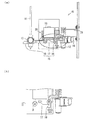
本発明の媒体処理装置に関する実施の一形態であるカッティングプロッタ1の構造について図1及び図2に基づいて説明すれば以下のとおりである。図1はカッティングプロッタ1の構造を模式的に示す図であり、図2はカッティングプロッタ1が備えるキャリッジ10の構造を模式的に示す図であり、図2の(a)は支持体20を示した場合の図であり、図2の(b)は、図2の(a)の丸で囲った位置の周辺の構造を示しており、支持体20を透過している。
[Structure of cutting plotter 1]
The structure of the cutting plotter 1 which is an embodiment of the medium processing apparatus of the present invention will be described below with reference to FIGS. FIG. 1 is a diagram schematically showing the structure of the cutting plotter 1, FIG. 2 is a diagram schematically showing the structure of a
図1に示すようにカッティングプロッタ1はキャリッジ10を備えている。また、カッティングプロッタ1には突出部21(第1の突出部)、突出部22(第2の突出部)が設けられている。
As shown in FIG. 1, the cutting plotter 1 includes a
キャリッジ10は矢印A方向に往復移動する。カッティングプロッタ1により、紙(媒体;図示せず)を処理するとき、キャリッジ10は往復移動しながら、保持しているペン11(第1の処理手段)及びカッター12(第2の処理手段)によって、紙に対して作画及び切断の処理を行なう。なお、本発明に係る媒体処理装置が対象とする媒体は、例えば、型紙用及び段ボール等の紙、樹脂板等が挙げられる。
The
紙はキャリッジ10の直下に配置され、図面を見て奥側から手前側に送られる。つまり、カッティングプロッタ1は紙を或る方向に送りながら、当該方向とは垂直な方向にキャリッジ10を往復移動させる。カッティングプロッタ1には、紙に対して何を作図し、どのように切断するかのデータが予め記録されており、このデータに基づいて紙及びキャリッジ10の移動及びペン11及びカッター12による処理が行なわれる。
The paper is arranged directly under the
図2に示すようにキャリッジ10は、ペンホルダ13(第1の保持手段)、カッターホルダ14(第2の保持手段)、切り替え部15(距離変更手段)、ソレノイド19(上下位置制御手段)、支持体20を備えている。
As shown in FIG. 2, the
ペンホルダ13はペン11を保持するものである。図2はペンホルダ13がペン11を保持している状態を示している。ペンホルダ13のペン11を保持する箇所は円筒状になっており、ペン11は円筒の中を貫通している状態で固定されている。
The
ペンホルダ13は後述する切り替え部15の動作により回動して上下動することができる。
The
カッターホルダ14はカッター12を保持するものである。図2はカッターホルダ14がカッター12を保持している状態を示している。カッター12は円柱状の構造物の先に刃が設けられたものである。カッターホルダ14のカッター12を保持する箇所は円筒状になっており、カッター12は円筒の中を貫通している状態で固定されている。
The
後述のように、ソレノイド19と切り替え部15との間にはソレノイド19の力を切り替え部15に伝達する支持体20が存在しており、カッターホルダ14も支持体20と接続して固定されている。つまり、カッターホルダ14と支持体20との相対的な位置は変わらない。ペンホルダ13の方が上下動することにより、カッター12と紙との距離に比べてペン11と紙との距離を近づけたり遠ざけたりすることができる。
As will be described later, there is a
このように本実施形態では、カッター12の支持体20に対する位置が固定されており、ペン11の位置が上下動する。このように一方の処理手段の位置を回転移動させ、他方の処理手段の位置を回転移動させずに固定することで、一方の処理手段と上記媒体との距離を、他方の処理手段と上記媒体との距離に比べて、近づけたり遠ざけたりする場合、切断処理をするような媒体に対して押し付ける力の強いもの、及び加工精度を必要とするものを回転移動させない非可動部に保持させ、本実施形態でいうペンホルダ13のような回転移動させる可動部に、作画具等の媒体に対して押し付ける力が弱くてよいもの、及び比較的加工精度が低くてよいものを保持させることが好ましい。可動部にかかる力を極力小さくすることで、可動部を構成する部材を細く、薄くすることができ、キャリッジを軽量化することができる。
Thus, in this embodiment, the position of the
切り替え部15は、スイッチ16、軸部17、スイッチ18から構成されている。切り替え部18は、ペン11及びカッター12のうちの一方と紙との距離を、他方と紙との距離に比べて、近づけたり遠ざけたりするものである。例えば、ペン11と紙との距離を、カッター12と紙との距離に比べて近づけたり遠ざけたりする。ペン11と紙との距離が、カッター12と紙との距離に比べて近ければ、紙に対してペン11による作画を行なうことができる。ペン11と紙との距離が、カッター12と紙との距離に比べて遠ければ、紙に対してカッター12により切断することができる。
The switching
スイッチ16は略S字構造をしている。下部がフック構造になっており、軸部17の先端がフックに嵌ることで軸部17を支えている。スイッチ16は、上部にキャリッジ10からみて外側からの力が加わると、図面に対して反時計回りに回転し、軸部17を支えているフックが軸部17の先端から離れる。これにより軸部17のスイッチ16側の端が下方向に動く。
The
軸部17は、回転軸Bを軸として回転する。回転軸Bは、軸部17を通り、軸部17の長手方向に垂直な直線である。スイッチ16が押されて、軸部17のスイッチ16側の端が下方向に動くと、スイッチ18側の端は上方向に動く。
The
スイッチ18は軸部17のペン11側の端に形成されている部位であり、傾斜面が形成されている。傾斜面に対してキャリッジ10からみて外側からの力が加わると、スイッチ18は上下する。この上下の移動は、回転軸Bを軸とする軸部17の回転移動に伴うものである。つまり、スイッチ18及びこれに設けられているペンホルダ13は回転軸Bを軸として回転することによって上下する。
The
ソレノイド19は、切り替え部15全体の上下方向の位置を制御するものである。ペン11の先端及びカッター12の先端のうち、いずれか下にある方が紙を処理する際に、紙の表面と接するように、支持体20を介して切り替え部15全体を上下動させる。これにより、ペン11及びカッター12のうちいずれか媒体に近い方をさらに媒体に押し付けて、作画又は切断の処理を行なう。
The
ソレノイド19は、ペン11を紙に押し付ける力とカッター12を紙に押し付ける力とをそれぞれ独立して変更することができる。つまり、作画に適した力でペン11を押し付けることができ、切断に適した力でカッター12を紙に押し付けることができる。さらに、紙に近づける方の処理手段の切り替えに同期して、ソレノイド19による駆動力を切り替えるようにすれば、自動的に、処理に適した力を処理手段に加えることができる。なお、本発明に係る媒体処理装置が備える上下位置制御手段はこのような構成に限定されるものではなく、例えば、上下位置制御手段を、処理手段毎に複数備えて、複数の上下位置制御手段の駆動力を処理手段毎に予め固定しておいてもよい。
The
支持体20は、ソレノイド19の力が切り替え部15に加わるように、ソレノイド19がペン11及びカッター12を上下させる力を切り替え部15に伝達する構造物である。支持体20は、切り替え部15に接続している。より具体的には、切り替え部15とは、軸部17の回転軸B及びスイッチ16の回転軸を軸とする回転が担保されるように接続されている。ソレノイド19により、切り替え部15を紙に押し付けたり、切り替え部15全体を持ち上げたりする場合、押し付ける力及び持ち上げる力は支持体20を介して切り替え部15に伝達される。このとき支持体20は、図示しないキャリッジ10内のガイドに沿って上下することにより、ペン11及びカッター12を押し付ける力及び持ち上げる力を切り替え部15に伝達する。そして、切り替え部15を介して、ペン11及びカッター12にソレノイド19による力が伝達されて、ペン11及びカッター12は上下する。
The
また、支持体20はカッターホルダ14を支持している。つまり、支持体20はカッターホルダ14を介してカッター12の位置を固定する。これにより、カッター12を紙に対して押し付ける力をソレノイド19から直接加えることができ、加工精度を上げることができる。また、カッターホルダ14を保持する部材を別途設ける必要がなく簡単な機構で軽量化できる。なお、支持体20は、本発明に係る媒体処理装置において、処理手段のうちの一方を距離変更手段以外の部材に固定する場合の当該部材に相当する。
The
〔カッティングプロッタ1の動作〕
次に、図2〜図5を用いてカッティングプロッタ1の動作について説明する。図3〜図5は、それぞれ、カッティングプロッタ1の動作の一例を模式的に示す図であり、図3〜図5の(a)は支持体20を示した場合の図であり、図3〜図5の(b)は、図3〜図5のそれぞれの(a)の丸で囲った位置の周辺の構造を示しており、支持体20を透過している。
[Operation of cutting plotter 1]
Next, the operation of the cutting plotter 1 will be described with reference to FIGS. 3 to 5 are diagrams schematically showing an example of the operation of the cutting plotter 1, and FIG. 3 to FIG. 5A are diagrams showing the
まず、カッティングプロッタ1が紙に対して作画するときの動作について説明する。図2に示すようにペン11の先端がカッター12の先端よりも下に位置している。つまり、ペン11の先端の方がカッター12の先端よりもキャリッジ10の下に配置された紙(図示せず)に近い。カッティングプロッタ1は紙を図面の紙面に対して手前側に送る。その間、キャリッジ10は図1に示す矢印Aの方向に往復移動する。予め設定されたデータ通りに作画されるように、紙の送り及びキャリッジ10の往復移動の間、ソレノイド19が支持体20を介して切り替え部15全体を下に押し、ペン11の先端を紙に接触させる。これにより作画が行なわれる。
First, the operation when the cutting plotter 1 draws on paper will be described. As shown in FIG. 2, the tip of the
なお、キャリッジ10は、常に突出部21及び突出部22が設けられた端まで往復移動するのではなく、紙の幅を当該往復移動可能な幅より狭くした上で、キャリッジ10は当該往復移動する範囲より内側を往復移動することにより、紙を処理する。処理の切り替えを行なうときには、後述のように対応する端までキャリッジ10は移動する。この移動の制御は手動で行なってもよいし、処理内容を示すデータを予め内蔵又は外付けの制御装置に記録させておき、当該データに基づいて、当該制御装置が処理内容に応じてキャリッジ10を移動させてもよい。
The
次に、処理を作画から切断に切り替えて、紙の切断処理をする動作について図3を用いて説明する。 Next, an operation for switching the processing from drawing to cutting and cutting the paper will be described with reference to FIG.
上述のように、紙に作画の処理を行なうときは、キャリッジ10は突出部21及び突出部22より内側で往復移動を行なうが、処理を作画から切断に切り替えるとき、スイッチ16が突出部21によって押される位置までキャリッジ10は移動する。
As described above, when the drawing process is performed on the paper, the
突出部21によってスイッチ16が押されると、突出部21に接した箇所がカッティングプロッタ1の内側方向に移動し、これに伴い、スイッチ16のフック構造の部位がカッティングプロッタ1の外側方向に移動する。この移動の前までは、当該フック構造の部位で軸部17を支えていたが、この移動により、フックが外れて軸部17は支えを失う。その結果、軸部17のスイッチ16側の端が下方向に動き、回転軸Bを軸として軸部17が回動し、軸部17におけるペン11側の端が上方向に回転移動する。これにより、ペン11が持ち上がり、ペン11と紙との距離に比べて、カッター12と紙との距離が近くなる。なお、このとき、フック構造の部位の端は軸部17の端にひっかかり、ペン11が揺れないように固定する機能を果たしている。
When the
このようにカッティングプロッタ1では、ペン11及びカッター12の両方を保持したまま、ペン11及びカッター12のうち処理を行なう方と、紙との距離を他方と紙との距離に比べて容易に近づけることができる。
Thus, in the cutting plotter 1, the distance between the
また、本実施形態では、キャリッジ10の往復移動の幅を広げるだけで、紙に対して行なう処理を、作画から切断に、又は後述のように切断から作画に、容易に切り替えることができる。よって、カッティングプロッタ1の構成は極めて簡易である。
In this embodiment, the processing performed on the paper can be easily switched from drawing to cutting, or from cutting to drawing as described later, simply by widening the reciprocating movement of the
なお、本実施形態では、外れた後のフックが軸部17にひっかかる方向に力が働くようにスイッチ16にはバネが設けられている。また、軸部17の回転移動がスムーズに行なわれるように、予め当該回転移動の方向に力が働くように軸部17にもバネが設けられている。
In the present embodiment, the
以上の動作により、カッティングプロッタ1による処理が紙に対する作図から紙の切断に切り替わる。紙に対する距離が近い方をペン11からカッター12に切り替えた後は、この状態を保ちながら、紙を送り、キャリッジ10を往復移動させる。さらに、切断位置の上にカッター12が位置したときにソレノイド19が切り替え部15全体を下に下げることによってカッター12を紙に押し付ける。これによりカッター12で紙を切断することができる。カッター12による切断を行なうときも、キャリッジ10は突出部21及び突出部22より内側で往復移動を行なう。
With the above operation, the processing by the cutting plotter 1 is switched from drawing on paper to cutting the paper. After switching the one closer to the paper from the
次に、処理を切断から作画に切り替える動作について図4及び図5を用いて説明する。 Next, an operation for switching the processing from cutting to drawing will be described with reference to FIGS.
上述のように、紙の切断処理を行なうときは、キャリッジ10は突出部21及び突出部22より内側で往復移動を行なうが、処理を切断から作画に切り替えるとき、スイッチ18が突出部22によって押される位置までキャリッジ10は移動する。
As described above, when the paper cutting process is performed, the
図4は、スイッチ18が突出部22によって押される寸前の様子を示している。スイッチ18及び突出部22には、互いに面と面とが接することができるように傾斜面が設けられている。上述の通り、この状態まで、スイッチ16のフック構造の部位が軸部17の端にひっかかりペン11の揺れを防止している。
FIG. 4 shows a state immediately before the
次に、キャリッジ10が、より突出部22側に移動すると図5に示すようにスイッチ18が下側に動く。つまり、スイッチ18の傾斜面と突出部22の傾斜面とが接した状態で、さらに互いに近づくことにより、突出部22の傾斜面によってスイッチ18の傾斜面に下方向の力が加わり、スイッチ18が下方向に動く。
Next, when the
これによりペン11が下側に移動する。また、軸部17が回転軸Bを軸として回転することにより、軸部17のスイッチ16側の端が上方向に移動する。さらに、このとき、ソレノイド19は切り替え部15全体を上に引き上げる力を加える。スイッチ16には、バネにより図5に示す位置に戻るように力が加わり続けている。つまり、軸部17の回転、ソレノイド19による切り替え部15の持ち上げにより、軸部17のスイッチ16側の端が上方向に移動した上で、当該端がスイッチ16のフック構造の部分に好適に嵌り、スイッチ16によって支えられる。そして、ペン11がカッター12よりも紙に近い位置になるように切り替え部15が固定される。
As a result, the
その後は、図5に示す状態で紙を送り、キャリッジ10を往復移動させ、作画位置の上にペン11が位置したときにソレノイド19が切り替え部15を下に下げて、ペン11の先端が紙に接触する。これによりペン11で紙に作画することができる。
After that, the paper is fed in the state shown in FIG. 5 and the
以上のように、本実施形態では、切り替え部15が回転軸Bを軸にして回転することで、ペン11と紙との距離に比べたカッター12と紙との距離を近づけたり遠ざけたりする構造について説明した。本発明に係る媒体処理装置が備える距離変更手段は、このような構成に限定されるものではなく、例えば、ペン11及びカッター12をそれぞれ上下動させる構成としてもよい。ただし、本実施形態のように回転を利用して距離を調整する構成は、簡易に形成することができ、部品点数のより多く削減できる。また、装置を小型軽量化することができる。
As described above, in the present embodiment, the switching
また、本実施形態では、キャリッジ10が往復移動する領域の両端に突出部21及び22を設けて、これらにスイッチ16及びスイッチ18を押させることで、処理手段を切り替える構成について説明した。ただし、本発明に係る媒体処理装置はこのような構成には限定されず、例えば、二つの処理手段を上下動させるスイッチをそれぞれ設けて、手動又はアクチュエータ等の機械的な構成でスイッチを押すことで、処理手段を切り替えてもよい。しかしながら、本実施形態のような構成によれば、キャリッジ10に対して複雑な操作をすることなく、簡易に処理手段を切り替えることができ、煩雑な操作及びアクチュエータ等を用いる複雑な機構が不要である。
In the present embodiment, the configuration has been described in which the
また、本実施形態では、カッターホルダ14を、支持体20に固定して回転移動させない構成について説明したが、例えば、軸部17の両端にそれぞれペンホルダ13及びカッターホルダ14を設けるなどして、両方の処理手段が回転移動するようにしてもよい。つまり、この回転移動はペン11が紙に近づくとき、カッター12を紙から遠ざけ、カッター12が紙に近づくとき、ペン11を紙から遠ざける移動である。このような構成であれば、軸部17を回転させることで、ペン11及びカッター12のいずれか目的の処理を行なう方の処理手段を紙に突き出して保持することができる。
In the present embodiment, the configuration in which the
<付記事項>
以上のように、本発明に係る媒体処理装置の一実施形態であるカッティングプロッタ1は、紙に対して、ペン11及びカッター12によって、二種類の処理を行なうものであり、ペン11を保持するペンホルダ13と、カッター12を保持するカッターホルダ14と、ペンホルダ13がペン11を保持し、且つ、カッターホルダ14がカッター12を保持している状態で、ペン11及びカッター12のうちの一方と紙との距離を、他方と紙との距離に比べて、近づけたり遠ざけたりする切り替え部15と、を備える、キャリッジ10を備える。
<Additional notes>
As described above, the cutting plotter 1 which is an embodiment of the medium processing apparatus according to the present invention performs two types of processing on the paper by the
上記の構成によれば、ペン11及びカッター12を共に保持したままで、目的の処理を行なう方の処理手段を媒体に近づけて、処理を行なうことができる。つまり、従来のように、ペンとカッターとを持ち替える機構が不要である。そのため、脱着を確認するための手段及び対応も不要である。そのため、キャリッジ10を小型化できる。また、ペン及びカッターの脱落及び保持不良の対応のために、ペン及びカッターを確実に保持できているか否かを確認する手段も不要であり、処理手段を確実に保持できていない場合の制御機構も不要である。よって、構造が簡単なカッティングプロッタ1を提供できる。
According to the above configuration, it is possible to perform processing by bringing the processing means for performing the target processing closer to the medium while holding both the
また、カッティングプロッタ1では、切り替え部15が、ペン11を回転軸Bを軸に回転移動させることで、ペン11と紙との距離を変更するものである。
Further, in the cutting plotter 1, the switching
例えば、ペン11及びカッター12のそれぞれを独立に上下させる構造等に比べて、簡易な構造で実現できる。つまり、切り替え部15を回転させるだけでペン11及びカッター12のいずれで処理するかを切り替えることができる。よって、カッティングプロッタ1をより簡易な構造とすることができる。また、カッティングプロッタ1を小型で軽量にすることができる。
For example, it can be realized with a simple structure compared to a structure in which each of the
また、カッティングプロッタ1では、ペン11に回転移動をさせるものであり、カッター12は回転移動をせず、支持体20に固定されている。カッティングプロッタ1をより簡易な構造とし、より小型で軽量にすることができる。
In the cutting plotter 1, the
また、カッティングプロッタ1では、キャリッジ10は、ペン11及びカッター12の上下位置を制御するソレノイド19と、ソレノイド19がペン11及びカッター12を上下させる力を伝達する支持体20と、を備えており、回転移動させないカッター12を固定している部材が支持体20である。これにより、カッター12を紙に対して押し付ける力をソレノイド19から直接加えることができ、加工精度を上げることができる。カッターホルダ14を保持する部材を別途設ける必要がなく簡単な機構で軽量化できる。
In the cutting plotter 1, the
また、上述の実施形態とは異なるが、カッティングプロッタ1では、切り替え部15が、ペン11及びカッター12のいずれも回転移動させるものであり、当該回転移動は、ペン11が紙に近づくとき、カッター12を紙から遠ざけ、カッター12が紙に近づくとき、ペン11を紙から遠ざける移動となるように構成してもよい。
Further, although different from the above-described embodiment, in the cutting plotter 1, the switching
回転移動させる部材である軸部17にペン11及びカッター12を取り付けて回転させるだけで、所望の処理手段を紙に近づけることができる。
The desired processing means can be brought closer to the paper simply by attaching the
また、キャリッジ10が紙上を往復移動するものであり、切り替え部15は、スイッチ16及びスイッチ18を備えており、スイッチ16を押すことによって、カッター12と紙との距離を、ペン11と紙との距離に比べて近づけ、スイッチ18を押すことによって、カッター12と紙との距離を、ペン11と紙との距離に比べて遠ざけるものであり、往復移動によってキャリッジ10が一方の端に到達したときに、スイッチ16が押される位置に突出部21が設けられており、キャリッジ10が他方の端に到達したときに、スイッチ18が押される位置に突出部22が設けられている。
The
目的とする処理を切り替えるとき、対応する端までキャリッジ10を移動させれば、処理を切り替えることができる。よって、より容易に処理を切り替えることができる。
When switching the target process, the process can be switched by moving the
また、カッティングプロッタ1では、キャリッジ10は、ペン11及びカッター12の上下位置を制御するソレノイド19を備えており、ソレノイド19は、ペン11及びカッター12のうち紙に近い方を紙に押し付ける力を、ペン11を紙に押し付けるときとカッター12を紙に押し付けるときとで変更するものである。これにより、所望の処理に適した押し付け力で処理を行なうことができる。
Further, in the cutting plotter 1, the
また、カッティングプロッタ1では、ペン11が紙に作画するものであり、カッター12が紙を切断するものであるので、例えば、型紙の製造等のように、媒体に対して作画及び切断を行なう装置として好適に用いることができる。
Further, in the cutting plotter 1, since the
本発明は上述した各実施形態に限定されるものではなく、請求項に示した範囲で種々の変更が可能であり、異なる実施形態にそれぞれ開示された技術的手段を適宜組み合わせて得られる実施形態についても本発明の技術的範囲に含まれる。 The present invention is not limited to the above-described embodiments, and various modifications are possible within the scope shown in the claims, and embodiments obtained by appropriately combining technical means disclosed in different embodiments. Is also included in the technical scope of the present invention.
本発明に係る媒体処理装置は、アパレル製品の型紙作成等に好適に利用することができる。 The medium processing apparatus according to the present invention can be suitably used for making paper patterns for apparel products.
1 カッティングプロッタ(媒体処理装置)
10 キャリッジ
11 ペン(第1の処理手段)
12 カッター(第2の処理手段)
13 ペンホルダ(第1の保持手段)
14 カッターホルダ(第2の保持手段)
15 切り替え部(距離変更手段)
16、18 スイッチ
19 ソレノイド(上下位置制御手段)
20 支持体
21 突出部(第1の突出部)
22 突出部(第2の突出部)
1 Cutting plotter (media processing device)
10
12 Cutter (second processing means)
13 Pen holder (first holding means)
14 Cutter holder (second holding means)
15 switching part (distance changing means)
16, 18
20
22 Protrusion (second protrusion)
Claims (11)
上記第1の処理手段を保持する第1の保持手段と、
上記第2の処理手段を保持する第2の保持手段と、
上記第1の保持手段が上記第1の処理手段を保持し、且つ、上記第2の保持手段が上記第2の処理手段を保持している状態で、一方の処理手段と上記媒体との距離を、他方の処理手段と上記媒体との距離に比べて、近づけたり遠ざけたりする距離変更手段と、
を備える、キャリッジを備え、
上記距離変更手段が、上記第1の処理手段及び第2の処理手段のうち一方の処理手段を或る回転軸を軸に回転移動をさせることで、当該一方の処理手段と上記媒体との距離を変更するものであり、上記距離変更手段が、上記第1の処理手段及び第2の処理手段のいずれも回転移動させるものであり、当該回転移動は、上記第1の処理手段が上記媒体に近づくとき、上記第2の処理手段を上記媒体から遠ざけ、上記第2の処理手段が上記媒体に近づくとき、上記第1の処理手段を上記媒体から遠ざける移動であることを特徴とする媒体処理装置。 The medium is subjected to at least two types of processing by the first processing means and the second processing means,
First holding means for holding the first processing means;
Second holding means for holding the second processing means;
The distance between one processing means and the medium in a state where the first holding means holds the first processing means and the second holding means holds the second processing means. A distance changing means for moving the distance closer to or away from the distance between the other processing means and the medium;
Comprising a carriage comprising
The distance changing means rotates one of the first processing means and the second processing means about a certain rotation axis to thereby move the distance between the one processing means and the medium. The distance changing means rotates both the first processing means and the second processing means, and the rotational movement is performed by the first processing means on the medium. A medium processing apparatus characterized in that when moving closer, the second processing means moves away from the medium, and when the second processing means approaches the medium, the first processing means moves away from the medium. .
上記第1の処理手段を保持する第1の保持手段と、
上記第2の処理手段を保持する第2の保持手段と、
上記第1の保持手段が上記第1の処理手段を保持し、且つ、上記第2の保持手段が上記第2の処理手段を保持している状態で、一方の処理手段と上記媒体との距離を、他方の処理手段と上記媒体との距離に比べて、近づけたり遠ざけたりする距離変更手段と、
を備える、キャリッジを備え、
上記キャリッジが媒体上を往復移動するものであり、
上記距離変更手段は、2つのスイッチを備えており、一方のスイッチを押すことによって、一方の処理手段と上記媒体との距離を、他方の処理手段と上記媒体との距離に比べて
近づけ、他方のスイッチを押すことによって、当該一方の処理手段と上記媒体との距離を、当該他方の処理手段と上記媒体との距離に比べて遠ざけるものであり、
上記往復移動によって上記キャリッジが一方の端に到達したときに、一方のスイッチが押される位置に第1の突出部が設けられており、上記キャリッジが他方の端に到達したときに、他方のスイッチが押される位置に第2の突出部が設けられていることを特徴とする媒体処理装置。 The medium is subjected to at least two types of processing by the first processing means and the second processing means,
First holding means for holding the first processing means;
Second holding means for holding the second processing means;
The distance between one processing means and the medium in a state where the first holding means holds the first processing means and the second holding means holds the second processing means. A distance changing means for moving the distance closer to or away from the distance between the other processing means and the medium;
Comprising a carriage comprising
The carriage reciprocates on the medium;
The distance changing means includes two switches. By pressing one of the switches, the distance between one processing means and the medium is made shorter than the distance between the other processing means and the medium. By pushing the switch, the distance between the one processing means and the medium is increased compared to the distance between the other processing means and the medium.
A first protrusion is provided at a position where one switch is pressed when the carriage reaches one end by the reciprocating movement, and when the carriage reaches the other end, the other switch A medium processing apparatus, wherein a second protrusion is provided at a position where the button is pressed.
上記第1の処理手段を保持する第1の保持手段と、
上記第2の処理手段を保持する第2の保持手段と、
上記第1の保持手段が上記第1の処理手段を保持し、且つ、上記第2の保持手段が上記第2の処理手段を保持している状態で、一方の処理手段と上記媒体との距離を、他方の処理手段と上記媒体との距離に比べて、近づけたり遠ざけたりする距離変更手段と、
を備える、キャリッジを備え、
上記距離変更手段が、上記第1の処理手段及び第2の処理手段のうち一方の処理手段を或る回転軸を軸に回転移動をさせることで、当該一方の処理手段と上記媒体との距離を変更するものであり、
上記距離変更手段は、一方の処理手段に上記回転移動をさせるものであり、
他方の処理手段は回転移動をせず、上記距離変更手段以外の部材に固定されており、
上記キャリッジは、上記第1の処理手段及び上記第2の処理手段の上下位置を制御する上下位置制御手段と、上記上下位置制御手段が上記第1の処理手段及び上記第2の処理手段を上下させる力を伝達する支持体と、を備えており、
回転移動させない上記他方の処理手段を固定する上記距離変更手段以外の部材が上記支持体であり、
上記上下位置制御手段が一つのソレノイドであることを特徴とする媒体処理装置。 The medium is subjected to at least two types of processing by the first processing means and the second processing means,
First holding means for holding the first processing means;
Second holding means for holding the second processing means;
The distance between one processing means and the medium in a state where the first holding means holds the first processing means and the second holding means holds the second processing means. A distance changing means for moving the distance closer to or away from the distance between the other processing means and the medium;
Comprising a carriage comprising
The distance changing means rotates one of the first processing means and the second processing means about a certain rotation axis to thereby move the distance between the one processing means and the medium. Is to change
The distance changing means causes one of the processing means to perform the rotational movement,
The other processing means does not rotate and is fixed to a member other than the distance changing means,
The carriage includes a vertical position control means for controlling the vertical position of the first processing means and the second processing means, and the vertical position control means moves the first processing means and the second processing means up and down. A support for transmitting the force to be
A member other than the distance changing means for fixing the other processing means not to be rotated is the support.
The medium processing apparatus, wherein the vertical position control means is a single solenoid.
上記第1の処理手段を保持する第1の保持手段と、
上記第2の処理手段を保持する第2の保持手段と、
上記第1の保持手段が上記第1の処理手段を保持し、且つ、上記第2の保持手段が上記第2の処理手段を保持している状態で、一方の処理手段と上記媒体との距離を、他方の処理手段と上記媒体との距離に比べて、近づけたり遠ざけたりする距離変更手段と、
を備える、キャリッジを備え、
上記キャリッジは、上記第1の処理手段及び上記第2の処理手段の上下位置を制御する上下位置制御手段を備えており、
上記上下位置制御手段は、上記第1の処理手段及び上記第2の処理手段のうち上記媒体に近い方を上記媒体に押し付ける力を、上記第1の処理手段を上記媒体に押し付けるときと上記第2の処理手段を上記媒体に押し付けるときとで変更するものであり、
上記上下位置制御手段が一つのソレノイドであることを特徴とする媒体処理装置。 The medium is subjected to at least two types of processing by the first processing means and the second processing means,
First holding means for holding the first processing means;
Second holding means for holding the second processing means;
The distance between one processing means and the medium in a state where the first holding means holds the first processing means and the second holding means holds the second processing means. A distance changing means for moving the distance closer to or away from the distance between the other processing means and the medium;
Comprising a carriage comprising
The carriage includes vertical position control means for controlling vertical positions of the first processing means and the second processing means,
The vertical position control means is configured to apply a force that presses the medium closer to the medium out of the first processing means and the second processing means when the first processing means is pressed against the medium. 2 when the processing means 2 is pressed against the medium.
The medium processing apparatus, wherein the vertical position control means is a single solenoid.
他方の処理手段は回転移動をせず、上記距離変更手段以外の部材に固定されていることを特徴とする請求項5に記載の媒体処理装置。 The distance changing means causes one of the processing means to perform the rotational movement,
6. The medium processing apparatus according to claim 5, wherein the other processing unit does not rotate and is fixed to a member other than the distance changing unit.
回転移動させない上記他方の処理手段を固定する上記距離変更手段以外の部材が上記支持体であることを特徴とする請求項6に記載の媒体処理装置。 The carriage includes a vertical position control means for controlling the vertical position of the first processing means and the second processing means, and the vertical position control means moves the first processing means and the second processing means up and down. A support for transmitting the force to be
7. The medium processing apparatus according to claim 6, wherein a member other than the distance changing means for fixing the other processing means that is not rotated is the support.
上記距離変更手段は、2つのスイッチを備えており、一方のスイッチを押すことによって、一方の処理手段と上記媒体との距離を、他方の処理手段と上記媒体との距離に比べて近づけ、他方のスイッチを押すことによって、当該一方の処理手段と上記媒体との距離を、当該他方の処理手段と上記媒体との距離に比べて遠ざけるものであり、
上記往復移動によって上記キャリッジが一方の端に到達したときに、一方のスイッチが押される位置に第1の突出部が設けられており、上記キャリッジが他方の端に到達したときに、他方のスイッチが押される位置に第2の突出部が設けられていることを特徴とする請求項1、3又は4に記載の媒体処理装置。 The carriage reciprocates on the medium;
The distance changing means includes two switches. By pressing one of the switches, the distance between one processing means and the medium is made shorter than the distance between the other processing means and the medium. By pushing the switch, the distance between the one processing means and the medium is increased compared to the distance between the other processing means and the medium.
A first protrusion is provided at a position where one switch is pressed when the carriage reaches one end by the reciprocating movement, and when the carriage reaches the other end, the other switch The medium processing apparatus according to claim 1, wherein the second protrusion is provided at a position where the button is pressed.
上記上下位置制御手段は、上記第1の処理手段及び上記第2の処理手段のうち上記媒体に近い方を上記媒体に押し付ける力を、上記第1の処理手段を上記媒体に押し付けるときと上記第2の処理手段を上記媒体に押し付けるときとで変更するものであることを特徴とする請求項1〜3のいずれか1項に記載の媒体処理装置。 The carriage includes vertical position control means for controlling vertical positions of the first processing means and the second processing means,
The vertical position control means is configured to apply a force that presses the medium closer to the medium out of the first processing means and the second processing means when the first processing means is pressed against the medium. The medium processing apparatus according to claim 1, wherein the medium processing apparatus is changed when the two processing units are pressed against the medium.
11. The method according to claim 1, wherein one of the first processing means and the second processing means draws on the medium, and the other cuts the medium. 2. The medium processing apparatus according to item 1.
Priority Applications (5)
| Application Number | Priority Date | Filing Date | Title |
|---|---|---|---|
| JP2011132642A JP5717552B2 (en) | 2011-06-10 | 2011-06-14 | Media processing device |
| EP12170897.8A EP2533174B1 (en) | 2011-06-10 | 2012-06-05 | Medium processing device |
| US13/490,446 US8887403B2 (en) | 2011-06-10 | 2012-06-06 | Medium processing device |
| CN201210189728.4A CN102825918B (en) | 2011-06-10 | 2012-06-08 | Medium processing device |
| KR1020120061477A KR101442664B1 (en) | 2011-06-10 | 2012-06-08 | Medium processing apparatus |
Applications Claiming Priority (3)
| Application Number | Priority Date | Filing Date | Title |
|---|---|---|---|
| JP2011130181 | 2011-06-10 | ||
| JP2011130181 | 2011-06-10 | ||
| JP2011132642A JP5717552B2 (en) | 2011-06-10 | 2011-06-14 | Media processing device |
Publications (2)
| Publication Number | Publication Date |
|---|---|
| JP2013014005A JP2013014005A (en) | 2013-01-24 |
| JP5717552B2 true JP5717552B2 (en) | 2015-05-13 |
Family
ID=46197144
Family Applications (1)
| Application Number | Title | Priority Date | Filing Date |
|---|---|---|---|
| JP2011132642A Active JP5717552B2 (en) | 2011-06-10 | 2011-06-14 | Media processing device |
Country Status (5)
| Country | Link |
|---|---|
| US (1) | US8887403B2 (en) |
| EP (1) | EP2533174B1 (en) |
| JP (1) | JP5717552B2 (en) |
| KR (1) | KR101442664B1 (en) |
| CN (1) | CN102825918B (en) |
Families Citing this family (2)
| Publication number | Priority date | Publication date | Assignee | Title |
|---|---|---|---|---|
| JP2012254608A (en) * | 2011-06-10 | 2012-12-27 | Mimaki Engineering Co Ltd | Medium processing device |
| CN111615456B (en) * | 2018-01-31 | 2022-03-29 | 惠普发展公司,有限责任合伙企业 | Cutter assembly with movable slot cover |
Family Cites Families (21)
| Publication number | Priority date | Publication date | Assignee | Title |
|---|---|---|---|---|
| JPS582638Y2 (en) * | 1976-05-27 | 1983-01-17 | セイコーインスツルメンツ株式会社 | pen support device |
| US4228570A (en) * | 1979-10-15 | 1980-10-21 | Photon Power, Inc. | Electroding preparation apparatus |
| US4709483A (en) * | 1984-03-14 | 1987-12-01 | Wing Aero | Glass cutting device |
| US4640222A (en) * | 1985-05-23 | 1987-02-03 | Gerber Scientific Inc. | Marking apparatus |
| US4577409A (en) * | 1985-05-24 | 1986-03-25 | Hitachi, Ltd. | Pen changing apparatus for plotter |
| JP2514833B2 (en) * | 1988-07-27 | 1996-07-10 | グラフテック株式会社 | Automatic paper cutting machine for recording device |
| JPH0712068Y2 (en) * | 1988-11-30 | 1995-03-22 | 武藤工業株式会社 | Paper cutting device for automatic drafting machine |
| JP2828475B2 (en) * | 1990-01-12 | 1998-11-25 | グラフテック株式会社 | Lifting device for cutter for recording device |
| JPH04182199A (en) * | 1990-11-16 | 1992-06-29 | Mutoh Ind Ltd | Drawing and cutting method for air permeable sheet in automatic drawing machine |
| US5383277A (en) * | 1992-03-10 | 1995-01-24 | Max Co., Ltd. | Writing apparatus and method |
| JP3157339B2 (en) | 1993-03-15 | 2001-04-16 | 株式会社ミマキエンジニアリング | Pen exchange mechanism |
| JP3433995B2 (en) * | 1993-12-28 | 2003-08-04 | シチズン時計株式会社 | Cutter device and printer device having the same |
| US5482389A (en) * | 1994-11-25 | 1996-01-09 | Westerex International, Division Of Capitol Circuits | Paper feed driven cutter mechanism of an electronic printer |
| JP3675875B2 (en) | 1995-02-22 | 2005-07-27 | グラフテック株式会社 | Recording medium cutting mechanism of recording apparatus |
| JP3673310B2 (en) * | 1995-11-16 | 2005-07-20 | 武藤工業株式会社 | Plotter |
| JP2001212790A (en) * | 2000-02-03 | 2001-08-07 | Graphtec Corp | Plotter |
| JP3805273B2 (en) * | 2002-03-29 | 2006-08-02 | Uht株式会社 | Multilayer electronic component manufacturing equipment |
| CN2652620Y (en) * | 2003-07-01 | 2004-11-03 | 湘潭大学 | Digital control flat plate type drawing cutter |
| CN100398257C (en) * | 2004-11-02 | 2008-07-02 | 湘潭大学 | Flatbed CNC cutting and plotting machine linkage head |
| CN201388578Y (en) * | 2009-04-29 | 2010-01-27 | 向伯安 | Flat plate type clothing pattern machine |
| JP2012012731A (en) * | 2010-07-01 | 2012-01-19 | Brother Ind Ltd | Sewing machine |
-
2011
- 2011-06-14 JP JP2011132642A patent/JP5717552B2/en active Active
-
2012
- 2012-06-05 EP EP12170897.8A patent/EP2533174B1/en active Active
- 2012-06-06 US US13/490,446 patent/US8887403B2/en active Active
- 2012-06-08 KR KR1020120061477A patent/KR101442664B1/en not_active Expired - Fee Related
- 2012-06-08 CN CN201210189728.4A patent/CN102825918B/en active Active
Also Published As
| Publication number | Publication date |
|---|---|
| US8887403B2 (en) | 2014-11-18 |
| US20120312228A1 (en) | 2012-12-13 |
| CN102825918A (en) | 2012-12-19 |
| KR20120137286A (en) | 2012-12-20 |
| JP2013014005A (en) | 2013-01-24 |
| CN102825918B (en) | 2014-12-03 |
| EP2533174A1 (en) | 2012-12-12 |
| KR101442664B1 (en) | 2014-09-23 |
| EP2533174B1 (en) | 2017-08-16 |
Similar Documents
| Publication | Publication Date | Title |
|---|---|---|
| US8459887B2 (en) | Cutter device and printing apparatus | |
| US8807855B2 (en) | Apparatus for cutting a medium | |
| JP2008209303A (en) | Automatic slicer | |
| CN103625133B (en) | Print apparatus | |
| JP5717552B2 (en) | Media processing device | |
| JP2012135930A (en) | Label sheet transfer device in label cutting device for in-mold label molding and label sheet transfer method | |
| JP2005169958A (en) | Printer | |
| CN104859316B (en) | Disk cutter sweep | |
| EP1935656B1 (en) | Printing apparatus | |
| KR101401520B1 (en) | Medium processing apparatus | |
| CN103658997B (en) | Laser cutter material-frame locating device | |
| JP5521167B2 (en) | Cutting device | |
| JP2020142351A (en) | Image forming device | |
| JP4344253B2 (en) | Bookbinding equipment | |
| JP6625721B1 (en) | Cutting machine | |
| JP5985375B2 (en) | Cutting plotter | |
| JP2020142350A (en) | Image forming device | |
| JP2021509362A (en) | Media cutting device and method | |
| JP2015226937A (en) | Cutting device, cutting control method, and program | |
| JP2013111693A (en) | Carriage mechanism of processing device | |
| JP2013176866A (en) | Printing apparatus | |
| JP2019034434A (en) | Liquid discharge device | |
| JP2014050984A (en) | Ink color developing device and ink color developing method |
Legal Events
| Date | Code | Title | Description |
|---|---|---|---|
| A621 | Written request for application examination |
Free format text: JAPANESE INTERMEDIATE CODE: A621 Effective date: 20140123 |
|
| A977 | Report on retrieval |
Free format text: JAPANESE INTERMEDIATE CODE: A971007 Effective date: 20140912 |
|
| A131 | Notification of reasons for refusal |
Free format text: JAPANESE INTERMEDIATE CODE: A131 Effective date: 20141028 |
|
| A521 | Request for written amendment filed |
Free format text: JAPANESE INTERMEDIATE CODE: A523 Effective date: 20141223 |
|
| A131 | Notification of reasons for refusal |
Free format text: JAPANESE INTERMEDIATE CODE: A131 Effective date: 20150120 |
|
| A521 | Request for written amendment filed |
Free format text: JAPANESE INTERMEDIATE CODE: A523 Effective date: 20150206 |
|
| TRDD | Decision of grant or rejection written | ||
| A01 | Written decision to grant a patent or to grant a registration (utility model) |
Free format text: JAPANESE INTERMEDIATE CODE: A01 Effective date: 20150224 |
|
| A61 | First payment of annual fees (during grant procedure) |
Free format text: JAPANESE INTERMEDIATE CODE: A61 Effective date: 20150317 |
|
| R150 | Certificate of patent or registration of utility model |
Ref document number: 5717552 Country of ref document: JP Free format text: JAPANESE INTERMEDIATE CODE: R150 |
|
| R250 | Receipt of annual fees |
Free format text: JAPANESE INTERMEDIATE CODE: R250 |
|
| R250 | Receipt of annual fees |
Free format text: JAPANESE INTERMEDIATE CODE: R250 |
|
| R250 | Receipt of annual fees |
Free format text: JAPANESE INTERMEDIATE CODE: R250 |
|
| R250 | Receipt of annual fees |
Free format text: JAPANESE INTERMEDIATE CODE: R250 |
|
| R250 | Receipt of annual fees |
Free format text: JAPANESE INTERMEDIATE CODE: R250 |
|
| R250 | Receipt of annual fees |
Free format text: JAPANESE INTERMEDIATE CODE: R250 |
|
| R250 | Receipt of annual fees |
Free format text: JAPANESE INTERMEDIATE CODE: R250 |
|
| R250 | Receipt of annual fees |
Free format text: JAPANESE INTERMEDIATE CODE: R250 |
|
| R250 | Receipt of annual fees |
Free format text: JAPANESE INTERMEDIATE CODE: R250 |