EP1935656B1 - Printing apparatus - Google Patents
Printing apparatus Download PDFInfo
- Publication number
- EP1935656B1 EP1935656B1 EP20070253954 EP07253954A EP1935656B1 EP 1935656 B1 EP1935656 B1 EP 1935656B1 EP 20070253954 EP20070253954 EP 20070253954 EP 07253954 A EP07253954 A EP 07253954A EP 1935656 B1 EP1935656 B1 EP 1935656B1
- Authority
- EP
- European Patent Office
- Prior art keywords
- cutter
- printer
- medium
- tape
- cutting
- Prior art date
- Legal status (The legal status is an assumption and is not a legal conclusion. Google has not performed a legal analysis and makes no representation as to the accuracy of the status listed.)
- Active
Links
- 238000007639 printing Methods 0.000 title claims description 22
- 238000005520 cutting process Methods 0.000 claims description 76
- 230000007246 mechanism Effects 0.000 claims description 44
- 238000000034 method Methods 0.000 claims description 11
- 230000001419 dependent effect Effects 0.000 claims 2
- 239000010410 layer Substances 0.000 description 9
- 239000012790 adhesive layer Substances 0.000 description 4
- 230000008901 benefit Effects 0.000 description 2
- 230000000994 depressogenic effect Effects 0.000 description 2
- 238000010586 diagram Methods 0.000 description 2
- 239000000853 adhesive Substances 0.000 description 1
- 230000001070 adhesive effect Effects 0.000 description 1
- 230000008859 change Effects 0.000 description 1
- 238000013479 data entry Methods 0.000 description 1
- 230000000694 effects Effects 0.000 description 1
- 230000006870 function Effects 0.000 description 1
- 230000003993 interaction Effects 0.000 description 1
- 230000001788 irregular Effects 0.000 description 1
- 239000004973 liquid crystal related substance Substances 0.000 description 1
- 239000000463 material Substances 0.000 description 1
- 238000012986 modification Methods 0.000 description 1
- 230000004048 modification Effects 0.000 description 1
- 230000004044 response Effects 0.000 description 1
- 238000010023 transfer printing Methods 0.000 description 1
Images


Classifications
-
- B—PERFORMING OPERATIONS; TRANSPORTING
- B41—PRINTING; LINING MACHINES; TYPEWRITERS; STAMPS
- B41J—TYPEWRITERS; SELECTIVE PRINTING MECHANISMS, i.e. MECHANISMS PRINTING OTHERWISE THAN FROM A FORME; CORRECTION OF TYPOGRAPHICAL ERRORS
- B41J11/00—Devices or arrangements of selective printing mechanisms, e.g. ink-jet printers or thermal printers, for supporting or handling copy material in sheet or web form
- B41J11/66—Applications of cutting devices
- B41J11/70—Applications of cutting devices cutting perpendicular to the direction of paper feed
- B41J11/703—Cutting of tape
-
- B—PERFORMING OPERATIONS; TRANSPORTING
- B26—HAND CUTTING TOOLS; CUTTING; SEVERING
- B26D—CUTTING; DETAILS COMMON TO MACHINES FOR PERFORATING, PUNCHING, CUTTING-OUT, STAMPING-OUT OR SEVERING
- B26D1/00—Cutting through work characterised by the nature or movement of the cutting member or particular materials not otherwise provided for; Apparatus or machines therefor; Cutting members therefor
- B26D1/01—Cutting through work characterised by the nature or movement of the cutting member or particular materials not otherwise provided for; Apparatus or machines therefor; Cutting members therefor involving a cutting member which does not travel with the work
- B26D1/12—Cutting through work characterised by the nature or movement of the cutting member or particular materials not otherwise provided for; Apparatus or machines therefor; Cutting members therefor involving a cutting member which does not travel with the work having a cutting member moving about an axis
- B26D1/25—Cutting through work characterised by the nature or movement of the cutting member or particular materials not otherwise provided for; Apparatus or machines therefor; Cutting members therefor involving a cutting member which does not travel with the work having a cutting member moving about an axis with a non-circular cutting member
- B26D1/26—Cutting through work characterised by the nature or movement of the cutting member or particular materials not otherwise provided for; Apparatus or machines therefor; Cutting members therefor involving a cutting member which does not travel with the work having a cutting member moving about an axis with a non-circular cutting member moving about an axis substantially perpendicular to the line of cut
- B26D1/30—Cutting through work characterised by the nature or movement of the cutting member or particular materials not otherwise provided for; Apparatus or machines therefor; Cutting members therefor involving a cutting member which does not travel with the work having a cutting member moving about an axis with a non-circular cutting member moving about an axis substantially perpendicular to the line of cut with limited pivotal movement to effect cut
- B26D1/305—Cutting through work characterised by the nature or movement of the cutting member or particular materials not otherwise provided for; Apparatus or machines therefor; Cutting members therefor involving a cutting member which does not travel with the work having a cutting member moving about an axis with a non-circular cutting member moving about an axis substantially perpendicular to the line of cut with limited pivotal movement to effect cut for thin material, e.g. for sheets, strips or the like
-
- B—PERFORMING OPERATIONS; TRANSPORTING
- B26—HAND CUTTING TOOLS; CUTTING; SEVERING
- B26D—CUTTING; DETAILS COMMON TO MACHINES FOR PERFORATING, PUNCHING, CUTTING-OUT, STAMPING-OUT OR SEVERING
- B26D5/00—Arrangements for operating and controlling machines or devices for cutting, cutting-out, stamping-out, punching, perforating, or severing by means other than cutting
- B26D5/08—Means for actuating the cutting member to effect the cut
- B26D5/14—Crank and pin means
-
- Y—GENERAL TAGGING OF NEW TECHNOLOGICAL DEVELOPMENTS; GENERAL TAGGING OF CROSS-SECTIONAL TECHNOLOGIES SPANNING OVER SEVERAL SECTIONS OF THE IPC; TECHNICAL SUBJECTS COVERED BY FORMER USPC CROSS-REFERENCE ART COLLECTIONS [XRACs] AND DIGESTS
- Y10—TECHNICAL SUBJECTS COVERED BY FORMER USPC
- Y10T—TECHNICAL SUBJECTS COVERED BY FORMER US CLASSIFICATION
- Y10T83/00—Cutting
- Y10T83/869—Means to drive or to guide tool
- Y10T83/8789—With simple revolving motion only
- Y10T83/8796—Progressively cutting
-
- Y—GENERAL TAGGING OF NEW TECHNOLOGICAL DEVELOPMENTS; GENERAL TAGGING OF CROSS-SECTIONAL TECHNOLOGIES SPANNING OVER SEVERAL SECTIONS OF THE IPC; TECHNICAL SUBJECTS COVERED BY FORMER USPC CROSS-REFERENCE ART COLLECTIONS [XRACs] AND DIGESTS
- Y10—TECHNICAL SUBJECTS COVERED BY FORMER USPC
- Y10T—TECHNICAL SUBJECTS COVERED BY FORMER US CLASSIFICATION
- Y10T83/00—Cutting
- Y10T83/869—Means to drive or to guide tool
- Y10T83/8798—With simple oscillating motion only
- Y10T83/8804—Tool driver movable relative to tool support
- Y10T83/8807—Gear or ratchet pawl drives toothed tool support
Definitions
- the present invention relates to a printing apparatus and to a method of cutting an image receiving medium.
- the present invention relates to a tape printing apparatus having a cutter arranged to cut the tape, so that the tape forms a label.
- Tape printers which use a supply of tape, housed in a cassette received in the tape printer.
- the tape comprises an image receiving layer and a backing layer which are secured to one another via an adhesive layer. After an image has been printed onto the image receiving layer, the backing layer can be removed allowing the image receiving layer to be secured to an object using the adhesive layer.
- Such tape printers include a cutting mechanism for cutting off a portion of the tape after an image has been printed onto the image receiving layer so that the portion of tape can be used as a label.
- the cutting mechanism includes a blade which is intended to cut through all the layers of the tape.
- the cutting mechanism in these known tape printers can be operated by the user manually. Alternatively the cutting mechanism may be driven by a motor in the tape printer.
- Some examples of automatic cutting mechanisms are described in EP-A-534799 , EP-A-929402 , EP-A-764542 and US-A-5599119 .
- An embodiment of an automatic cutter is incorporated into the DYMO PC-10 Electronic Labelmaker.
- the force required to cut the tape may also cause the position of a tape cassette housing the tape to displace during cutting. This causes further problems such as incomplete cutting of the tape, and misalignment of the printed image on the tape in subsequent printing operations.
- EP 0711637 A1 describes a manual printing mechanism wherein an actuating member is driven by an anvil to cut through a tape. A spring is used to return the anvil and actuating member to a start position.
- EP 0798254 A2 describes a device for cutting, cutting off or perforating of paper, pasteboard or the like consisting of a cutting tool led within a framework.
- a printer for printing an image on an image receiving medium comprising: a tape receiving portion for receiving a supply of image receiving medium on which an image is to be printed; a printing mechanism arranged to print an image on said medium; and a cutting mechanism for cutting off a portion of said medium, wherein the cutting mechanism comprises a cutter guide track defining a predetermined path for guiding a cutter of the cutting mechanism during a cutting cycle, wherein during a first portion of the cutting cycle the guide track is arranged to guide the cutter to intersect a plane of the medium such that a portion of the medium is cut off, and wherein during a second portion of the cycle the guide track is arranged to guide the cutter to return to a home position such that the cutter does not intersect the plane of the medium.
- a method of cutting an image receiving medium to form a label comprising; guiding a cutter to move along a predetermined path during a cutting cycle, wherein during a first portion of the cutting cycle the guide track is arranged to guide the cutter to intersect a plane of the medium such that a portion of the medium is cut off, and wherein during a second portion of the cycle the guide track is arranged to guide the cutter to return to a home position such that the cutter does not intersect the plane of the medium.
- FIG 11 shows a schematic diagram of a tape printing apparatus 100 according to an embodiment of the present invention.
- the tape printing apparatus comprises a keyboard 101 and a cassette receiving bay 102.
- the cassette receiving bay 102 houses a cassette containing image receiving tape on which a label is printed.
- the image receiving tape has an image receiving layer for receiving the image and an adhesive layer for allowing the label to be adhered to a surface.
- the keyboard has a plurality of data entry keys 103 such as numbered, lettered and punctuation keys for inputting data to be printed as a label and function keys for editing the input data.
- the keyboard may also have a print key 104 which is operated when it is desired that a label be printed.
- an on/off key 105 is also provided for switching the tape printing apparatus on and off.
- the tape printing apparatus has a liquid crystal display (LCD) 106 which displays the data as it is entered.
- LCD liquid crystal display
- the display allows the user to view all or part of the label to be printed which facilitates the editing of the label prior to its printing. Additionally, the display is driven by a display driver (not shown).
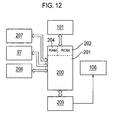
- FIG. 12 Basic circuitry for controlling the tape printing device 100 is shown in Figure 12 .
- a microprocessor chip 200 having a read only memory (ROM) 202, a microprocessor 201 and random access memory capacity indicated diagrammatically by RAM 204.
- the microprocessor chip 200 is connected to receive label data input to it from a data input device such as the keyboard 101.
- the microprocessor chip 200 outputs data to drive the display 106 via a display driver chip 209 to display a label to be printed (or a part thereof) and/or a message for the user.
- the display driver alternatively may form part of the microprocessor chip.
- the microprocessor chip 200 also outputs data to drive a print head 206 so that the label data is printed onto the image receiving tape to form a label.
- the microprocessor chip 200 also controls a motor 207 for driving the tape.
- the microprocessor chip 100 also controls a motor 97 for operating a cutting mechanism 58 to allow a length of tape to be cut off. The manner in which the cutting mechanism is controlled will be discussed hereinafter.
- the tape printer 100 may be arranged print to an image on an image receiving tape using an ink ribbon.
- This method of printing is known as thermal transfer printing.
- Figure 13 shows a schematic diagram of a cassette receiving bay 102 in the tape printing apparatus 100 arranged to print by thermal transfer.
- an ink ribbon cassette 52 containing an ink ribbon 45 is installed together with an image receiving tape cassette 50 in the cassette receiving bay 102.
- the image receiving tape cassette 50 contains a supply of image receiving tape 40 provided on a supply spool 88.
- the cassette bay 102 also accommodates at least one thermal print head 206 and a platen 80 which cooperate to define a print zone 53.
- the print head 206 is able to pivot about a pivot point 54 so that it can be brought into contact with the platen 80 for printing and moved away from the platen 80 to enable the cassette 50 to be removed and replaced.
- the platen 80 is rotated by a motor 207 ( Figure 12 ) to cause the tape 40 to be driven past the print head 206 to the cutting zone 59.
- the ink ribbon 45 passes through the print zone together with the image receiving tape 40.
- the image receiving tape 40 is an ink receiving tape.
- the image receiving tape 40 is a direct thermal material.
- the print head 206 produces an image on the tape by applying heat directly to the tape 40. Accordingly when the image receiving tape cassette 50 includes direct thermal tape 40 there is no need to provide an ink ribbon cassette 52 in the cassette receiving bay 102 of the printer 100.
- the image receiving tape may comprise a continuous image receiving layer.
- the image receiving tape may comprise die cut labels.
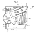
- Figure 1 shows a cutter mechanism according to an embodiment of the present invention.
- the cutter mechanism includes a cutter support 1, a rotating blade support 2, a translating blade support 3 on which a blade 7 is fixed and a clamp 8.
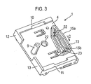
- Figure 3 shows the cutter support 1 in more detail.
- a guide track 15 is provided on the base 4 of the cutter support.
- the guide track 15 defines a substantially oval path between two walls 15a and 15b.
- the guide track is shown to be substantially oval in figure 3 in other embodiments of the invention the guide track may define a predetermined path of any other shape.
- a support member 9 extends perpendicularly from the base 4 of the cutter support.
- the cutter support 1 further comprises end panels 12 and 13, side panels 10 and 11.
- a hole 22 is also provided in the base 4 of the cutter support 1.
- the clamp 8 is located between the cutter support 1 and the rotating blade support 2.
- the clamp 8 is shown in more detail in Figure 14.
- Figure 14 shows the side of the clamp 8 that is positioned against the base 4 of the cutter support 1.
- the clamp 8 comprises a clamping face 24 and two spring receiving recesses 5a and 6a located at the opposite end of the clamp to the clamping face 24.
- the clamp has a cut out section 29, which exposes the guide track 15 when the clamp is attached to the cutter support 1.
- the clamp further comprises an elliptical sleeve 44 through which the support member 9 may protrude when the clamp is connected to the cutter support 1.
- the clamp 8 is slideably connected to the cutter support 1 between the two opposing side panels 10 and 11 of the cutter support 1.
- the clamp 8 is resiliently connected to the cutter support by two springs 5 and 6 that are located in the spring receiving recesses 5a and 6a and act upon the end panels 12 and 13 of the cutter support 1.
- the rotating blade support 2 shown in more detail in Figure 9 , comprises a cylindrical sleeve 34 in which support member 9 of the cutter support is received such that the rotating blade support 2 is pivotally mounted on the cutter support 1.
- a projecting arm 14 of the rotating blade support 2 extends substantially radially from the support member 9 in the plane in which the rotating blade support 2 pivots about the support member 9.
- the translating blade support 3 is shown from a top elevation in Figure 10a and from a bottom elevation in Figure 10b .
- the translating blade support 3 is slideably connected to the projecting arm 14 of the rotating blade support 2 by flanges 37 and 38 that correspond with a recess 17 which extends along the length of the projecting arm 14.
- the projecting arm 14 of the rotating blade support 2 includes a substantially rectangular shaped slot 36 ( Figure 9 ) through which a pin 28 of the translating blade support 3 engages with the guide track 15 located on the cutter support 1.
- FIG 2 shows a view of the cutter mechanism with the rotating blade support 2 removed.
- the clamp 8 includes a cut out section 29 exposing the guide track 15 and a cutter arm 16.
- the cutter arm 16 is shown in more detail in Figure 8 .
- the cutter arm 16 comprises an elongated body 16a which is mounted at one end on spindle 20.
- a pin 21 is mounted at the opposite end of the body 16a from the spindle 20.
- the pin 21 extends perpendicular to the plane of rotation of the cutter arm 16 about the spindle 20.
- the spindle 20 extends through the hole 22 ( Figure 3 ) in the cutter support 1 so that the cutter arm 16 can be rotated in the direction 'A' by the motor 97 ( Figure 12 ).
- the pin 21 may act against the inside edge of a region of the cut out section of the clamp 8.
- the pin 21 of the cutter arm 16 also projects into a narrow slot 32 ( figure 9 ) in the rotating blade support 2 which extends towards the projecting arm 14 of the rotating blade support, such that when the pin 21 rotates about the spindle 20 the rotating blade support 2 is caused to reciprocate along an arc.
- Figure 3 shows the cutter support 1.
- the pin 28 attached to the translating blade support 3 is arranged to follow the path defined by the guide track 15.
- the predetermined path defined by the guide track is a closed loop path. Therefore the pin attached is arranged to follow the path in one direction, for example a clockwise direction indicated by arrow C.
- the predetermined path may be a single path having two ends that the pin 28 must reciprocate between in order to for the translating blade support to move through a complete cutting cycle.
- Two stepped edges 22 and 23 are provided along at the points in the path.
- the purpose of the stepped edges 22 and 23 is to prevent the pin 28 from moving in an anti clockwise direction when changing direction at the extremes of the oval path of the guide track 15.
- the cutting mechanism is orientated relative to the image receiving tape 40 such that the clamping face 24 of the clamp 8 extends across the width of the tape at the cutting zone 59.
- the clamp is held in a retracted position against springs 5 and 6, away from the tape.
- the clamp is held in the retracted position when the cutter arm 16 is in the home position as shown in Figure 2 .
- the pin 21 of the cutter arm 16 abuts against the end of an arc 30 section in the cut out portion of the clamp 8 as shown.
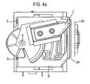
- Figure 4a shows the position of the blade relative to the tape 40 when the cutter arm is in the home position. As shown the clamp 8 and blade 7 are retracted away from the tape. The position of the rotating blade support is controlled by the position of arm 21 of the cutter arm 16 in slot 32 of the rotating blade.
- Figure 4b shows the corresponding position of the pin 21 within the slot 32 of the rotating blade support when the cutter arm 16 is in the home position.
- Figure 4b also shows the path of motion 26 of the pin 21 and the path of motion 27 of the slot 32.
- the position of the rotating blade support 2 controls the position of the pin 28 ( figure 10 ), which projects from the translating blade support 3, in the guide track 15.
- Figure 4c shows the corresponding position of the pin 28 in the guide track 15 when the cutter arm is in the home position.
- the motor 97 is controlled by the processor 200 to drive the spindle 20 of the cutter arm in the direction 'A' shown in figure 8 such that the pin 21 of the cutter arm disengages with the arc 30 of the cut out section 29 in the clamp 8.
- the clamp is biased towards the tape by springs 5 and 6.
- the clamp face 24 clamps the tape onto the housing of the cassette.
- the clamp may be arranged to clamp the tape onto the housing of the printer or any other surface fixed relative to the body of the printer.
- Figure 5a shows the position of the blade relative to the tape 40 when the cutter arm 16 is rotated clockwise from the home position. In this position the clamp 8 is positioned against the tape 40 and the blade 7 and translating blade support are above the tape 40.
- Figure 5b shows the corresponding position of the pin 21 within the slot 32 of the rotating blade support 2 when the cutter arm is rotated clockwise from the home position. As shown, when the rotating blade support is at the upper position the slot is at one end of the path of motion 27.
- Figure 5c shows the corresponding position of the pin 28 in the guide track 15 when the rotating blade support is in the upper position.
- the translating blade support 3 which holds the blade will be partially extended from the arm 14 of the rotating blade support 2 to which it is slideaby connected.
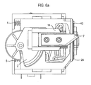
- Figure 6a shows the position of the blade relative to the tape 40 when the cutter arm is rotated clockwise from the position shown in Figure 5a . In this position the clamp 8 remains against the tape 40 and the blade 7 is midway through cutting the tape 40.
- Figure 6b shows the corresponding position of the pin 21 within the slot 32 of the rotating blade support when the cutter arm is rotated clockwise from the position shown in Figure 5b . As shown the rotating blade support is between the two extremes of the path 27 followed by the slot 32.
- Figure 6c shows the corresponding position of the pin 28 in the guide track 15 when the rotating blade support is midway through the cutting position.
- the translating blade support 3 which holds the blade 7 will be partially extended from the arm 14 of the rotating blade support 2 to which it is slideaby connected.
- the distance from the pivot 9 to the position of the pin 28 on the path in Fig 5c is greater than the distance from the pivot 9 to the position of the pin 28 on the path in Figure 6c .
- This causes the translating blade support to be retracted slightly when the rotating blade support 2 moves from the upper position as shown in figure 5 to the mid cutting position as shown in figure 6 .
- Figure 7a shows the position of the blade relative to the tape 40 when the cutter arm is rotated clockwise from the position of the cutter arm in Figure 6a . In this position the clamp 8 remains against the tape 40 and the blade 7 has completed cutting the tape 40.
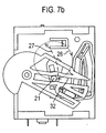
- Figure 7b shows the corresponding position of the pin 21 within the slot 32 of the rotating blade support 2 when the cutter arm is rotated clockwise from the position of the cutter arm shown in Figure 6b . As shown the rotating blade support is at the furthest point in the path 27.
- Figure 7c shows the corresponding position of the pin 28 in the guide track 15 when the rotating blade support is at the lowest point in its path of motion.
- the translating blade support 3 which holds the blade 7 will be retracted further along the arm 14 of the rotating blade support 2 to which it is slideaby connected.
- the motor continues to rotate the spindle 20 until the cutter arm 16 returns to the home position as shown in figures 2 and 4b .
- the arm 21 of the cutter arm 16 abuts against the arc 30 of the cut out section 29 of clamp 8.
- the cutter arm retracts the clamp away from the tape and moves the rotating blade support to the position as shown in Figure 4a .
- the home position of the cutter arm 16 may be detected by a switch 60.
- Figure 15 shows a plunger switch 60 that may be used to detect the home position of the cutter arm 16.
- the plunger switch 60 includes a sloped plunger 57.
- the switch 60 may be attached to the cutter support 1 at a location, as shown in Figure 7c , that causes the plunger 57 to be depressed when the cutter arm returns to the home position.
- a signal is sent from the switch 60 to the microprocessor chip 200 to indicate that the cutter arm has returned to the home position and that the cutting cycle is complete.
- the microprocessor controls the motor 97 to stop the rotation of the cutter arm 16.
- the blade is arranged to move along the width of the tape 40.
- any force exerted by cutting the tape when blade moves though the cutting cycle shown in Figures 4 to 7 is directed toward the base of the cassette receiving bay 102. As such the force caused by cutting the tape will not displace the position of the tape.
- the translating blade support 3 is extended from the projecting arm 14 of the rotating blade support 2. In this extended position the lateral support provided for the blade, which is perpendicular to the plane of the blade, is limited.
- the blade may be supported on one side by the edge of the clamping face 24 of the clamp 8 as shown in Figure 1 .
- the support provided by the clamping face 24 in the embodiment shown in Figure 1 will however not prevent the blade from moving away from the edge of the clamping face during the cutting cycle.
- the lateral movement of the blade 7 may also be restricted by a slot 150 located in the housing of the tape cassette as shown in Figure 2 .
- the purpose of the slot 150 in the housing of the tape cassette is to accommodate the blade 7 during a cutting cycle, the dimensions of the slot 150 in the cassette are not suited to providing lateral support to the blade during the cutting cycle, especially when the tape cassette is designed for use in more than one type of printer.
- the clamp 8 is arranged to prevent the tape from distorting and to provide lateral support on both sides of the blade when the blade is in contact with the tape.
- a slot 151 is provided in the clamping face 24 of the claim 8.
- the slot 151 in the clamping face 24 of the clamp 8 is arranged to receive the blade 7, such that during the cutting cycle the blade 7 will extend through the slot to contact the tape.
- the blade may only extend through the slot 151 when the translating blade support member 3 is extended and the blade is in the cutting position.
- the blade may also be arranged to extend into the slot when the blade is retracted and the rotating blade support is in the home position. This arrangement will prevent the blade from jamming behind the clamping face. In order to prevent the blade from jamming it is not necessary for the blade to extend through the slot. Instead it is sufficient for the blade to project into the slot such that the blade 7 is supported by an internal wall of the slot 151.
- the clamping face 24 of the clamp 8 is arranged to clamp the tape on either side of the blade 7 while the tape is being cut by the blade, this prevents the tape from distorting during the cutting operation.
- a further advantage of clamping the tape on either side of the blade is that the clamp provides lateral support on both sides of the blade. This ensures that the cut surface of the tape is straight.
- a further advantage to clamping the tape on either side of the blade is that the tape is held in place on either side of the blade while the tape is being cut.
- embodiments of the present invention may also be applied to other printers, such as laser printers, PC printers and stand alone printers, having a cutting mechanism that is used to cut off the image receiving medium.
- Printers embodying the present invention may be capable of monochrome printing, grayscale printing or full colour printing.
Description
- The present invention relates to a printing apparatus and to a method of cutting an image receiving medium. In particular, the present invention relates to a tape printing apparatus having a cutter arranged to cut the tape, so that the tape forms a label.
- Tape printers are known which use a supply of tape, housed in a cassette received in the tape printer. The tape comprises an image receiving layer and a backing layer which are secured to one another via an adhesive layer. After an image has been printed onto the image receiving layer, the backing layer can be removed allowing the image receiving layer to be secured to an object using the adhesive layer. Such tape printers include a cutting mechanism for cutting off a portion of the tape after an image has been printed onto the image receiving layer so that the portion of tape can be used as a label. For this purpose the cutting mechanism includes a blade which is intended to cut through all the layers of the tape.
- The cutting mechanism in these known tape printers can be operated by the user manually. Alternatively the cutting mechanism may be driven by a motor in the tape printer. Some examples of automatic cutting mechanisms are described in
EP-A-534799 EP-A-929402 EP-A-764542 US-A-5599119 . An embodiment of an automatic cutter is incorporated into the DYMO PC-10 Electronic Labelmaker. - A relatively large force needs to be applied by the blade on the tape in order to perform the cutting operation. Over time, continual cutting operations cause the blade to wear. This is disadvantageous since it is not desirable for a user of the printer to change the blade during the lifetime of the printer. Furthermore the force required to cut the tape can often distort the tape and in some cases cause the tape to move during the cutting operation. As the blade wears the tape is more likely to distort during the cutting operation. Distortion of the tape during cutting may result in a label having a cut edge that is not smooth.
- The force required to cut the tape may also cause the position of a tape cassette housing the tape to displace during cutting. This causes further problems such as incomplete cutting of the tape, and misalignment of the printed image on the tape in subsequent printing operations.
- It is therefore an aim of the present invention to overcome the disadvantages discussed above.
-
EP 0711637 A1 describes a manual printing mechanism wherein an actuating member is driven by an anvil to cut through a tape. A spring is used to return the anvil and actuating member to a start position. -
EP 0798254 A2 describes a device for cutting, cutting off or perforating of paper, pasteboard or the like consisting of a cutting tool led within a framework. - According to a first aspect of the present invention there is provided a printer for printing an image on an image receiving medium comprising: a tape receiving portion for receiving a supply of image receiving medium on which an image is to be printed; a printing mechanism arranged to print an image on said medium; and a cutting mechanism for cutting off a portion of said medium, wherein the cutting mechanism comprises a cutter guide track defining a predetermined path for guiding a cutter of the cutting mechanism during a cutting cycle, wherein during a first portion of the cutting cycle the guide track is arranged to guide the cutter to intersect a plane of the medium such that a portion of the medium is cut off, and wherein during a second portion of the cycle the guide track is arranged to guide the cutter to return to a home position such that the cutter does not intersect the plane of the medium.
- According to a second aspect of the present invention there is provided a method of cutting an image receiving medium to form a label comprising; guiding a cutter to move along a predetermined path during a cutting cycle, wherein during a first portion of the cutting cycle the guide track is arranged to guide the cutter to intersect a plane of the medium such that a portion of the medium is cut off, and wherein during a second portion of the cycle the guide track is arranged to guide the cutter to return to a home position such that the cutter does not intersect the plane of the medium.
- For a better understanding of the present invention and to show how the same may be carried into effect reference will now be made by way of example to the accompanying drawings in which:
-
Figure 1 shows a cutter mechanism in accordance with an embodiment of the present invention; -
Figure 2 shows a cutter mechanism in accordance with an embodiment of the present invention; -
Figure 3 shows a cutter support of the cutter mechanism in accordance with an embodiment of the present invention; -
Figure 4a shows the position of a blade of the cutter mechanism in relation to the tape in accordance with an embodiment of the present invention; -
Figure 4b shows the position of a cutter arm of the cutter mechanism during cutting in accordance with an embodiment of the present invention; -
Figure 4c shows the position of a pin in a guide track of the cutter mechanism in accordance with an embodiment of the present invention; -
Figure 5a shows the position of a blade of the cutter mechanism in relation to the tape in accordance with an embodiment of the present invention; -
Figure 5b shows the position of a cutter arm of the cutter mechanism during cutting in accordance with an embodiment of the present invention; -
Figure 5c shows the position of a pin in a guide track of the cutter mechanism in accordance with an embodiment of the present invention; -
Figure 6a shows the position of a blade of the cutter mechanism in relation to the tape in accordance with an embodiment of the present invention; -
Figure 6b shows the position of a cutter arm of the cutter mechanism during cutting in accordance with an embodiment of the present invention; -
Figure 6c shows the position of a pin in a guide track of the cutter mechanism in accordance with an embodiment of the present invention; -
Figure 7a shows the position of a blade of the cutter mechanism in relation to the tape in accordance with an embodiment of the present invention; -
Figure 7b shows the position of a cutter arm of the cutter mechanism during cutting in accordance with an embodiment of the present invention; -
Figure 7c shows the position of a pin in a guide track of the cutter mechanism in accordance with an embodiment of the present invention; -
Figure 8 shows a cutter arm of the cutter mechanism in accordance with an embodiment of the present invention; -
Figure 9 shows a rotating blade support of the cutter mechanism in accordance with an embodiment of the present invention; -
Figure 10 shows a translating blade support of the cutter mechanism in accordance with an embodiment of the present invention; -
Figure 11 shows a tape printer in accordance with an embodiment of the present invention; -
Figure 12 shows the basic circuitry for controlling a tape printer in accordance with an embodiment of the present invention; -
Figure 13 shows a cassette receiving bay of the tape printer in accordance with an embodiment of the present invention; -
Figure 14 shows a clamp of the cutter mechanism in accordance with an embodiment of the present invention; -
Figure 15 shows a switch used to detect the home position of the cutter arm in accordance with an embodiment of the present invention; -
Figure 16 shows the clamp of the cutter mechanism in accordance with a further embodiment of the present invention; -
Figure 17 shows the cutter mechanism in accordance with a further embodiment of the present invention; -
Figure 18 shows the distortion of the tape during a cutting operation. -
Figure 11 shows a schematic diagram of atape printing apparatus 100 according to an embodiment of the present invention. The tape printing apparatus comprises akeyboard 101 and acassette receiving bay 102. - The
cassette receiving bay 102 houses a cassette containing image receiving tape on which a label is printed. The image receiving tape has an image receiving layer for receiving the image and an adhesive layer for allowing the label to be adhered to a surface. - The keyboard has a plurality of
data entry keys 103 such as numbered, lettered and punctuation keys for inputting data to be printed as a label and function keys for editing the input data. The keyboard may also have aprint key 104 which is operated when it is desired that a label be printed. Additionally an on/offkey 105 is also provided for switching the tape printing apparatus on and off. - The tape printing apparatus has a liquid crystal display (LCD) 106 which displays the data as it is entered. The display allows the user to view all or part of the label to be printed which facilitates the editing of the label prior to its printing. Additionally, the display is driven by a display driver (not shown).
- Basic circuitry for controlling the
tape printing device 100 is shown inFigure 12 . There is amicroprocessor chip 200 having a read only memory (ROM) 202, amicroprocessor 201 and random access memory capacity indicated diagrammatically byRAM 204. Themicroprocessor chip 200 is connected to receive label data input to it from a data input device such as thekeyboard 101. Themicroprocessor chip 200 outputs data to drive thedisplay 106 via adisplay driver chip 209 to display a label to be printed (or a part thereof) and/or a message for the user. The display driver alternatively may form part of the microprocessor chip. Additionally, themicroprocessor chip 200 also outputs data to drive aprint head 206 so that the label data is printed onto the image receiving tape to form a label. Themicroprocessor chip 200 also controls amotor 207 for driving the tape. Finally themicroprocessor chip 100 also controls amotor 97 for operating acutting mechanism 58 to allow a length of tape to be cut off. The manner in which the cutting mechanism is controlled will be discussed hereinafter. - In one embodiment of the invention the
tape printer 100 may be arranged print to an image on an image receiving tape using an ink ribbon. This method of printing is known as thermal transfer printing.Figure 13 shows a schematic diagram of acassette receiving bay 102 in thetape printing apparatus 100 arranged to print by thermal transfer. In this embodiment anink ribbon cassette 52 containing an ink ribbon 45 is installed together with an image receivingtape cassette 50 in thecassette receiving bay 102. The image receivingtape cassette 50 contains a supply ofimage receiving tape 40 provided on asupply spool 88. - The
cassette bay 102 also accommodates at least onethermal print head 206 and aplaten 80 which cooperate to define a print zone 53. Theprint head 206 is able to pivot about a pivot point 54 so that it can be brought into contact with theplaten 80 for printing and moved away from theplaten 80 to enable thecassette 50 to be removed and replaced. In the operative position, in one embodiment of the invention theplaten 80 is rotated by a motor 207 (Figure 12 ) to cause thetape 40 to be driven past theprint head 206 to the cuttingzone 59. - The ink ribbon 45 passes through the print zone together with the
image receiving tape 40. According to this embodiment of the invention theimage receiving tape 40 is an ink receiving tape. - In an alternative embodiment of the invention the
image receiving tape 40 is a direct thermal material. In this embodiment of the invention theprint head 206 produces an image on the tape by applying heat directly to thetape 40. Accordingly when the image receivingtape cassette 50 includes directthermal tape 40 there is no need to provide anink ribbon cassette 52 in thecassette receiving bay 102 of theprinter 100. - In one embodiment of the invention the image receiving tape may comprise a continuous image receiving layer. In an alternative embodiment of the present invention the image receiving tape may comprise die cut labels.
- Reference is now made to
Figure 1. Figure 1 shows a cutter mechanism according to an embodiment of the present invention. The cutter mechanism includes acutter support 1, arotating blade support 2, a translatingblade support 3 on which ablade 7 is fixed and aclamp 8. -
Figure 3 shows thecutter support 1 in more detail. Aguide track 15 is provided on thebase 4 of the cutter support. Theguide track 15 defines a substantially oval path between twowalls figure 3 in other embodiments of the invention the guide track may define a predetermined path of any other shape. - A
support member 9 extends perpendicularly from thebase 4 of the cutter support. Thecutter support 1 further comprisesend panels side panels hole 22 is also provided in thebase 4 of thecutter support 1. - As shown in
Figure 1 theclamp 8 is located between thecutter support 1 and therotating blade support 2. Theclamp 8 is shown in more detail inFigure 14. Figure 14 shows the side of theclamp 8 that is positioned against thebase 4 of thecutter support 1. Theclamp 8 comprises a clampingface 24 and two spring receiving recesses 5a and 6a located at the opposite end of the clamp to the clampingface 24. The clamp has a cut outsection 29, which exposes theguide track 15 when the clamp is attached to thecutter support 1. The clamp further comprises anelliptical sleeve 44 through which thesupport member 9 may protrude when the clamp is connected to thecutter support 1. - The
clamp 8 is slideably connected to thecutter support 1 between the two opposingside panels cutter support 1. Theclamp 8 is resiliently connected to the cutter support by twosprings end panels cutter support 1. - The
rotating blade support 2, shown in more detail inFigure 9 , comprises acylindrical sleeve 34 in whichsupport member 9 of the cutter support is received such that therotating blade support 2 is pivotally mounted on thecutter support 1. A projectingarm 14 of therotating blade support 2 extends substantially radially from thesupport member 9 in the plane in which therotating blade support 2 pivots about thesupport member 9. - The translating
blade support 3 is shown from a top elevation inFigure 10a and from a bottom elevation inFigure 10b . The translatingblade support 3 is slideably connected to the projectingarm 14 of therotating blade support 2 byflanges recess 17 which extends along the length of the projectingarm 14. The projectingarm 14 of therotating blade support 2 includes a substantially rectangular shaped slot 36 (Figure 9 ) through which apin 28 of the translatingblade support 3 engages with theguide track 15 located on thecutter support 1. -
Figure 2 shows a view of the cutter mechanism with therotating blade support 2 removed. As shown theclamp 8 includes a cut outsection 29 exposing theguide track 15 and acutter arm 16. Thecutter arm 16 is shown in more detail inFigure 8 . Thecutter arm 16 comprises anelongated body 16a which is mounted at one end onspindle 20. Apin 21 is mounted at the opposite end of thebody 16a from thespindle 20. Thepin 21 extends perpendicular to the plane of rotation of thecutter arm 16 about thespindle 20. Thespindle 20 extends through the hole 22 (Figure 3 ) in thecutter support 1 so that thecutter arm 16 can be rotated in the direction 'A' by the motor 97 (Figure 12 ). - The
pin 21 may act against the inside edge of a region of the cut out section of theclamp 8. Thepin 21 of thecutter arm 16 also projects into a narrow slot 32 (figure 9 ) in therotating blade support 2 which extends towards the projectingarm 14 of the rotating blade support, such that when thepin 21 rotates about thespindle 20 therotating blade support 2 is caused to reciprocate along an arc. - Reference is again made to
Figure 3 which shows thecutter support 1. In operation thepin 28 attached to the translatingblade support 3 is arranged to follow the path defined by theguide track 15. In the embodiment described the predetermined path defined by the guide track is a closed loop path. Therefore the pin attached is arranged to follow the path in one direction, for example a clockwise direction indicated by arrow C. - Alternatively the predetermined path may be a single path having two ends that the
pin 28 must reciprocate between in order to for the translating blade support to move through a complete cutting cycle. - Two stepped
edges pin 28 from moving in an anti clockwise direction when changing direction at the extremes of the oval path of theguide track 15. - As shown in
Figure 2 , the cutting mechanism is orientated relative to theimage receiving tape 40 such that the clampingface 24 of theclamp 8 extends across the width of the tape at the cuttingzone 59. - During printing the clamp is held in a retracted position against
springs cutter arm 16 is in the home position as shown inFigure 2 . When the cutter arm is in the home position thepin 21 of thecutter arm 16 abuts against the end of anarc 30 section in the cut out portion of theclamp 8 as shown. - The operation of the cutting mechanism according to an embodiment of the invention will now be described with reference to
figures 4 ,5 ,6 and7 . -
Figure 4a shows the position of the blade relative to thetape 40 when the cutter arm is in the home position. As shown theclamp 8 andblade 7 are retracted away from the tape. The position of the rotating blade support is controlled by the position ofarm 21 of thecutter arm 16 inslot 32 of the rotating blade. -
Figure 4b shows the corresponding position of thepin 21 within theslot 32 of the rotating blade support when thecutter arm 16 is in the home position.Figure 4b also shows the path ofmotion 26 of thepin 21 and the path ofmotion 27 of theslot 32. - The position of the
rotating blade support 2 controls the position of the pin 28 (figure 10 ), which projects from the translatingblade support 3, in theguide track 15.Figure 4c shows the corresponding position of thepin 28 in theguide track 15 when the cutter arm is in the home position. When the pin is at the position shown inFigure 4c the translating blade support which holds the blade will be completely retracted within thearm 14 of therotating blade support 2. - When a cutting operation is initiated by the
processor 200, themotor 97 is controlled by theprocessor 200 to drive thespindle 20 of the cutter arm in the direction 'A' shown infigure 8 such that thepin 21 of the cutter arm disengages with thearc 30 of the cut outsection 29 in theclamp 8. The clamp is biased towards the tape bysprings arc 30, the clamp is forced towards thetape 40. The clamp face 24 clamps the tape onto the housing of the cassette. In an alternative embodiment of the invention the clamp may be arranged to clamp the tape onto the housing of the printer or any other surface fixed relative to the body of the printer. -
Figure 5a shows the position of the blade relative to thetape 40 when thecutter arm 16 is rotated clockwise from the home position. In this position theclamp 8 is positioned against thetape 40 and theblade 7 and translating blade support are above thetape 40. -
Figure 5b shows the corresponding position of thepin 21 within theslot 32 of therotating blade support 2 when the cutter arm is rotated clockwise from the home position. As shown, when the rotating blade support is at the upper position the slot is at one end of the path ofmotion 27. -
Figure 5c shows the corresponding position of thepin 28 in theguide track 15 when the rotating blade support is in the upper position. When thepin 28 is at the position shown inFigure 5c the translatingblade support 3 which holds the blade will be partially extended from thearm 14 of therotating blade support 2 to which it is slideaby connected. -
Figure 6a shows the position of the blade relative to thetape 40 when the cutter arm is rotated clockwise from the position shown inFigure 5a . In this position theclamp 8 remains against thetape 40 and theblade 7 is midway through cutting thetape 40. -
Figure 6b shows the corresponding position of thepin 21 within theslot 32 of the rotating blade support when the cutter arm is rotated clockwise from the position shown inFigure 5b . As shown the rotating blade support is between the two extremes of thepath 27 followed by theslot 32. -
Figure 6c shows the corresponding position of thepin 28 in theguide track 15 when the rotating blade support is midway through the cutting position. When the pin is at the position shown inFigure 6c the translatingblade support 3 which holds theblade 7 will be partially extended from thearm 14 of therotating blade support 2 to which it is slideaby connected. In one embodiment of the invention the distance from thepivot 9 to the position of thepin 28 on the path inFig 5c is greater than the distance from thepivot 9 to the position of thepin 28 on the path inFigure 6c . This causes the translating blade support to be retracted slightly when therotating blade support 2 moves from the upper position as shown infigure 5 to the mid cutting position as shown infigure 6 . This advantageously causes different points along the blade to intersect the tape as the blade transverses and cuts the tape. This prevents excessive wear on one point on theblade 7. This also prevents a build up of adhesive on the blade when cutting the adhesive layer of the tape. -
Figure 7a shows the position of the blade relative to thetape 40 when the cutter arm is rotated clockwise from the position of the cutter arm inFigure 6a . In this position theclamp 8 remains against thetape 40 and theblade 7 has completed cutting thetape 40. -
Figure 7b shows the corresponding position of thepin 21 within theslot 32 of therotating blade support 2 when the cutter arm is rotated clockwise from the position of the cutter arm shown inFigure 6b . As shown the rotating blade support is at the furthest point in thepath 27. -
Figure 7c shows the corresponding position of thepin 28 in theguide track 15 when the rotating blade support is at the lowest point in its path of motion. When the pin is at the position shown inFigure 7c the translatingblade support 3 which holds theblade 7 will be retracted further along thearm 14 of therotating blade support 2 to which it is slideaby connected. - The motor continues to rotate the
spindle 20 until thecutter arm 16 returns to the home position as shown infigures 2 and4b . As the cutter arm rotates towards the home position thearm 21 of thecutter arm 16 abuts against thearc 30 of the cut outsection 29 ofclamp 8. The cutter arm retracts the clamp away from the tape and moves the rotating blade support to the position as shown inFigure 4a . - When the rotating blade support moves upwards towards the home position the
pin 28 connected to the translatingblade support 2 continues to follow the guide track back to the position as shown infigure 4c . Since the distance between this portion of the path followed by the pin during the upward movement of the blade and thepivot 9 is less than the distance between the portion of the path followed by the pin during the downward movement of the blade and thepivot 9, the blade is retracted when the rotating blade support returns to the home position. Accordingly when the rotating blade support returns to the home position the blade is retracted along thearm 14 and held away from thetape 40. - According to an embodiment of the invention, the home position of the
cutter arm 16 may be detected by aswitch 60.Figure 15 shows aplunger switch 60 that may be used to detect the home position of thecutter arm 16. Theplunger switch 60 includes a slopedplunger 57. Theswitch 60 may be attached to thecutter support 1 at a location, as shown inFigure 7c , that causes theplunger 57 to be depressed when the cutter arm returns to the home position. When theplunger 57 is depressed a signal is sent from theswitch 60 to themicroprocessor chip 200 to indicate that the cutter arm has returned to the home position and that the cutting cycle is complete. In response to the signal received from theswitch 60 the microprocessor controls themotor 97 to stop the rotation of thecutter arm 16. - In a preferred embodiment of the invention the blade is arranged to move along the width of the
tape 40. - When the cutting mechanism is orientated relative to the tape as shown in
Figure 2 , any force exerted by cutting the tape when blade moves though the cutting cycle shown inFigures 4 to 7 is directed toward the base of thecassette receiving bay 102. As such the force caused by cutting the tape will not displace the position of the tape. - A further embodiment of the invention will now be described with reference to
Figures 16 and17 . - During a cutting cycle, when the
blade 7 is in contact with the tape, the translatingblade support 3 is extended from the projectingarm 14 of therotating blade support 2. In this extended position the lateral support provided for the blade, which is perpendicular to the plane of the blade, is limited. - When the
blade 7 is in contact with the tape, the interaction of theblade 7 and the tape causes a force to act on the tape. This causes thetape 40 to distort as shown inFigure 18 . This is particularly pronounced when a projection of thetape cassette 50 supports the bottom edge of the tape. - Similarly when the blade interacts with the tape a force also acts on the blade. Without lateral support to guide the path of the blade during the cutting cycle, the path of motion of the blade will be offset by the resistance provided by the tape, thus causing an irregular cut surface that is not straight and smooth.
- In the embodiments of the invention described thus far, the blade may be supported on one side by the edge of the clamping
face 24 of theclamp 8 as shown inFigure 1 . The support provided by the clampingface 24 in the embodiment shown inFigure 1 will however not prevent the blade from moving away from the edge of the clamping face during the cutting cycle. - Also, the lateral movement of the
blade 7 may also be restricted by aslot 150 located in the housing of the tape cassette as shown inFigure 2 . However, since the purpose of theslot 150 in the housing of the tape cassette is to accommodate theblade 7 during a cutting cycle, the dimensions of theslot 150 in the cassette are not suited to providing lateral support to the blade during the cutting cycle, especially when the tape cassette is designed for use in more than one type of printer. - According to an embodiment of the invention that is provided to solve this problem, the
clamp 8 is arranged to prevent the tape from distorting and to provide lateral support on both sides of the blade when the blade is in contact with the tape. - As shown in
Figure 16 aslot 151 is provided in the clampingface 24 of theclaim 8. - Referring now to
Figure 17 , theslot 151 in the clampingface 24 of theclamp 8 is arranged to receive theblade 7, such that during the cutting cycle theblade 7 will extend through the slot to contact the tape. - In one embodiment of the invention the blade may only extend through the
slot 151 when the translatingblade support member 3 is extended and the blade is in the cutting position. - In a preferred embodiment of the invention the blade may also be arranged to extend into the slot when the blade is retracted and the rotating blade support is in the home position. This arrangement will prevent the blade from jamming behind the clamping face. In order to prevent the blade from jamming it is not necessary for the blade to extend through the slot. Instead it is sufficient for the blade to project into the slot such that the
blade 7 is supported by an internal wall of theslot 151. - As the clamping
face 24 of theclamp 8 is arranged to clamp the tape on either side of theblade 7 while the tape is being cut by the blade, this prevents the tape from distorting during the cutting operation. - A further advantage of clamping the tape on either side of the blade is that the clamp provides lateral support on both sides of the blade. This ensures that the cut surface of the tape is straight.
- A further advantage to clamping the tape on either side of the blade is that the tape is held in place on either side of the blade while the tape is being cut.
- Whilst the embodiments of the present invention have been described in relation to tape printers, embodiments of the present invention may also be applied to other printers, such as laser printers, PC printers and stand alone printers, having a cutting mechanism that is used to cut off the image receiving medium.
- Printers embodying the present invention may be capable of monochrome printing, grayscale printing or full colour printing.
- In view of the foregoing description it will be evident to a person skilled in the art that various modifications may be made within the scope of the invention as claimed.
Claims (22)
- A printer (100) for printing an image on an image receiving medium (40) comprising:a tape receiving portion for receiving a supply of image receiving medium on which an image is to be printed;a printing mechanism (53, 80, 206) arranged to print an image on said medium; anda cutting mechanism (58) for cutting off a portion of said medium, wherein the cutting mechanism comprises a cutter guide track (15) defining a predetermined path for guiding a cutter (7) of the cutting mechanism (58) during a cutting cycle, wherein during a first portion of the cutting cycle the guide track (15) is arranged to guide the cutter to intersect a plane of the medium such that a portion of the medium is cut off, and characterized
wherein during a second portion of the cycle the guide track (15) is arranged to guide the cutter to return to a home position such that the cutter does not intersect the plane of the medium. - The printer (100) of claim 1 wherein different parts of the cutter (7) intersect the medium (40) as the cutter moves to cut off said portion.
- A printer (100) as claimed in any preceding claim further comprising; a cutter support (2,3) arranged to support the cutter (7).
- A printer (100) as claimed in claim 3 wherein the cutter (7) is arranged to move along at least one plane relative to the cutter support (2,3).
- A printer (100) as claimed in claim 3 or 4 wherein the cutter support (2,3) is arranged to pivot in an arc about an axis that is fixed relative the tape printer housing.
- A printer (100) as claimed in claim 5 further comprising;
driving means (207) for driving the cutter support (2,3) to pivot in the arc about the fixed axis. - A printer (100) as claimed in any preceding claim wherein the cutter (7) comprises an engagement means (28) for engaging the cutter with the guide track (15).
- A printer (100) as claimed in claim 7 when dependent on claims 3 to 7, wherein during the first portion of the cutting cycle the engagement means (28) is arranged to pivot about the axis at a first radius and wherein during the second cycle the engagement means is arranged to pivot about the axis at a second radius, such that the first radius is greater than the second radius.
- A printer (100) as claimed in claims 3 to 8 wherein the printer further includes clamping means (8) for clamping the image receiving medium (40) when the cutter (7) is located in the first portion of the cutting cycle.
- A printer (100) as claimed in claim 9 wherein the clamping means (8) is arranged to clamp the medium (4) at opposite sides of a cutting plane of the cutter (7).
- A printer (100) as claimed in claim 9 or 10 wherein the clamping means (8) comprises a slot (151) through which the cutter (7) extends during the first portion of the cutting cycle.
- A printer (100) as claimed in claims 9 to 11 when claim 9 is dependent on claim 6 wherein the driving means (207) is further arranged to drive the clamping means (8) to release the image receiving medium (40).
- A printer (100) as claimed in any preceding claim wherein the medium (40) is a tape.
- A printer (100) as claimed in claims 1 to 12 wherein the medium (40) comprises die cut labels.
- A printer (100) as claimed in any preceding claim wherein the printer is a tape printer.
- A method of cutting an image receiving medium (40) to form a label comprising;
guiding a cutter (7) to move along a predetermined path during a cutting cycle, wherein during a first portion of the cutting cycle the guide track (15) is arranged to guide the cutter (7) to intersect a plane of the medium such that a portion of the medium is cut off, and characterized
wherein during a second portion of the cycle the guide track (15) is arranged to guide the cutter to return to a home position such that the cutter does not intersect the plane of the medium. - A method of claim 16, whereby different parts of the cutter (7) intersect the image receiving medium (40) as the cutter moves as the cutter moves to cut off said portion.
- A method as claimed in claim 16 wherein the cutter (7) pivots about a fixed axis as the cutter is guided to move along the path (15).
- A method as claimed in claims 16 to 18 wherein the method further comprises;
clamping the medium as the cutter (7) moves along the first portion of the cutting cycle. - A method as claimed in claim 19 wherein the step of clamping the medium (40) as the cutter (7) moves along the first portion of the cutting cycle comprises clamping the medium at opposite sides of a cutting plane of the cutter.
- A tape printer as claimed in claim 19 or 20 wherein the cutter (7) extend through a slot (151) provided in the clamp (8) during the first portion of the cutting cycle.
- A method as claimed in claims 19 to 21 wherein the method further comprises;
releasing the medium (40) from the clamp (8) as the cutter (7) moves along the second portion of the cutting cycle.
Priority Applications (8)
| Application Number | Priority Date | Filing Date | Title |
|---|---|---|---|
| EP11154198.3A EP2314457B1 (en) | 2006-12-22 | 2007-10-05 | Printing apparatus |
| US12/091,276 US8517619B1 (en) | 2006-12-22 | 2007-12-20 | Printing apparatus |
| AU2007337831A AU2007337831A1 (en) | 2006-12-22 | 2007-12-20 | Printing apparatus |
| CA2673397A CA2673397C (en) | 2006-12-22 | 2007-12-20 | Printing apparatus |
| RU2009128234/12A RU2009128234A (en) | 2006-12-22 | 2007-12-20 | PRINTING DEVICE |
| CN2007800503282A CN101610910B (en) | 2006-12-22 | 2007-12-20 | Printing apparatus |
| JP2009542274A JP5374756B2 (en) | 2006-12-22 | 2007-12-20 | Printing device |
| PCT/IB2007/004456 WO2008078201A2 (en) | 2006-12-22 | 2007-12-20 | Printing apparatus |
Applications Claiming Priority (1)
| Application Number | Priority Date | Filing Date | Title |
|---|---|---|---|
| GB0625815A GB0625815D0 (en) | 2006-12-22 | 2006-12-22 | Printing apparatus |
Related Child Applications (2)
| Application Number | Title | Priority Date | Filing Date |
|---|---|---|---|
| EP11154198.3A Division EP2314457B1 (en) | 2006-12-22 | 2007-10-05 | Printing apparatus |
| EP11154198.3 Division-Into | 2011-02-11 |
Publications (2)
| Publication Number | Publication Date |
|---|---|
| EP1935656A1 EP1935656A1 (en) | 2008-06-25 |
| EP1935656B1 true EP1935656B1 (en) | 2011-09-21 |
Family
ID=37758978
Family Applications (2)
| Application Number | Title | Priority Date | Filing Date |
|---|---|---|---|
| EP11154198.3A Active EP2314457B1 (en) | 2006-12-22 | 2007-10-05 | Printing apparatus |
| EP20070253954 Active EP1935656B1 (en) | 2006-12-22 | 2007-10-05 | Printing apparatus |
Family Applications Before (1)
| Application Number | Title | Priority Date | Filing Date |
|---|---|---|---|
| EP11154198.3A Active EP2314457B1 (en) | 2006-12-22 | 2007-10-05 | Printing apparatus |
Country Status (8)
| Country | Link |
|---|---|
| US (1) | US8517619B1 (en) |
| EP (2) | EP2314457B1 (en) |
| JP (1) | JP5374756B2 (en) |
| CN (1) | CN101610910B (en) |
| AU (1) | AU2007337831A1 (en) |
| CA (1) | CA2673397C (en) |
| GB (1) | GB0625815D0 (en) |
| RU (1) | RU2009128234A (en) |
Families Citing this family (4)
| Publication number | Priority date | Publication date | Assignee | Title |
|---|---|---|---|---|
| CN102009415B (en) * | 2010-11-22 | 2012-07-25 | 上海紫华包装有限公司 | Tail shearing device of PET (polyethylene terephthalate) bottle embryo |
| GB2508584B (en) * | 2012-10-15 | 2020-02-26 | Sanford Lp | Printing apparatus |
| CN107379087A (en) * | 2017-09-25 | 2017-11-24 | 北京硕方信息技术有限公司 | A kind of cutting mechanism and apply its printing equipment |
| CN110253665B (en) * | 2019-06-18 | 2021-08-06 | 温州华邦安全封条股份有限公司 | Express delivery packing carton manufacturing installation |
Family Cites Families (15)
| Publication number | Priority date | Publication date | Assignee | Title |
|---|---|---|---|---|
| AT371149B (en) | 1981-10-28 | 1983-06-10 | Ver Edelstahlwerke Ag | REPAIR STEEL AND USE THEREOF |
| JPH0584994A (en) | 1991-09-26 | 1993-04-06 | Brother Ind Ltd | Tape printer |
| CA2107746A1 (en) | 1992-10-06 | 1994-04-07 | Masahiko Nunokawa | Tape printing device and tape cartridge used therein |
| GB9314386D0 (en) | 1993-07-12 | 1993-08-25 | Esselte Dymo Nv | A cassette for a thermal printer |
| GB9517438D0 (en) * | 1994-11-14 | 1995-10-25 | Esselte Dymo Nv | A cutting mechanism |
| US5746527A (en) | 1995-09-19 | 1998-05-05 | Seiko Epson Corporation | Printing apparatus provided with an auto cutter |
| DE19612897A1 (en) * | 1996-03-30 | 1997-10-02 | Ruhlatec Industrieprodukte | Device for optional cutting, cutting or perforating |
| US5971639A (en) * | 1996-11-11 | 1999-10-26 | Samsung Electro-Mechanics Co., Ltd. | Paper cutting apparatus in a small-sized printer |
| JP3658636B2 (en) | 1997-06-11 | 2005-06-08 | カシオ計算機株式会社 | Printing device |
| EP0909651B1 (en) | 1997-10-18 | 2001-07-11 | Esselte N.V. | Tape printer having a cutter with a guide mechanism |
| JP4452392B2 (en) * | 2000-09-29 | 2010-04-21 | セイコーエプソン株式会社 | Tape printer |
| US6347896B1 (en) * | 2000-10-25 | 2002-02-19 | Xac Automation Corporation | Cutting mode switching module in a printer |
| KR100569169B1 (en) * | 2003-02-13 | 2006-04-07 | 세이코 엡슨 가부시키가이샤 | Tape printing apparatus, label producing method, and storage medium |
| EP1650035B1 (en) * | 2004-10-22 | 2011-01-05 | Sanford, L.P. | Hybrid printer |
| JP2008296559A (en) * | 2007-06-04 | 2008-12-11 | Seiko Epson Corp | Tape processor |
-
2006
- 2006-12-22 GB GB0625815A patent/GB0625815D0/en not_active Ceased
-
2007
- 2007-10-05 EP EP11154198.3A patent/EP2314457B1/en active Active
- 2007-10-05 EP EP20070253954 patent/EP1935656B1/en active Active
- 2007-12-20 JP JP2009542274A patent/JP5374756B2/en active Active
- 2007-12-20 CN CN2007800503282A patent/CN101610910B/en active Active
- 2007-12-20 US US12/091,276 patent/US8517619B1/en active Active
- 2007-12-20 AU AU2007337831A patent/AU2007337831A1/en not_active Abandoned
- 2007-12-20 RU RU2009128234/12A patent/RU2009128234A/en not_active Application Discontinuation
- 2007-12-20 CA CA2673397A patent/CA2673397C/en not_active Expired - Fee Related
Also Published As
| Publication number | Publication date |
|---|---|
| GB0625815D0 (en) | 2007-02-07 |
| JP2011502810A (en) | 2011-01-27 |
| JP5374756B2 (en) | 2013-12-25 |
| CN101610910A (en) | 2009-12-23 |
| US8517619B1 (en) | 2013-08-27 |
| RU2009128234A (en) | 2011-01-27 |
| CA2673397A1 (en) | 2008-07-03 |
| CA2673397C (en) | 2015-06-02 |
| EP2314457B1 (en) | 2015-12-23 |
| EP1935656A1 (en) | 2008-06-25 |
| CN101610910B (en) | 2012-01-11 |
| AU2007337831A1 (en) | 2008-07-03 |
| EP2314457A1 (en) | 2011-04-27 |
Similar Documents
| Publication | Publication Date | Title |
|---|---|---|
| EP1674274B1 (en) | Tape printer with tape jam eliminating control in relation to tape cutting operation | |
| JP6011120B2 (en) | Sheet cartridge, label producing apparatus, and label producing apparatus control method | |
| EP1559566B1 (en) | Label printer | |
| JP2006116969A (en) | Hybrid printer | |
| EP1074392A1 (en) | Tape printer | |
| RU2412059C2 (en) | Belt printing device | |
| EP1935656B1 (en) | Printing apparatus | |
| EP1066975B1 (en) | Printer with variable platen pressure | |
| JP3959055B2 (en) | Cutter unit and tape printer | |
| JP2003146493A (en) | Roll paper hold device and printer | |
| WO2008078201A2 (en) | Printing apparatus | |
| JP5516779B2 (en) | Half-cut device and tape printer | |
| US7077587B2 (en) | Tape printing apparatus with tape cassette guide members | |
| JP2007190651A (en) | Tape cutter, and tape printer | |
| JPH06298427A (en) | Tape printing device | |
| JP2005059183A (en) | Cutter unit and tape printer | |
| JP5339123B2 (en) | Half-cut device and tape printer | |
| JP5516778B2 (en) | Half-cut device and tape printer | |
| JP2563062Y2 (en) | Cutter equipment | |
| JP3412860B2 (en) | Tape printer | |
| JPH11309696A (en) | Device for selecting depth of cut with cutting edge | |
| JPH06293146A (en) | Tape printer | |
| JP2002103273A (en) | Half cutter and tape printer provided with the same | |
| JP2002103284A (en) | Half cutter control method, half-cut device, and tape printer provided with the same | |
| JP2002255419A (en) | Label printer |
Legal Events
| Date | Code | Title | Description |
|---|---|---|---|
| PUAI | Public reference made under article 153(3) epc to a published international application that has entered the european phase |
Free format text: ORIGINAL CODE: 0009012 |
|
| AK | Designated contracting states |
Kind code of ref document: A1 Designated state(s): AT BE BG CH CY CZ DE DK EE ES FI FR GB GR HU IE IS IT LI LT LU LV MC MT NL PL PT RO SE SI SK TR |
|
| AX | Request for extension of the european patent |
Extension state: AL BA HR MK RS |
|
| 17P | Request for examination filed |
Effective date: 20081222 |
|
| AKX | Designation fees paid |
Designated state(s): DE FR GB PL |
|
| 17Q | First examination report despatched |
Effective date: 20090211 |
|
| GRAP | Despatch of communication of intention to grant a patent |
Free format text: ORIGINAL CODE: EPIDOSNIGR1 |
|
| GRAS | Grant fee paid |
Free format text: ORIGINAL CODE: EPIDOSNIGR3 |
|
| GRAA | (expected) grant |
Free format text: ORIGINAL CODE: 0009210 |
|
| AK | Designated contracting states |
Kind code of ref document: B1 Designated state(s): DE FR GB PL |
|
| REG | Reference to a national code |
Ref country code: GB Ref legal event code: FG4D |
|
| REG | Reference to a national code |
Ref country code: DE Ref legal event code: R096 Ref document number: 602007017336 Country of ref document: DE Effective date: 20111117 |
|
| PG25 | Lapsed in a contracting state [announced via postgrant information from national office to epo] |
Ref country code: PL Free format text: LAPSE BECAUSE OF FAILURE TO SUBMIT A TRANSLATION OF THE DESCRIPTION OR TO PAY THE FEE WITHIN THE PRESCRIBED TIME-LIMIT Effective date: 20110921 |
|
| PLBE | No opposition filed within time limit |
Free format text: ORIGINAL CODE: 0009261 |
|
| STAA | Information on the status of an ep patent application or granted ep patent |
Free format text: STATUS: NO OPPOSITION FILED WITHIN TIME LIMIT |
|
| 26N | No opposition filed |
Effective date: 20120622 |
|
| REG | Reference to a national code |
Ref country code: DE Ref legal event code: R097 Ref document number: 602007017336 Country of ref document: DE Effective date: 20120622 |
|
| REG | Reference to a national code |
Ref country code: FR Ref legal event code: PLFP Year of fee payment: 9 |
|
| REG | Reference to a national code |
Ref country code: FR Ref legal event code: PLFP Year of fee payment: 10 |
|
| REG | Reference to a national code |
Ref country code: FR Ref legal event code: PLFP Year of fee payment: 11 |
|
| REG | Reference to a national code |
Ref country code: FR Ref legal event code: PLFP Year of fee payment: 12 |
|
| PGFP | Annual fee paid to national office [announced via postgrant information from national office to epo] |
Ref country code: FR Payment date: 20181025 Year of fee payment: 12 |
|
| REG | Reference to a national code |
Ref country code: DE Ref legal event code: R082 Ref document number: 602007017336 Country of ref document: DE Representative=s name: PAGE, WHITE & FARRER GERMANY LLP, DE |
|
| PG25 | Lapsed in a contracting state [announced via postgrant information from national office to epo] |
Ref country code: FR Free format text: LAPSE BECAUSE OF NON-PAYMENT OF DUE FEES Effective date: 20191031 |
|
| PGFP | Annual fee paid to national office [announced via postgrant information from national office to epo] |
Ref country code: GB Payment date: 20231027 Year of fee payment: 17 |
|
| PGFP | Annual fee paid to national office [announced via postgrant information from national office to epo] |
Ref country code: DE Payment date: 20231027 Year of fee payment: 17 |