JP2011027000A - Waste heat utilization device - Google Patents
Waste heat utilization device Download PDFInfo
- Publication number
- JP2011027000A JP2011027000A JP2009171978A JP2009171978A JP2011027000A JP 2011027000 A JP2011027000 A JP 2011027000A JP 2009171978 A JP2009171978 A JP 2009171978A JP 2009171978 A JP2009171978 A JP 2009171978A JP 2011027000 A JP2011027000 A JP 2011027000A
- Authority
- JP
- Japan
- Prior art keywords
- fluid pressure
- pump
- waste heat
- refrigerant
- heat utilization
- Prior art date
- Legal status (The legal status is an assumption and is not a legal conclusion. Google has not performed a legal analysis and makes no representation as to the accuracy of the status listed.)
- Pending
Links
Images


Classifications
-
- Y—GENERAL TAGGING OF NEW TECHNOLOGICAL DEVELOPMENTS; GENERAL TAGGING OF CROSS-SECTIONAL TECHNOLOGIES SPANNING OVER SEVERAL SECTIONS OF THE IPC; TECHNICAL SUBJECTS COVERED BY FORMER USPC CROSS-REFERENCE ART COLLECTIONS [XRACs] AND DIGESTS
- Y02—TECHNOLOGIES OR APPLICATIONS FOR MITIGATION OR ADAPTATION AGAINST CLIMATE CHANGE
- Y02T—CLIMATE CHANGE MITIGATION TECHNOLOGIES RELATED TO TRANSPORTATION
- Y02T10/00—Road transport of goods or passengers
- Y02T10/10—Internal combustion engine [ICE] based vehicles
- Y02T10/12—Improving ICE efficiencies
Abstract
Description
本発明は、廃熱利用装置に係り、詳しくは、車両に搭載される内燃機関の廃熱を回収するのに好適な廃熱利用装置に関する。 The present invention relates to a waste heat utilization device, and more particularly to a waste heat utilization device suitable for recovering waste heat of an internal combustion engine mounted on a vehicle.
この種の廃熱利用装置は、例えば車両に搭載され、冷媒の循環路に、内燃機関の廃熱によって冷媒を加熱して蒸発させる蒸発器、蒸発器を経由した冷媒を膨張させて駆動力を発生する膨張機、膨張機を経由した冷媒を凝縮させる凝縮器、凝縮器を経由した冷媒を蒸発器に向けて圧送する冷媒ポンプを順次介挿したランキンサイクルを備え、当該ランキンサイクルによってエンジンの廃熱を回収するものが知られている。 This type of waste heat utilization device is mounted on, for example, a vehicle, and an evaporator that heats and evaporates the refrigerant with waste heat of the internal combustion engine in the refrigerant circulation path, and expands the refrigerant that passes through the evaporator to generate driving force. It has a Rankine cycle in which an expander that is generated, a condenser that condenses the refrigerant that has passed through the expander, and a refrigerant pump that pumps the refrigerant that has passed through the condenser toward the evaporator are disposed in order. Those that recover heat are known.
そして、ランキンサイクルにて上記冷媒ポンプをバイパスするバイパス路を備え、バイパス路を流れる冷媒流量を変化させることにより、ランキンサイクルを循環する冷媒流量を制御する技術が開示されている(例えば特許文献1参照)。
また、上記冷媒ポンプの回転数を変化させ、ランキンサイクルを循環する冷媒流量を制御する技術が開示されている(例えば特許文献2参照)。
And the technique of providing the bypass path which bypasses the said refrigerant | coolant pump in Rankine cycle, and controlling the refrigerant | coolant flow volume which circulates a Rankine cycle by changing the refrigerant | coolant flow volume which flows through a bypass path is disclosed (for example, patent document 1). reference).
Moreover, the technique which changes the rotation speed of the said refrigerant | coolant pump and controls the refrigerant | coolant flow volume which circulates through a Rankine cycle is disclosed (for example, refer patent document 2).
ところで、上記各従来技術では、冷媒ポンプの回転源については詳述されておらず、上記特許文献1では上記回転源に冷媒ポンプを一定速度で回転させる定速電動モータが使用されると考えられ、一方、上記特許文献2では上記回転源に冷媒ポンプを可変速度で回転させる可変電動モータが使用されると考えられる。
しかしながら、冷媒ポンプの回転源に可変電動モータを使用する場合には、一般に高価なインバータモータを使用することとなり、ランキンサイクル、ひいては廃熱利用装置のコストが増大するとの問題がある。
By the way, in each said prior art, the rotation source of a refrigerant | coolant pump is not explained in full detail, but in the said
However, when a variable electric motor is used as the rotation source of the refrigerant pump, an expensive inverter motor is generally used, and there is a problem that the cost of the Rankine cycle and thus the waste heat utilization device increases.
本発明は、このような課題に鑑みてなされたもので、ランキンサイクル、ひいては廃熱利用装置のコストを大幅に低減することができる廃熱利用装置を提供することを目的とする。 This invention is made | formed in view of such a subject, and it aims at providing the waste heat utilization apparatus which can reduce significantly the Rankine cycle and by extension, the cost of a waste heat utilization apparatus.
上記の目的を達成するべく、請求項1の廃熱利用装置は、作動流体の循環路に、作動流体を加圧して循環させる流体圧ポンプを介挿した流体圧回路と、冷媒の循環路に、冷媒を加熱して蒸発させる蒸発器、蒸発器を経由した冷媒を膨張させて駆動力を発生する膨張機、膨張機を経由した冷媒を凝縮させる凝縮器、凝縮器を経由した冷媒を蒸発器に向けて圧送する冷媒ポンプを順次介挿したランキンサイクルとを備え、流体圧回路は、流体圧ポンプにて加圧された流体の流体圧によって駆動される流体圧モータが作動流体の循環路に介挿されてなり、冷媒ポンプは、流体圧モータによって駆動されることを特徴としている。
In order to achieve the above object, a waste heat utilization apparatus according to
また、請求項2の発明では、請求項1において、蒸発器は、車両を駆動する内燃機関の廃熱によって冷媒を加熱して蒸発させ、流体圧回路は、流体圧ポンプによって加圧された作動流体の流体圧によって車両の駆動をアシストする車両機構を駆動することを特徴としている。
更に、請求項3の発明では、請求項2において、流体圧モータは、流体圧回路において、車両機構に並列に接続されることを特徴としている。
According to a second aspect of the present invention, in the first aspect, the evaporator heats and evaporates the refrigerant by the waste heat of the internal combustion engine that drives the vehicle, and the fluid pressure circuit is operated by being pressurized by the fluid pressure pump. A vehicle mechanism for assisting driving of the vehicle is driven by fluid pressure of the fluid.
Furthermore, the invention of
更にまた、請求項4の発明では、請求項1乃至3の何れかにおいて、ランキンサイクルの作動制御状況に応じて、流体圧モータへの作動流体の流入量を制御する制御手段を備えることを特徴としている。
また、請求項5の発明では、請求項4において、流体圧回路は、流体圧ポンプによって加圧された作動流体の流体圧を検出する圧力検出手段を有し、制御手段は、圧力検出手段にて検出された流体圧が所定の第1下限圧力以下のとき、流体圧モータへの作動流体の流入を制限することを特徴としている。
Furthermore, the invention of claim 4 is characterized in that in any one of
According to a fifth aspect of the present invention, in the fourth aspect, the fluid pressure circuit has pressure detection means for detecting the fluid pressure of the working fluid pressurized by the fluid pressure pump, and the control means is provided in the pressure detection means. When the detected fluid pressure is equal to or lower than a predetermined first lower limit pressure, the inflow of the working fluid to the fluid pressure motor is limited.
更に、請求項6の発明では、請求項5において、流体圧回路は、流体圧ポンプと車両機構との間の作動流体の循環路に、アキュームレータが介挿されてなることを特徴としている。
更にまた、請求項7の発明では、請求項6において、流体圧ポンプは、内燃機関の駆動力によって駆動されることを特徴としている。
Furthermore, in the invention of
Furthermore, the invention of claim 7 is characterized in that, in
また、請求項8の発明では、請求項6において、ランキンサイクルは、膨張機に同軸にて連結された発電機モータを有し、流体圧ポンプは、膨張機及び/または発電機モータの駆動力によって駆動されることを特徴としている。
更に、請求項9の発明では、請求項8において、制御手段は、圧力検出手段にて検出された流体圧が所定の第2下限圧力以下のとき、流体圧ポンプを発電機モータの駆動力によって駆動することを特徴としている。
According to an eighth aspect of the present invention, in the sixth aspect, the Rankine cycle has a generator motor connected coaxially to the expander, and the fluid pressure pump is a driving force of the expander and / or the generator motor. It is characterized by being driven by.
Further, in the ninth aspect of the present invention, in the eighth aspect, when the fluid pressure detected by the pressure detecting means is equal to or lower than a predetermined second lower limit pressure, the control means causes the fluid pressure pump to be driven by the driving force of the generator motor. It is characterized by driving.
更にまた、請求項10の発明では、請求項8において、制御手段は、圧力検出手段にて検出された流体圧を所定の設定圧力にするべく、流体圧ポンプを膨張機及び/または発電機モータの駆動力によって駆動することを特徴としている。
また、請求項11の発明では、請求項8において、ランキンサイクルは、膨張機、発電機モータ、及び流体圧ポンプが同軸にて連結されてなることを特徴としている。
Furthermore, in the invention of
In the invention of claim 11, the Rankine cycle according to
更に、請求項12の発明では、請求項7乃至11の何れかにおいて、流体圧ポンプは油圧ポンプであって、車両機構は車両のパワーステアリング機構であることを特徴としている。
更にまた、請求項13の発明では、請求項7乃至11の何れかにおいて、流体圧ポンプは油圧ポンプであって、車両機構は車両のアクティブサスペンション機構であることを特徴としている。
Furthermore, the invention of
Furthermore, the invention of claim 13 is characterized in that, in any of claims 7 to 11, the fluid pressure pump is a hydraulic pump and the vehicle mechanism is an active suspension mechanism of the vehicle.
請求項1の本発明の廃熱利用装置によれば、流体圧回路は、流体圧ポンプにて加圧された流体の流体圧によって駆動される流体圧モータが作動流体の循環路に介挿されてなり、冷媒ポンプは、流体圧モータによって駆動される。これにより、冷媒ポンプに一般に高価なインバータモータを使用しなくても、冷媒ポンプの回転数を可変できる回転源を確保することができるため、ランキンサイクル、ひいては廃熱利用装置のコストを大幅に低減することができる。 According to the waste heat utilization apparatus of the first aspect of the present invention, in the fluid pressure circuit, the fluid pressure motor driven by the fluid pressure of the fluid pressurized by the fluid pressure pump is inserted in the working fluid circulation path. Thus, the refrigerant pump is driven by a fluid pressure motor. This makes it possible to secure a rotation source capable of changing the number of revolutions of the refrigerant pump without using a generally expensive inverter motor for the refrigerant pump, thereby greatly reducing the cost of the Rankine cycle and thus the waste heat utilization device. can do.
また、請求項2の発明によれば、具体的には、蒸発器は、車両を駆動する内燃機関の廃熱によって冷媒を加熱して蒸発させ、流体圧回路は、流体圧ポンプによって加圧された作動流体の流体圧によって車両の駆動をアシストする車両機構を駆動する。
更に、請求項3の発明によれば、流体圧モータは、流体圧回路において、車両機構に並列に接続されることにより、流体圧モータを車両機構に直列に接続する場合に比して、流体圧モータの制御によって車両機構の駆動に及ぶ影響を小さくすることができる。
Further, according to the invention of
According to a third aspect of the present invention, the fluid pressure motor is connected in parallel to the vehicle mechanism in the fluid pressure circuit, so that the fluid pressure motor is more fluid than the case where the fluid pressure motor is connected in series to the vehicle mechanism. The influence on the driving of the vehicle mechanism can be reduced by controlling the pressure motor.
更にまた、請求項4の発明によれば、ランキンサイクルの作動制御状況に応じて、流体圧モータへの作動流体の流入量を制御する制御手段を備える。ここで、外気温度や車速に応じて凝縮器にて放熱可能な放熱量が決定され、蒸発器では、この放熱量に見合う適切な熱量の廃熱を回収するのが好ましい。何故なら、冷媒ポンプの回転数が大きくなると、蒸発器での廃熱回収量が多すぎて凝縮器にて放熱しきれなくなり、ランキンサイクルにおける冷媒の低圧側圧力(凝縮圧力)が上昇し、膨張機前後の冷媒の差圧が低下するため、ランキンサイクルの出力低下を招く。一方、冷媒ポンプの回転数が小さすぎると、蒸発器での廃熱回収量が少なくなり、循環路を循環する冷媒流量が減少してランキンサイクルの出力低下を招くからである。そこで、ランキンサイクルの作動制御状況に応じて、流体圧モータ、ひいては冷媒ポンプの回転数を制御することにより、蒸発器、すなわちランキンサイクルにて回収する廃熱回収量を凝縮器での放熱量に見合う熱量に適切に調節することができる。従って、車両機構等の流体圧回路の駆動対象の駆動に連係させて、冷媒ポンプの回転数を適切に可変させることにより、ランキンサイクルの出力低下を確実に防止することができる。 Furthermore, according to the invention of claim 4, the control means for controlling the inflow amount of the working fluid to the fluid pressure motor according to the operation control status of the Rankine cycle is provided. Here, the amount of heat radiation that can be radiated by the condenser is determined in accordance with the outside air temperature and the vehicle speed, and it is preferable that the evaporator recovers waste heat having an appropriate amount of heat corresponding to the amount of heat radiation. The reason is that if the number of revolutions of the refrigerant pump increases, the amount of waste heat recovered in the evaporator is too large to dissipate heat in the condenser, and the low-pressure side pressure (condensation pressure) of the refrigerant in the Rankine cycle increases and expands. Since the differential pressure of the refrigerant before and after the machine is lowered, the output of the Rankine cycle is lowered. On the other hand, if the rotational speed of the refrigerant pump is too small, the amount of waste heat recovered in the evaporator is reduced, the flow rate of refrigerant circulating in the circulation path is reduced, and the Rankine cycle output is reduced. Therefore, the amount of waste heat recovered in the evaporator, that is, the Rankine cycle, is changed to the amount of heat released by the condenser by controlling the rotation speed of the fluid pressure motor and eventually the refrigerant pump according to the operation control status of the Rankine cycle. The amount of heat can be adjusted appropriately. Therefore, the output of the Rankine cycle can be reliably prevented by appropriately varying the rotational speed of the refrigerant pump in conjunction with the drive of the fluid pressure circuit such as the vehicle mechanism.
また、請求項5の発明によれば、制御手段は、圧力検出手段にて検出された流体圧が所定の第1下限圧力以下のとき、流体圧モータへの作動流体の流入を制限する。これにより、車両のアイドリング時や減速時に作動流体の流体圧が低下したときには、作動流体の流体圧によって流体圧モータよりも車両機構を優先的に駆動させることができるため、ランキンサイクルの作動制御によって車両の駆動に支障を来すことを防止することができる。
According to the invention of
更に、請求項6の発明によれば、流体圧回路は、流体圧ポンプと車両機構との間の作動流体の循環路に、アキュームレータが介挿されてなる。これにより、作動流体の余剰流体圧を蓄圧し、蓄圧した流体圧によって車両機構、または流体圧モータを駆動させることができるため、ランキンサイクルによって車両の駆動に支障を来すことを防止しつつ、ランキンサイクル、ひいては廃熱利用装置の廃熱回収効率を向上することができる。 According to a sixth aspect of the present invention, the fluid pressure circuit is configured such that an accumulator is interposed in the working fluid circulation path between the fluid pressure pump and the vehicle mechanism. Thereby, the surplus fluid pressure of the working fluid is accumulated, and the vehicle mechanism or the fluid pressure motor can be driven by the accumulated fluid pressure, thereby preventing the vehicle from being hindered by the Rankine cycle, The Rankine cycle, and thus the waste heat recovery efficiency of the waste heat utilization device can be improved.
更にまた、請求項7及び8の発明によれば、流体圧ポンプは、内燃機関(請求項7)やランキンサイクルの膨張機及び/または発電機モータ(請求項8)の駆動力によって駆動される。
特に、請求項8の発明によれば、ランキンサイクルにて発生したエネルギーで、流体圧ポンプ、流体圧モータ、ひいては冷媒ポンプを駆動させることにより、ランキンサイクルと車両機構との間においてこれらの駆動エネルギー収支を完結させることができる。従って、内燃機関の駆動力のすべてを車両の駆動に有効活用することができる。
Furthermore, according to the invention of
In particular, according to the invention of
しかも、膨張機または発電機モータによって流体圧ポンプの駆動をアシストすることができるため、特に、車両機構の駆動に要する駆動力が大きくなり、流体圧回路に要求される流体圧が大きくなる一方、ランキンサイクルにて回収される廃熱は少ないという車両のアイドリング時や減速時において、流体圧モータよりも車両機構を優先的に駆動させることができるため、ランキンサイクルによって車両の駆動に支障を来すことを確実に防止することができる。 Moreover, since the drive of the fluid pressure pump can be assisted by the expander or the generator motor, in particular, the driving force required to drive the vehicle mechanism is increased, while the fluid pressure required for the fluid pressure circuit is increased. Since the vehicle mechanism can be driven preferentially over the fluid pressure motor when the vehicle is idling or decelerating because the waste heat collected in the Rankine cycle is low, the Rankine cycle hinders the vehicle drive. This can be surely prevented.
また、請求項9の発明によれば、制御手段は、圧力検出手段にて検出された流体圧が所定の第2下限圧力以下のとき、流体圧ポンプを発電機モータの駆動力によって駆動する。これにより、車両のアイドリング時などに膨張機の出力が低下した場合であっても、発電機モータの蓄電力によって流体圧ポンプを駆動することができるため、流体圧回路の作動流体の圧力低下を確実に防止することができ、ランキンサイクルによって車両の駆動に支障を来すことをより一層確実に防止することができる。 According to the invention of claim 9, the control means drives the fluid pressure pump by the driving force of the generator motor when the fluid pressure detected by the pressure detection means is equal to or lower than a predetermined second lower limit pressure. As a result, even if the output of the expander decreases when the vehicle is idling, etc., the fluid pressure pump can be driven by the power stored in the generator motor. It can prevent reliably, and it can prevent much more reliably that it interferes with the drive of a vehicle by Rankine cycle.
更に、請求項10の発明によれば、制御手段は、圧力検出手段にて検出された流体圧を所定の設定圧力にするべく、流体圧ポンプを膨張機及び/または発電機モータの駆動力によって駆動する。これにより、膨張機及び/または発電機モータによって流体圧回路の作動流体圧力を一定にすることができるため、車両駆動の安定化を図ることができる。
更にまた、請求項11の発明によれば、ランキンサイクルは、膨張機、発電機モータ、及び流体圧ポンプが同軸にて連結されてなる。これにより、ランキンサイクルにおける省スペース化や、構成部品の削減を図ることができ、ランキンサイクル、ひいては廃熱利用装置のコストを更に低減することができる。
Further, according to the invention of
Furthermore, according to the invention of claim 11, the Rankine cycle is formed by coaxially connecting an expander, a generator motor, and a fluid pressure pump. Thereby, space saving in Rankine cycle and reduction of components can be achieved, and the cost of the Rankine cycle and thus the waste heat utilization device can be further reduced.
また、請求項12及び13の発明によれば、具体的には、流体圧ポンプは油圧ポンプであって、車両機構は車両のパワーステアリング機構(請求項12)やアクティブサスペンション機構(請求項13)である。
Further, according to the inventions of
以下、図面により本発明の一実施形態について先ず第1実施形態から説明する。
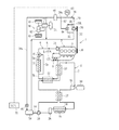
図1は内燃機関の廃熱利用装置の一例を模式的に示しており、この廃熱利用装置1は、車両に搭載され、車両のエンジン(内燃機関)2を冷却する冷却水回路4と、エンジン2の廃熱を回収するランキンサイクル6(以下、RC回路という)とを備えている。
冷却水回路4は、エンジン2から延設される冷却水の循環路5に、冷却水の流れ方向から順に排ガス熱交換器8、後述する過熱器10、後述する蒸発器12、ラジエータ14、サーモスタット16、水ポンプ18が介挿されて閉回路を構成している。
Hereinafter, an embodiment of the present invention will be described first from the first embodiment with reference to the drawings.
FIG. 1 schematically shows an example of a waste heat utilization device for an internal combustion engine. The waste
The cooling water circuit 4 is connected to a cooling
排ガス熱交換器8は、エンジン2を経由し、エンジン2のシリンダブロック3を冷却することにより加熱された冷却水をエンジン2の排ガス管9から排出される排ガスと熱交換させて所定の設定温度まで更に加熱する。
ラジエータ14は、蒸発器12と直列に配列され、蒸発器12にて冷媒に吸熱されて冷却された冷却水を外気などとの熱交換により更に冷却する。
The exhaust
The
サーモスタット16は、ラジエータ14へ通水される冷却水の量をサーモスタット16に流入する冷却水の温度に応じて制御する機械式の三方弁であって、2つの入口ポートと1つの出口ポートとを有している。2つの入口ポートには、ラジエータ14から延設される流路5aと、蒸発器12とラジエータ14との間の流路5bからラジエータ14を迂回して接続されるラジエータバイパス路5cとがそれぞれ接続され、これにより、ラジエータ12へ通水される冷却水の量が冷却水温度に応じて増減されて冷却水温度、ひいてはシリンダブロック3の温度が適正に保持される。
The
水ポンプ18は、エンジン2に装着され、エンジン2の回転数に応じて駆動されて冷却水を冷却水回路4に好適に循環させる。
一方、RC回路6は、作動流体としての例えばフロンR134aなどの冷媒の循環路7に、冷媒の流れ方向から順に、蒸発器12、過熱器10、膨張機20、再生器22、凝縮器24、気液分離器26、冷媒ポンプ28が介挿されて閉回路を構成している。
The
On the other hand, the
蒸発器12は、冷媒ポンプ28にて圧送された冷媒をエンジン2、排ガス熱交換器8、過熱器10を順次経由した冷却水と熱交換させて所定の蒸発温度にて蒸発させる。
過熱器10は、蒸発器12を経由した冷媒を排ガス熱交換器8を経由した冷却水と熱交換させて過熱状態にする。
膨張機20は、過熱器10を経由して過熱状態にされた冷媒を膨張させて回転駆動力を発生する回転機器であって、膨張機20には、膨張機20にて発生した駆動力を電力に変換して廃熱利用装置1の外部で利用可能とする発電機30が同軸にて機械的に連結されている。
The
The
The
再生器22は、膨張機20を経由して凝縮器24に流入する前の冷媒によって冷媒ポンプ28を経由して蒸発器12に流入する前の冷媒を加熱する熱交換器である。
凝縮器24は、再生器22を経由した冷媒をファン25による送風によって外気との熱交換により凝縮液化させる放熱器である。
気液分離器26は、凝縮器24にて凝縮された冷媒を気液二層に分離し、ここで分離された液冷媒のみが冷媒ポンプ28に流出される。
The
The
The gas-
冷媒ポンプ28は、気液分離器26にて分離された液冷媒を蒸発器12側に圧送し、RC回路6に好適に循環させる。
このように構成される冷却水回路4及びRC回路6は、車両を総合的に制御する電子制御装置であるECU32により制御される。
ところで、本実施形態では、車両は、車両を操舵するためのステアリング34を回す補助機構としてのパワーステアリング機構(車両機構)36(以下、パワステ機構という)と、パワステ機構36を駆動させる作動流体としての油が循環する油圧回路(流体圧回路)38とを備えている。
The
The coolant circuit 4 and the
By the way, in this embodiment, the vehicle is a power steering mechanism (vehicle mechanism) 36 (hereinafter referred to as a power steering mechanism) as an auxiliary mechanism for turning the steering 34 for steering the vehicle, and a working fluid for driving the
パワステ機構36は、ステアリング34にて操舵される車輪40、パワーシリンダ42、コントロールバルブ44から構成され、これより車両の運転者はステアリング34を違和感無く軽く切ることができる。
詳しくは、油圧回路38の高圧側と低圧側とは所定圧力差に保持され、パワーシリンダ42に流れ込む油の量によってステアリング34が制御される。例えば、油圧回路38は、車両の運転者がステアリング34を大きく切った場合には、パワーシリンダ42に多量の油を流し、一方、運転者がステアリング34を小さく切った場合には、パワーシリンダ42に少量の油を流す制御を行い、油圧回路38には常時所定量の油が必要とされる。
The
Specifically, the high pressure side and the low pressure side of the
パワーシリンダ42は、車両の低速運転時やエンジン2のアイドリング時においてはステアリング34を軽く、車両の高速運転時においてはステアリング34を若干重めに回転させるべく、油圧回路38によって適宜必要な油圧の油が適量供給される。
コントロールバルブ44は、ステアリング34が回転される方向によってパワーシリンダ42に付与される油圧の方向を切り換え、パワーシリンダ42の動作方向を制御している。
The
The
一方、油圧回路38は、油の循環路39に、油の流れ方向から順に、油圧ポンプ(流体圧ポンプ)46、タンク(アキュームレータ)48、コントロールバルブ44が介挿されて閉回路を構成している。
油圧ポンプ46は、いわゆるベーンポンプ、またはギヤポンプ、またはピストンポンプであって、油を加圧して循環路39に循環させるとともに、パワステ機構36を駆動するための油圧を発生する。油圧ポンプ46の回転軸には、プーリ50及びベルト52を介してエンジン2の駆動力が伝達され、油圧ポンプ46はエンジン2の駆動力によって駆動される。
On the other hand, the
The
タンク48は、油圧ポンプ46によって加圧された高圧側の油の余剰圧力を蓄圧し、蓄圧された油圧によってパワステ機構36を駆動させることができる、いわゆるアキュームレータである。
また、油圧回路38は、油圧ポンプ46をバイパスするバイパス路54を備え、バイパス路54には圧力調整弁56が介挿されている。
The
The
圧力調整弁56は、その弁体を駆動する駆動部に、油圧ポンプ46とタンク48との間の循環路39から延設される導圧管57が接続され、導圧管57から導圧される油圧に応じて開閉される機構弁であり、油圧ポンプ46から送出された油を油圧回路38の低圧側に戻すことによって油圧回路38の高圧側の油が過剰に高圧になるのを防止している。
このように構成される油圧回路38は、車両の低速運転時やアイドリング時においては、油圧ポンプ46による加圧の他、タンク48に蓄圧された油圧を利用するなどして、パワーシリンダ42に流れ込む油の量を多くすることにより、油圧回路38の高圧側と低圧側とを所定圧力差に保持し、ステアリング34の軽い操作を可能とする。一方、車両の高速運転時においては、パワステ機構36を駆動するための必要最低限量の油をパワーシリンダ42に供給することにより、ステアリング34の操作を重くさせる。また、車両の通常運転時において、エンジン2の高回転により油圧ポンプ46が必要以上に高回転域で駆動される場合には、油はバイパス路54に流され、これより油圧回路38の低圧側と高圧側との所定圧力差が保持される。
The
The
ここで、本実施形態の油圧回路38では、コントロールバルブ44と並列に循環路39の並列路39aが設けられ、並列路39aには油圧ポンプ46にて加圧された油の油圧によって駆動される油圧モータ(流体圧モータ)58が介挿され、換言すると、油圧モータ58は油圧回路38においてパワステ機構36に並列に接続されており、冷媒ポンプ28は油圧モータ58によって駆動される。
Here, in the
油圧モータ58は、油圧ポンプ46により発生した油圧によって回転駆動力を発生する回転機器であり、油圧モータ58に流入する油量を制御することで、油圧モータ58の回転軸59の回転速度を制御することができる。回転軸59は冷媒ポンプ28と同軸をなしており、油圧モータ58は冷媒ポンプ28の回転源として利用される。
更に、並列路39aには油圧モータ58に流入される油量を制御する流量調整弁60が介挿されている。
The
Further, a flow
流量調整弁60は、電動開閉弁であって、その駆動部がECU32に電気的に接続されている。
また、循環路39の油圧ポンプ46の下流側のバイパス路54の接続位置39bと導圧管57の接続位置39cとの間には同じくECU32に電気的に接続された圧力センサ(圧力検出手段)62が設けられている。
The flow
Further, a pressure sensor (pressure detection means) 62 which is also electrically connected to the
ここで、凝縮器24にて放熱可能な放熱量は、外気温度や車速などのRC回路6にとっての外乱要素に影響を受け、蒸発器12では、この放熱量に見合う適切な熱量の廃熱を回収するのが好ましい。何故なら、冷媒ポンプ28の回転数が大きくなると、蒸発器12での廃熱回収量が多すぎて凝縮器24にて放熱し切れなくなり、RC回路6における冷媒の低圧側圧力(凝縮圧力)が上昇し、膨張機20前後の冷媒の差圧が低下し、一方、冷媒ポンプ28の回転数が小さすぎると、蒸発器12での廃熱回収量が少なくなり、循環路7を循環する冷媒流量が減少し、何れの場合も膨張機20の回転数低下、すなわちRC回路6の出力低下を招くからである。
Here, the amount of heat dissipated by the
そこで、ECU32は、ECU32に入力される図示しない外気温度センサや車速センサなどの信号に基づいて、RC回路6における実際の廃熱回収量Qを算出するとともに、上記放熱量に見合う目標廃熱回収量Qsを設定する。そして、ECU32は、廃熱回収量Qを目標廃熱回収量Qsに追従させるべくRC回路6の作動を制御し、RC回路6の出力を上昇させている。更に、ECU32は、上記RC回路6の作動制御状況に応じて、流量調整弁60を開閉することにより、油圧モータ58への油の流入量を制御して油圧モータ58の回転数を制御し、ひいては冷媒ポンプ28の回転数を制御し、廃熱回収量Qを目標廃熱回収量Qsに適切に調節するための油圧モータ制御を実行している(制御手段)。
Therefore, the
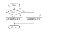
以下、図2のフローチャートを参照して、ECU32において実行される廃熱回収量に応じた油圧モータ制御の制御ルーチンについて説明する。
先ず、本制御が開始されるとS1(Sはステップを表し、以下同様とする。)に移行し、S1では、RC回路6において回収される廃熱回収量Qが目標廃熱回収量Qs以上(Q≧Qs)であるか否かを判定し、判定結果が真(Yes)でQ≧Qsが成立すると判定された場合にはS2に移行し、判定結果が偽(No)でQ≧Qsが成立しないと判定された場合にはS3に移行する。
Hereinafter, a control routine for hydraulic motor control according to the amount of recovered waste heat executed in the
First, when this control is started, the process proceeds to S1 (S represents a step, and the same shall apply hereinafter). In S1, the waste heat recovery amount Q recovered in the
S2では、開弁されている流量調整弁60を閉弁し、または流量調整弁60が既に閉弁されているときは閉弁されたままにして、油圧モータ58への油の流入を制限し、本制御ルーチンをリターンする。
一方、S3では、閉弁されている流量調整弁60を開弁し、油圧モータ58への油の流入量の制限を解除し、または流量調整弁60が既に開弁されているときは開弁されたままにして、油圧モータ58へ油を積極的に流入させ、本制御ルーチンをリターンする。
In S2, the
On the other hand, in S3, the closed flow
また、当該油圧モータ制御では、流量調整弁60は圧力センサ62にて検出された油圧回路38の高圧側の油圧に応じても開閉され、流量調整弁60を制御するための判断情報としては、RC回路6の作動制御状況よりも油圧回路38の高圧側の油圧のほうが優先される(制御手段)。
以下、図3のフローチャートを参照して、ECU32において実行される油圧に応じた油圧モータ制御の制御ルーチンについて説明する。
Further, in the hydraulic motor control, the flow
Hereinafter, a control routine for hydraulic motor control corresponding to the hydraulic pressure executed in the
先ず、本制御が開始されるとS11に移行し、S11では、圧力センサ62にて検出された油圧Pが所定の下限圧力(第1下限圧力)PL1以下(P≦PL1)であるか否かを判定し、判定結果が真(Yes)でP≦PL1が成立すると判定された場合にはS12に移行し、判定結果が偽(No)でP≦PL1が成立しないと判定された場合にはS13に移行する。尚、下限圧力PL1は車両の低速運転時やアイドリング時などにパワステ機構36を駆動するための必要最低限の油圧が設定される。
First, when this control is started, the process proceeds to S11. In S11, is the hydraulic pressure P detected by the
S12では、開弁されている流量調整弁60を閉弁し、または流量調整弁60が既に閉弁されているときは閉弁されたままにして、油圧モータ58への油の流入を制限し、本制御ルーチンをリターンする。
一方、S13では、閉弁されている流量調整弁60を開弁し、油圧モータ58への油の流入量の制限を解除し、または流量調整弁60が既に開弁されているときは開弁されたままにして、油圧モータ58へ油を積極的に流入させ、本制御ルーチンをリターンする。
In S12, the flow
On the other hand, in S13, the closed flow
以上のように、本実施形態では、油圧回路38に油圧ポンプ46にて加圧された油の油圧によって駆動される油圧モータ58が設けられ、冷媒ポンプ28が油圧モータ58によって駆動されることにより、冷媒ポンプ28に一般に高価なインバータモータを使用しなくても、冷媒ポンプ28の回転数を可変できる回転源を確保することができるため、RC回路6、ひいては廃熱利用装置1のコストを大幅に低減することができる。
As described above, in this embodiment, the
また、上記油圧モータ制御を実行することにより、RC回路における廃熱回収量や油圧に応じて油圧モータ58、ひいては冷媒ポンプ28の回転数を制御することができるため、パワステ機構36の駆動に連係させて、冷媒ポンプ28の回転数を適切に可変させることができる。
具体的には、RC回路6の作動制御状況に応じて、油圧モータ58、ひいては冷媒ポンプ28の回転数を制御することにより、RC回路6にて回収する廃熱回収量を凝縮器での放熱量に見合う熱量に適切に調節することができるため、パワステ機構36の駆動に連係させて、冷媒ポンプ28の回転数を適切に可変させることにより、RC回路6の出力低下を確実に防止することができる。
Further, by executing the above hydraulic motor control, the rotational speed of the
Specifically, the amount of waste heat recovered by the
また、圧力センサ62にて検出された油圧Pが下限圧力PL1以下のとき、油圧モータ58への油の流入を制限することにより、車両のアイドリング時や減速時に油圧が低下したときには、この油圧によって油圧モータ58よりもパワステ機構36を優先的に駆動させることができるため、RC回路6の作動制御によって車両の駆動に支障を来すことを防止することができる。
Further, when the oil pressure P detected by the
また、油圧回路38にタンク48が設けられることにより、油圧回路38の高圧側の余剰油圧を蓄圧し、蓄圧した油圧によって油圧モータ58、ひいては冷媒ポンプ28を駆動させることができるため、RC回路6によって車両の駆動に支障を来すことを防止しつつ、RC回路6、ひいては廃熱利用装置1の廃熱回収効率を向上することができる。
更に、油圧モータ58は油圧回路38においてパワステ機構36に並列に接続されることにより、油圧モータ58をパワステ機構36に直列に接続する場合に比して、油圧モータ58の制御によってパワステ機構36の駆動に及ぶ影響を小さくすることができる。
Further, since the
Further, the
次に、本発明の第2実施形態について説明する。
図4は、当該第2実施形態の内燃機関の廃熱利用装置の模式図を概略的に示している。
当該第2実施形態は、上記第1実施形態における油圧ポンプ46の回転源をエンジン2から膨張機20及び/または発電機モータ31に置き換えるものであり、他は上記第1実施形態と同様の構成をなしている。
Next, a second embodiment of the present invention will be described.
FIG. 4 schematically shows a schematic diagram of the internal combustion engine waste heat utilization apparatus of the second embodiment.
In the second embodiment, the rotation source of the
発電機モータ31の回転軸には膨張機20及びプーリ64が連結され、油圧ポンプ46の回転軸には、プーリ50、64及びベルト52を介して膨張機20及び/または発電機モータ31の駆動力が伝達される。
発電機モータ31は、膨張機20の回転によって発電機として機能し、発電機で発生した電気は図示しないバッテリーに蓄電され、所定の場合には発電機モータは上記バッテリーに蓄電された電気によって駆動するモータとして機能するように構成されており、これより油圧ポンプ46は発電機モータ31の駆動力によって駆動される。
The
The
また、車両のアイドリング時など、膨張機20の動力が不足する場合には、ECU32において、圧力センサ62にて検出された油圧Pが所定の下限圧力(第2下限圧力)PL2以下(P≦PL2)となるとき、油圧ポンプ58を発電機モータ31の駆動力によって駆動する(制御手段)。
以上のように、本実施形態では、上記第1実施形態と同様に、インバータモータによらないで冷媒ポンプ28の回転源を確保することができるため、RC回路6、ひいては廃熱利用装置1のコストを大幅に低減することができる。
Further, when the power of the
As described above, in the present embodiment, since the rotation source of the
特に当該第2実施形態では、RC回路6にて発生したエネルギーで、油圧ポンプ46、油圧モータ58、ひいては冷媒ポンプ28を駆動させることにより、RC回路6とパワステ機構36との間においてこれらの駆動エネルギー収支を完結させることができる。従って、エンジン2の駆動力のすべてを車両の駆動に有効活用することができる。
しかも、発電機モータ31によって油圧ポンプ46の駆動をアシストすることができるため、特に、パワステ機構36の駆動に要する駆動力が大きくなり、油圧回路38に要求される油圧が大きくなる一方、RC回路6にて回収される廃熱は少ないという車両のアイドリング時や減速時において、油圧モータ58よりもパワステ機構36を優先的に駆動させることができるため、RC回路6によって車両の駆動に支障を来すことを確実に防止することができる。
Particularly in the second embodiment, the energy generated in the
Moreover, since the driving of the
更に、車両のアイドリング時や減速時において膨張機20の出力が小さい場合であっても、発電機モータ31の蓄電力によって油圧モータ58を駆動し油圧回路38の油圧低下を防止することができるため、RC回路6によって車両の駆動に支障を来すことをより一層確実に防止することができる。
以上で本発明の一実施形態についての説明を終えるが、本発明は上記各実施形態に限定されるものではなく、本発明の趣旨を逸脱しない範囲で種々の変更ができるものである。
Furthermore, even when the output of the
Although the description of one embodiment of the present invention has been completed above, the present invention is not limited to the above-described embodiments, and various modifications can be made without departing from the spirit of the present invention.
例えば、上記各実施形態では、油圧モータ58に流入される油の量を制御する流量調整弁60を用いているが、これに限らず、油圧モータ58をバイパスするバイパス路を設け、バイパス路にバイパス弁を設けてこれを制御するようにしても良い。
また、上記各実施形態では、プーリ50、64及びベルト52を介して駆動力が油圧ポンプ46に伝達されるが、これに限らず、油圧ポンプ46をエンジン2や発電機モータ31と同軸に構成しても良いし、上記各実施形態の各作用効果を得られるようにその回転数を制御するのであれば、油圧ポンプ46を電動ポンプとしても良い。
For example, in each of the embodiments described above, the flow
In each of the above embodiments, the driving force is transmitted to the
ここで、油圧ポンプ46の回転源を膨張機20または発電機モータ31のどちらにする場合においても、圧力センサ62にて検出された油圧Pが所定の設定圧力PSになるように、油圧ポンプ46を膨張機20及び/または発電機モータ31の駆動力によって駆動するのが好ましい(制御手段)。この場合には、膨張機20及び/または発電機モータ31によって油圧回路38の油圧を一定に保持することができるため、車両駆動の安定化を図ることができる。
Here, in the case of either a rotating source of the
更に、上述した制御を実現するために、膨張機20、発電機モータ31、及び油圧ポンプ46を同軸にて連結してRC回路6を構成することにより、RC回路6における省スペース化や、構成部品の削減を図ることができ、RC回路6、ひいては廃熱利用装置1のコストを更に低減することができる。
更にまた、上記各実施形態では、パワステ機構36の油圧回路38をRC回路6と連係させているが、これに限らず、何れも図示しない、車両のアクティブサスペンション機構(車両機構)の油圧回路(流体圧回路)や車両のエアブレーキ機構(車両機構)の空圧回路(流体圧回路)などをRC回路6と連係させても良い。
Further, in order to realize the above-described control, the
Furthermore, in each of the above-described embodiments, the
また、上記各車両機構に限らず、プラント設備等の種々の分野に使用される装置の油圧回路をRC回路と連係させても良い。具体的には、ガスタービン・ボイラ発電装置に設けられた油圧回路をガスタービン・ボイラ発電装置の廃熱を回収するRC回路と連係させることが考えられる。この装置の油圧回路は、例えば、ガスタービンの回転軸の潤滑や、装置に供給される燃料の燃料流量を制御する制御弁の駆動源、ガスタービンに送られる蒸気やガスの流量を制御する制御弁の駆動源として利用されるものが知られている。 Moreover, you may link the hydraulic circuit of the apparatus used for not only each said vehicle mechanism but various fields, such as plant equipment, with RC circuit. Specifically, it is conceivable to link a hydraulic circuit provided in the gas turbine / boiler power generator with an RC circuit that recovers waste heat of the gas turbine / boiler power generator. The hydraulic circuit of this device includes, for example, lubrication of the rotating shaft of the gas turbine, a drive source of a control valve that controls the fuel flow rate of fuel supplied to the device, and a control that controls the flow rate of steam and gas sent to the gas turbine. What is used as a drive source of a valve is known.
1 廃熱利用装置
2 エンジン(内燃機関)
6 ランキンサイクル
7 循環路(冷媒の循環路)
12 蒸発器
20 膨張機
24 凝縮器
28 冷媒ポンプ
30 発電機
31 発電機モータ
36 パワーステアリング機構(車両機構、アクティブサスペンション機構)
38 油圧回路(流体圧回路)
39 循環路(作動流体の循環路)
46 油圧ポンプ(流体圧ポンプ)
48 タンク(アキュームレータ)
58 油圧モータ(流体圧モータ)
62 圧力センサ(圧力検出手段)
1 Waste
6 Rankine cycle 7 Circuit (refrigerant circuit)
DESCRIPTION OF
38 Hydraulic circuit (fluid pressure circuit)
39 Circuit (working fluid circuit)
46 Hydraulic pump (hydraulic pressure pump)
48 tanks (accumulator)
58 Hydraulic motor
62 Pressure sensor (pressure detection means)
Claims (13)
冷媒の循環路に、該冷媒を加熱して蒸発させる蒸発器、該蒸発器を経由した冷媒を膨張させて駆動力を発生する膨張機、該膨張機を経由した冷媒を凝縮させる凝縮器、該凝縮器を経由した冷媒を前記蒸発器に向けて圧送する冷媒ポンプを順次介挿したランキンサイクルとを備え、
前記流体圧回路は、前記流体圧ポンプにて加圧された流体の流体圧によって駆動される流体圧モータが前記作動流体の前記循環路に介挿されてなり、
前記冷媒ポンプは、前記流体圧モータによって駆動されることを特徴とする廃熱利用装置。 A fluid pressure circuit having a fluid pressure pump interposed in the working fluid circulation path to pressurize and circulate the working fluid;
An evaporator that heats and evaporates the refrigerant in a circulation path of the refrigerant; an expander that expands the refrigerant that passes through the evaporator to generate a driving force; a condenser that condenses the refrigerant that passes through the expander; A Rankine cycle sequentially inserted with a refrigerant pump that pumps the refrigerant through the condenser toward the evaporator,
The fluid pressure circuit is configured such that a fluid pressure motor driven by a fluid pressure of a fluid pressurized by the fluid pressure pump is inserted in the circulation path of the working fluid.
The waste heat utilization apparatus, wherein the refrigerant pump is driven by the fluid pressure motor.
前記流体圧回路は、前記流体圧ポンプによって加圧された作動流体の流体圧によって前記車両の駆動をアシストする車両機構を駆動することを特徴とする請求項1の廃熱利用装置。 The evaporator heats and evaporates the refrigerant by waste heat of an internal combustion engine that drives a vehicle,
2. The waste heat utilization apparatus according to claim 1, wherein the fluid pressure circuit drives a vehicle mechanism that assists driving of the vehicle by a fluid pressure of a working fluid pressurized by the fluid pressure pump.
前記制御手段は、前記圧力検出手段にて検出された流体圧が所定の第1下限圧力以下のとき、前記流体圧モータへの作動流体の流入を制限することを特徴とする請求項4の廃熱利用装置。 The fluid pressure circuit has pressure detection means for detecting the fluid pressure of the working fluid pressurized by the fluid pressure pump,
5. The waste of claim 4, wherein the control means limits the inflow of the working fluid to the fluid pressure motor when the fluid pressure detected by the pressure detection means is equal to or lower than a predetermined first lower limit pressure. Heat utilization device.
前記流体圧ポンプは、前記膨張機及び/または前記発電機モータの駆動力によって駆動されることを特徴とする請求項6の廃熱利用装置。 The Rankine cycle has a generator motor connected coaxially to the expander,
The waste heat utilization apparatus according to claim 6, wherein the fluid pressure pump is driven by a driving force of the expander and / or the generator motor.
Priority Applications (1)
| Application Number | Priority Date | Filing Date | Title |
|---|---|---|---|
| JP2009171978A JP2011027000A (en) | 2009-07-23 | 2009-07-23 | Waste heat utilization device |
Applications Claiming Priority (1)
| Application Number | Priority Date | Filing Date | Title |
|---|---|---|---|
| JP2009171978A JP2011027000A (en) | 2009-07-23 | 2009-07-23 | Waste heat utilization device |
Publications (1)
| Publication Number | Publication Date |
|---|---|
| JP2011027000A true JP2011027000A (en) | 2011-02-10 |
Family
ID=43636015
Family Applications (1)
| Application Number | Title | Priority Date | Filing Date |
|---|---|---|---|
| JP2009171978A Pending JP2011027000A (en) | 2009-07-23 | 2009-07-23 | Waste heat utilization device |
Country Status (1)
| Country | Link |
|---|---|
| JP (1) | JP2011027000A (en) |
Cited By (5)
| Publication number | Priority date | Publication date | Assignee | Title |
|---|---|---|---|---|
| WO2012157285A1 (en) * | 2011-05-19 | 2012-11-22 | 千代田化工建設株式会社 | Composite power generation system |
| JP2014037774A (en) * | 2012-08-10 | 2014-02-27 | Hino Motors Ltd | Rankine cycle system |
| EP2789838A1 (en) * | 2013-04-12 | 2014-10-15 | Liebherr Machines Bulle SA | Drive system |
| JP2015075281A (en) * | 2013-10-09 | 2015-04-20 | 日野自動車株式会社 | Rankine cycle system |
| JP2016118176A (en) * | 2014-12-22 | 2016-06-30 | 三井造船株式会社 | Power device |
-
2009
- 2009-07-23 JP JP2009171978A patent/JP2011027000A/en active Pending
Cited By (5)
| Publication number | Priority date | Publication date | Assignee | Title |
|---|---|---|---|---|
| WO2012157285A1 (en) * | 2011-05-19 | 2012-11-22 | 千代田化工建設株式会社 | Composite power generation system |
| JP2014037774A (en) * | 2012-08-10 | 2014-02-27 | Hino Motors Ltd | Rankine cycle system |
| EP2789838A1 (en) * | 2013-04-12 | 2014-10-15 | Liebherr Machines Bulle SA | Drive system |
| JP2015075281A (en) * | 2013-10-09 | 2015-04-20 | 日野自動車株式会社 | Rankine cycle system |
| JP2016118176A (en) * | 2014-12-22 | 2016-06-30 | 三井造船株式会社 | Power device |
Similar Documents
| Publication | Publication Date | Title |
|---|---|---|
| EP2320058B1 (en) | Waste heat utilization device for internal combustion engine | |
| JP5281587B2 (en) | Waste heat utilization device for internal combustion engine | |
| CN103154488B (en) | Apparatus for utilizing waste heat from internal combustion engine | |
| JP5163620B2 (en) | Waste heat regeneration system | |
| JP5053922B2 (en) | Waste heat utilization device for internal combustion engine | |
| US20110088397A1 (en) | Waste heat recovery system | |
| EP2345796A2 (en) | Waste heat recovery system | |
| JP2005201067A (en) | Rankine cycle system | |
| JP2008231981A (en) | Waste heat recovery apparatus for internal combustion engine | |
| JP2009287433A (en) | Waste heat utilizing device for internal combustion engine | |
| JP2008231980A (en) | Waste heat utilization device for internal combustion engine | |
| WO2013002017A1 (en) | Rankine cycle | |
| WO2013046853A1 (en) | Waste heat regeneration system | |
| JP2008255959A (en) | Waste heat utilization apparatus of internal combustion engine | |
| JP2011027000A (en) | Waste heat utilization device | |
| JP5494514B2 (en) | Rankine cycle system | |
| WO2013065371A1 (en) | Waste-heat recovery system | |
| WO2012039225A1 (en) | Rankine cycle device | |
| JP4140543B2 (en) | Waste heat utilization equipment | |
| WO2009125276A1 (en) | Engine waste heat collection system | |
| WO2013002018A1 (en) | Rankine cycle | |
| JP5609707B2 (en) | Rankine cycle system controller | |
| JP6860351B2 (en) | Rankine cycle controller | |
| JP2018155099A (en) | Supercharged air cooling unit | |
| JP2008196342A (en) | Waste heat using device for internal combustion engine |