JP2010533970A - Non-contact transfer device for planar substrates - Google Patents
Non-contact transfer device for planar substrates Download PDFInfo
- Publication number
- JP2010533970A JP2010533970A JP2010516525A JP2010516525A JP2010533970A JP 2010533970 A JP2010533970 A JP 2010533970A JP 2010516525 A JP2010516525 A JP 2010516525A JP 2010516525 A JP2010516525 A JP 2010516525A JP 2010533970 A JP2010533970 A JP 2010533970A
- Authority
- JP
- Japan
- Prior art keywords
- bernoulli
- contact type
- conveying apparatus
- type conveying
- gas flow
- Prior art date
- Legal status (The legal status is an assumption and is not a legal conclusion. Google has not performed a legal analysis and makes no representation as to the accuracy of the status listed.)
- Pending
Links
Images

Classifications
-
- B—PERFORMING OPERATIONS; TRANSPORTING
- B65—CONVEYING; PACKING; STORING; HANDLING THIN OR FILAMENTARY MATERIAL
- B65G—TRANSPORT OR STORAGE DEVICES, e.g. CONVEYORS FOR LOADING OR TIPPING, SHOP CONVEYOR SYSTEMS OR PNEUMATIC TUBE CONVEYORS
- B65G51/00—Conveying articles through pipes or tubes by fluid flow or pressure; Conveying articles over a flat surface, e.g. the base of a trough, by jets located in the surface
- B65G51/02—Directly conveying the articles, e.g. slips, sheets, stockings, containers or workpieces, by flowing gases
- B65G51/03—Directly conveying the articles, e.g. slips, sheets, stockings, containers or workpieces, by flowing gases over a flat surface or in troughs
-
- B—PERFORMING OPERATIONS; TRANSPORTING
- B65—CONVEYING; PACKING; STORING; HANDLING THIN OR FILAMENTARY MATERIAL
- B65G—TRANSPORT OR STORAGE DEVICES, e.g. CONVEYORS FOR LOADING OR TIPPING, SHOP CONVEYOR SYSTEMS OR PNEUMATIC TUBE CONVEYORS
- B65G49/00—Conveying systems characterised by their application for specified purposes not otherwise provided for
- B65G49/05—Conveying systems characterised by their application for specified purposes not otherwise provided for for fragile or damageable materials or articles
- B65G49/06—Conveying systems characterised by their application for specified purposes not otherwise provided for for fragile or damageable materials or articles for fragile sheets, e.g. glass
- B65G49/063—Transporting devices for sheet glass
- B65G49/064—Transporting devices for sheet glass in a horizontal position
- B65G49/065—Transporting devices for sheet glass in a horizontal position supported partially or completely on fluid cushions, e.g. a gas cushion
-
- H—ELECTRICITY
- H01—ELECTRIC ELEMENTS
- H01L—SEMICONDUCTOR DEVICES NOT COVERED BY CLASS H10
- H01L21/00—Processes or apparatus adapted for the manufacture or treatment of semiconductor or solid state devices or of parts thereof
- H01L21/67—Apparatus specially adapted for handling semiconductor or electric solid state devices during manufacture or treatment thereof; Apparatus specially adapted for handling wafers during manufacture or treatment of semiconductor or electric solid state devices or components ; Apparatus not specifically provided for elsewhere
- H01L21/677—Apparatus specially adapted for handling semiconductor or electric solid state devices during manufacture or treatment thereof; Apparatus specially adapted for handling wafers during manufacture or treatment of semiconductor or electric solid state devices or components ; Apparatus not specifically provided for elsewhere for conveying, e.g. between different workstations
- H01L21/67784—Apparatus specially adapted for handling semiconductor or electric solid state devices during manufacture or treatment thereof; Apparatus specially adapted for handling wafers during manufacture or treatment of semiconductor or electric solid state devices or components ; Apparatus not specifically provided for elsewhere for conveying, e.g. between different workstations using air tracks
-
- B—PERFORMING OPERATIONS; TRANSPORTING
- B65—CONVEYING; PACKING; STORING; HANDLING THIN OR FILAMENTARY MATERIAL
- B65G—TRANSPORT OR STORAGE DEVICES, e.g. CONVEYORS FOR LOADING OR TIPPING, SHOP CONVEYOR SYSTEMS OR PNEUMATIC TUBE CONVEYORS
- B65G2249/00—Aspects relating to conveying systems for the manufacture of fragile sheets
- B65G2249/04—Arrangements of vacuum systems or suction cups
- B65G2249/045—Details of suction cups suction cups
Abstract
【課題】周囲の雰囲気及び温度にかかわらず、基板を確実に加速、搬送及び再び制動することが可能な平面状の基板用の非接触型搬送装置を提供すること。
【解決手段】平面状の基板1を搬送路3に沿って搬送する非接触型搬送装置において、搬送路3の両側に所定の間隔をもって複数のベルヌーイチャック2a,2bを配置し、搬送される基板1が搬送路3の両側おけるベルヌーイチャック2a,2bをそれぞれ部分的に覆うよう構成し、基板1の搬送のために、搬送路3の両側におけるベルヌーイチャック2a,2bを、それぞれ左回り又は右回りに回転する気体流5,6を生成するよう構成した。To provide a non-contact type transport device for a planar substrate capable of reliably accelerating, transporting and braking again regardless of the ambient atmosphere and temperature.
In a non-contact type transport apparatus that transports a planar substrate 1 along a transport path 3, a plurality of Bernoulli chucks 2a and 2b are arranged at predetermined intervals on both sides of the transport path 3 and transported. 1 is configured to partially cover Bernoulli chucks 2a and 2b on both sides of the transport path 3, and for transporting the substrate 1, the Bernoulli chucks 2a and 2b on both sides of the transport path 3 are rotated counterclockwise or clockwise, respectively. The gas streams 5 and 6 that rotate in the direction are generated.
Description
本発明は、特に長方形状又は四角形状の損傷しやすいプレートである平面状の基板を搬送路に沿って搬送する非接触型搬送装置に関するものである。 The present invention relates to a non-contact type transport apparatus that transports a flat substrate, which is a rectangular or quadrangular plate that is easily damaged, along a transport path.
例えば高温のプロセス室を通過して搬送される基板は、ガラス、ケイ素、グラファイトなどで形成された、曲げ剛性は高いが損傷しやすい材料からなっている。そのため、このような基板を搬送する際には、非接触型の搬送システムを用いることが有効である。 For example, a substrate conveyed through a high-temperature process chamber is made of a material that is made of glass, silicon, graphite, or the like and has high bending rigidity but is easily damaged. For this reason, it is effective to use a non-contact type transport system when transporting such a substrate.
特許文献1には、半導体ウエハを気体状の搬送手段によって加工ステーションから又は加工ステーションへ搬送する循環システムが開示されている。この搬送手段は自動的に中心合せされるため、半導体ウエハは、常に搬送路の中心に沿って搬送されるようになっている。さらに、半導体ウエハの下方では、半円状の気体ノズルによって、中心合わせ及び前進のための力を有するエアクッションが形成されている。また、動作の停止は、半導体ウエハを所定の箇所に固定する真空停止手段によってなされるようになっている。 Patent Document 1 discloses a circulation system in which a semiconductor wafer is transferred from or to a processing station by a gaseous transfer means. Since the transfer means is automatically centered, the semiconductor wafer is always transferred along the center of the transfer path. Further, below the semiconductor wafer, an air cushion having a force for centering and advancing is formed by a semicircular gas nozzle. The operation is stopped by a vacuum stop means for fixing the semiconductor wafer at a predetermined location.
本発明の目的とするところは、周囲の雰囲気及び温度にかかわらず、基板を(これをさかさまにした場合でも)、確実に加速、搬送及び再び制動することが可能な平面状の基板用の非接触型搬送装置を提供することにある。 The object of the present invention is for a planar substrate that can reliably accelerate, transport and brake again (even when it is upside down) regardless of the ambient atmosphere and temperature. The object is to provide a non-contact type conveying apparatus.
上記目的は、独立請求項に記載した特徴によって達成される。さらに、本発明の各実施形態は、各従属請求項に記載されている。なお、本発明による非接触型搬送装置は、よく知られたベルヌーイ効果を利用したものである。 This object is achieved by the features described in the independent claims. Furthermore, embodiments of the invention are described in the respective dependent claims. The non-contact type conveying apparatus according to the present invention utilizes a well-known Bernoulli effect.
本発明は、長方形状又は四角形状の損傷しやすいプレートである平面状の基板を搬送路に沿って搬送する非接触型搬送装置において、前記搬送路の両側に所定の間隔をもって複数のベルヌーイチャックを配置し、搬送される前記基板が前記搬送路の両側おける前記ベルヌーイチャックをそれぞれ部分的に覆うよう構成し、前記基板の搬送のために、前記搬送路の両側における前記ベルヌーイチャックを、それぞれ左回り又は右回りに回転する気体流を生成するよう構成し、前記搬送路の両側に機械的な側方案内部材を設けたことを特徴としている。 The present invention relates to a non-contact type transport apparatus that transports a planar substrate, which is a rectangular or square plate that is easily damaged, along a transport path, and includes a plurality of Bernoulli chucks at predetermined intervals on both sides of the transport path. The substrate to be transported is configured to partially cover the Bernoulli chucks on both sides of the transport path, and the Bernoulli chucks on both sides of the transport path are counterclockwise for transporting the substrate, respectively. Or it is comprised so that the gas flow which rotates clockwise may be produced | generated, The mechanical side guide member was provided in the both sides of the said conveyance path, It is characterized by the above-mentioned.
また、本発明によれば、テクスチャ化された基板又はウエハをテクスチャ化された側において支持し、搬送することが問題なく行える。さらに、これをさかさまにした場合も同様である。 Further, according to the present invention, it is possible to support and transport the textured substrate or wafer on the textured side without any problem. The same applies to the case where this is turned upside down.
また、側方案内部材としては、複数のレール又は複数の画成枠が考えられる。 Further, as the side guide member, a plurality of rails or a plurality of defined frames can be considered.
本発明の一実施形態は、右回り又は左回りに回転する気体流を形成するために、搬送路に沿った両側において、右回りに回転する気体流を発生させるベルヌーイチャックと左回りに回転する気体流を発生させるベルヌーイチャックを交互に配置したことを特徴としている。これにより、それぞれ2番目の対となっているベルヌーイチャックを制御することで一方向の搬送方向が達成され、一方、他の対となっているベルヌーイチャックを制御することで逆方向の搬送方向が達成される。なお、搬送方向の変更は、ベルヌーイチャックの適当な制御によっても行うことが可能である。 One embodiment of the present invention rotates counterclockwise with a Bernoulli chuck that generates a gas flow that rotates clockwise on both sides along the transport path to form a gas flow that rotates clockwise or counterclockwise. It is characterized by alternately arranging Bernoulli chucks for generating a gas flow. Thus, one direction of conveyance is achieved by controlling the second pair of Bernoulli chucks, while the opposite direction of conveyance is controlled by controlling the other pair of Bernoulli chucks. Achieved. Note that the change of the transport direction can also be performed by appropriate control of the Bernoulli chuck.
また、本発明の一実施形態は、各ベルヌーイチャックを、右回りと左回りのいずれかの気体流に切換可能に形成したことを特徴としている。 Further, one embodiment of the present invention is characterized in that each Bernoulli chuck is formed so as to be switchable to either a clockwise or counterclockwise gas flow.
また、本発明の一実施形態は、搬送路の終端部におけるベルヌーイチャックについては、他のベルヌーイチャックとは逆方向の気体流を生成するよう構成したことを特徴としている。この場合、搬送路の終端部においては、搬送される基板に対して制動効果が作用することになる。 Moreover, one embodiment of the present invention is characterized in that the Bernoulli chuck at the end of the conveyance path is configured to generate a gas flow in the opposite direction to the other Bernoulli chucks. In this case, a braking effect acts on the substrate to be transported at the end portion of the transport path.
また、ベルヌーイチャックを、平面状の支持部材上に配置するとともに、この支持部材にはめ込むか、又は圧入することが考えられる。 Further, it is conceivable that the Bernoulli chuck is disposed on a planar support member and is fitted into or pressed into the support member.
基板の確実な搬送を高温下又は刺激の強い媒体の下でも確保するために、支持部材(場合によってはベルヌーイチャックを含めて)を完全にグラファイトで形成するのがよい。この場合、ベルヌーイチャックは1000℃の高温下かつH2雰囲気下においても問題なく動作し、プロセスガスとベルヌーイチャックで用いられる気体を同一とすることができる。さらに、この気体を予熱したり、循環路を循環させるようにしてもよく、このためには、例えば公知のグラファイトポンプが適している。 In order to ensure reliable transport of the substrate even at high temperatures or under a harsh medium, the support member (including possibly the Bernoulli chuck) may be made entirely of graphite. In this case, the Bernoulli chuck operates without problems even at a high temperature of 1000 ° C. and in an H 2 atmosphere, and the process gas and the gas used in the Bernoulli chuck can be made the same. Furthermore, this gas may be preheated or circulated through a circulation path. For this purpose, for example, a known graphite pump is suitable.
また、本発明の一実施形態は、ベルヌーイチャックを鍋状に形成するとともに、該ベルヌーイチャックの内壁部に、圧縮空気その他の気体を接線方向に供給するための少なくとも1つの気体流出部を設けたことを特徴としている。 In one embodiment of the present invention, the Bernoulli chuck is formed in a pan shape, and at least one gas outflow portion for supplying compressed air or other gas in a tangential direction is provided on the inner wall portion of the Bernoulli chuck. It is characterized by that.
また、本発明の一実施形態は、上方へ向いたらせん状に回転する気体流を発生させるために、気体流出部を、開口部方向すなわち基板方向へわずかに傾斜させて設けたことを特徴としている。 In addition, one embodiment of the present invention is characterized in that the gas outflow portion is provided with a slight inclination in the direction of the opening, that is, in the direction of the substrate, in order to generate a gas flow that rotates in a spiral shape upward. Yes.
さらに、特に均一な気体流を得るために、搬送路の両側それぞれにおける各ベルヌーイチャックの内壁部に、他方の側と互いに対向し、かつ、同方向に向いた気体流出部を設けることが望ましい。 Furthermore, in order to obtain a particularly uniform gas flow, it is desirable to provide gas outflow portions facing the other side and facing in the same direction on the inner wall portions of the Bernoulli chucks on both sides of the transport path.
また、圧縮気体を作用させる際にこの気体の回転方向を変更できるよう、内壁部に、互いに逆方向に回転する気体流を発生させる一対の気体流出部を設けることが考えられる。 It is also conceivable to provide a pair of gas outflow portions that generate gas flows rotating in opposite directions on the inner wall so that the direction of rotation of the gas can be changed when the compressed gas is applied.
本発明は、さかさまとなった搬送、すなわち基板を懸架するような搬送に対しても適用することが可能である。このような懸架状の搬送においては、特に簡易に支持部材によって担持されるか、又は吸引される。この場合には、基板は、ベルヌーイ効果が得られるくらいの小さな間隔でベルヌーイチャックの近傍を通過又は移動する必要がある。 The present invention can also be applied to an upside-down transfer, that is, a transfer in which a substrate is suspended. In such a suspended conveyance, it is particularly easily carried by the support member or sucked. In this case, the substrate needs to pass or move in the vicinity of the Bernoulli chuck at such a small interval as to obtain the Bernoulli effect.
また、登り勾配約30°までであれば問題なく基板の搬送を行うことが可能であり、下り勾配の場合には上述のような制動効果を用いる必要がある。 Further, it is possible to carry the substrate without any problem if the climbing gradient is up to about 30 °. In the case of the descending gradient, it is necessary to use the braking effect as described above.
本発明によれば、周囲の雰囲気及び温度にかかわらず、基板を確実に加速、搬送及び再び制動することが可能である。 According to the present invention, the substrate can be reliably accelerated, transported and braked again regardless of the ambient atmosphere and temperature.
以下に本発明の実施の形態を添付図面に基づいて説明する。 Embodiments of the present invention will be described below with reference to the accompanying drawings.
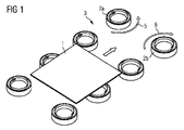
図1には基板1の本発明による非接触型搬送装置の概略が示されており、この基板1は、例えばソーラーセルなどの破損しやすい長方形状又は四角形状のプレートである。また、この非接触型搬送装置においては、搬送路3に沿って、鍋状のベルヌーイチャック2a,2bの2つの列が搬送路3の両側に1列ずつ配置されている。 FIG. 1 shows an outline of a non-contact type conveying apparatus according to the present invention for a substrate 1, and this substrate 1 is a rectangular or quadrangular plate that is easily damaged, such as a solar cell. Further, in this non-contact type conveying apparatus, two rows of pot-shaped Bernoulli chucks 2 a and 2 b are arranged along the conveying path 3, one on each side of the conveying path 3.
しかして、搬送路3の左右それぞれのベルヌーイチャック2a,2bの間の間隔は基板1の幅よりも大きく形成されている。すなわち、基板1は、その搬送時に、最大で各ベルヌーイチャック2a,2bの約半分を覆うことになる。また、左側の列にあるベルヌーイチャック2aは左回り(反時計回り)の気体流5を発生させ、右側の列にあるベルヌーイチャック2bは右回り(時計回り)の気体流6を発生させるようになっており、それぞれ搬送路3において搬送される基板1に向けて気体流を供給するようになっている。
Thus, the distance between the Bernoulli chucks 2 a and 2 b on the left and right sides of the transport path 3 is formed larger than the width of the substrate 1. That is, the substrate 1 covers up to about half of each Bernoulli
なお、基板1とはテクスチャ化されたウエハであり、テクスチャ化された側面のみが担持される。 The substrate 1 is a textured wafer, and only the textured side surface is carried.
ところで、ベルヌーイチャック2a,2bは、適当な材料で形成された支持部材上に配置されているか、又はこの支持部材にはめ込まれるか若しくは圧入されている。この支持部材としてグラファイトプレートを用いることが考えられ、このグラファイトプレートを用いれば、約1000℃までの高温下においても使用することが可能である。なお、支持部材及びベルヌーイチャック2a,2bを、高温に耐えられ、かつ、化学的な抵抗性を有する他の材料(例えばセラミック)で形成してもよい。 By the way, the Bernoulli chucks 2a and 2b are arranged on a support member made of an appropriate material, or are fitted or press-fitted into the support member. It is conceivable to use a graphite plate as the support member. If this graphite plate is used, it can be used even at a high temperature up to about 1000 ° C. Note that the support member and the Bernoulli chucks 2a and 2b may be formed of other materials (for example, ceramic) that can withstand high temperatures and have chemical resistance.
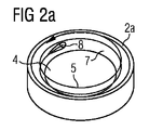
図2aには左回り(反時計回り)の気体流5を発生させるベルヌーイチャック2aが示されており、図2bには右回り(時計回り)の気体流6を発生させるベルヌーイチャック2bが示されている。
Fig. 2a shows a Bernoulli
ここで、図2a及び図2bにはベルヌーイチャック2a,2bの詳細が示されており、これらベルヌーイチャック2a,2bは、搬送される基板1へ向いた開口部4を備えて鍋状に形成されているとともに、その内壁部7において圧縮空気又はその他の気体(例えばプロセスガス)を接線方向に供給する少なくとも1つの気体流出部(ノズル)8を備える構成となっている。なお、この気体流出部(ノズル)8は上方(開口部7方向)へわずかに傾斜しているため、上方へ向いたらせん状に回転する気体流5,6が生成されることになる。
2a and 2b show details of the Bernoulli
また、ベルヌーイチャック2a,2bを完全にグラファイトで形成すれば、これらベルヌーイチャック2a,2bは、1000℃の高温下かつH2雰囲気下においても問題なく動作する。この場合には、プロセスガスとベルヌーイチャック2a,2bで用いられる気体を同一とすることができる。さらに、この気体を予熱したり、循環路を循環させるようにしてもよく、このためには、公知のグラファイトポンプが適している。 Further, if the Bernoulli chucks 2a and 2b are completely formed of graphite, the Bernoulli chucks 2a and 2b operate without problems even at a high temperature of 1000 ° C. and in an H 2 atmosphere. In this case, the process gas and the gas used in the Bernoulli chucks 2a and 2b can be the same. Furthermore, this gas may be preheated or circulated through a circulation path. For this purpose, a known graphite pump is suitable.
また、各ベルヌーイチャック2a,2bの内壁部7にそれぞれ互いに対向する気体流出部8を設けるのが望ましく、これにより、均等な気体流5,6を得ることが可能である。一方、同様のベルヌーイチャック2a,2bによって気体流5,6の回転方向を異なるようにするには、適当な制御により互いに逆方向に回転する気体流を発生する一対の気体流出部(不図示)を内壁部7に設ければよい。
Further, it is desirable to provide
ところで、搬送路3の左側に配置されたベルヌーイチャック2aは左回り(反時計回り)の気体流5を発生させ、搬送路3の右側に配置されたベルヌーイチャック2bは右回り(時計回り)の気体流6を発生させるため、これらベルヌーイチャック2a,2b上に配置された基板1は、図1に示すようにエアクッションによって浮揚し、気体流5,6が基板1の表面部に作用して発生する前進方向への力によって搬送路3に沿って前方へ搬送される。
By the way, the
また、搬送路3に沿って両方向に搬送する場合には、上述したような気体流の回転方向を切換可能なベルヌーイチャックを用いればよい。さらに、搬送路3の左右においてベルヌーイチャック2a,2bを交互に配置することもでき、この場合には、搬送路3に沿って対となるベルヌーイチャック2a,2bは、それぞれ互いに反対の回転方向に気体流を発生する必要がある。これは、搬送路3に沿って両側に並んで配置された後続のベルヌーイチャック2a,2bについても同様である。 When transporting in both directions along the transport path 3, a Bernoulli chuck capable of switching the rotation direction of the gas flow as described above may be used. Further, the Bernoulli chucks 2a and 2b can be alternately arranged on the left and right of the transport path 3. In this case, the Bernoulli chucks 2a and 2b that are paired along the transport path 3 are respectively in opposite rotation directions. It is necessary to generate a gas flow. The same applies to the subsequent Bernoulli chucks 2a and 2b arranged side by side along the conveyance path 3.
これにより、ベルヌーイチャック2a,2bの各対は同方向の前進力を発生させることになる。したがって、気体流出部8を切り換えることで、容易に搬送方向の変更を行うことが可能である。
Thereby, each pair of Bernoulli chucks 2a and 2b generates a forward force in the same direction. Therefore, it is possible to easily change the transport direction by switching the
さらに、搬送路3の終端部においてベルヌーイチャック2a,2bの対を一時的に逆方向へ作動させることで制動効果を発生させ、この終端部において搬送速度を減少させることも可能である。 Furthermore, it is possible to generate a braking effect by temporarily operating the pair of Bernoulli chucks 2a and 2b in the reverse direction at the end portion of the transfer path 3, and to reduce the transfer speed at this end portion.
また、特に大きな基板を搬送する場合には、中間支持部材としてのベルヌーイチャック2a,2bを搬送路3の中間部に設けることが考えられる。ここで、この中間支持部材としてのベルヌーイチャック2a,2bは、必ずしもらせん状の気体流5,6を発生させる必要があるわけではない。また、ここでも、搬送路3の両側に配置されつつ基板1の前方への搬送を行う他のベルヌーイチャック2a,2bは、間隔をおいて配置されている。 Further, when a particularly large substrate is transported, it is conceivable that Bernoulli chucks 2 a and 2 b as intermediate support members are provided in the intermediate portion of the transport path 3. Here, the Bernoulli chucks 2a and 2b as the intermediate support members do not necessarily need to generate the spiral gas flows 5 and 6. Also here, the other Bernoulli chucks 2 a and 2 b that are arranged on both sides of the conveyance path 3 and convey the substrate 1 forward are arranged at intervals.
また、カーブを搬送させることも可能であり、この場合には、カーブ内側のベルヌーイチャックに対してカーブ外側のベルヌーイチャックがより多く設けられる。 It is also possible to convey the curve. In this case, more Bernoulli chucks outside the curve are provided with respect to the Bernoulli chuck inside the curve.
以上説明した本発明の特別な利点は、本発明を様々な雰囲気下、すなわち高温下、低温下及び刺激の強い雰囲気下などにおいて適用することができる点である。また、ベルヌーイチャックの材料を用途に合わせて選択することでも本発明を高温下で適用することが可能である。ベルヌーイチャックの材料としてグラファイトを用いれば、酸素雰囲気下において500℃まで本発明を適用することができる。 The special advantage of the present invention described above is that the present invention can be applied in various atmospheres, that is, in a high temperature, a low temperature, and a strong atmosphere. Further, the present invention can be applied at a high temperature by selecting a material for the Bernoulli chuck according to the application. If graphite is used as the material for Bernoulli chuck, the present invention can be applied up to 500 ° C. in an oxygen atmosphere.
1 基板
2a,2b ベルヌーイチャック
3 搬送路
4 開口部
5 左回り(反時計回り)の気体流
6 右回り(時計回り)の気体流
7 内壁部
8 気体流出部(ノズル)
DESCRIPTION OF SYMBOLS 1 Board |
Claims (12)
前記搬送路(3)の両側に所定の間隔をもって複数のベルヌーイチャック(2a,2b)を配置し、
搬送される前記基板(1)が前記搬送路(3)の両側おける前記ベルヌーイチャック(2a,2b)をそれぞれ部分的に覆うよう構成し、
前記基板(1)の搬送のために、前記搬送路(3)の両側における前記ベルヌーイチャック(2a,2b)を、それぞれ左回り又は右回りに回転する気体流(5,6)を生成するよう構成し、
前記搬送路(3)の両側に機械的な側方案内部材を設けた
ことを特徴とする非接触型搬送装置。 In a non-contact type conveying apparatus that conveys a planar substrate that is a rectangular or rectangular plate that is easily damaged along a conveying path,
A plurality of Bernoulli chucks (2a, 2b) are arranged at predetermined intervals on both sides of the conveyance path (3),
The substrate (1) to be transported is configured to partially cover the Bernoulli chucks (2a, 2b) on both sides of the transport path (3), respectively.
For transporting the substrate (1), a gas flow (5, 6) is generated that rotates the Bernoulli chucks (2a, 2b) on both sides of the transport path (3) counterclockwise or clockwise, respectively. Configure
A non-contact type conveying apparatus characterized in that mechanical side guide members are provided on both sides of the conveying path (3).
Applications Claiming Priority (2)
| Application Number | Priority Date | Filing Date | Title |
|---|---|---|---|
| DE102007033944 | 2007-07-19 | ||
| PCT/EP2008/059530 WO2009010592A1 (en) | 2007-07-19 | 2008-07-21 | Arrangement for the contactless transport of flat substrates |
Publications (2)
| Publication Number | Publication Date |
|---|---|
| JP2010533970A true JP2010533970A (en) | 2010-10-28 |
| JP2010533970A5 JP2010533970A5 (en) | 2011-05-19 |
Family
ID=39768792
Family Applications (1)
| Application Number | Title | Priority Date | Filing Date |
|---|---|---|---|
| JP2010516525A Pending JP2010533970A (en) | 2007-07-19 | 2008-07-21 | Non-contact transfer device for planar substrates |
Country Status (6)
| Country | Link |
|---|---|
| US (1) | US20100290844A1 (en) |
| EP (1) | EP2173645B1 (en) |
| JP (1) | JP2010533970A (en) |
| KR (1) | KR20100053566A (en) |
| DE (1) | DE102008034119A1 (en) |
| WO (1) | WO2009010592A1 (en) |
Cited By (3)
| Publication number | Priority date | Publication date | Assignee | Title |
|---|---|---|---|---|
| WO2015129749A1 (en) * | 2014-02-26 | 2015-09-03 | オイレス工業株式会社 | Non-contact levitation transport apparatus |
| WO2015137318A1 (en) * | 2014-03-11 | 2015-09-17 | オイレス工業株式会社 | Non-contact-type flotation transport apparatus, and transport direction switching method and transport speed adjustment method for same |
| WO2015137319A1 (en) * | 2014-03-11 | 2015-09-17 | オイレス工業株式会社 | Non-contact floating transport device |
Families Citing this family (8)
| Publication number | Priority date | Publication date | Assignee | Title |
|---|---|---|---|---|
| DE102008041250A1 (en) * | 2008-08-13 | 2010-02-25 | Ers Electronic Gmbh | Method and device for the thermal processing of plastic discs, in particular mold wafers |
| KR101537289B1 (en) * | 2010-04-12 | 2015-07-16 | 에이에스엠엘 네델란즈 비.브이. | Substrate handling apparatus and lithographic apparatus |
| US8905680B2 (en) | 2011-10-31 | 2014-12-09 | Masahiro Lee | Ultrathin wafer transport systems |
| JP5979594B2 (en) * | 2012-09-13 | 2016-08-24 | 村田機械株式会社 | Suction chuck and transfer device provided with the same |
| US9961782B2 (en) * | 2016-07-08 | 2018-05-01 | Kateeva, Inc. | Transport path correction techniques and related systems, methods and devices |
| CN106829481A (en) * | 2017-04-18 | 2017-06-13 | 武汉华星光电技术有限公司 | A kind of conveyer |
| CN111824772A (en) * | 2019-04-19 | 2020-10-27 | 夏普株式会社 | Conveying device |
| JP7437187B2 (en) * | 2020-02-26 | 2024-02-22 | Jswアクティナシステム株式会社 | Levitation conveyance device and laser processing device |
Citations (12)
| Publication number | Priority date | Publication date | Assignee | Title |
|---|---|---|---|---|
| JPS5174381A (en) * | 1974-11-20 | 1976-06-28 | Chemical Reaktor Equip As | |
| JPS5244177A (en) * | 1975-10-01 | 1977-04-06 | Ibm | System for transferring pieces under treatment |
| JPH03200628A (en) * | 1989-12-28 | 1991-09-02 | Shin Meiwa Ind Co Ltd | Floating conveyor |
| JPH07257715A (en) * | 1994-03-17 | 1995-10-09 | Hiroshi Akashi | Afloat conveying device |
| JP2000191137A (en) * | 1998-12-28 | 2000-07-11 | Nippon Electric Glass Co Ltd | Non contact carrier device of plate article |
| JP2000511354A (en) * | 1996-05-31 | 2000-08-29 | アイペック・プリシジョン・インコーポレーテッド | Non-contact cage for wafer-like articles |
| JP2002064130A (en) * | 2000-06-09 | 2002-02-28 | Harmotec Corp | Non-contact transfer device |
| JP2005191464A (en) * | 2003-12-26 | 2005-07-14 | Harmotec Corp | Aligning mechanism and wafer conveying hand |
| JP2005251948A (en) * | 2004-03-03 | 2005-09-15 | Izumi Akiyama | Non-contact holding device and non-contact holding/conveying device |
| JP2006076690A (en) * | 2004-09-08 | 2006-03-23 | Nagaoka Univ Of Technology | Non-contact conveyance device |
| JP2006114748A (en) * | 2004-10-15 | 2006-04-27 | Taiheiyo Cement Corp | Noncontact sucking fixture and noncontact chucking device |
| JP2007176638A (en) * | 2005-12-27 | 2007-07-12 | Harmotec Corp | Non-contact conveying device |
Family Cites Families (12)
| Publication number | Priority date | Publication date | Assignee | Title |
|---|---|---|---|---|
| US3614168A (en) * | 1969-09-30 | 1971-10-19 | Bowles Fluidics Corp | Bernoulli conveyor |
| US4004349A (en) * | 1975-10-21 | 1977-01-25 | Oxy Metal Industries Corporation | Method for fluid conveyance of articles |
| CA1054963A (en) * | 1976-01-16 | 1979-05-22 | John W. Neumann | Fluid rail conveying apparatus |
| FR2504035B1 (en) * | 1981-04-21 | 1986-06-06 | Mitsubishi Heavy Ind Ltd | BLOW MOLDING MACHINE |
| US4630975A (en) * | 1983-10-11 | 1986-12-23 | Becker John H | Air encasement system for transportation of particulates |
| JP2544911B2 (en) * | 1986-05-09 | 1996-10-16 | 曙ブレーキ工業株式会社 | Anti-skid control method |
| DE3936846C1 (en) * | 1989-11-06 | 1991-04-18 | Hilmar 5653 Leichlingen De Vits | |
| US5788425A (en) * | 1992-07-15 | 1998-08-04 | Imation Corp. | Flexible system for handling articles |
| US5468299A (en) * | 1995-01-09 | 1995-11-21 | Tsai; Charles S. | Device comprising a flat susceptor rotating parallel to a reference surface about a shaft perpendicular to this surface |
| US6074085A (en) * | 1997-12-20 | 2000-06-13 | Usbi Co. | Cyclonic mixer |
| US6125754A (en) * | 1998-10-30 | 2000-10-03 | Harris; J. C. | Web pressurizing channeled roller and method |
| JP4243766B2 (en) * | 2006-10-02 | 2009-03-25 | Smc株式会社 | Non-contact transfer device |
-
2008
- 2008-07-21 WO PCT/EP2008/059530 patent/WO2009010592A1/en active Application Filing
- 2008-07-21 EP EP08775255A patent/EP2173645B1/en not_active Not-in-force
- 2008-07-21 DE DE102008034119A patent/DE102008034119A1/en not_active Withdrawn
- 2008-07-21 KR KR1020107003766A patent/KR20100053566A/en not_active Application Discontinuation
- 2008-07-21 US US12/669,515 patent/US20100290844A1/en not_active Abandoned
- 2008-07-21 JP JP2010516525A patent/JP2010533970A/en active Pending
Patent Citations (12)
| Publication number | Priority date | Publication date | Assignee | Title |
|---|---|---|---|---|
| JPS5174381A (en) * | 1974-11-20 | 1976-06-28 | Chemical Reaktor Equip As | |
| JPS5244177A (en) * | 1975-10-01 | 1977-04-06 | Ibm | System for transferring pieces under treatment |
| JPH03200628A (en) * | 1989-12-28 | 1991-09-02 | Shin Meiwa Ind Co Ltd | Floating conveyor |
| JPH07257715A (en) * | 1994-03-17 | 1995-10-09 | Hiroshi Akashi | Afloat conveying device |
| JP2000511354A (en) * | 1996-05-31 | 2000-08-29 | アイペック・プリシジョン・インコーポレーテッド | Non-contact cage for wafer-like articles |
| JP2000191137A (en) * | 1998-12-28 | 2000-07-11 | Nippon Electric Glass Co Ltd | Non contact carrier device of plate article |
| JP2002064130A (en) * | 2000-06-09 | 2002-02-28 | Harmotec Corp | Non-contact transfer device |
| JP2005191464A (en) * | 2003-12-26 | 2005-07-14 | Harmotec Corp | Aligning mechanism and wafer conveying hand |
| JP2005251948A (en) * | 2004-03-03 | 2005-09-15 | Izumi Akiyama | Non-contact holding device and non-contact holding/conveying device |
| JP2006076690A (en) * | 2004-09-08 | 2006-03-23 | Nagaoka Univ Of Technology | Non-contact conveyance device |
| JP2006114748A (en) * | 2004-10-15 | 2006-04-27 | Taiheiyo Cement Corp | Noncontact sucking fixture and noncontact chucking device |
| JP2007176638A (en) * | 2005-12-27 | 2007-07-12 | Harmotec Corp | Non-contact conveying device |
Cited By (6)
| Publication number | Priority date | Publication date | Assignee | Title |
|---|---|---|---|---|
| WO2015129749A1 (en) * | 2014-02-26 | 2015-09-03 | オイレス工業株式会社 | Non-contact levitation transport apparatus |
| JP2015162487A (en) * | 2014-02-26 | 2015-09-07 | オイレス工業株式会社 | Non-contact floating and carrying device |
| WO2015137318A1 (en) * | 2014-03-11 | 2015-09-17 | オイレス工業株式会社 | Non-contact-type flotation transport apparatus, and transport direction switching method and transport speed adjustment method for same |
| WO2015137319A1 (en) * | 2014-03-11 | 2015-09-17 | オイレス工業株式会社 | Non-contact floating transport device |
| JP2015173173A (en) * | 2014-03-11 | 2015-10-01 | オイレス工業株式会社 | Non-contact floating carrier device, and methods for switching carriage direction and adjusting carriage speed thereof |
| JP2015171924A (en) * | 2014-03-11 | 2015-10-01 | オイレス工業株式会社 | Non-contact type floating conveyance device |
Also Published As
| Publication number | Publication date |
|---|---|
| KR20100053566A (en) | 2010-05-20 |
| EP2173645B1 (en) | 2012-05-30 |
| US20100290844A1 (en) | 2010-11-18 |
| DE102008034119A1 (en) | 2009-01-22 |
| WO2009010592A1 (en) | 2009-01-22 |
| EP2173645A1 (en) | 2010-04-14 |
Similar Documents
| Publication | Publication Date | Title |
|---|---|---|
| JP2010533970A (en) | Non-contact transfer device for planar substrates | |
| US20110005899A1 (en) | Method and conveyor belt system having at least one conveyor belt for transporting flat transport goods | |
| JP4755498B2 (en) | Heating apparatus and heating method | |
| JP2010533970A5 (en) | ||
| JP5415401B2 (en) | Method for depositing material on non-planar surface | |
| KR20130094785A (en) | Method and apparatus for contactlessly advancing substrates | |
| JP2010077508A (en) | Film deposition apparatus and substrate processing apparatus | |
| TW201023293A (en) | Substrate processing apparatus and substrate processing method | |
| WO2006128018A2 (en) | Device and method for the reduction of particles in the thermal treatment of rotating substrates | |
| JP2009545891A (en) | Bernoulli Wand | |
| JP2011056335A (en) | Apparatus for pre-drying and method of pre-drying | |
| TW200849447A (en) | Systems and methods for transport through curved conveyance sections | |
| CN104937706A (en) | System and method for processing substrates | |
| KR102552110B1 (en) | Processing apparatus | |
| JP2016180563A (en) | Heating drying device | |
| JP2004345814A (en) | Floatation transport device | |
| JP2000062951A (en) | Conveying apparatus | |
| JP5372695B2 (en) | Substrate processing equipment | |
| JP4360545B2 (en) | Continuous heat treatment furnace | |
| US20060045667A1 (en) | Substrate handling system and process for manufacturing large substrates | |
| WO2016132651A1 (en) | Carrier transport device and carrier transport method | |
| JP2008266010A (en) | Air-floating carrying device using travel passage with guide groove | |
| JP6496919B2 (en) | Bernoulli hand and semiconductor manufacturing equipment | |
| WO2008035324A2 (en) | Apparatus for fluid treatment | |
| JPS5943365B2 (en) | Conveying device for circular thin plate bodies |
Legal Events
| Date | Code | Title | Description |
|---|---|---|---|
| A521 | Request for written amendment filed |
Free format text: JAPANESE INTERMEDIATE CODE: A523 Effective date: 20110404 |
|
| A621 | Written request for application examination |
Free format text: JAPANESE INTERMEDIATE CODE: A621 Effective date: 20110404 |
|
| RD04 | Notification of resignation of power of attorney |
Free format text: JAPANESE INTERMEDIATE CODE: A7424 Effective date: 20100604 |
|
| A977 | Report on retrieval |
Free format text: JAPANESE INTERMEDIATE CODE: A971007 Effective date: 20120802 |
|
| A131 | Notification of reasons for refusal |
Free format text: JAPANESE INTERMEDIATE CODE: A131 Effective date: 20120828 |
|
| A02 | Decision of refusal |
Free format text: JAPANESE INTERMEDIATE CODE: A02 Effective date: 20130226 |