JP2010253446A5 - - Google Patents
Download PDFInfo
- Publication number
- JP2010253446A5 JP2010253446A5 JP2009109843A JP2009109843A JP2010253446A5 JP 2010253446 A5 JP2010253446 A5 JP 2010253446A5 JP 2009109843 A JP2009109843 A JP 2009109843A JP 2009109843 A JP2009109843 A JP 2009109843A JP 2010253446 A5 JP2010253446 A5 JP 2010253446A5
- Authority
- JP
- Japan
- Prior art keywords
- gantry
- substrate
- paste
- moving mechanism
- moves
- Prior art date
- Legal status (The legal status is an assumption and is not a legal conclusion. Google has not performed a legal analysis and makes no representation as to the accuracy of the status listed.)
- Granted
Links
Images
Description
従来のペースト塗布装置として、ペーストパターンが描画される基板を保持した基板保持機構が架台上に設けられ、また、複数の塗布ヘッドをY軸方向に移動可能に設けられた2個のヘッド支持機構が架台上に設けられ、これらヘッド支持機構の一方を固定し、他方を架台上でX軸方向に移動させるようにし、これら塗布ヘッド部のY軸方向への移動とヘッド支持機構のX軸方向への移動とともに、塗布ヘッド部で基板上にペーストを塗布することにより、基板上に所定のペーストパターンを描画するようにしたペースト塗布装置が提案されている(例えば、特許文献1参照)。 As a conventional paste coating apparatus, a substrate holding mechanism that holds a substrate on which a paste pattern is drawn is provided on a gantry, and two head support mechanisms are provided that are capable of moving a plurality of coating heads in the Y-axis direction. There is provided on the frame, fixed to one of these head support mechanisms, the other is to move in the X-axis direction on the gantry, X-axis direction movement and head support mechanism in the Y-axis direction of the coating head A paste application apparatus has been proposed in which a predetermined paste pattern is drawn on a substrate by applying a paste on the substrate with an application head unit as the movement proceeds to (see, for example, Patent Document 1).
上記目的を達成するために、本発明の第1の手段は、ノズル吐出口からペーストを吐出する塗布ヘッドがガントリの鉛直側面に設置されて、塗布ヘッドはガントリの長手方向に移動機構で移動し、ガントリが架台上に設置され、架台上に設置された基板載置テーブルに載置された基板に対してガントリが移動し、ノズル吐出口から基板上にペーストを吐出するペースト塗布装置において、架台上の基板載置テーブルの外側にガントリの移動機構を設け、ガントリの移動機構にガントリを締結ボルトで固定するガントリ取り付け手段を設け、ガントリの大きさは、ガントリの両端部が架台の側面から突出する大きさであって、塗布ヘッドは基板の上部を外れた位置まで移動することを特徴とする。 In order to achieve the above object, according to a first means of the present invention , an application head for discharging paste from a nozzle discharge port is installed on a vertical side surface of a gantry, and the application head is moved by a moving mechanism in the longitudinal direction of the gantry. In a paste application apparatus in which a gantry is installed on a gantry and the gantry moves relative to a substrate placed on a substrate placing table placed on the gantry and discharges paste from the nozzle discharge port onto the substrate. the moving mechanism of the gantry outside the substrate placement table above is provided, provided the gantry attachment means to affix the gantry moving mechanism of the gantry by a fastening bolt, the size of the gantry, both end portions of the gantry from the side of the mount The coating head has a protruding size, and the coating head moves to a position off the top of the substrate .
上記目的を達成するために、本発明の第2の手段は、ノズル吐出口からペーストを吐出する塗布ヘッドがガントリの鉛直側面に設置されて、塗布ヘッドはガントリの長手方向に移動機構で移動し、ガントリが架台上に設置され、架台上に設置された基板載置テーブルに載置された基板に対してガントリが移動し、ノズル吐出口から基板上にペーストを吐出するペースト塗布装置において、架台上の基板載置テーブルよりも下側にガントリの移動機構を設け、ガントリの移動機構にガントリを締結ボルトで固定するガントリ取り付け手段を設け、ガントリの大きさは、ガントリの両端部が架台の側面から突出する大きさであって、塗布ヘッドは基板の上部を外れた位置まで移動することを特徴とする。 To achieve the above object, a second aspect of the present invention, the coating head for discharging a paste from a nozzle ejection port is disposed in a vertical side surface of the gantry, the coating head is moved in the moving mechanism in the longitudinal direction of the gantry In a paste application apparatus in which a gantry is installed on a gantry and the gantry moves relative to a substrate placed on a substrate placing table placed on the gantry and discharges paste from the nozzle discharge port onto the substrate. provided the moving mechanism of the gantry below the substrate mounting table above, provided gantry attachment means to affix the gantry moving mechanism of the gantry by a fastening bolt, the size of the gantry, both end portions of the gantry of the gantry The coating head has a size protruding from the side surface, and the coating head moves to a position off the top of the substrate .
本発明の第3の手段は、第1の手段において、ガントリの移動機構およびガントリ取り付け手段は、基板載置テーブルよりも低い位置に設けたことを特徴とする。 According to a third means of the present invention, in the first means, the gantry moving mechanism and the gantry mounting means are provided at a position lower than the substrate mounting table.
上記目的を達成するために、本発明の第4の手段は、ノズル吐出口からペーストを吐出する塗布ヘッドがガントリの鉛直側面に設置されて、塗布ヘッドはガントリの長手方向に移動機構で移動し、ガントリが架台上に設置され、架台上に設置された基板載置テーブルに載置された基板に対してガントリが移動し、ノズル吐出口から基板上にペーストを吐出するペースト塗布方法において、架台上の基板載置テーブルの外側にガントリの移動機構を設けてガントリを移動させ、ガントリの移動機構でガントリについてのガントリの移動機構からの取り外し、並びにガントリの移動機構への取り付けを締結ボルトによって行なうガントリ取り付け手段を含む構成とし、ガントリの大きさは、ガントリの両端部が架台の側面から突出する大きさであって、塗布ヘッドは基板の上部を外れた位置まで移動することを特徴とする。 In order to achieve the above object, the fourth means of the present invention is that an application head for discharging paste from a nozzle discharge port is installed on a vertical side surface of a gantry, and the application head moves by a moving mechanism in the longitudinal direction of the gantry. In the paste application method , the gantry is installed on a gantry, the gantry moves relative to the substrate placed on the substrate placing table placed on the gantry, and the paste is discharged onto the substrate from the nozzle discharge port. on the outer side of the substrate mounting table above by providing a mechanism for moving the gantry to move the gantry performed, removal from the gantry moving mechanism for gantry moving mechanism of the gantry, as well as by attaching the fastening bolt to the gantry moving mechanism a structure comprising a gantry mounting means, the size of the gantry, the size der both ends of the gantry protrudes from the side surface of the mount Te, coating head thus being moved to a position outside the upper portion of the substrate.
上記目的を達成するために、本発明の第5の手段は、ノズル吐出口からペーストを吐出する塗布ヘッドがガントリの鉛直側面に設置されて、塗布ヘッドはガントリの長手方向に移動機構で移動し、ガントリが架台上に設置され、架台上に設置された基板載置テーブルに載置された基板に対してガントリが移動し、ノズル吐出口から基板上にペーストを吐出するペースト塗布方法において、架台上の基板載置テーブルよりも下側にガントリの移動機構を設けてガントリを移動させ、ガントリの移動機構でガントリについてのガントリの移動機構からの取り外し、並びにガントリの移動機構への取り付けを締結ボルトによって行なうガントリ取り付け手段を含む構成とし、ガントリの大きさは、ガントリの両端部が架台の側面から突出する大きさであって、塗布ヘッドは基板の上部を外れた位置まで移動することを特徴とする。 In order to achieve the above object, according to a fifth means of the present invention , an application head for discharging paste from a nozzle discharge port is installed on a vertical side surface of the gantry, and the application head is moved by a moving mechanism in the longitudinal direction of the gantry. In the paste application method , the gantry is installed on a gantry, the gantry moves relative to the substrate placed on the substrate placing table placed on the gantry, and the paste is discharged onto the substrate from the nozzle discharge port. than the substrate mounting table above to move the gantry to provide a moving mechanism of the gantry on the lower side, detached from the gantry moving mechanism for gantry moving mechanism of the gantry, as well as fastening bolts attachment to the moving mechanism of the gantry a structure comprising a gantry mounting means, the size of the gantry, the size both ends of the gantry projects from the side surface of the pedestal is performed by There, the coating head is thus being moved to a position outside the upper portion of the substrate.
本発明の第6の手段は、第4の手段において、ガントリの移動機構およびガントリ取り付け手段は、基板載置テーブルよりも低い位置に設けられていることを特徴とする。 According to a sixth means of the present invention, in the fourth means, the gantry moving mechanism and the gantry mounting means are provided at a position lower than the substrate mounting table.
また、架台上でのガントリの移動による摺動部は、架台の辺部にガラス基板が載置されるテーブルよりも下側に配置されるものであり、これにより、装置の設置面積の増加が抑圧されつつ、ダウンフローの空調環境下でガントリの摺動部で発生する塵芥が製品となるガラス基板に落下しにくい構造とするものである。 In addition, the sliding part due to the movement of the gantry on the gantry is arranged below the table on which the glass substrate is placed on the side of the gantry, which increases the installation area of the device. it is suppressed, in which dust generated in the sliding portion of the gantry under air-conditioned environment downflow is unlikely to fall into the glass substrate as a product structure.
架台1上のこの基板保持機構8の両側の下側には、X軸方向に沿う架台1の両側の辺部に沿ってX軸方向移動機構6a,6bが設けられている。これらX軸方向移動機構6a,6bは夫々、ここでは、例えば、リニアモータを形成するものであって、その磁石板7がX軸方向に沿って設置されている。これらX軸方向移動機構6a,6b上に2つのガントリ2a,2bが載置・支持されており、これらX軸方向移動機構6a,6bにより、X軸方向に移動することができる。使用される最大幅の基板に対し、架台1のY軸方向の幅(以下、横幅という)をできるだけ小さくしてできるだけ小型化するために、この横幅方向の対向する辺に設けられた磁石板7は、架台1のX軸方向の側面(即ち、架台側面)1a,1bに近接して設置されている。 Below the both sides of the substrate holding mechanism 8 on the gantry 1, X-axis direction moving mechanisms 6 a and 6 b are provided along the sides on both sides of the gantry 1 along the X-axis direction. Each of these X-axis direction moving mechanisms 6a and 6b forms a linear motor here, for example, and the magnet plate 7 is installed along the X-axis direction. Two gantry 2a, 2b is mounted and supported on these X-axis direction moving mechanisms 6a, 6b, and can be moved in the X-axis direction by these X-axis direction moving mechanisms 6a, 6b. In order to reduce the width of the gantry 1 in the Y- axis direction (hereinafter referred to as the lateral width) as much as possible and to reduce the size as much as possible with respect to the maximum width substrate to be used, the magnet plates 7 provided on the opposite sides in the lateral width direction Are installed in the vicinity of the side surface (that is, the side surface of the gantry) 1a, 1b of the gantry 1 in the X-axis direction.
ここで、図面上手前側のガントリ2bについて説明すると、このガントリ2bは、X軸方向に垂直なY軸方向に長い横梁3bと、この横梁3bの両端部に設けられ、この横梁3bを支持する脚状の2つの横梁側支持部材4a,4bとからなり、これら横梁側支持部材4a,4bが夫々X軸方向移動機構6a,6bに移動可能に設けられている架台側支持部材(スライダ)5a,5bに取り付けられている。 Here, to describe the drawings good front gantry 2b, the gantry 2b has a long cross beam 3b in the Y-axis direction perpendicular to the X-axis direction, provided at both ends of the cross beams 3b, supporting the cross beam 3 b The frame-side support member (slider) 5a is composed of two leg-shaped support members 4a and 4b in the form of legs, and these cross beam-side support members 4a and 4b are movably provided in the X-axis direction moving mechanisms 6a and 6b, respectively. , 5b.
ガントリ2bの横梁3bは架台1のY軸方向の幅よりも長く、このため、横梁3bの両端部は架台1のX軸に平行な両側の側面、即ち、架台側面1a,1bから突出しており、このため、この横梁3bの両端部の下面に設けられている横梁側支持部材4a,4bも夫々、架台1のかかる両側の架台側面1a,1bから突出している。これにより、ガントリ2bは、横梁3bが基板保持機構8を横梁側支持部材4a,4bと架台側支持部材5a,5bとで抱え込んでいるような形状をなしている。 The lateral beam 3b of the gantry 2b is longer than the width of the gantry 1 in the Y- axis direction. For this reason, both ends of the lateral beam 3b protrude from the side surfaces parallel to the X axis of the gantry 1, that is, the gantry side surfaces 1a and 1b. For this reason, the transverse beam side support members 4a and 4b provided on the lower surfaces of both ends of the transverse beam 3b also protrude from the gantry side surfaces 1a and 1b on both sides of the gantry 1, respectively. Thus, the gantry 2b has a shape in which the cross beam 3b holds the substrate holding mechanism 8 between the cross beam side support members 4a and 4b and the gantry side support members 5a and 5b.
ガントリ2a,2bの横梁3a,3bの互いに対向するヘッド設置面9には夫々、複数の塗布ヘッド部10が設けられている。図1では、向う側のガントリ2aのヘッド設置面9が正面側を向いて示しているので、以下、このガントリ2aのヘッド設置面9について説明する。 A plurality of coating head portions 10 are provided on the head installation surfaces 9 of the transverse beams 3a and 3b of the gantry 2a and 2b facing each other. In FIG. 1, the head installation surface 9 of the gantry 2a on the opposite side is shown facing the front side, and therefore, the head installation surface 9 of the gantry 2a will be described below.
ガントリ2aのヘッド設置面9には、その面の長手方向(即ち、Y軸方向)に沿ってY軸方向移動機構11が設けられており、このY軸方向移動機構11に複数の塗布ヘッド部10が取り付けられている(なお、ここでは、1つの塗布ヘッド部10にのみ符号を付している)。これら塗布ヘッド部10には夫々、Y軸方向移動機構11のリニアモータが設けられており、かかるリニアモータが、これら塗布ヘッド部10をY軸方向移動機構11に沿ってY軸方向に移動させる。なお、以下の説明では、かかるX軸方向移動機構についても、Y軸方向移動機構11として説明する。 The head installation surface 9 of the gantry 2a is provided with a Y-axis direction moving mechanism 11 along the longitudinal direction of the surface (that is, the Y-axis direction). The Y-axis direction moving mechanism 11 includes a plurality of coating head portions. 10 is attached (here, only one coating head unit 10 is provided with a reference numeral). Husband These coating head portion 10 s is provided with Y-axis direction moving mechanism 1 1 of the linear motor, such linear motor, move these coating head 10 in the Y-axis direction along the Y-axis direction moving mechanism 11 Let In the following description, the X-axis direction moving mechanism is also described as the Y-axis direction moving mechanism 11.
図2は図1における塗布ヘッド部10の一具体例の要部を拡大して示す斜視図であって、15はペースト収納筒、16はノズル支持具、17はノズル、18は距離計、19は基板である。 Figure 2 is a perspective view showing an enlarged main part of an example of a coating head portion 1 0 of FIG. 1, 15 is a paste containing cylinder, 16 is a nozzle support, 17 nozzles, 18 rangefinder Reference numeral 19 denotes a substrate.
距離計18は、ノズル17の先端部から基板保持機構8(図1)に搭載されている基板19の表面(上面)までの距離を非接触式の三角測距法で計測する。即ち、距離計18の筐体内に発光素子が設けられ、この発光素子から放射されたレーザ光は基板19上の計測点Sで反射し、同じく筐体内に設けられた受光素子での受光位置に応じて計測される。また、基板19上でのレーザ光の計測点Sとノズル17の直下位置とは、基板19上で僅かな距離ΔX及びΔYだけずれているが、この僅かな距離程度のずれは基板19の表面の凹凸の差が無視できる範囲に含まれるので、距離計18の計測結果とノズル17の先端部から基板19の表面(上面)までの距離との間に差は殆ど存在しない。従って、この距離計18の計測結果に基いてZ軸移動テーブル14を制御することにより、基板19の表面の凹凸(うねり)に合わせてノズル17の先端部から基板19の表面(上面)までの距離(間隔)を一定に維持することができる。 The distance meter 18 measures the distance from the tip of the nozzle 17 to the surface (upper surface) of the substrate 19 mounted on the substrate holding mechanism 8 (FIG. 1) by a non-contact type triangulation method. That is, a light emitting element is provided in the casing of the distance meter 18, and the laser light emitted from the light emitting element is reflected at the measurement point S on the substrate 19, and is received at the light receiving position by the light receiving element also provided in the casing. Measured accordingly. Further, the position directly below the laser beam of the measurement point S and the nozzle 17 on the substrate 19, but are offset by a small distance ΔX and ΔY on the substrate 19, Re not on the order of this slight distance board 19 the difference of unevenness of the surface of the are within the scope negligible difference between the distance to the surface (upper surface) of the distance meter 18 and a measurement result in the substrate 19 from the tip of the nozzle 17 hardly exists. Therefore, by controlling the Z-axis moving table 14 based on the measurement result of the distance meter 18, the distance from the tip of the nozzle 17 to the surface (upper surface) of the substrate 19 is adjusted according to the unevenness (undulation) of the surface of the substrate 19. The distance (interval) can be kept constant.
なお、図示しないが、照明の可能な光源を備えた鏡筒と画像認識カメラは、各塗布ノズル17の平行調整や間隔調整用に使用される他、基板19の位置合わせやペーストパターンの形状認識などのために、基板に対向するように設けられている。 Although not shown, a lens barrel and an image recognition camera having a light source capable of illumination are used for parallel adjustment and spacing adjustment of each coating nozzle 17 , as well as alignment of the substrate 19 and shape recognition of the paste pattern. For example, it is provided to face the substrate.
図1に戻って、この実施形態では、以上の各部を制御する制御部を備えている。即ち、架台1の内部には、各機構の駆動を行なうリニアモータとテーブルを移動させるサーボモータを制御する主制御部が設けられている。そして、この主制御部に、ケーブルを介して、副制御部に接続されている。副制御部は、Z軸移動テーブル14を駆動するZ軸サーボモータ12を制御する。 Returning to FIG. 1, this embodiment includes a control unit that controls the above-described units. That is, a main control unit that controls a linear motor that drives each mechanism and a servo motor that moves the table is provided inside the gantry 1. The main control unit is connected to the sub-control unit via a cable. Sub-control unit controls the Z-axis servo motor 1 2 for driving the Z-axis moving table 14.
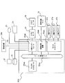
図3はかかる主制御部の構成とその制御の一具体例を示すブロック図であって、20aは主制御部、20aaはマイクロコンピュータ、20abはモータコントローラ、20acは画像処理装置、20adは外部インターフェース、20aeはデータ通信バス、20bは副制御部、21はUSB(ユニバーサル・シリアル・バス)メモリ、22はハードディスク、23はモニタ、24はキーボード、25はレギュレータ、26はバルブユニット、27aは塗布ヘッド部移動用Y軸リニアモータ用ドライバ、27bはガントリ移動用X軸リニアモータ用ドライバ、27cはテーブル回転用θ軸モータ用ドライバ、28は画像認識カメラ、29は通信ケーブルである。
FIG. 3 is a block diagram showing a configuration of the main control unit and a specific example of the control. 20a is a main control unit, 20aa is a microcomputer, 20ab is a motor controller, 20ac is an image processing apparatus, and 20ad is an external interface. , 20ae is a data communication bus, 20b is a sub-control unit, 21 is a USB (Universal Serial Bus) memory, 22 is a hard disk, 23 is a monitor, 24 is a keyboard, 25 is a regulator, 26 is a valve unit, and 27a is a coating head. Y-axis linear motor driver for moving
同図において、主制御部20aは、マイクロコンピュータ20aa、Y軸方向移動機構11を駆動する塗布ヘッド部移動用Y軸リニアモータ用ドライバ(以下、Y軸ドライバと略称する)27aやX軸方向移動機構6a,6bを駆動するガントリ移動用X軸リニアモータ用ドライバ(以下、X軸ドライバと略称する)27b,基板が搭載された基板保持機構8(図1)をθ軸方向に駆動するテーブル回転用θ軸モータ用ドライバ(以下、θ軸ドライバと略称する)27cを制御するモータコントローラ20ab、画像認識カメラ28で得られる画像信号を処理する画像処理装置20ac及び副制御部20bや塗布ヘッド部10のペースト塗布動作を制御するレギュレータ25,バルブユニット26と通信を行なう外部インターフェース20adを内蔵しており、これらマイクロコンピュータ20aaとモータコントローラ20abと画像処理装置20acと外部インターフェース20adとがデータ通信バス20aeを介して相互に接続されている。ここで、副制御部20bは、この外部インターフェース20adに通信ケーブル29を介して接続されている。
In the figure, a
マイクロコンピュータ20aaには、図示しないが、主演算部や後述する塗布描画を行なうための処理プログラムを格納したROM,主演算部での処理結果や外部インターフェース20ad,モータコントローラ20abからの入力データを格納するRAM,外部インターフェース20adやモータコントローラ20abとデータをやりとりする入出力部などを備えている。 The microcomputer 20aa, although not shown, ROM that stores a processing program for performing a coating rendering the main operating unit or later, the processing result or the external interface 20 ad of the main operation unit, the input data from the motor controller 20ab A RAM for storing, an input / output unit for exchanging data with the external interface 20ad and the motor controller 20ab, and the like are provided.
これらY軸ドライバ27aで駆動される各塗布ヘッド部10のY軸方向移動機構11としてのリニアモータやX軸ドライバ27bで駆動されるガントリ2a,2bのX軸方向移動機構6a,6bとしてのリニアモータは、各塗布ヘッド部10やガントリ2a,2bの位置を検出するリニアスケールを検出するエンコーダが内蔵されており、その検出結果を夫々Y軸ドライバ27a,X軸ドライバ27bに供給して塗布ヘッド部10のX軸方向,Y軸方向の位置制御が行なわれる。また、同様にして、θ軸ドライバ27cで駆動される基板保持機構8(図1)においても基板の回転量を検出するエンコーダが内蔵されており、その検出結果をθ軸ドライバ27cに供給して基板の向きの制御が行なわれる。
Linear motors as the X-axis direction moving mechanisms 6a and 6b of the gantry 2a and 2b driven by the linear motor as the Y-axis direction moving mechanism 11 of each coating head unit 10 driven by the Y-
主制御部20aと副制御部20bとの連携した制御のもと、各モータ(リニアモータやZ軸サーボモータ,θ軸サーボモータ)が、キーボード24(図3)から入力されてマイクロコンピュータ20aaのRAMに格納されているデータに基いて移動・回転することにより、基板保持機構8(図1)に保持されている基板19(図2)を、X軸方向に任意の距離だけ移動させ、かつ、ノズル17(図2)を上下に移動するZ軸移動テーブル14を介して、支持したノズル17を、横梁2a,2bに設けられた塗布ヘッド部10のY軸方向移動機構11により、Y軸方向に任意の距離を移動し、その移動中、ペースト収納筒15に設定した気圧が継続して印加されてノズル17の先端部の吐出口からペーストが吐出され、基板19に所望のペーストパターンが描画される。
Each motor (linear motor, Z-axis servo motor, θ-axis servo motor) is input from the keyboard 24 (FIG. 3) under the control of the
同図において、架台1(図6)側に設けられている架台側支持部材5bはスライダ30bからなるものであって、このスライダ30bは磁石板7とともにX軸方向移動機構6bを構成するリニアモータ備えており、磁石板7とこれに平行に設置されているガイドレール7bとに沿って移動することができる。そして、このスライダ30bの平坦な上面が載置面30b1をなしている。なお、個のスライダ30bは、架台1の架台側面1bから突出しないように、設置されている。 In this figure, the gantry-side support member 5b provided on the gantry 1 (FIG. 6) side is composed of a slider 30b. The slider 30b together with the magnet plate 7 constitutes a linear motor that constitutes the X-axis direction moving mechanism 6b. It provided and can be moved along the guide rail 7 b which is installed parallel to the magnet plate 7 thereto. The flat upper surface of the slider 30b forms a mounting surface 30b1. The individual sliders 30 b are installed so as not to protrude from the gantry side surface 1 b of the gantry 1.
図8は図6に示す状態から図1に示す状態にするための作業の流れの一具体例を示すフローチャートである。以下では、ガントリ2bを例にして説明するが、ガントリ2aについても同様である。 FIG. 8 is a flowchart showing a specific example of a work flow for changing from the state shown in FIG. 6 to the state shown in FIG. Hereinafter, will be explained with the gantry 2b as an example, Ru similarly der applies gantry 2a.
図9は図1に示す状態から図6に示す状態にするための作業の流れの一具体例を示すフローチャートである。以下では、ガントリ2bを例にして説明するが、ガントリ2aについても同様である。 FIG. 9 is a flowchart showing a specific example of a work flow for changing from the state shown in FIG. 1 to the state shown in FIG. Hereinafter, will be explained with the gantry 2b as an example, Ru similarly der applies gantry 2a.
同図において、まず、ガントリ2bと架台1との接続部の配線及び配管の接続を取り外し(ステップS300)、持ち上げ用治具をガントリ2bに取り付ける(ステップS301)。しかる後、図7で説明したように、締結ボルト35をL字型金具31b及びスライダ30bから取り外し(ステップS302)、持ち上げ用治具によってガントリ2bを持ち上げて(ステップS303)、別の場所に移動させる(ステップS304)。これにより、ガンドリ2bが架台1から分離される。 In the figure, first, the wiring and piping connection of the connecting portion between the gantry 2b and the gantry 1 are removed (step S300), and the lifting jig is attached to the gantry 2b (step S301). Thereafter, as described in FIG. 7, the fastening bolt 35 is removed from the L -shaped bracket 31b and the slider 30b (step S302), the gantry 2b is lifted by the lifting jig (step S303), and moved to another location. (Step S304). As a result, the gantry 2 b is separated from the gantry 1.
図10は図1に示すペースト塗布装置のガントリ2a,2bを架台1から取り外した状態の他の具体例を示す斜視図であって、図6に対応図部分には同一符号を付けて重複する説明を省略する。 Figure 10 is a perspective view showing another specific example of being detached gantry 2a of paste application apparatus shown in FIG. 1 and 2b from rack stand 1, overlapping with the same reference numerals to the corresponding diagram parts in FIG. 6 Description to be omitted is omitted.
同図において、架台側支持部材5bは、図7に示すスライダ30b上に図7に示すL字型金具31bが一体に搭載された構成をなしており、このL字型金具31bの垂直部の外面が当接面36をなしている。かかる当接面36は、架台1の側面1bに、そこから突出しない程度に、近接して配置される。 In the figure, the gantry-side supporting member 5b is, L-shaped bracket 31b shown in FIG. 7 on slider 30b shown in FIG. 7 has no configuration mounted integrally, the vertical portion of the L-shaped brackets 31b The abutment surface 36 is formed on the outer surface. Such abutment surface 36, the side surface 1b of the base 1, so as not to leave collision therefrom, are arranged close to.
以上は、ガントリ2aに関するものであったが、他方のガントリ5aについても同様である。 The above description relates to the gantry 2a , but the same applies to the other gantry 5a.
なお、図12でも、図1と同様、この図面が煩雑となることを避けるために、図面上に現われている部分にのみ符号を付け、それ以外の部分については、符号を省略している。また、この第2の実施形態は、基板面上にペーストパターン(シール材パターン)を描画するペースト塗布装置及び方法に関するものとするものであるが、基板上に液晶を滴下する滴下装置にも適用できることは言うまでもない。 Even 1 2, similarly to FIG. 1, in order to avoid that this drawing is complicated, with the code only partially appearing in the drawings, for the other portions are omitted code . The second embodiment relates to a paste application apparatus and method for drawing a paste pattern (seal material pattern) on a substrate surface, but is also applicable to a dropping apparatus for dropping liquid crystal on a substrate. Needless to say, you can.
1 架台
1a,1b 架台側面
2a,2b ガントリ(門型フレーム)
3a,3b 横梁
4a,4b 横梁側支持部材
5a,5b 架台側支持部材
6a,6b X軸方向移動機構
7 磁石板
7a,7b ガイドレール
8 基板保持機構
9 ヘッド設置面
10 塗布ヘッド部
11 Y軸方向移動機構
12 Z軸サーボモータ
13 Z軸移動テ−ブル支持ブラケット
14 Z軸移動テーブル
30a,30b スライダ
31a,31b L字型金具
30b1 載置面
31b1 当接面
31b2 上面
32,33 ボルト孔
34a,34b リブ
35 締結ボルト
31b3 頂面
36,37 当接面
38 突出部
39 ボルト孔
40a,40b X軸方向移動機構設置面
1 frame 1a, 1b frame side 2a, 2b gantry (gate frame)
3a, 3b transverse beam 4a, 4b transverse beam side support member 5a, 5b gantry side support member 6a, 6b X axis direction movement mechanism 7 magnet plate 7a, 7b guide rail 8 substrate holding mechanism 9 head installation surface 10 coating head part 11 Y axis direction Moving mechanism 12 Z-axis servo motor 13 Z-axis moving table support bracket 14 Z-axis moving table 30a, 30b Slider 31a, 31b L-shaped bracket 30b1 Mounting surface 31b1 Abutting surface 31b2 Upper surface 32, 33 Bolt hole 34a, 34b rib 35 fastening bolts
3 1b3 Top surface 36, 37 Contact surface 38 Projection 39 Bolt hole 40a, 40b X axis direction moving mechanism installation surface
Claims (6)
該架台上の基板載置テーブルの外側に該ガントリの移動機構を設け、
該ガントリの移動機構に該ガントリを締結ボルトで固定するガントリ取り付け手段を設け、
該ガントリの大きさは、該ガントリの両端部が該架台の側面から突出する大きさであって、該塗布ヘッドは該基板の上部を外れた位置まで移動することを特徴とするペースト塗布装置。 An application head for discharging paste from the nozzle outlet is installed on the vertical side surface of the gantry, the application head moves in the longitudinal direction of the gantry , and the gantry is installed on the gantry and installed on the gantry. In the paste application device in which the gantry moves relative to the substrate placed on the substrate placement table, and the paste is ejected onto the substrate from the nozzle ejection port.
Provide a moving mechanism of the gantry on the outside of the substrate mounting table on the gantry,
Provided gantry attachment means to affix the gantry moving mechanism of the gantry fastening bolt,
The size of the gantry is such that both end portions of the gantry protrude from the side surface of the gantry, and the coating head moves to a position off the top of the substrate .
該架台上の該基板載置テーブルよりも下側に該ガントリの移動機構を設け、
該ガントリの移動機構に該ガントリを締結ボルトで固定するガントリ取り付け手段を設け、
該ガントリの大きさは、該ガントリの両端部が該架台の側面から突出する大きさであって、該塗布ヘッドは該基板の上部を外れた位置まで移動することを特徴とするペースト塗布装置。 An application head for discharging paste from the nozzle outlet is installed on the vertical side surface of the gantry, the application head moves in the longitudinal direction of the gantry , and the gantry is installed on the gantry and installed on the gantry. In the paste application device in which the gantry moves relative to the substrate placed on the substrate placement table, and the paste is ejected onto the substrate from the nozzle ejection port.
A mechanism for moving the gantry below the substrate mounting table on the gantry;
Provided gantry attachment means to affix the gantry moving mechanism of the gantry fastening bolt,
The size of the gantry is such that both end portions of the gantry protrude from the side surface of the gantry, and the coating head moves to a position off the top of the substrate .
前記ガントリの移動機構および前記ガントリ取り付け手段は、前記基板載置テーブルよりも低い位置に設けたことを特徴とするペースト塗布装置。 In the paste application device according to claim 1,
The paste applying apparatus, wherein the gantry moving mechanism and the gantry attaching means are provided at a position lower than the substrate mounting table.
該架台上の該基板載置テーブルの外側に該ガントリの移動機構を設けて該ガントリを移動させ、
該ガントリの移動機構で該ガントリについての該ガントリの移動機構からの取り外し、並びに該ガントリの移動機構への取り付けを締結ボルトによって行なうガントリ取り付け手段を含む構成とし、
該ガントリの大きさは、該ガントリの両端部が該架台の側面から突出する大きさであって、該塗布ヘッドは該基板の上部を外れた位置まで移動する特徴とするペースト塗布方法。 An application head for discharging paste from the nozzle outlet is installed on the vertical side surface of the gantry, the application head moves in the longitudinal direction of the gantry , and the gantry is installed on the gantry and installed on the gantry. In the paste application method in which the gantry moves with respect to the substrate placed on the substrate placement table and the paste is ejected onto the substrate from the nozzle ejection port.
The gantry is moved by providing a moving mechanism of the gantry on the outside of the substrate mounting table on the gantry,
Removal from the moving mechanism of the gantry about the gantry moving mechanism of the gantry, as well as a structure comprising a gantry attachment means for attachment to the moving mechanism of the gantry by a fastening bolt,
The size of the gantry is such that both end portions of the gantry protrude from the side surface of the gantry, and the coating head moves to a position off the top of the substrate .
該架台上の該基板載置テーブルよりも下側に該ガントリの移動機構を設けて該ガントリを移動させ、
該ガントリの移動機構で該ガントリについての該ガントリの移動機構からの取り外し、並びに該ガントリの移動機構への取り付けを締結ボルトによって行なうガントリ取り付け手段を含む構成とし、
該ガントリの大きさは、該ガントリの両端部が該架台の側面から突出する大きさであって、該塗布ヘッドは該基板の上部を外れた位置まで移動することを特徴とするペースト塗布方法。 An application head for discharging paste from the nozzle outlet is installed on the vertical side surface of the gantry, the application head moves in the longitudinal direction of the gantry , and the gantry is installed on the gantry and installed on the gantry. In the paste application method in which the gantry moves with respect to the substrate placed on the substrate placement table and the paste is ejected onto the substrate from the nozzle ejection port.
A gantry moving mechanism is provided below the substrate mounting table on the gantry to move the gantry,
Removal from the moving mechanism of the gantry about the gantry moving mechanism of the gantry, as well as a structure comprising a gantry attachment means for attachment to the moving mechanism of the gantry by a fastening bolt,
The size of the gantry is such that both end portions of the gantry protrude from the side surface of the gantry, and the coating head moves to a position off the top of the substrate .
前記ガントリの移動機構および前記ガントリ取り付け手段は、前記基板載置テーブルよりも低い位置に設けられていることを特徴とするペースト塗布方法。 The paste application method according to claim 4,
The paste application method, wherein the gantry moving mechanism and the gantry attaching means are provided at a position lower than the substrate mounting table.
Priority Applications (4)
| Application Number | Priority Date | Filing Date | Title |
|---|---|---|---|
| JP2009109843A JP5550255B2 (en) | 2009-04-28 | 2009-04-28 | Paste coating apparatus and coating method |
| KR1020100016121A KR101139043B1 (en) | 2009-04-28 | 2010-02-23 | Paste applying device and applying method |
| CN2010101261829A CN101875535B (en) | 2009-04-28 | 2010-02-24 | Pasting device and pasting method |
| TW099105503A TWI455761B (en) | 2009-04-28 | 2010-02-25 | Paste coating device and coating method |
Applications Claiming Priority (1)
| Application Number | Priority Date | Filing Date | Title |
|---|---|---|---|
| JP2009109843A JP5550255B2 (en) | 2009-04-28 | 2009-04-28 | Paste coating apparatus and coating method |
Publications (3)
| Publication Number | Publication Date |
|---|---|
| JP2010253446A JP2010253446A (en) | 2010-11-11 |
| JP2010253446A5 true JP2010253446A5 (en) | 2012-04-05 |
| JP5550255B2 JP5550255B2 (en) | 2014-07-16 |
Family
ID=43018230
Family Applications (1)
| Application Number | Title | Priority Date | Filing Date |
|---|---|---|---|
| JP2009109843A Active JP5550255B2 (en) | 2009-04-28 | 2009-04-28 | Paste coating apparatus and coating method |
Country Status (4)
| Country | Link |
|---|---|
| JP (1) | JP5550255B2 (en) |
| KR (1) | KR101139043B1 (en) |
| CN (1) | CN101875535B (en) |
| TW (1) | TWI455761B (en) |
Families Citing this family (2)
| Publication number | Priority date | Publication date | Assignee | Title |
|---|---|---|---|---|
| DE102019207185A1 (en) * | 2019-05-16 | 2020-11-19 | Siemens Aktiengesellschaft | Printing device and method for printing an object |
| CN112623700A (en) * | 2020-12-04 | 2021-04-09 | 深圳市韩安特科技有限公司 | Display screen maintenance equipment |
Family Cites Families (12)
| Publication number | Priority date | Publication date | Assignee | Title |
|---|---|---|---|---|
| JPH05329728A (en) * | 1992-05-29 | 1993-12-14 | Mitsubishi Heavy Ind Ltd | Cutting machine |
| JP2002200450A (en) * | 2000-12-28 | 2002-07-16 | Chugai Ro Co Ltd | Non-contact movable table coater |
| JP3793727B2 (en) * | 2002-02-04 | 2006-07-05 | 株式会社 日立インダストリイズ | Paste applicator |
| JP2003229055A (en) * | 2002-02-05 | 2003-08-15 | Tatsumo Kk | Phosphor layer filling device and filling method for plasma display panel |
| CN101326625B (en) * | 2006-03-06 | 2010-04-21 | 株式会社爱发科 | Stage unit |
| KR100746304B1 (en) | 2006-08-10 | 2007-08-03 | 주식회사 탑 엔지니어링 | Dispenser for flat panel display |
| KR20080051607A (en) * | 2006-12-06 | 2008-06-11 | 엘지디스플레이 주식회사 | Dispensing apparatus |
| JP2008221444A (en) * | 2007-03-15 | 2008-09-25 | Danaher Motion Japan Kk | Gantry type xy stage |
| JP4328364B2 (en) * | 2007-03-27 | 2009-09-09 | 住友重機械工業株式会社 | Stage equipment |
| JP2008238144A (en) * | 2007-03-29 | 2008-10-09 | Toray Eng Co Ltd | Apparatus and method for applying coating liquid |
| CN101663098B (en) * | 2007-04-23 | 2013-02-27 | 武藏工业株式会社 | Working apparatus, and cover for the working apparatus |
| DE102007020779B3 (en) * | 2007-05-03 | 2008-12-18 | Siemens Ag | Automatic placement machine for loading electrical and / or optical components on substrates |
-
2009
- 2009-04-28 JP JP2009109843A patent/JP5550255B2/en active Active
-
2010
- 2010-02-23 KR KR1020100016121A patent/KR101139043B1/en active IP Right Grant
- 2010-02-24 CN CN2010101261829A patent/CN101875535B/en not_active Expired - Fee Related
- 2010-02-25 TW TW099105503A patent/TWI455761B/en active
Similar Documents
| Publication | Publication Date | Title |
|---|---|---|
| TWI659782B (en) | Operating device and method with position correction function | |
| JP4911761B2 (en) | Deformable gantry working device | |
| KR101099240B1 (en) | Carrier type conveying apparatus, and conveying and assembling method of the same | |
| US7880873B2 (en) | Droplet discharge device | |
| KR20040078063A (en) | PASTE APPLICATlON APPARATUS AND METHOD | |
| US7222926B2 (en) | Droplet jetting apparatus, an electro-optical apparatus, a method of manufacturing an electro-optical apparatus, and an electronic device | |
| US20200179972A1 (en) | Application system, operation system, and posture changing unit | |
| KR20070041391A (en) | Paste coating apparatus | |
| JP2010253446A5 (en) | ||
| JP5550255B2 (en) | Paste coating apparatus and coating method | |
| JP5525182B2 (en) | Paste coating apparatus and coating method | |
| KR20110028787A (en) | Paste dispenser and method for applying paste | |
| JP2007245033A (en) | Paste coating device | |
| JP4478656B2 (en) | Paste application method | |
| EP2806720B1 (en) | Printed board working apparatus | |
| KR20110061270A (en) | Device adjusting the gap between nozzle and printing-object of inkjet printer and printing method using the same | |
| JP4870410B2 (en) | Paste applicator | |
| JP5326520B2 (en) | Drawing apparatus and method of attaching head to head unit in drawing apparatus | |
| KR100649963B1 (en) | Head unit of paste dispenser | |
| JP4085700B2 (en) | Paste applicator | |
| JPH1190303A (en) | Paste applying machine | |
| KR20170080980A (en) | Paste dispenser | |
| US20240083112A1 (en) | Three-dimensional object printing apparatus and control method | |
| JP4989199B2 (en) | Electronic component mounting device | |
| JP5044332B2 (en) | Processing equipment |