JP2010222002A - Attaching/detaching structure of main member of bicycle - Google Patents
Attaching/detaching structure of main member of bicycle Download PDFInfo
- Publication number
- JP2010222002A JP2010222002A JP2010105182A JP2010105182A JP2010222002A JP 2010222002 A JP2010222002 A JP 2010222002A JP 2010105182 A JP2010105182 A JP 2010105182A JP 2010105182 A JP2010105182 A JP 2010105182A JP 2010222002 A JP2010222002 A JP 2010222002A
- Authority
- JP
- Japan
- Prior art keywords
- bicycle
- fitted
- crank
- main member
- concavo
- Prior art date
- Legal status (The legal status is an assumption and is not a legal conclusion. Google has not performed a legal analysis and makes no representation as to the accuracy of the status listed.)
- Pending
Links
Images


Abstract
Description
本発明は、自転車のペダルが装着されるクランクを、自転車の本体側に対して着脱可能に構成し、前記クランクと前記本体側とは特定の嵌合構造とすることによって、特定の組み合わせ以外のクランクと本体側とは嵌合できないように構成して、盗難防止効果が得られる技術に関するものである。 In the present invention, a crank to which a bicycle pedal is attached is configured to be detachable with respect to the bicycle body side, and the crank and the body side have a specific fitting structure, so that other than a specific combination. The present invention relates to a technique for preventing theft by configuring the crank and the main body so that they cannot be fitted.
従来より、自転車の盗難を防止するためには、固定式の錠やチェーン式の錠を取り付けておき、前記錠に対応する特定の鍵を持った人や、前記錠に設定された暗証番号を知る人だけが開錠して利用できるようにしている。 Conventionally, in order to prevent theft of a bicycle, a fixed lock or a chain lock is attached, and a person with a specific key corresponding to the lock or a password set on the lock is assigned. Only people who know it can unlock it and use it.
しかし、このような錠は、工具などを用いて破壊したり開錠することが可能であり、破壊したり開錠すれば、自転車は普通に利用することが可能な状態となるため、根本的な盗難防止策ではなかった。 However, such a lock can be broken or unlocked with a tool, etc., and if it is broken or unlocked, the bicycle can be used normally. It was not an anti-theft measure.
また、盗難防止対策とは別の技術であるが、特許文献1に示したように、運搬時に邪魔になるペダルを着脱する構造や、クランクの交換を容易にするための構造が知られている。このような構造の自転車の場合には、自転車を置いて離れる場合には、ペダルやクランクを取り外して携行すれば、他人が前記自転車を勝手に使用しようとしても、ペダルやクランクが無いため、譜鬱には使用できないので、若干の盗難防止効果は得られるかも知れないが。しかし、ペダルやクランクは同種類の自転車であれば、部品の互換性を確保するために共通規格で製造されていることが多く、手持ちの別のペダルやクランクを取り付けると、容易に自転車として利用できるようになるので、効果的な盗難防止策ではない。
Moreover, although it is a technique different from anti-theft measures, as shown in
そこで、本発明は、持ち主が近くにいない自転車を、仮に錠を破壊したり開錠することができても、その自転車を普通に使用することが実質的に不可能とする構造を提供することを目的としてなされたものである。
Therefore, the present invention provides a structure that makes it impossible to use the bicycle normally even if the bicycle whose owner is not nearby can be broken or unlocked. It was made for the purpose.
本発明の請求項1に係る自転車の主要部材の着脱構造は、
自転車の本体に形成した嵌合部と主要部材に形成した被嵌合部と当接させて嵌合することが可能であって、また、前記嵌合部と前記被嵌合部とを分離させて離脱することが可能であるように構成し、
前記本体の嵌合部と前記主要部材の被嵌合部とは、互いに対応した凹凸構造を備え、
前記凹凸構造は、自転車の個体ごと個別の構造として、
異なる個体の主要部材の被嵌合部とは対応せず嵌合できないように構成して、盗難を防止できるように構成した。
請求項2では、
前記主要部材は、クランクであり、
前記本体側の嵌合部は、スプロケットホイールの回転筒の側面に位置し、
前記主要部材側の被嵌合部は、前記クランクの軸の側面に位置したものである。
請求項3では、
前記主要部材は、ペダルであり、
前記本体側の嵌合部は、クランクの端部の側面に位置し、
前記主要部材側の被嵌合部は、前記ペダルの軸の側面に位置したものである。
The attachment / detachment structure of the main member of the bicycle according to
The fitting portion formed on the main body of the bicycle and the fitted portion formed on the main member can be brought into contact with each other and fitted, and the fitting portion and the fitted portion are separated from each other. Configured to be able to leave
The fitting portion of the main body and the fitted portion of the main member have a concavo-convex structure corresponding to each other,
The uneven structure is an individual structure for each individual bicycle,
It was constructed so that it could not be fitted and could not be fitted with the fitted parts of the main members of different individuals, so that theft could be prevented.
In claim 2,
The main member is a crank;
The fitting portion on the main body side is located on the side surface of the rotating cylinder of the sprocket wheel,
The fitted portion on the main member side is located on the side surface of the crank shaft.
In
The main member is a pedal,
The fitting portion on the main body side is located on the side surface of the end portion of the crank,
The fitted portion on the main member side is located on the side surface of the pedal shaft.
請求項1に係る自転車の主要部材の着脱構造では、
自転車の本体に形成した嵌合部と主要部材に形成した被嵌合部と当接させて嵌合することが可能であって、また、前記嵌合部と前記被嵌合部とを分離させて離脱することが可能であるように構成し、
前記本体の嵌合部と前記主要部材の被嵌合部とは、互いに対応した凹凸構造を備え、
前記凹凸構造は、自転車の個体ごと個別の構造として、
異なる個体の主要部材の被嵌合部とは対応せず嵌合できないように構成したので、
当該自転車の持ち主が、自転車から離れるときに、前記主要部材を本体から分離させて携行すれば、
他人が、当該自転車を持ち主に無断で勝手に使用しようとしても、前記主要部材が無いので自転車として普通に使用することができない。
したがって、当該自転車は盗難されるおそれが少なくなり、盗難防止効果が得られる。
また、仮に、同一種類の自転車用の主要部品を持参したとしても、前記着脱構造は、特定の主要部品でなれば嵌合できないので、そのような場合でも盗難防止効果が得られる。
In the bicycle detachable structure according to
The fitting portion formed on the main body of the bicycle and the fitted portion formed on the main member can be brought into contact with each other and fitted, and the fitting portion and the fitted portion are separated from each other. Configured to be able to leave
The fitting portion of the main body and the fitted portion of the main member have a concavo-convex structure corresponding to each other,
The uneven structure is an individual structure for each individual bicycle,
Since it is configured so that it does not correspond to the mating part of the main member of a different individual and can not be fitted,
If the owner of the bicycle leaves the bicycle and carries the main member separated from the main body,
Even if another person tries to use the bicycle without permission from the owner, the bicycle cannot be normally used as a bicycle because there is no main member.
Accordingly, the bicycle is less likely to be stolen and an anti-theft effect can be obtained.
Even if the same kind of bicycle main parts are brought, the attachment / detachment structure cannot be fitted unless it is a specific main part. Therefore, even in such a case, an antitheft effect can be obtained.
請求項2に係る発明では、
前記主要部材は、クランクであるので、
当該自転車の持ち主が、自転車から離れるときに、前記クランクを本体から分離させて携行すれば、
他人が、当該自転車を持ち主に無断で勝手に使用しようとしても、前記クランクが無いので自転車として普通に使用することができない。
したがって、当該自転車は盗難されるおそれが少なくなり、盗難防止効果が得られる。 請求項3に係る発明では、
前記主要部材は、ペダルであるので、
当該自転車の持ち主が、自転車から離れるときに、前記ペダルを本体から分離させて携行すれば、
他人が、当該自転車を持ち主に無断で勝手に使用しようとしても、前記ペダルが無いので自転車として普通に使用することができない。
したがって、当該自転車は盗難されるおそれが少なくなり、盗難防止効果が得られる。
In the invention according to claim 2,
Since the main member is a crank,
When the owner of the bicycle leaves the bicycle and carries the crank separated from the main body,
Even if another person tries to use the bicycle without permission from the owner, it cannot be used normally as a bicycle because there is no crank.
Accordingly, the bicycle is less likely to be stolen and an anti-theft effect can be obtained. In the invention according to
Since the main member is a pedal,
When the owner of the bicycle leaves the bicycle and carries the pedal separately from the main body,
Even if another person tries to use the bicycle without permission from the owner, the bicycle cannot be used normally because there is no pedal.
Accordingly, the bicycle is less likely to be stolen and an anti-theft effect can be obtained.
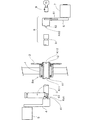
本発明に係る自転車の主要部材の着脱構造の要部の断面を示した図1において、
BBは、自転車のフレームの下部に配設されたボトムブラケット部であり、このボトムブラケット部BBには回転筒1がベアリングを用いて回転自在に挿通されている。前記回転筒1の一方の端面にはスプロケットホイール2が一体に固定されており、このスプロケットホイール2にはチェーン(省略)が掛け回されており、前記スプロケットホイール2に与えられた駆動力が、当該自転車の後輪に伝達されるように構成されている。
In FIG. 1 which showed the cross section of the principal part of the attachment or detachment structure of the main member of the bicycle which concerns on this invention,
BB is a bottom bracket portion disposed at the lower part of the frame of the bicycle, and the rotating
前記回転筒1の一方の端面の嵌合部11には特定の凹凸構造K11が形成され、他方の端面の嵌合部12には前記凹凸構造とは異なる別の凹凸構造K12が形成されている。なお、両面の特定構造は同じにすることもできる。
A specific concavo-convex structure K11 is formed in the
3は回転軸であり、前記回転筒1の内部に挿通され得るように構成されている。
前記回転軸3の一方の端部には、1つのクランク4の一端が連結され、このクランク4の他端には1つのペダル5が回転自在に取り付けられている。
図示したように、前記クランク4は、前記回転軸3に対して折り畳み可能に連結されているとよい。
前記クランク4の根元であって、使用状態において前記回転筒1の嵌合部11と当接する面の被嵌合部41には、図2に示したように、前記特定の凹凸構造K11に対応した特定の凹凸構造K41が形成されている。
前記回転軸3の他方の端部には、他の1つのクランク6の一端を着脱することが可能であり、このクランク6の他端には他の1つのペダル7が回転自在に取り付けられている。
前記クランク6の根元であって、使用状態において前記回転筒1の嵌合部12と当接する面の被嵌合部62には、前記特定の凹凸構造K12に対応した特定の凹凸構造K62が形成されている。
One end of one
As illustrated, the
As shown in FIG. 2, the fitted
One end of another
A specific concavo-convex structure K62 corresponding to the specific concavo-convex structure K12 is formed in the fitted
前記回転軸3の他方の端部の周面には円弧状もしくは円周状の溝31が形成されており、前記クランク6を装着した状態において、前記クランク6の一端には、前記溝31に嵌まり込むように構成された抜け止め部材61が嵌脱可能に配設されている。この抜け止め部材61を前記溝31から離脱させると、前記クランク6は前記回転軸3から引き抜くことができ、前記クランク6を前記回転軸3の端部に差し込んだ状態で、前記抜け止め部材61を前記溝31に嵌め込ませると、前記クランク6は前記回転軸3から引き抜くことができない係合状態に固定される。前記溝31と前記抜け止め部材61とで、抜け止め構造8が形成されている。
An arcuate or
前記抜け止め構造8の一例を、図3を参照して説明する。
前記抜け止め構造8を構成する抜け止め部材61は、前記クランク6の回転軸側の一端に、支持軸81によって回動可能に支持され、さらに、バネ82によって、前記抜け止め部材61の先端が前記回転軸側に付勢して設けられている。
前記抜け止め部材61の操作部に力を加えて前記バネ82に抗して押し下げると、先端が回転軸3の溝31から離れて、前記操作部への力を除くと前記バネ82の弾性復元力によって前記抜け止め部材61の先端は前記回転軸3の溝31に嵌まり込む。
このようにして、前記抜け止め部材61と前記溝31による抜け止め構造8が構成されている。
An example of the retaining
A retaining
When a force is applied to the operating portion of the retaining
In this way, the retaining
前記回転筒1に、前記回転軸3を差し込んで、前記回転軸3の一方の端部ではクランク4を前記回転軸3と直交する状態にセットし、前記回転軸3の他方の端部にはクランク6を差し込んで、前記回転軸3と直交する状態にセットし、前記抜け止め構造8によってクランク6が抜けないような状態にすると、
前記クランク4の凹凸構造K41は、前記回転筒1の端面の凹凸構造K11と対応する凹凸構造であるため、互いに嵌合して一体的に連結された状態となる。
また、前記クランク6の凹凸構造K62は、前記回転筒1の端面の凹凸構造K12と対応する凹凸構造であるため、互いに嵌合して一体的に連結された状態となる。
The
Since the concavo-convex structure K41 of the
Further, since the concavo-convex structure K62 of the
以上のような、嵌合による結合状態において、前記2つのペダル5、7を交互に踏み込むと、前記ペダル5に加えられた力は前記クランク4を介して前記凹凸構造K41に伝達され、前記凹凸構造K41に伝達された力は、嵌合構造によって空回り等で滑ることなく前記凹凸構造K11に伝達され、前記回転筒1に伝達される。
また、前記ペダル7に加えられた力は前記クランク6を介して前記凹凸構造K62に伝達され、前記凹凸構造K62に伝達された力は、嵌合構造によって空回り等で滑ることなく前記凹凸構造K12に伝達され、前記回転筒1に伝達される。
このようにして、2つのクランク5、7を介して加えられた力によって、前記回転筒1を回転させ、前記回転筒1に固定されたスプロケットホイール2が回転駆動され、さらに、チェーンを介して後輪を回転させて、当該自転車を進ませることができるのである。
When the two
Further, the force applied to the pedal 7 is transmitted to the concavo-convex structure K62 via the
In this way, the
以上の説明は、当該自転車を使用する場合の手順と動作を説明したものであるが、以下においては、持ち主が当該自転車から離れる場合の手順を説明する。
自転車を置いて自転車から離れる場合には、通常は鍵を掛けるだけであるが、それだけでは盗難の心配があるので、本発明に係る自転車の主要部材の着脱構造を備えた自転車の場合には、主要部材であるクランクを取り外してカバンやバッグ等に入れて携行する。前記クランクの取り外しは、前記抜け止め構造8の前記抜け止め部材61の一部を前記溝31から引き抜いて係合状態を解除するだけで簡単である。
なお、前記クランク6と回転軸3との連結部分は、折り畳み軸63を中心にして折り畳み可能とすることによって、さらに携行しやすい大きさとなる。
また、取り外したクランク類を収納するための収納袋を用意するとよい。
The above description describes the procedure and operation when the bicycle is used. In the following, the procedure when the owner leaves the bicycle will be described.
When putting a bicycle away from the bicycle, it is usually only a lock, but with that alone, there is a risk of theft, so in the case of a bicycle equipped with a structure for attaching and detaching the main member of the bicycle according to the present invention, Remove the main crank and put it in a bag or bag. The crank can be easily removed by simply pulling out a part of the retaining
The connecting portion between the
A storage bag for storing the removed cranks may be prepared.
次に、以上のようにしてクランクを取り外して携行した場合の、盗難防止効果を説明する。
高価な自転車が駅前等の路上に置いてあった場合には、盗難の危険性が高くなる。しかし、その自転車にクランクが付いていなかった場合には、仮に盗んだとしても容易には、自転車として使用することが困難であることが明らかである。
なぜなら、その自転車に使用できるクランクを用意するためには、その自転車の回転筒に形成された凹凸構造を精密に測定して、それに対応する凹凸構造を加工したクランクを製造する必要があるからである。
仮に、同じ種類の自転車を所有している者が、自分の自転車用のクランクを装着しようとしても、他の自転車では凹凸構造が一致しないため役に立たないので、盗むことを諦めることになる。
このようにして、本発明による自転車の主要部材の着脱構造によれば、クランクを取り外して身に携行することで、クランクのついていない自転車では役に立たないので、その自転車が盗難されることを防止することができるのである。
また、盗難防止効果だけでなく、邪魔なパダル類を取り外すことができるので整理も容易になるという効果も得られる。
Next, the anti-theft effect when the crank is removed and carried as described above will be described.
If expensive bicycles are placed on the streets in front of the station, the risk of theft increases. However, if the bicycle does not have a crank, it is apparent that it is difficult to use it as a bicycle even if it is stolen.
This is because in order to prepare a crank that can be used for the bicycle, it is necessary to precisely measure the uneven structure formed on the rotating cylinder of the bicycle and to manufacture a crank with a corresponding uneven structure. is there.
Even if a person who owns the same type of bicycle tries to put on a crank for his / her bicycle, it will not be useful for other bicycles because the uneven structure does not match, so he will give up stealing.
In this way, according to the bicycle main member attachment / detachment structure according to the present invention, by removing the crank and carrying it to the body, it is not useful for a bicycle without a crank, so that the bicycle is prevented from being stolen. It can be done.
Moreover, not only the anti-theft effect but also the effect of facilitating the arrangement can be obtained because the disturbing padals can be removed.
実施例1の場合は、図1、2に示したように、主要部材として、両方のクランクを着脱可能に構成して、それぞれの嵌合部と被嵌合部に対応する凹凸構造を設けたが、片方のクランクだけ着脱可能に構成しても、盗難防止効果が得られる。 In the case of Example 1, as shown in FIGS. 1 and 2, both the cranks are configured to be detachable as the main members, and the concavo-convex structure corresponding to each fitting portion and the fitted portion is provided. However, even if only one crank is detachable, an anti-theft effect can be obtained.
本発明に用いられる凹凸構造について、以下に詳細に説明する。
実施例1の場合には、回転筒1の端面に凹凸構造K11,K12を形成し、クランクの側面に、前記凹凸構造K11,K12と対応する凹凸が形成された凹凸構造K41,K62を形成したものである。
なお、本発明において、対応する凹凸構造とは、一方の部材が凸構造の部分に対して、他方の部材は凹構造に形成し、両者が嵌合した状態では、対応する凹凸構造が互いに嵌まりあって滑らない状態で結合される構造を言う。
かかる凹凸構造の例としては、図2に示したように、一方の部材に例えば2箇所の凹構造を形成し、他方の部材には前記2箇所の凹構造に嵌まり合う形状と大きさと位置で凸構造を形成した。なお、凹凸が逆でもよいことは当然である。
このような凹凸構造は、形状、大きさ、位置の何れか1つでも異なれば、互いに嵌まり合うことができないので、膨大な種類の組み合わせが可能となり、製造販売する自転車の全ての凹凸構造を、実質的に異なる凹凸構造とすることが可能であり、互換性の無い主要部材を構成することが可能となる。したがって、前記凹凸構造が、互換性がなく、互いに単一の組み合わせである錠と鍵との関係となって、盗難防止効果が得られるのである。
The uneven structure used in the present invention will be described in detail below.
In the case of Example 1, the concavo-convex structures K11 and K12 are formed on the end face of the
In the present invention, the corresponding concavo-convex structure means that one member has a convex structure and the other member has a concave structure. A structure that is joined in a state that does not slip.
As an example of such a concavo-convex structure, as shown in FIG. 2, for example, two concave structures are formed on one member, and the shape, size, and position of the other member are fitted to the two concave structures. A convex structure was formed. Of course, the unevenness may be reversed.
Such concavo-convex structures cannot be fitted to each other if they are different in any one of shape, size, and position, so a huge variety of combinations are possible, and all concavo-convex structures of bicycles to be manufactured and sold can be obtained. Therefore, it is possible to form substantially different concavo-convex structures, and it is possible to constitute incompatible main members. Therefore, the concavo-convex structure is incompatible and has a relationship between a lock and a key which are a single combination with each other, and an anti-theft effect can be obtained.
なお、前記主要部材としてのクランクを取り外して携行することを忘れた場合には、他人に取り外されて持ち去られるという危険性があるので、そのようなおそれがある場合には、前記クランクの着脱部分に、図示したように、従来のシリンダー錠等の盗難防止構造9を備えるとよい。
Note that if you forget to remove and carry the crank as the main member, there is a risk that it will be removed and carried away by someone else. Moreover, as shown in the figure, it is preferable to provide a theft prevention structure 9 such as a conventional cylinder lock.
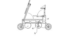
また、実施例2としては、図4に示したように、特殊な2枚のパネルを用いてフレームFを構成し、前後の車輪や、ハンドルポスト、シートポストを、矢印のように折り畳んで前記フレーム内に主要部分を格納可能に構成してもよい。
実施例2の場合のハンドルは、ネジを緩めてハンドルバーをハンドルポストに対して左右の一方にスライドさせた後に回転させて、ハンドルバーとハンドルポストをほぼ平行にした状態で、前記フレームに格納する。
なお、軽量化のために前記パネル状のフレームには、強度を損なわない範囲で多数の打ち抜き部を設けるとよい。また、前記打ち抜き部は、所有者の名前やイニシャル文字を打ち抜き加工すると、所有者の満足度が高まるとともに、名前が大暑された自転車を盗む者は少なくなり、その点でも盗難防止効果が得られる。
このように構成した折り畳み自転車の場合には、車輪や、ハンドル、シートをフレーム内に格納しても、ペダル5やクランク4がフレームFから突出して邪魔になるが、本発明の自転車の主要部材の着脱構造を採用することによって、クランクを取り外せば、自転車の主要部分はフレーム内に格納された状態となり、少ない収納スペースに収納可能となるので、自動車のトランクや車内に、複数台でも収納できるようになる。
また、図3に示したような特殊な自転車の場合には、自動車のトランクや車内に収納しない場合でも、駅前等の屋外の路上に放置すると、盗難に合いやすいが、フレームをチェーンロック等で建物に固定し、さらに、クランクを取り外しておけば、盗難に合う危険性が少なくなる。
In addition, as shown in FIG. 4, the frame F is configured by using two special panels as shown in FIG. 4, and the front and rear wheels, the handle post, and the seat post are folded as shown by arrows. You may comprise so that a main part can be stored in a flame | frame.
The handle in the case of Example 2 is stored in the frame with the screw loosened and the handle bar slid to one of the left and right with respect to the handle post and then rotated so that the handle bar and the handle post are substantially parallel. To do.
In order to reduce the weight, the panel-like frame may be provided with a number of punched portions as long as the strength is not impaired. In addition, when the punching part punches and processes the owner's name and initial characters, the satisfaction of the owner is increased, and the number of people who steal bicycles whose names are overheated is reduced. .
In the case of the folding bicycle configured as described above, even if the wheel, the handle, and the seat are stored in the frame, the
Also, in the case of a special bicycle as shown in FIG. 3, even if it is not stored in the trunk of the car or in the car, it can easily be stolen if left on the road in front of the station, etc. If it is fixed to the building and the crank is removed, the risk of being stolen is reduced.
また、実施例3としては、クランクの代わりにペダルを主要部材としてもよい。
この場合は、携行する主要部材がクランクの場合より小さいので携行しやすい。この場合も、両方のペダルではなく片方のペダルを着脱可能に構成してもある程度の盗難防止効果が得られる。
In the third embodiment, a pedal may be used as a main member instead of the crank.
In this case, since the main member to carry is smaller than the case of a crank, it is easy to carry. In this case as well, a certain degree of theft prevention effect can be obtained even if one pedal is configured to be detachable instead of both pedals.
実施例4としては、主要部材をシートポストやハンドルポストとして、それらの装着部に対応した凹凸構造を形成してもよい。 As Example 4, the main member may be a seat post or a handle post, and a concavo-convex structure corresponding to the mounting portion thereof may be formed.
また、嵌合部と被嵌合部を設ける位置は、本体側の側面と主要部材側の側面に限定されるものではなく、着脱可能であって、嵌合させた場合に力が伝達される位置であればどこでもよい。例えば、一方の部材を他方に被せる構造として、前記一方の部材の内面に凹凸構造を設け、他方の週面に対応する凹凸構造を設けてもよい。
Further, the positions where the fitting portion and the fitted portion are provided are not limited to the side surface on the main body side and the side surface on the main member side, and are detachable, and force is transmitted when they are fitted. It can be anywhere. For example, as a structure in which one member is covered with the other, an uneven structure may be provided on the inner surface of the one member, and an uneven structure corresponding to the other week surface may be provided.
BB 自転車の本体のボトムブラケット部
1 回転筒
11、12 嵌合部
4、6 主要部材、クランク
41、62 被嵌合部
KK11,K12 凹凸構造
2 スプロケットホイール
4 回転筒
K42,K62 凹凸構造
5、7 ペダル
8 抜け止め構造
BB Bicycle
Claims (3)
前記本体の嵌合部と前記主要部材の被嵌合部とは、互いに対応した凹凸構造を備え、
前記凹凸構造は、自転車の個体ごと個別の構造として、
異なる個体の主要部材の被嵌合部とは対応せず嵌合できないように構成して、盗難を防止できるように構成したことを特徴とする自転車の主要部材の着脱構造。 The fitting portion formed on the main body of the bicycle and the fitted portion formed on the main member can be brought into contact with each other and fitted, and the fitting portion and the fitted portion are separated from each other. Configured to be able to leave
The fitting portion of the main body and the fitted portion of the main member have a concavo-convex structure corresponding to each other,
The uneven structure is an individual structure for each individual bicycle,
A structure for attaching and detaching a main member of a bicycle, characterized in that the main member of a different individual does not correspond to the fitted portion of the main member and cannot be fitted to prevent theft.
前記本体側の嵌合部は、スプロケットの軸の側面に位置し、
前記主要部材側の被嵌合部は、前記クランクの軸の側面に位置したことを特徴とする請求項1に記載の自転車の主要部材の着脱構造。 The main member is a crank;
The fitting portion on the main body side is located on the side surface of the sprocket shaft,
2. The bicycle main member attaching / detaching structure according to claim 1, wherein the fitted portion on the main member side is located on a side surface of the shaft of the crank.
前記本体側の嵌合部は、クランクの端部の側面に位置し、
前記主要部材側の被嵌合部は、前記ペダルの軸の側面に位置したことを特徴とする請求項1に記載の自転車の主要部材の着脱構造。 The main member is a pedal,
The fitting portion on the main body side is located on the side surface of the end portion of the crank,
2. The bicycle main member attaching / detaching structure according to claim 1, wherein the fitted portion on the main member side is located on a side surface of the shaft of the pedal.
Priority Applications (1)
| Application Number | Priority Date | Filing Date | Title |
|---|---|---|---|
| JP2010105182A JP2010222002A (en) | 2010-04-30 | 2010-04-30 | Attaching/detaching structure of main member of bicycle |
Applications Claiming Priority (1)
| Application Number | Priority Date | Filing Date | Title |
|---|---|---|---|
| JP2010105182A JP2010222002A (en) | 2010-04-30 | 2010-04-30 | Attaching/detaching structure of main member of bicycle |
Publications (1)
| Publication Number | Publication Date |
|---|---|
| JP2010222002A true JP2010222002A (en) | 2010-10-07 |
Family
ID=43039632
Family Applications (1)
| Application Number | Title | Priority Date | Filing Date |
|---|---|---|---|
| JP2010105182A Pending JP2010222002A (en) | 2010-04-30 | 2010-04-30 | Attaching/detaching structure of main member of bicycle |
Country Status (1)
| Country | Link |
|---|---|
| JP (1) | JP2010222002A (en) |
Cited By (3)
| Publication number | Priority date | Publication date | Assignee | Title |
|---|---|---|---|---|
| JP2012166706A (en) * | 2011-02-15 | 2012-09-06 | Hisanori Nanba | Foldable bicycle |
| IT201700015699A1 (en) * | 2017-02-13 | 2018-08-13 | Campagnolo Srl | Bicycle bottom bracket member, as well as pedal crank assembly and bottom bracket assembly comprising such a shaft member |
| JP2021011253A (en) * | 2019-07-09 | 2021-02-04 | アイデス株式会社 | Crank attachment/detachment structure for bicycle and bicycle including the same |
Citations (5)
| Publication number | Priority date | Publication date | Assignee | Title |
|---|---|---|---|---|
| JPH10119852A (en) * | 1996-10-18 | 1998-05-12 | Akuteibu Hanbai:Kk | Burglar prevention device for bicycle |
| JP2001506555A (en) * | 1996-12-12 | 2001-05-22 | アドフラ ソチエタ レスポンサビリタ リミテ | Vehicle anti-theft device with torsional grip / throttle control device |
| JP2003312576A (en) * | 2002-04-09 | 2003-11-06 | Campagnolo Spa | Bicycle component having coupling portion and coupling thereof |
| JP2007253919A (en) * | 2006-03-24 | 2007-10-04 | Yuji Hagiwara | Detachable pedal |
| JP2010089591A (en) * | 2008-10-07 | 2010-04-22 | Kansai Sincere Co Ltd | Theft preventing device for motorcycle |
-
2010
- 2010-04-30 JP JP2010105182A patent/JP2010222002A/en active Pending
Patent Citations (5)
| Publication number | Priority date | Publication date | Assignee | Title |
|---|---|---|---|---|
| JPH10119852A (en) * | 1996-10-18 | 1998-05-12 | Akuteibu Hanbai:Kk | Burglar prevention device for bicycle |
| JP2001506555A (en) * | 1996-12-12 | 2001-05-22 | アドフラ ソチエタ レスポンサビリタ リミテ | Vehicle anti-theft device with torsional grip / throttle control device |
| JP2003312576A (en) * | 2002-04-09 | 2003-11-06 | Campagnolo Spa | Bicycle component having coupling portion and coupling thereof |
| JP2007253919A (en) * | 2006-03-24 | 2007-10-04 | Yuji Hagiwara | Detachable pedal |
| JP2010089591A (en) * | 2008-10-07 | 2010-04-22 | Kansai Sincere Co Ltd | Theft preventing device for motorcycle |
Cited By (5)
| Publication number | Priority date | Publication date | Assignee | Title |
|---|---|---|---|---|
| JP2012166706A (en) * | 2011-02-15 | 2012-09-06 | Hisanori Nanba | Foldable bicycle |
| IT201700015699A1 (en) * | 2017-02-13 | 2018-08-13 | Campagnolo Srl | Bicycle bottom bracket member, as well as pedal crank assembly and bottom bracket assembly comprising such a shaft member |
| EP3360768A1 (en) * | 2017-02-13 | 2018-08-15 | Campagnolo S.r.l. | Shaft element of a bicycle bottom bracket, as well as crank arm assembly and bottom bracket assembly comprising such a shaft element |
| JP2021011253A (en) * | 2019-07-09 | 2021-02-04 | アイデス株式会社 | Crank attachment/detachment structure for bicycle and bicycle including the same |
| JP7411222B2 (en) | 2019-07-09 | 2024-01-11 | アイデス株式会社 | A bicycle crank attachment/detachment structure and a bicycle equipped with the attachment/detachment structure |
Similar Documents
| Publication | Publication Date | Title |
|---|---|---|
| US7316302B2 (en) | Motorcycle disk-brake lock | |
| CA2470242C (en) | Disk-brake lock for a motorcycle | |
| JP2010222002A (en) | Attaching/detaching structure of main member of bicycle | |
| TW201420423A (en) | A bicycle pedal with locking function | |
| DE602004015080D1 (en) | THEFT PROTECTION DEVICE FOR BICYCLE HANDLEBAR | |
| DE602005003566D1 (en) | CYLINDER LOCK WITH A CODED KEY FOR LOCKING THE STEERING WHEEL AND PROTECTING THE VEHICLE BEFORE THEFT | |
| JP2005170363A (en) | Theft preventive device for bicycle | |
| WO2009057105A1 (en) | Locking method, system and kit for a motorcycle | |
| KR101503477B1 (en) | A Locking means for a bike | |
| JP2007106335A (en) | Two-wheeler | |
| US6976374B1 (en) | Vehicle pedal lock | |
| CN201291937Y (en) | Anti-theft locking device of vehicle | |
| JP3084607U (en) | Bicycle escape prevention device | |
| JP3147189U (en) | Motorcycle anti-theft shift pedal unit | |
| JP3496988B2 (en) | bicycle | |
| DK2949553T3 (en) | PEDAL TRANSFORMABLE TO THEFT PROTECTION | |
| JP2005193877A (en) | Anti-theft lever for motorcycle | |
| US20110283828A1 (en) | Bicycle Pedal With Increased Theft Protection | |
| JP5632551B1 (en) | Bicycle brake equipment | |
| JP3111124U (en) | Mooring anchor for motorcycle antitheft with cover | |
| WO2019092589A2 (en) | Universal dual-purpose lock for motorcycle | |
| JP3002668U (en) | Car anti-theft device | |
| JP3080214U (en) | Car anti-theft device | |
| TWI254682B (en) | Motorcycle handle with burglarproof device | |
| JP2001213371A (en) | Stand lock interlocking type lock for bicycle |
Legal Events
| Date | Code | Title | Description |
|---|---|---|---|
| A621 | Written request for application examination |
Effective date: 20110118 Free format text: JAPANESE INTERMEDIATE CODE: A621 |
|
| A977 | Report on retrieval |
Free format text: JAPANESE INTERMEDIATE CODE: A971007 Effective date: 20120629 |
|
| A131 | Notification of reasons for refusal |
Free format text: JAPANESE INTERMEDIATE CODE: A131 Effective date: 20120710 |
|
| A02 | Decision of refusal |
Free format text: JAPANESE INTERMEDIATE CODE: A02 Effective date: 20121106 |