JP2010193886A - Cutting strand - Google Patents
Cutting strand Download PDFInfo
- Publication number
- JP2010193886A JP2010193886A JP2010037205A JP2010037205A JP2010193886A JP 2010193886 A JP2010193886 A JP 2010193886A JP 2010037205 A JP2010037205 A JP 2010037205A JP 2010037205 A JP2010037205 A JP 2010037205A JP 2010193886 A JP2010193886 A JP 2010193886A
- Authority
- JP
- Japan
- Prior art keywords
- strand
- circular cutter
- strands
- cutting device
- processing industry
- Prior art date
- Legal status (The legal status is an assumption and is not a legal conclusion. Google has not performed a legal analysis and makes no representation as to the accuracy of the status listed.)
- Withdrawn
Links
Images


Classifications
-
- A—HUMAN NECESSITIES
- A24—TOBACCO; CIGARS; CIGARETTES; SIMULATED SMOKING DEVICES; SMOKERS' REQUISITES
- A24C—MACHINES FOR MAKING CIGARS OR CIGARETTES
- A24C5/00—Making cigarettes; Making tipping materials for, or attaching filters or mouthpieces to, cigars or cigarettes
- A24C5/14—Machines of the continuous-rod type
- A24C5/28—Cutting-off the tobacco rod
-
- A—HUMAN NECESSITIES
- A24—TOBACCO; CIGARS; CIGARETTES; SIMULATED SMOKING DEVICES; SMOKERS' REQUISITES
- A24C—MACHINES FOR MAKING CIGARS OR CIGARETTES
- A24C5/00—Making cigarettes; Making tipping materials for, or attaching filters or mouthpieces to, cigars or cigarettes
- A24C5/14—Machines of the continuous-rod type
- A24C5/31—Machines of the continuous-rod type with special arrangements coming into operation during starting, slowing-down or breakdown of the machine, e.g. for diverting or breaking the continuous rod
Abstract
Description
本発明は、回転軸を中心として回転可能な円形カッタを有するタバコ加工産業のストランド切断装置に関する。更に本発明は、回転する円形カッタが、ストランドガイド軌道内を移動するストランドを通るように案内される、タバコ加工産業の少なくとも1つのストランドを切断するための方法に関する。 The present invention relates to a strand cutting device in the tobacco processing industry having a circular cutter rotatable about a rotation axis. The invention further relates to a method for cutting at least one strand of the tobacco processing industry, wherein a rotating circular cutter is guided through a strand moving in a strand guide track.
相応のストランド切断装置は、特許文献1から公知である。円形カッタの回転軸は、円形カッタが通過可能なストランドに対して横に位置し、回転軸は、ストランド切断装置の作動中、本質的に水平に配設され、ストランド切断装置は、ストランドと円形カッタを噛み合せるために、スイングアームを介して水平に旋回される。 A corresponding strand cutting device is known from US Pat. The rotational axis of the circular cutter is located transverse to the strand through which the circular cutter can pass, the rotational axis being arranged essentially horizontally during operation of the strand cutting device, and the strand cutting device is circular with the strand. To engage the cutter, it is swung horizontally through a swing arm.
本発明の課題は、確実かつ迅速なストランドの切断が可能であり、ストランドが、切断時に、特にその軌道外に方向を変えられず、綺麗な切断が可能であるように、タバコ加工産業の前記形式のストランド切断装置と、タバコ加工産業のストランドを切断するための相応の方法を発展させることにある。更に、本発明によるストランド切断装置は、複数のストランド、特に2つのストランドを処理する機械でも適用可能であるべきである。 The problem of the present invention is that the strands of the tobacco processing industry can be surely and quickly cut, and that the strands can be cleanly cut when they are cut, in particular the direction of the strands is not changed. It is to develop a type of strand cutting device and a corresponding method for cutting strands in the tobacco processing industry. Furthermore, the strand cutting device according to the invention should also be applicable in machines that process multiple strands, in particular two strands.
この課題は、円形カッタを作動時に直線的に移動させる円形カッタガイド装置が設けられていることを特徴とする、回転軸を中心として回転可能な円形カッタを有するタバコ加工産業のストランド切断装置によって解決される。円形カッタガイド装置は、特に、ストローク装置及び/又は直動装置として形成されている。 This problem is solved by a strand cutting device in the tobacco processing industry having a circular cutter rotatable about a rotation axis, characterized in that a circular cutter guide device is provided for linearly moving the circular cutter during operation. Is done. The circular cutter guide device is in particular formed as a stroke device and / or a linear motion device.
作動中の円形カッタの直線運動により、非常に限定的な円形カッタによるストランドのイ切断が可能である。特に、回転軸は、ストランド切断装置の作動中、本質的に水平に配設されている。特に、回転軸は、ストランドガイド軌道の長手方向軸に対して垂直に形成されている。ストランドガイド軌道は、本発明の範囲内で、ストランドが移動する軌道である。この場合、必ずしも強制ガイドを設ける必要はない。ストランドガイド軌道は、自由区間を介して、特に空気中を、通る。 Due to the linear motion of the circular cutter in operation, it is possible to cut the strands with a very limited circular cutter. In particular, the rotating shaft is arranged essentially horizontally during operation of the strand cutting device. In particular, the rotation axis is formed perpendicular to the longitudinal axis of the strand guide track. A strand guide track is a track in which a strand moves within the scope of the present invention. In this case, it is not always necessary to provide a forced guide. The strand guide track passes through the free section, in particular in the air.
特に、円形カッタガイド装置は、円形カッタの回転軸に対して平行な回転カッタの移動を生じさせる。選択的又は付加的に、ストランドガイド軌道に対して本質的に垂直なもしくはタバコ加工産業の切断すべき移動可能なストランドに対して横の円形カッタの移動が可能になる。円形カッタガイド装置は、直線移動を生じさせる油圧シリンダか、例えば相応のギヤユニットを介して円形カッタの移動を可能にするモータを備えることができる。この場合、円形カッタガイド装置により、1つのストランド又は複数のストランドを通るように切断するために十分な大きさの円形カッタのための相応のストロークが得られる。 In particular, the circular cutter guide device causes movement of the rotary cutter parallel to the rotational axis of the circular cutter. As an alternative or in addition, it is possible to move the circular cutter transversely to the movable strand to be cut essentially perpendicular to the strand guide track or in the tobacco processing industry. The circular cutter guide device can be equipped with a hydraulic cylinder that causes linear movement or a motor that allows movement of the circular cutter via a corresponding gear unit, for example. In this case, the circular cutter guide device provides a corresponding stroke for a circular cutter large enough to cut through one strand or multiple strands.
特に、円形カッタの回転軸は、ストランドガイド軌道もしくは円形カッタの作動中に切断すべきストランドに対して横に、特に垂直に配設されている。この場合、円形カッタは、直線的に、特に垂直に、ストランドを通るように案内される。 In particular, the rotational axis of the circular cutter is arranged transversely, in particular perpendicularly to the strand to be cut during operation of the strand guide track or circular cutter. In this case, the circular cutter is guided through the strands in a straight line, in particular vertically.
特に下から、ストランド又はストランドガイド軌道に向かって移動可能、特に旋回可能、又は直線的に移動可能なストランドガイド装置が設けられている。ストランドガイド装置は、特に、一種のサイジング装置の延長部又は補完部であり、ストランドガイド装置は、ストランドが移動可能な相応の複数の開口を備える。これら開口は、特にサイジング装置の開口と整列可能である。ストランドガイド装置は、特に円形カッタのためのエンドサポートとして使用される。ストランドガイド装置は、特に、互いに平行に配設された移動可能なストランドを収容可能な2つのガイド開口を備える。 In particular, from below, a strand guide device is provided which is movable towards the strand or the strand guide track, in particular pivotable or linearly movable. The strand guide device is in particular an extension or complement of a kind of sizing device, which comprises a corresponding plurality of openings through which the strand can move. These openings are in particular alignable with the openings of the sizing device. The strand guide device is used in particular as an end support for circular cutters. The strand guide device comprises in particular two guide openings which can accommodate movable strands arranged parallel to each other.
円形カッタは、特に、円形カッタガイド装置によって、タバコ加工産業の平行な2つのストランド又は平行な2つのストランドガイド軌道の間隔よりも大きい直線ストロークを受ける。この間隔は、本発明の範囲内で、ストランドの外側の面からストランドの外側の面を意味するので、ストロークは、2つのストランドを越える。 Circular cutters, in particular, are subjected to a linear stroke greater than the interval between two parallel strands or two parallel strand guide tracks in the tobacco processing industry by means of a circular cutter guide device. This spacing means within the scope of the invention from the outer surface of the strand to the outer surface of the strand, so that the stroke exceeds two strands.
円形カッタは、特にその切断エッジが、波又は歯の付いた表面を有する。 A circular cutter has a waved or toothed surface, especially at its cutting edge.
特に、円形カッタの回転軸は、タバコ加工産業の移動可能な切断すべきストランドに対して85°〜90°の角度である及び/又は円形カッタの直線移動に対して0°〜5°の角度である。選択的に、相応のストランドガイド軌道に対して85°〜90°の角度であってもよい。ストランドガイド軌道もしくはストランドに対する円形カッタの回転軸の角度が、90°付近にある場合、もしくはちょうど90°である場合が、好ましい。その場合、これは、ストランドの相対的に長い斜めの切断を行なう。この切断を短くするため、特にストランド速度が高い場合、円形カッタは、数度だけ調整することができるので、ストランド速度が高い場合の切断は、改善される。 In particular, the rotational axis of the circular cutter is an angle of 85 ° to 90 ° with respect to the movable strand to be cut in the tobacco processing industry and / or an angle of 0 ° to 5 ° with respect to the linear movement of the circular cutter. It is. Optionally, the angle may be between 85 ° and 90 ° with respect to the corresponding strand guide track. It is preferable that the angle of the rotation axis of the circular cutter with respect to the strand guide track or the strand is in the vicinity of 90 °, or just 90 °. In that case, this makes a relatively long oblique cut of the strand. In order to shorten this cut, especially when the strand speed is high, the circular cutter can be adjusted by a few degrees, so that the cut when the strand speed is high is improved.
特に、ストランド速度に依存してストランドガイド軌道に対する円形カッタの相応の角度を調整する制御装置が設けられている。円形カッタは、特に1000〜3000rpmの回転速度で回転され、2000rpmの場合が特に好ましい。ストランド速度は、通常50〜100m/minの範囲内であり、切断箇所は、12〜20mmの長さを備える。 In particular, a control device is provided for adjusting the corresponding angle of the circular cutter relative to the strand guide track depending on the strand speed. The circular cutter is particularly rotated at a rotational speed of 1000 to 3000 rpm, and 2000 rpm is particularly preferable. The strand speed is usually in the range of 50 to 100 m / min, and the cut portion has a length of 12 to 20 mm.
課題は、更に、ストランド製造機の始動させるために、ストランド切断装置が、ストランド製造機のストランド製造運転中の位置とは違う位置に配設されており、両位置の間に、ストランドガイド軌道が配設されていることを特徴とする、タバコ加工産業の少なくとも1つのストランドを切断するための本発明によるストランド切断装置を有するタバコ加工産業のストランド製造機によって解決される。 Further, the problem is that, in order to start the strand manufacturing machine, the strand cutting device is disposed at a position different from the position during the strand manufacturing operation of the strand manufacturing machine, and the strand guide track is located between the two positions. It is solved by a strand making machine of the tobacco processing industry having a strand cutting device according to the invention for cutting at least one strand of the tobacco processing industry, characterized in that it is arranged.
ツインストランド又はマルチストランド製造機の場合、2つのストランドもしくは複数のストランドが、2つの位置の間に配設されている。これにより、非常に限定及びコントロールされたストランド製造機の始動及び停止が可能である。 In the case of a twin-strand or multi-strand maker, two strands or multiple strands are disposed between the two positions. This allows very limited and controlled starting and stopping of the strand making machine.
ストランド製造機を始動させるため、ストランド製造機は、低いストランド生産速度から高いストランド生産速度にされ、この場合、先ず、ストランドが排出され、従って、次処理のために使用されない。満足のいくストランドもしくは所定のストランドが得られてから、次に、1つのストランド、又はツインストランド製造機又はマルチストランド製造機の場合には複数のストランドが、本発明による装置により切断される。次いで、ストランドの上流の部分が、しかも比較的上流で切断され、ストランド製造機の通常の次処理に達し、相応に所望の長さに切断され、次処理により例えばフィルタシガレットが得られる。ストランドは、フィルタストランド又はシガレットストランドである。 To start the strand maker, the strand maker is brought from a low strand production rate to a high strand production rate, in which case the strands are first discharged and are therefore not used for further processing. Once a satisfactory strand or a given strand has been obtained, then a single strand or, in the case of a twin-strand maker or a multi-strand maker, a plurality of strands are cut by the device according to the invention. The upstream part of the strand is then cut relatively upstream, reaching the normal next processing of the strand making machine, and correspondingly cut to the desired length, and for example a filter cigarette is obtained. The strand is a filter strand or a cigarette strand.
課題は、更に、円形カッタが、直線的にストランドを通るように案内されることを特徴とする、回転する円形カッタが、ストランドガイド軌道内を移動するストランドを通るように案内される、タバコ加工産業の少なくとも1つのストランドを切断するための方法によって解決される。特に、円形カッタの直線移動は、ストランド長手方向軸に対して垂直である。直線移動により、非常に短いストロークで1つのストランドを切断すること、又は非常に短いストロークで複数のストランドを切断することができるので、非常に迅速な切断が可能である。この場合、装置は、非常にコンパクトな構成である。回転軸とストランド長手方向軸の間に、90°に等しくない角度を設けることができる。回転軸は、ストランド長手方向軸に対するその角度を顧慮して、特に旋回可能に形成されている。 The problem further is that the circular cutter is guided to pass through the strand moving linearly in the strand guide track, wherein the circular cutter is guided linearly through the strand. Solved by a method for cutting at least one strand of the industry. In particular, the linear movement of the circular cutter is perpendicular to the strand longitudinal axis. With linear movement, one strand can be cut with a very short stroke, or a plurality of strands can be cut with a very short stroke, so that a very quick cutting is possible. In this case, the device has a very compact configuration. An angle not equal to 90 ° can be provided between the axis of rotation and the longitudinal axis of the strand. The axis of rotation is particularly pivotable in view of its angle with respect to the longitudinal axis of the strand.
円形カッタの直線移動が、円形カッタの回転軸に対して平行である場合が、特に好ましい。 It is particularly preferred that the linear movement of the circular cutter is parallel to the rotational axis of the circular cutter.
特に、ストランドは、サポートとして使用されるストランドガイド装置に案内される。特に、ストランドガイド装置は、ストランドを切断するために、ストランドに向かって、特に上に向かって、移動される、特に旋回又は直線移動される。 In particular, the strands are guided to a strand guide device that is used as a support. In particular, the strand guide device is moved, in particular swiveled or linearly moved, towards the strands, in particular upwards, in order to cut the strands.
停止信号が生じた場合に、本発明による、タバコ加工産業の少なくとも1つのストランドを切断するための方法が実施されることを特徴とする、運転中のストランド製造機のコントロール式の停止をするための方法は、特に好ましい。この場合、停止信号は、例えば、ストランドの破損箇所が検出された場合に自動的に発生する信号でも、操作員によって発せられる信号でもよい。本発明による方法により、初めて、限定的にストランド材料を切断し、更に、限定的に切断の下流に位置する、切断されたストランド材料の次処理ステップを実施するように、運転中のストランド製造機のコントロール式の停止の実施が可能である。 In order to make a controlled stop of an operating strand production machine, characterized in that a method for cutting at least one strand of the tobacco processing industry according to the invention is carried out when a stop signal occurs This method is particularly preferable. In this case, the stop signal may be, for example, a signal that is automatically generated when a broken portion of the strand is detected or a signal that is issued by an operator. For the first time, the method according to the present invention cuts strand material in a limited way, and further carries out a subsequent processing step of the cut strand material, which is limitedly located downstream of the cut. It is possible to implement a controlled stop.
本発明を、以下で、一般的な発明思想を限定することなく、図面に関連させた実施例に基づいて説明する。この場合、文章で詳細には説明されていない全ての発明の詳細に関しては、図面を参照されたい。 The invention will now be described on the basis of embodiments associated with the drawings, without limiting the general inventive idea. In this case, reference is made to the drawings for all the details of the invention not described in detail in the text.
各図において、それぞれ同じ又は同じ形式の要素もしくは相応の部分は、同じ符号を備えるので、改めて説明することを省略する。 In each drawing, elements of the same or the same type or corresponding parts are provided with the same reference numerals, and will not be described again.
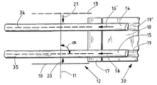
図1は、ストランド製造機30の一部の平面図を示す。これは、ツインストランド製造機、例えばツインフィルタストランド製造機、である。相応に、移送方向16,16’に移動する2つのフィルタストランド14及び15が図示されている。これは、被覆材料で被覆されたストランド14及び15である。フィルタストランド14及び15の被覆及び成形は、サイジング部で行なわれ、サイジング部の内、下側サイジング部材18が、ここでは図示されている。ストランド14及び15をガイドする相応のストランドガイド軌道19及び19’も図示されている。これは、下側サイジング部材18の領域内の相応に形成された軌道である。但し、ストランドガイド軌道19及び19’は、下側サイジング部材18の領域だけでなく、ストランドガイド装置17内にも延在し、図1の更に左側は、空気中を延在する。従って、本発明によるストランドガイド軌道19,19’は、特に、相応のストランドが配設されるもしくは移動される軌道である。これは、少なくとも部分的に、固定の制限部を使用しなくても可能である。
FIG. 1 shows a plan view of a part of the
ストランドを切断するため、図1には、回転軸11を中心として回転する円形カッタ10が図示されている。この円形カッタは、その切断エッジに波又は歯を設けてもよい。図1では、説明のために、始動位置12の下に操作員のための場所があり、運転位置13の上にストランド製造機の一部がある。図1の上の領域の、即ち位置13の上の、ストランド製造機に、例えばモータ、ギヤユニット等が配設されている。特に、そこには、ストランド14及び15を切断するために回転及びストロークさせるための回転カッタ用の駆動装置も配設されているが、図1には図示されていない。
In order to cut the strand, FIG. 1 shows a
円形カッタ10は、図1では、位置12、即ち始動位置、に存在する。回転軸11は、ストランド14及び15の長手方向軸34,35に対して垂直である。従って、角度αは、90°である。次処理に適したストランド14及び15が構成されると直ぐ、円形カッタ10は、位置12から矢印方向に、即ち円形カッタ移動方向20に、比較的迅速に両ストランド14及び15を通るように移動する。これにより、相応の切断部が、ストランド14及び15に生じる。切断部の上流に配設されたストランド14及び15の部分は、次処理に利用され、下流の部分は、次処理から除外される。その際、円形カッタ10は、運転位置13に達し、ストランド製造機が正常な生産運転をしている間、そこに留まる。
The
停止信号が発せられると直ぐ、円形カッタ10は、運転位置13から円形カッタ移動方向21にストランド14及び15を通って移動され、相応にストランド14及び15を切断する。その際、この切断部に対して相対的に上流のストランド14及び15の部分は、次処理から除外され、これに対して、切断部の下流の部分は、次処理をすることができる。これは、場合によっては設けられたセンサが、ストランドのこの部分がもはや次処理に適していないとのことを検知しないかぎり、行なわれる。
As soon as the stop signal is issued, the
ストランド14,15を安定させるため、ストランド14,15をガイドするための2つの開口25及び26を備えるストランドガイド装置17が設けられている。開口25,26は、図2及び3に良好に認められる。ストランドガイド装置17は、ストランドを切断するためにストランドの下からストランドに向かって移動もしくは旋回される。これも、図2及び3に良好に認められる。
In order to stabilize the
図2には、ハウジング23と円形カッタ10を備える本発明によるストランド切断装置22が、概略的に3次元図で図示されている。図2には、2つの開口25及び26を有するストランドガイド装置17が図示されている。ストランドガイド装置17は、図2では、ストランド14,15に向かって旋回され、図3ではストランド14,15から離れるように旋回されている。
In FIG. 2, a
図2には、始動時のストランド製造機の運転状態が図示されている。即ち、円形カッタ10は、図1の位置12に存在する。この位置は、機械壁24から離れているので、ストランド14,15は、円形カッタ10と機械壁24の間に配設されている。更に、図2と図3には、ストランド切断装置22の直線ストロークを可能にし、これにより円形カッタ10の直線ストロークを可能にするストローク装置27が示されている。
FIG. 2 shows the operating state of the strand manufacturing machine at the start. That is, the
更に、図2では、ストランドが下に向かって離されることが図示されており、これに対して図3では、ストランド製造機の正常な生産運転の状態で、ストランド14及び15が、ストランド製造機での次処理のために左に向かって案内されることが図示されている。正常な運転中、即ちストランド製造機の生産運転中、ストランドガイド装置17は、下に向かってストランド14及び15から離れるように移動もしくは旋回されている。
In addition, FIG. 2 illustrates that the strands are separated downward, whereas in FIG. 3, in the normal production operation of the strand making machine, the
図4には、ストランド製造機の一部のもう1つの別の概略平面図が図示されている。図4は、図1と比べて、ストランドガイド軌道19及び19’もしくはストランドガイド軌道19及び19’内に配設された図示されてないフィルタストランド14,15と同様に図示されてないストランド長手方向軸34,35に対して傾いた円形カッタ10を示す。回転軸34,35と円形カッタ移動方向20の間に、0°〜5°とすることができる角度βが記載されている。特に低速の場合は、角度βを大きくするか、0°ではなくすることに、意味がある。特に、角度βの制御は、ストランド速度に依存して行なわれる。
FIG. 4 illustrates another schematic plan view of another portion of the strand making machine. 4 is compared with FIG. 1 in the longitudinal direction of the strands not shown, as is the strand guide tracks 19 and 19 ′ or the
図面だけから読み取ることのできる前記全ての特徴と、他の特徴と組み合わせて開示されている個々の特徴は、単独でも、組み合わせても、本発明に重要であると見なされる。本発明による実施形は、個々の特徴又は複数の特徴の組み合わせによって得ることができる。 All of the features that can be read from the drawings alone and the individual features that are disclosed in combination with other features, alone or in combination, are considered important to the present invention. Embodiments according to the invention can be obtained by individual features or a combination of features.
10 円形カッタ
11 回転軸
12 始動位置
13 運転位置
14 フィルタストランド
15 フィルタストランド
16,16’ 移送方向
17 ストランドガイド装置
18 下側サイジング部材
19,19’ ストランドガイド軌道
20 円形カッタ移動方向
21 円形カッタ移動方向
22 ストランド切断装置
23 ハウジング
24 機械壁
25 開口
26 開口
27 ストローク装置
30 ストランド製造機
34 ストランド長手方向軸
35 ストランド長手方向軸
α 角度
β 角度
DESCRIPTION OF
Claims (14)
円形カッタ(10)を作動時に直線的に移動させる円形カッタガイド装置(27)が設けられていることを特徴とするストランド切断装置。 In a strand cutting device (22) of the tobacco processing industry having a circular cutter (10) rotatable about a rotation axis (11),
A strand cutting device comprising a circular cutter guide device (27) for linearly moving the circular cutter (10) during operation.
ストランド製造機の始動させるために、ストランド切断装置(22)が、ストランド製造機(30)のストランド製造運転中の位置(13)とは違う位置(12)に配設されており、両位置(12,13)の間に、少なくとも1つのストランドガイド軌道(19,19’)が配設されていることを特徴とするストランド製造機。 In a tobacco processing industry strand making machine (30) having a strand cutting device (22) according to any one of claims 1 to 7 for cutting at least one strand (14, 15) of the tobacco processing industry. ,
In order to start the strand manufacturing machine, the strand cutting device (22) is disposed at a position (12) different from the position (13) during the strand manufacturing operation of the strand manufacturing machine (30). 12. A strand manufacturing machine, characterized in that at least one strand guide track (19, 19 ′) is arranged between 12, 13).
円形カッタ(10)が、直線的にストランド(14,15)を通るように案内されることを特徴とする方法。 At least one strand (14, 15) in the tobacco processing industry, in which a rotating circular cutter (10) is guided through a strand (14, 15) moving in a strand guide track (19, 19 '). In the method for cutting,
A method characterized in that the circular cutter (10) is guided linearly through the strands (14, 15).
停止信号が生じた場合に、請求項9〜13のいずれか1つに記載の方法が実施されることを特徴とする方法。 In a method for a controlled shutdown of an operating strand production machine (30),
14. A method according to claim 9, wherein the method according to any one of claims 9 to 13 is carried out when a stop signal occurs.
Applications Claiming Priority (1)
| Application Number | Priority Date | Filing Date | Title |
|---|---|---|---|
| DE102009010090A DE102009010090A1 (en) | 2009-02-24 | 2009-02-24 | strand cutting |
Publications (2)
| Publication Number | Publication Date |
|---|---|
| JP2010193886A true JP2010193886A (en) | 2010-09-09 |
| JP2010193886A5 JP2010193886A5 (en) | 2013-03-14 |
Family
ID=42173045
Family Applications (1)
| Application Number | Title | Priority Date | Filing Date |
|---|---|---|---|
| JP2010037205A Withdrawn JP2010193886A (en) | 2009-02-24 | 2010-02-23 | Cutting strand |
Country Status (5)
| Country | Link |
|---|---|
| EP (1) | EP2220949B1 (en) |
| JP (1) | JP2010193886A (en) |
| CN (1) | CN101811308B (en) |
| DE (1) | DE102009010090A1 (en) |
| PL (1) | PL2220949T3 (en) |
Families Citing this family (1)
| Publication number | Priority date | Publication date | Assignee | Title |
|---|---|---|---|---|
| EP2729025A1 (en) * | 2011-07-07 | 2014-05-14 | Hauni Maschinenbau AG | Longitudinal conveying arrangement for products in the tobacco-processing industry |
Family Cites Families (14)
| Publication number | Priority date | Publication date | Assignee | Title |
|---|---|---|---|---|
| US1348057A (en) * | 1918-11-04 | 1920-07-27 | Comas Cigarette Machine Compan | Cutting attachment for cigarette-machines |
| GB321067A (en) * | 1928-11-10 | 1929-10-31 | American Mach & Foundry | Improvements in cut-off devices for cigarette making machines |
| GB1021741A (en) | 1963-05-20 | 1966-03-09 | Michael Aren Pym | Improvements in or relating to continuous rod making machines |
| US3380329A (en) * | 1966-04-06 | 1968-04-30 | Philip Morris Inc | Continuous rod cutter |
| DE2746915A1 (en) * | 1977-10-19 | 1979-04-26 | Hauni Werke Koerber & Co Kg | DEVICE FOR GUIDING TOOLS ON TOBACCO-PROCESSING MACHINERY |
| US4554931A (en) * | 1982-10-15 | 1985-11-26 | Hauni-Werke Korber & Co. Kg | Apparatus for severing rod-shaped articles of the tobacco processing industry |
| IT1208281B (en) * | 1987-04-17 | 1989-06-12 | Sasib Spa | BACO CUTTING DEVIATOR DEVICE IN CIGARETTES PACKAGING MACHINES |
| DE3813786C2 (en) | 1988-04-23 | 2000-02-17 | Hauni Werke Koerber & Co Kg | Device for cutting a strand of the tobacco processing industry |
| JP3274882B2 (en) * | 1992-05-08 | 2002-04-15 | 日本たばこ産業株式会社 | Tobacco rod travel guide device for cigarette making machine |
| IT1279717B1 (en) * | 1995-12-21 | 1997-12-16 | Gd Spa | CUTTING DEVICE FOR CONTINUOUS CIGARETTE BUGS |
| DE502004009212D1 (en) * | 2003-11-07 | 2009-05-07 | Hauni Maschinenbau Ag | Apparatus and method for producing at least two fiber strands of the tobacco processing industry |
| DE102005062644A1 (en) | 2005-12-23 | 2007-07-26 | Hauni Maschinenbau Ag | Cutting device and strand material removal device of the tobacco processing industry |
| DE102006042238A1 (en) * | 2006-09-06 | 2008-03-27 | Hauni Maschinenbau Ag | Device for conveying rod-shaped articles |
| ITBO20060664A1 (en) * | 2006-09-28 | 2006-12-28 | Gd Spa | CUTTING UNIT FOR AT LEAST ONE CONTINUOUS KISS |
-
2009
- 2009-02-24 DE DE102009010090A patent/DE102009010090A1/en not_active Ceased
-
2010
- 2010-02-03 EP EP10152474.2A patent/EP2220949B1/en active Active
- 2010-02-03 PL PL10152474T patent/PL2220949T3/en unknown
- 2010-02-23 JP JP2010037205A patent/JP2010193886A/en not_active Withdrawn
- 2010-02-24 CN CN201010136504.8A patent/CN101811308B/en active Active
Also Published As
| Publication number | Publication date |
|---|---|
| EP2220949B1 (en) | 2013-06-05 |
| DE102009010090A1 (en) | 2010-09-09 |
| EP2220949A1 (en) | 2010-08-25 |
| CN101811308B (en) | 2014-06-18 |
| CN101811308A (en) | 2010-08-25 |
| PL2220949T3 (en) | 2013-11-29 |
Similar Documents
| Publication | Publication Date | Title |
|---|---|---|
| JP4749100B2 (en) | Method and apparatus for cutting continuously fed bars into bar-shaped articles of varying length | |
| CN101505930B (en) | Machine for cutting paper logs | |
| JP4382082B2 (en) | Strand cutting device and strand material unloading device for tobacco processing industry | |
| JP2011510823A (en) | Pipe cutting device | |
| US8826785B2 (en) | Cutting machine | |
| US20120048078A1 (en) | Adjustable sickle blade head | |
| CN106393196A (en) | Slicing device for bletilla striata | |
| US20130025420A1 (en) | Method for the Slicing of Food Products | |
| JP2009136288A (en) | Strand cutting device | |
| JP5122300B2 (en) | Dough splitting device | |
| US20110167973A1 (en) | Apparatus and Method for Cutting Tubular Members | |
| JP2010193886A (en) | Cutting strand | |
| JP4554227B2 (en) | Continuous sheet cutting method | |
| JP5801198B2 (en) | Cutting device | |
| KR20170103783A (en) | A cutting device adapted to be placed above a gap extending across a carrying surface of a conveyor system | |
| EP1810798B1 (en) | Machine for cutting soap bars into portions of preset length, with flexible operation | |
| EP3243612B1 (en) | Cutting machine and method of cutting rolls of sheet material | |
| JP5730314B2 (en) | Cutting and grinding equipment | |
| JP2010193886A5 (en) | ||
| JP6099667B2 (en) | Method and apparatus for machining longitudinal edges of metal workpieces | |
| JP2003116513A (en) | Outfeed unit of tobacco production machine | |
| JP5430289B2 (en) | Cutting device | |
| JPS63232993A (en) | Device for cutting mass strand to unit piece | |
| KR101303891B1 (en) | Deburring machine having rotary type knife assembly | |
| JP2011130769A (en) | Cutting device, and cutting knife for cutting rod-like product in tobacco processing industry |
Legal Events
| Date | Code | Title | Description |
|---|---|---|---|
| RD04 | Notification of resignation of power of attorney |
Free format text: JAPANESE INTERMEDIATE CODE: A7424 Effective date: 20100604 |
|
| A521 | Written amendment |
Free format text: JAPANESE INTERMEDIATE CODE: A523 Effective date: 20130128 |
|
| A621 | Written request for application examination |
Free format text: JAPANESE INTERMEDIATE CODE: A621 Effective date: 20130128 |
|
| A761 | Written withdrawal of application |
Free format text: JAPANESE INTERMEDIATE CODE: A761 Effective date: 20130416 |