JP2010155061A6 - Hair dryer - Google Patents
Hair dryer Download PDFInfo
- Publication number
- JP2010155061A6 JP2010155061A6 JP2009220794A JP2009220794A JP2010155061A6 JP 2010155061 A6 JP2010155061 A6 JP 2010155061A6 JP 2009220794 A JP2009220794 A JP 2009220794A JP 2009220794 A JP2009220794 A JP 2009220794A JP 2010155061 A6 JP2010155061 A6 JP 2010155061A6
- Authority
- JP
- Japan
- Prior art keywords
- hair dryer
- dryer according
- switch
- fan
- button
- Prior art date
- Legal status (The legal status is an assumption and is not a legal conclusion. Google has not performed a legal analysis and makes no representation as to the accuracy of the status listed.)
- Pending
Links
Images


Abstract
【課題】シンプルで故障しないスイッチを有するヘアドライヤーを得る。
【解決手段】ファンとヒーターを有するヘアドライヤーに関する。ヘアドライヤーはプログラム可能な集積回路部(IC)が実装されたPCBボードを有し、また前記ファンとヒーターは前記PCBボードに接続される。複数のプリセットスイッチは、それぞれ単独で、又は任意の組み合わせでファンやヒーターの作動レベルを定める。PCBボードに接続された一つのマルチモードスイッチは、複数のプリセットスイッチを制御する。ユーザは、ヘアドライヤーを握っている手のみで、マルチモードスイッチを介して複数のプリセットスイッチを制御し、前記ヘアドライヤーを操作することができる。
【選択図】図1A hair dryer having a switch that is simple and does not fail is obtained.
The present invention relates to a hair dryer having a fan and a heater. The hair dryer has a PCB board on which a programmable integrated circuit part (IC) is mounted, and the fan and heater are connected to the PCB board. Each of the plurality of preset switches determines the operating level of the fan or heater alone or in any combination. One multi-mode switch connected to the PCB board controls a plurality of preset switches. The user can operate the hair dryer by controlling a plurality of preset switches via the multi-mode switch with only a hand holding the hair dryer.
[Selection] Figure 1
Description
本発明は,電気製品に関する。特に、本発明は電気加熱式のヘアドライヤーに関する。 The present invention relates to an electrical product. In particular, the present invention relates to an electrically heated hair dryer.
電気加熱式のヘアドライヤーは魅力的な機能を提供しながら様々な形状のものが市販されている。バリエーションに関係なく、市販されている電気加熱式のヘアドライヤーは、通常の操作のための二以上の別個のボタン又はスイッチ、又はボタンとスイッチの組み合わせから構成されている。 Various types of electric heating hair dryers are commercially available while providing attractive functions. Regardless of the variation, commercially available electric hair dryers are composed of two or more separate buttons or switches, or a combination of buttons and switches, for normal operation.
典型的には、モータ駆動による電動ファン部を制御するために少なくとも一つのボタン又はスイッチが採用され、一方、加熱部は、別個のボタンやスイッチで制御される。これらのボタン又はスイッチは、それぞれ、さらにファンや加熱を様々なレベルで制御するために提供される。ユーザーフレンドリーのために、これらのボタンやスイッチは、通常、ヘアドライヤーを握る手の指が容易に届くようにハンドルに設置される。ハンドルのサイズが制限されるために、ファンや加熱を様々な段階で制御するといっても限界がある。例えば、ファンと加熱双方を三段階調節できるボタン又はスイッチを備えたフル機能を備えたヘアドライヤーでは、レベル0は電動部にとって送風がないことをあらわし、レベル1は通常の送風、そしてレベル2は強い送風であることを示す。同様に、加熱部に関連づけられるボタン又はスイッチにとってのレベル0〜2は、それぞれ、加熱なし、通常の加熱、高温での加熱を示す。ヘアドライヤーは、機能や制御のためにより多くの別個のボタン又はスイッチを増やすことで特色とすることも可能である。
Typically, at least one button or switch is employed to control the motor driven electric fan unit, while the heating unit is controlled by a separate button or switch. Each of these buttons or switches is further provided to control fans and heating at various levels. For user friendliness, these buttons and switches are usually placed on the handle so that the fingers of the hand holding the hair dryer can be easily reached. Due to the limited size of the handle, there are limits to controlling the fan and heating at various stages. For example, in a full-featured hair dryer with buttons or switches that can adjust both the fan and heating in three steps,
もちろん、小型化されたヘアドライヤーや、持ち運び可能なヘアドライヤー、旅行用のヘアドライヤーも市販されている。これらのヘアドライヤーは、簡素化するために、通常の温風、通常の送風、送風なしを切り替えるために一つのスイッチを採用している。加えて、このような旅行用ヘアドライヤーや一般的なもの、プロフェッショナル用のヘアドライヤーは、異なる電圧に切り替えるための機械スイッチを設けている。 Of course, miniaturized hair dryers, portable hair dryers, and travel hair dryers are also commercially available. For simplicity, these hair dryers employ a single switch to switch between normal warm air, normal air blowing, and no air blowing. In addition, such travel hair dryers and general and professional hair dryers are provided with mechanical switches for switching to different voltages.
高出力のヘアドライヤー(一般的には1500W以上)、又はプロフェッショナル用のヘアドライヤーにおいては、一般的にデュアルボルテージの切り替えを採用することは現実的ではない。こうしたヘアドライヤーは一般的に市販される地域やマーケットの電圧レベルに合わせて製造される。 In high-power hair dryers (generally 1500 W or more) or professional hair dryers, it is generally not practical to employ dual voltage switching. Such a hair dryer is generally manufactured according to the voltage level of the market or the market.
二以上の別個のボタン又はスイッチでヘアドライヤーを制御することはユーザにとってわかりにくい。限られたレベル制御ではエネルギー使用量の点からも無駄が多く、ユーザの満足度が多くの点で減少してしまう。 It is difficult for the user to control the hair dryer with two or more separate buttons or switches. Limited level control is wasteful in terms of energy usage, and user satisfaction is reduced in many respects.
また、シンプルで故障しないヘアドライヤーに対するニーズもある。 There is also a need for a simple and trouble-free hair dryer.
本発明の第1の側面によれば、ファンとヒーターを有するヘアドライヤーが提供される。ヘアドライヤーは、プログラム可能な集積回路(IC)が実装され、ファンとヒーターが接続されているPCBボードと、それぞれ単独で、又は任意の組み合わせでファンとヒーターの作動レベルを規定する複数のプリセットスイッチと、PCBボードに接続され、複数のプリセットスイッチを制御するマルチモードスイッチとを有し、マルチモードスイッチはヘアドライヤーにおいて片手で操作できる位置に置かれ、ユーザは、ヘアドライヤーを握っている手のみで、マルチモードスイッチを介して複数のプリセットスイッチを制御し、ヘアドライヤーを制御することができるヘアドライヤーである。 According to the first aspect of the present invention, a hair dryer having a fan and a heater is provided. A hair dryer is equipped with a programmable integrated circuit (IC), a PCB board to which the fan and the heater are connected, and a plurality of preset switches that define the operating level of the fan and the heater either individually or in any combination. And a multi-mode switch that is connected to the PCB board and controls a plurality of preset switches, the multi-mode switch is placed in a position where it can be operated with one hand on the hair dryer, and the user only has to hold the hair dryer. The hair dryer can control a plurality of preset switches via a multi-mode switch to control the hair dryer.
一つの実施態様においては、マルチモードスイッチは回転ダイヤルである。また、マルチモードスイッチはトグルスイッチで構成し得る。トグルスイッチは上下方向又は上下方向に切り替え可能でもよい。また、トグルスイッチは、少なくとも上下左右に切り替えることができる多方向性トグルスイッチでもよい。 In one embodiment, the multimode switch is a rotary dial. In addition, the multimode switch may be configured with a toggle switch. The toggle switch may be switchable up and down or up and down. The toggle switch may be a multidirectional toggle switch that can be switched at least up, down, left and right.
また、マルチモードスイッチはプッシュボタンでもよい。さらに、ボタンは、第一のボタンと第二のボタンを有するか、一つのボタンであるように構成してもよい。また、マルチモードスイッチは、上述したマルチモードスイッチの任意の組み合わせでもなし得る。マルチモードスイッチは、ヘアドライヤーのハンドルの上部に配置されていてもよい。 The multimode switch may be a push button. Further, the button may have a first button and a second button, or may be configured as a single button. In addition, the multimode switch can be any combination of the above-described multimode switches. The multimode switch may be located on the top of the hair dryer handle.
他の実施態様においては、ヘアドライヤーはさらにPCBボードに接続された遠赤外線エミッタとイオン発生器を有し、遠赤外線エミッタとイオン発生器の動作状態はプリセットスイッチのうちの一つで定められ得る。さらに、PCBは、スイッチング電源ユニットと自動切断回路を有しうる。 In another embodiment, the hair dryer further comprises a far infrared emitter and ion generator connected to the PCB board, and the operating state of the far infrared emitter and ion generator can be determined by one of the preset switches. . Further, the PCB may have a switching power supply unit and an automatic disconnect circuit.
この発明は、添付図面を参照して、本発明の制限されない実施形態により記述される。 The invention will now be described by way of non-limiting embodiment of the invention with reference to the accompanying drawings.
上述した概要に従って、特定の及び代替の実施形態に関する以下の記述は本発明の発明の特徴を理解するために提供される。本発明は、当業者にとっては明白なことは、具体的な詳細な説明なしに実施されうる。いくつかの詳細な説明は、発明が不明瞭とならないように詳細に説明されない。参照を容易にするために、同じ又は類似の特徴を参照するとき、共通の参照番号が、各図面で使用される。 In accordance with the above summary, the following description of specific and alternative embodiments is provided to understand the inventive features of the present invention. It will be apparent to those skilled in the art that the present invention may be practiced without the specific details. Some detailed descriptions are not set forth in detail to avoid obscuring the invention. For ease of reference, common reference numerals are used in each drawing when referring to the same or similar features.
本発明の一実施形態によれば、電気加熱式のヘアドライヤーは、ヒーターと、ファンと、マルチモードボタン又はスイッチと、ヒーター、ファン及びマルチモードボタン又はスイッチと接続されたプリント基板(PCB)とを有する。PCBは、マルチモードボタン又はスイッチを介したヒーター及びファンの同時制御を提供する。本発明の実施形態によれば、電動ドライヤーに対するシンプルな操作で、ユーザは作動温度と送風を片手で容易に同時制御できる。電気加熱式のヘアドライヤーの電力はビルトインされたプログラムで制御、調整されるため、エネルギー消費を減らすことができる。これらの利点は、よりユーザ満足度を向上させることができる。なお、ファンは、モータとファンの羽根を含み、モータは送風を発生させるためにファンの羽根を駆動する。当業者は、どのような手段が望ましい送風を発生させるか理解するであろうし、さらに、ファンの制御やそれに類するものは送風の制御と同じ手段であることも理解する。 According to one embodiment of the present invention, an electrically heated hair dryer includes a heater, a fan, a multi-mode button or switch, and a printed circuit board (PCB) connected to the heater, the fan, and the multi-mode button or switch. Have The PCB provides simultaneous control of the heater and fan via multimode buttons or switches. According to the embodiment of the present invention, the user can easily simultaneously control the operating temperature and the air flow with one hand by a simple operation on the electric dryer. The electric heating hair dryer's power is controlled and regulated by a built-in program, reducing energy consumption. These advantages can further improve user satisfaction. The fan includes a motor and fan blades, and the motor drives the fan blades to generate air blowing. Those skilled in the art will understand what means produces the desired air flow, and also understand that fan control and the like are the same means as air flow control.
さらに、本発明は、プロフェッショナル用のヘアドライヤーを含めた高出力ヘアドライヤーにも適用可能である。 Furthermore, the present invention is also applicable to high-power hair dryers including professional hair dryers.
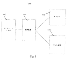
図1は、本発明の一実施形態に係るヘアドライヤーの略ブロック図である。電気加熱式のヘアドライヤー100は、マルチモードトリガ102、制御装置104,ヒーター106とファン装置108を有する。制御装置104は、通常1以上のIC部品により構成される。ヒーター106は、熱を発生する。ヒーター106は、どのような電熱線であってもよく、電気エネルギーを熱に変換することができる。ファン装置108は、送風を発生する。ファン装置108は、送風を発生させるためのファンと電気モータを有する。ヒーター106とファン装置108はそれぞれ制御装置104に接続されている。制御装置104は、ファン装置108に対してはパワーレベルの、ヒーター106に対しては加熱レベルの制御を多くのレベルで、又はそれぞれのレベルを組み合わせて行う。制御装置104はさらにマルチモードトリガ102と接続されている。ユーザは、一つマルチモードトリガ102を介して電気加熱式のヘアドライヤー100を十分に制御することができる。
FIG. 1 is a schematic block diagram of a hair dryer according to an embodiment of the present invention. The electrically heated hair dryer 100 includes a multi-mode trigger 102, a control device 104, a heater 106, and a
さらに、図1を参照すると、電気加熱式のヘアドライヤー100がマルチモードトリガ102で操作されるとき、マルチモードトリガ102は制御装置104を駆動するための信号を発生し、同時に適切な制御をヒーター106とファン装置108に行う。例えば、一旦、制御装置104がマルチモードトリガ102から信号を受信すると、制御装置104に備えられたビルトインされたプログラムに基づいて、ヒーター106とファン装置108を信号に応じた調整方法により制御する。
Still referring to FIG. 1, when the electrically heated hair dryer 100 is operated with a multi-mode trigger 102, the multi-mode trigger 102 generates a signal to drive the controller 104, while simultaneously applying the appropriate control to the heater. 106 and the
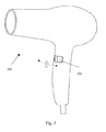
図2は、本発明の一実施形態に係る電気加熱式のヘアドライヤー200の略図である。電気加熱式のヘアドライヤー200は、制御装置104、ヒーター106と、ファン装置108を有する。電気加熱式のヘアドライヤー200は、さらにハンドル201の内側表面に設置されたマルチモードトリガ202を有する。マルチモードトリガ202は、時計回り及び反時計回りに360度回転できる回転ダイヤルを含む。回転ダイヤルには、さらにポテンショメータが備えられており、ポテンショメータは、回転ダイヤルを第1の角度から第2の角度へ回すことにより信号を発生する。加熱レベルや送風のパワーの制御及び調整は、マルチモードトリガ102からの信号に応じて制御装置104のビルトインプログラムにより行われる。
FIG. 2 is a schematic diagram of an electrically
電気加熱式のヘアドライヤー200では、主な動作を制御する制御装置104は、マルチモードトリガ102からの信号を読み、ヒーター及びファンを制御するための応答を提供するよう設定された、IC部品にあるビルトインプログラムを有している。例えば、ヒーター104により生じる熱がレベルA、ファン装置108から生じる送風がレベルBに調整されるように、制御装置104が受信した信号によって、電気加熱式のヘアドライヤー200の制御装置104は、ヒーター104及びファン装置108を制御する。
In the electrically
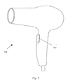
図3は、本発明の別のの実施形態に係る電気加熱式のヘアドライヤー300の略図である。電動ドライヤー300は、一回転より限られた角度の範囲、本例では270度以内で回転可能なマルチモードトリガ302であることを除けば、実質的に図2の電動ドライヤー200と同じデザインである。そのような構造により、ある極端な位置にダイヤルされる場合にオン/オフする、ON/OFFスイッチとしてマルチモードトリガ302を使うことができる。
FIG. 3 is a schematic diagram of an electrically
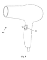
図4及び5は、本発明の他の実施形態に係るマルチモードトリガを有する二つの電気加熱式のヘアドライヤー400,500を示している。図4では、マルチモードトリガは、上下方向に切り替え可能であるトグルスイッチ402であるのに対し、図5では、左右方向に切り替え可能であるトグルスイッチ502である。
4 and 5 show two electrically
図6は、本発明の更なる実施形態に係るマルチモードトリガを有する電気加熱式のヘアドライヤー600を示している。マルチモードトリガ602は少なくとも上下左右(すなわち、4方向)に切り替えることができる多方向性トグルロッドを有する。多方向性トグルロッドはシングルロッドであり、ハンドルから突き出ている。デフォルトでは、シングルロッドはハンドルに対して直立する方向になるよう向けられている。(すなわち、どの方向にも傾いていない。)一つのロッドが押される又は切り替えられると、ポテンショメータに接続され、対応する信号を発生し、関連する制御のために信号が制御装置104に送られる。
FIG. 6 shows an electrically
図7は、本発明の更なる実施形態に係る電気加熱式のヘアドライヤー700を示している。電気加熱式のヘアドライヤー700は、上下方向のパッド702を有する。この上下方向のパッド702は、より操作がユーザーフレンドリーとなるようにソフトタッチのボタンまたはそれに類するものであってもよい。上下方向のパッドは上述したトグルと似た動作が設定されていてもよい。
FIG. 7 shows an electrically
図8は、本発明の更に別の実施形態に係るマルチモードトリガ802を示している。マルチモードトリガ802は、プッシュボタンである。
FIG. 8 illustrates a
更なる実施形態において、マルチモードトリガは、一以上の前述したトリガを統合した一つのトリガであってもよい。 In further embodiments, the multi-mode trigger may be a single trigger that combines one or more of the previously described triggers.
前述した実施形態におけるトリガは、中間レベルを与えることもあれば、与えない場合もある。中間レベルを与えるトリガは、より細かな電気加熱式のヘアドライヤーの動作制御を行うことができる。 The trigger in the above-described embodiment may or may not give an intermediate level. A trigger that provides an intermediate level can provide finer control of the operation of an electrically heated hair dryer.
他の実施形態において、マルチモードトリガは、無段階マルチモードトリガ、つまり、連続的な信号の量である。制御装置104は作動中の信号量を取得するためにサンプリングレートを有していても良い。 In other embodiments, the multi-mode trigger is a stepless multi-mode trigger, ie, a continuous signal quantity. The controller 104 may have a sampling rate to obtain the amount of signal during operation.
更なる実施形態において、制御装置104は予め決められたステップで熱と送風のレベルを制御する。すなわち、それぞれのステップは規定された熱/送風レベルに対応している。更なる別の実施形態において、制御装置104は、熱又は送風又はこれらの組みあわせに関し、事前に決められたレベルである複数の動作モードを有する。 In a further embodiment, the controller 104 controls the heat and blow levels in predetermined steps. That is, each step corresponds to a defined heat / fan level. In yet another embodiment, the controller 104 has a plurality of operating modes that are at predetermined levels for heat or air blowing or a combination thereof.
更なる実施形態において、マルチモードトリガは、電気加熱式のヘアドライヤーのハンドル上に設けられる。また、マルチモードトリガは、送風シリンダーの上や、別個のリモートコントロール装置上といった、電気加熱式のヘアドライヤーの他の位置に設けられていても良い。 In a further embodiment, the multi-mode trigger is provided on the handle of an electrically heated hair dryer. In addition, the multi-mode trigger may be provided at other positions of the electrically heated hair dryer, such as on the blower cylinder or on a separate remote control device.
更なる他の実施形態において、マルチモードトリガは上述した各々の具体例におけるスイッチ機能を統合していてもよい。例えば、電源のオンオフを回転部を所定の方向に回すまたはそれに類似した方法で行うことがあげられる。 In still other embodiments, the multi-mode trigger may integrate the switch function in each of the specific examples described above. For example, the power can be turned on or off by rotating the rotating unit in a predetermined direction or by a method similar to that.
本発明の他の実施例によれば、電気加熱式のヘアドライヤーは、ヒーターと、電動部と、マルチモードトリガと、ヒーターと、電動部及びマルチモードトリガに接続され、マルチモードトリガからの信号に応じてヒーターとマルチモードトリガを同時制御するために用いられる集積回路とを有し、電気加熱式のヘアドライヤーの作動温度及び送風がシンプルな動作で制御される。なぜなら、電気加熱式のヘアドライヤーのパワーは、ビルトインされたプログラムで制御され、調整されるからである。このように構成することにより消費エネルギーを節約し、ユーザの満足度を向上させることができる。加えて、ユーザの様々な操作ニーズに応じて多様なマルチモードトリガが提供されうる。 According to another embodiment of the present invention, an electric heating hair dryer is connected to a heater, an electric part, a multi-mode trigger, a heater, an electric part and a multi-mode trigger, and a signal from the multi-mode trigger. Accordingly, the heater and the integrated circuit used to control the multi-mode trigger at the same time are controlled, and the operating temperature and the air flow of the electric heating hair dryer are controlled by a simple operation. This is because the power of an electrically heated hair dryer is controlled and adjusted by a built-in program. With this configuration, energy consumption can be saved, and user satisfaction can be improved. In addition, various multi-mode triggers can be provided according to various operation needs of the user.
図9は、本発明の更なる実施形態に係る電気加熱式のヘアドライヤー900である。電気加熱式のヘアドライヤー900は、さらに動作情報を表示するための液晶ディスプレー905を有する。例えば、液晶ディスプレーは、現在の熱レベルと送風レベル、あるいは現在の動作モードを表示してもよい。
FIG. 9 is an electrically
図10は、本発明の他の実施形態に係る電気加熱式のヘアドライヤー950の断面図である。制御装置104のIC部品がプリント基板(PCB)上に実装される。また、PCBがさらに電圧変換器を有する場合には、電気加熱式のヘアドライヤー950が電圧の異なる多様な地域で使えるようにIC部品を構成することもできる。さらに、PCBは、スイッチング電源を供給しうる。公知のヘアドライヤーに示唆されていないPCBを採用することで、ヘアドライヤー950は、公知のヘアドライヤーよりも多くの機能や制御を実現することができる。例えば、PCBは、誤作動があった場合の自動電源オフ機能といった安全面の機能を含めることが可能である。
FIG. 10 is a cross-sectional view of an electrically
PCBは、ハンドルの空洞部分に実装される。PCBは、ハンドルの中に設置される。電気加熱式のヘアドライヤー950のヒーター部分から最も遠い位置だからである。
The PCB is mounted in the cavity portion of the handle. The PCB is installed in the handle. This is because it is the farthest position from the heater portion of the electrically
図11は、本発明の更なる実施形態に係る電気加熱式のヘアドライヤー980の吹き出し口の断面図である。電気加熱式のヘアドライヤー980は、さらに、遠赤外線エミッタ985が、ヘアドライヤーの吹き出し口に実装される。遠赤外線エミッタ985は、血液の循環をよくするために使用される。
FIG. 11 is a cross-sectional view of the outlet of an electrically
以上が、本発明の実施例の詳細である。なお、本発明は上記実施例に限定されるものではなく、本発明の趣旨に基づいて種々の変形・改良が可能であり、これらは本発明の範疇である。 The above is the details of the embodiment of the present invention. In addition, this invention is not limited to the said Example, Based on the meaning of this invention, various deformation | transformation and improvement are possible, These are the category of this invention.
一つの実施態様においては、マルチモードスイッチは回転ダイヤルである。また、マルチモードスイッチはトグルスイッチで構成し得る。トグルスイッチは上下方向又は左右方向に切り替え可能でもよい。また、トグルスイッチは、少なくとも上下左右に切り替えることができる多方向性トグルスイッチでもよい。 In one embodiment, the multimode switch is a rotary dial. In addition, the multimode switch may be configured with a toggle switch. The toggle switch may be switchable up and down or left and right . The toggle switch may be a multidirectional toggle switch that can be switched at least up, down, left and right.
電気加熱式のヘアドライヤー200では、主な動作を制御する制御装置104は、マルチモードトリガ102からの信号を読み、ヒーター及びファンを制御するための応答を提供するよう設定された、IC部品にあるビルトインプログラムを有している。例えば、ヒーター106により生じる熱がレベルA、ファン装置108から生じる送風がレベルBに調整されるように、制御装置104が受信した信号によって、電気加熱式のヘアドライヤー200の制御装置104は、ヒーター106及びファン装置108を制御する。
In the electrically
図7は、本発明の更なる実施形態に係る電気加熱式のヘアドライヤー700を示している。電気加熱式のヘアドライヤー700は、上下方向のパッド702を有する。この上下方向のパッド702は、より操作がユーザーフレンドリーとなるようにソフトタッチのボタンまたはそれに類するものであってもよい。上下方向のパッドは上述したトグルスイッチやトグルロッドと似た動作が設定されていてもよい。
FIG. 7 shows an electrically
Claims (14)
プログラム可能な集積回路(IC)が実装され、前記ファンと前記ヒーターが接続されたPCBボードと、
それぞれ単独で、又は任意の組み合わせで前記ファンと前記ヒーターの作動レベルを規定する複数のプリセットスイッチと、
前記PCBボードに接続され、複数のプリセットスイッチを制御するマルチモードスイッチと、を有し、
前記マルチモードスイッチは、前記ヘアドライヤーにおいて片手で操作できる位置に置かれ、ユーザは、ヘアドライヤーを握っている手のみで、前記マルチモードスイッチを介して前記複数のプリセットスイッチを制御し、ヘアドライヤーを操作することができるヘアドライヤー。 A hair dryer having a fan and a heater,
A PCB board mounted with a programmable integrated circuit (IC) and connected to the fan and the heater;
A plurality of preset switches each defining an operating level of the fan and the heater alone or in any combination;
A multi-mode switch connected to the PCB board for controlling a plurality of preset switches,
The multi-mode switch is placed at a position where the hair dryer can be operated with one hand, and the user controls the plurality of preset switches via the multi-mode switch with only a hand holding the hair dryer, Can operate a hair dryer.
請求項1記載のヘアドライヤー。 The multi-mode switch is a rotary dial;
The hair dryer according to claim 1.
請求項1記載のヘアドライヤー。 The multi-mode switch is a toggle switch,
The hair dryer according to claim 1.
請求項3記載のヘアドライヤー。 The toggle switch can be switched vertically.
The hair dryer according to claim 3.
請求項3記載のヘアドライヤー。 The toggle switch can be switched vertically.
The hair dryer according to claim 3.
請求項3記載のヘアドライヤー。 The toggle switch is a multidirectional toggle switch that can be switched at least up, down, left and right,
The hair dryer according to claim 3.
請求項1記載のヘアドライヤー。 The multi-mode switch is a push button;
The hair dryer according to claim 1.
請求項1記載のヘアドライヤー。 The button is a button having a first button and a second button, or the button part is a single button,
The hair dryer according to claim 1.
請求項1〜8のいずれか1項に記載のヘアドライヤー。 The multimode switch is any combination of the multimode switches according to claims 1 to 8.
The hair dryer according to any one of claims 1 to 8.
請求項1〜7のいずれか1項に記載のヘアドライヤー。 The multi-mode switch is arranged on the upper part of the handle of the hair dryer,
The hair dryer according to any one of claims 1 to 7.
請求項1記載のヘアドライヤー。 The hair dryer further has a far infrared emitter connected to the PCB board, and the operating state of the far infrared emitter is determined by one of the preset switches.
The hair dryer according to claim 1.
請求項1記載のヘアドライヤー。 The hair dryer further includes an ion generator connected to the PCB board, and an operation state of the ion generator is determined by one of the preset switches.
The hair dryer according to claim 1.
請求項1記載のヘアドライヤー。 The PCB further includes a switching power supply unit.
The hair dryer according to claim 1.
請求項1記載のヘアドライヤー。
The PCB includes an automatic cutting circuit,
The hair dryer according to claim 1.
Applications Claiming Priority (4)
| Application Number | Priority Date | Filing Date | Title |
|---|---|---|---|
| CN200820235752.6 | 2008-12-29 | ||
| CNU2008202357526U CN201341552Y (en) | 2008-12-29 | 2008-12-29 | Electric hair dryer |
| WOPCT/SG2009/000335 | 2009-09-14 | ||
| PCT/SG2009/000335 WO2010077207A1 (en) | 2008-12-29 | 2009-09-14 | Hair dryer |
Publications (2)
| Publication Number | Publication Date |
|---|---|
| JP2010155061A JP2010155061A (en) | 2010-07-15 |
| JP2010155061A6 true JP2010155061A6 (en) | 2011-01-06 |
Family
ID=41273135
Family Applications (1)
| Application Number | Title | Priority Date | Filing Date |
|---|---|---|---|
| JP2009220794A Pending JP2010155061A (en) | 2008-12-29 | 2009-09-25 | Hair dryer |
Country Status (19)
| Country | Link |
|---|---|
| US (1) | US20100162585A1 (en) |
| EP (1) | EP2201858B1 (en) |
| JP (1) | JP2010155061A (en) |
| KR (1) | KR101177022B1 (en) |
| CN (1) | CN201341552Y (en) |
| AR (1) | AR074945A1 (en) |
| AU (1) | AU2009230727B2 (en) |
| CA (1) | CA2748536C (en) |
| CL (1) | CL2011001609A1 (en) |
| DK (1) | DK2201858T3 (en) |
| HK (1) | HK1143291A1 (en) |
| IL (1) | IL213816A0 (en) |
| MX (1) | MX2011007008A (en) |
| MY (1) | MY153761A (en) |
| PE (1) | PE20100625A1 (en) |
| RU (1) | RU2523247C2 (en) |
| SG (1) | SG172410A1 (en) |
| UY (1) | UY32373A (en) |
| WO (1) | WO2010077207A1 (en) |
Families Citing this family (19)
| Publication number | Priority date | Publication date | Assignee | Title |
|---|---|---|---|---|
| KR200364346Y1 (en) * | 2004-06-29 | 2004-10-11 | 주식회사 텐틴 | hair dryer |
| US20120266483A1 (en) * | 2011-04-20 | 2012-10-25 | Goody Products, Inc. | Blow Dryer and Controls for Same |
| GB2515810B (en) | 2013-07-05 | 2015-11-11 | Dyson Technology Ltd | A hand held appliance |
| GB2515815B (en) * | 2013-07-05 | 2015-12-02 | Dyson Technology Ltd | A hand held appliance |
| CN103549751A (en) * | 2013-11-12 | 2014-02-05 | 孙生强 | Hair dryer and system thereof |
| JP2016135229A (en) * | 2015-01-23 | 2016-07-28 | 日本電産株式会社 | Hair dryer |
| GB2558415B (en) * | 2015-05-22 | 2019-02-06 | Dyson Technology Ltd | A hand held appliance |
| GB2543537B (en) | 2015-10-21 | 2018-09-19 | Dyson Technology Ltd | A handheld appliance |
| GB2543536B (en) * | 2015-10-21 | 2019-01-02 | Dyson Technology Ltd | A handheld appliance |
| GB2543538B (en) | 2015-10-21 | 2018-05-09 | Dyson Technology Ltd | A haircare appliance |
| CN107453541A (en) * | 2016-06-01 | 2017-12-08 | 德昌电机(深圳)有限公司 | Motor and the fan with the motor |
| US20180042352A1 (en) * | 2016-08-10 | 2018-02-15 | Spectrum Brands, Inc. | Hair styling apparatus having dual switch and lock actuator |
| CN106264285A (en) * | 2016-09-22 | 2017-01-04 | 中国地质大学(武汉) | A kind of hand dryer utilizing hair-dryer kinetic energy to convert |
| KR101983636B1 (en) * | 2016-10-21 | 2019-05-29 | 주식회사 동서에이치앤비 | Apparatus of Hairdryer for low noise with clean air |
| KR102014436B1 (en) * | 2018-04-30 | 2019-08-26 | 전남대학교 산학협력단 | Hair Dryer Having Detailed Control for Wind-Strength and Temperature |
| CN109619796B (en) * | 2018-11-07 | 2021-09-14 | 深圳素士科技股份有限公司 | Switch control method, device, electronic equipment and computer readable storage medium |
| GB2580416B (en) * | 2019-01-11 | 2022-09-07 | Dyson Technology Ltd | A haircare appliance |
| CN110037422A (en) * | 2019-05-22 | 2019-07-23 | 莱克电气股份有限公司 | Potentiometer linkage adjustment mechanism and hair dryer |
| KR102273298B1 (en) * | 2019-09-18 | 2021-07-07 | 주식회사 터보이온코리아 | Easy to use hair dryer |
Family Cites Families (21)
| Publication number | Priority date | Publication date | Assignee | Title |
|---|---|---|---|---|
| JPS55501128A (en) * | 1978-10-20 | 1980-12-18 | ||
| JPH0263703U (en) * | 1988-10-31 | 1990-05-14 | ||
| JPH04338406A (en) * | 1991-05-14 | 1992-11-25 | Seiko Epson Corp | Dryer |
| JPH07194429A (en) * | 1993-12-29 | 1995-08-01 | Isamu Akasaka | Dryer |
| US5434946A (en) * | 1994-02-03 | 1995-07-18 | Helen Of Troy Corporation | Hair dryer with continuously variable heat intensity and air flow speed |
| JP3315245B2 (en) * | 1994-05-12 | 2002-08-19 | アルプス電気株式会社 | Multi-directional input switch |
| EP0792113B1 (en) * | 1995-09-13 | 2001-12-05 | Koninklijke Philips Electronics N.V. | Hair-care appliance with hair-moistness measurement by measuring the resistance of the hair |
| US5841943A (en) * | 1997-04-25 | 1998-11-24 | Soundesign, Llc | Ducted flow hair dryer with multiple impellers |
| KR19990043498A (en) * | 1997-11-29 | 1999-06-15 | 윤종용 | Hair dryer |
| US20030034874A1 (en) * | 1998-10-29 | 2003-02-20 | W. Stephen G. Mann | System or architecture for secure mail transport and verifiable delivery, or apparatus for mail security |
| JP2004063317A (en) * | 2002-07-30 | 2004-02-26 | Japan Aviation Electronics Industry Ltd | Rocking type multidirectional switch |
| FR2848075B1 (en) * | 2002-12-05 | 2006-04-28 | Seb Dev | HAIR DRYER |
| GB0310700D0 (en) * | 2003-05-09 | 2003-06-11 | Freedom Innovations Ltd | Hairdryer |
| JP2005177234A (en) * | 2003-12-22 | 2005-07-07 | Matsushita Electric Works Ltd | Hair dryer |
| KR200364346Y1 (en) * | 2004-06-29 | 2004-10-11 | 주식회사 텐틴 | hair dryer |
| KR100562714B1 (en) * | 2004-07-31 | 2006-03-23 | (주)성신이엔씨 | Hair dryer |
| JP2006150060A (en) * | 2004-11-30 | 2006-06-15 | Kica Inc | Drier |
| US7145087B1 (en) * | 2005-08-29 | 2006-12-05 | Zippy Technology Corp. | Multi-instruction switch |
| KR20070048354A (en) * | 2005-11-04 | 2007-05-09 | 두나 엔터프라이지즈 에스.에이. | Programmable manual hair dryer with multiple functions |
| WO2007089770A2 (en) * | 2006-01-31 | 2007-08-09 | Polychromix Corporation | Hand-held ir spectrometer with a fixed grating and a diffractive mems-array |
| US7926198B2 (en) * | 2008-05-29 | 2011-04-19 | Pet Projects | Thermoelectric handheld dryer |
-
2008
- 2008-12-29 CN CNU2008202357526U patent/CN201341552Y/en not_active Expired - Fee Related
-
2009
- 2009-09-14 SG SG2011047248A patent/SG172410A1/en unknown
- 2009-09-14 CA CA2748536A patent/CA2748536C/en not_active Expired - Fee Related
- 2009-09-14 MY MYPI2011003045A patent/MY153761A/en unknown
- 2009-09-14 MX MX2011007008A patent/MX2011007008A/en active IP Right Grant
- 2009-09-14 RU RU2011131783/12A patent/RU2523247C2/en not_active IP Right Cessation
- 2009-09-14 WO PCT/SG2009/000335 patent/WO2010077207A1/en active Application Filing
- 2009-09-25 JP JP2009220794A patent/JP2010155061A/en active Pending
- 2009-10-20 US US12/581,903 patent/US20100162585A1/en not_active Abandoned
- 2009-10-21 DK DK09013272.1T patent/DK2201858T3/en active
- 2009-10-21 EP EP09013272.1A patent/EP2201858B1/en not_active Not-in-force
- 2009-10-21 AU AU2009230727A patent/AU2009230727B2/en not_active Ceased
- 2009-10-23 KR KR1020090101407A patent/KR101177022B1/en not_active IP Right Cessation
- 2009-12-29 AR ARP090105165A patent/AR074945A1/en unknown
- 2009-12-29 UY UY0001032373A patent/UY32373A/en not_active Application Discontinuation
- 2009-12-29 PE PE2009001332A patent/PE20100625A1/en not_active Application Discontinuation
-
2010
- 2010-10-21 HK HK10109983.8A patent/HK1143291A1/en not_active IP Right Cessation
-
2011
- 2011-06-28 IL IL213816A patent/IL213816A0/en unknown
- 2011-06-29 CL CL2011001609A patent/CL2011001609A1/en unknown
Similar Documents
| Publication | Publication Date | Title |
|---|---|---|
| JP2010155061A6 (en) | Hair dryer | |
| JP2010155061A (en) | Hair dryer | |
| CN105874210B (en) | The electric fan for having cold wind function | |
| KR100400388B1 (en) | Hair dryer | |
| JP6235421B2 (en) | Fan | |
| KR20060023939A (en) | A motor fan combind using a electric mosquito stick | |
| US20070169369A1 (en) | Hair Drier with 3-Dimensional Control Surface | |
| RU2362469C2 (en) | Hair drier and device for making hairstyle or for hairdressing (versions) | |
| JP5965660B2 (en) | Fan | |
| CN206964297U (en) | Multipole variable speed blower | |
| US20040262284A1 (en) | Cooking device with high-speed heating unit | |
| TWI507149B (en) | Hair dryer | |
| JPH0646921A (en) | Drier | |
| KR200391308Y1 (en) | Hair Dryer | |
| JPH0646920A (en) | Drier | |
| KR200368568Y1 (en) | A Motor Fan Combind Using a Electric Mosquito Stick | |
| JP3856450B2 (en) | Cooker | |
| KR20000005975U (en) | fan | |
| JPH0710641Y2 (en) | Hair dryer | |
| JPH0842924A (en) | Method and apparatus for heat storage warm air heating | |
| JPH0747042Y2 (en) | Hair dryer | |
| JPH01310257A (en) | Warm-air space heater | |
| JP2003293982A (en) | Home electric appliance | |
| JPH03136623A (en) | Control method for hot air temperature in hot air drying device | |
| JPH09303790A (en) | Heat-cooker |