EP0792113B1 - Hair-care appliance with hair-moistness measurement by measuring the resistance of the hair - Google Patents
Hair-care appliance with hair-moistness measurement by measuring the resistance of the hair Download PDFInfo
- Publication number
- EP0792113B1 EP0792113B1 EP96927161A EP96927161A EP0792113B1 EP 0792113 B1 EP0792113 B1 EP 0792113B1 EP 96927161 A EP96927161 A EP 96927161A EP 96927161 A EP96927161 A EP 96927161A EP 0792113 B1 EP0792113 B1 EP 0792113B1
- Authority
- EP
- European Patent Office
- Prior art keywords
- hair
- output
- care appliance
- resistor
- resistance
- Prior art date
- Legal status (The legal status is an assumption and is not a legal conclusion. Google has not performed a legal analysis and makes no representation as to the accuracy of the status listed.)
- Expired - Lifetime
Links
Images


Classifications
-
- A—HUMAN NECESSITIES
- A45—HAND OR TRAVELLING ARTICLES
- A45D—HAIRDRESSING OR SHAVING EQUIPMENT; EQUIPMENT FOR COSMETICS OR COSMETIC TREATMENTS, e.g. FOR MANICURING OR PEDICURING
- A45D20/00—Hair drying devices; Accessories therefor
- A45D20/04—Hot-air producers
- A45D20/08—Hot-air producers heated electrically
- A45D20/10—Hand-held drying devices, e.g. air douches
- A45D20/12—Details thereof or accessories therefor, e.g. nozzles, stands
- A45D20/122—Diffusers, e.g. for variable air flow
-
- A—HUMAN NECESSITIES
- A45—HAND OR TRAVELLING ARTICLES
- A45D—HAIRDRESSING OR SHAVING EQUIPMENT; EQUIPMENT FOR COSMETICS OR COSMETIC TREATMENTS, e.g. FOR MANICURING OR PEDICURING
- A45D20/00—Hair drying devices; Accessories therefor
Definitions
- the invention relates to a hair-care appliance comprising:
- a hair-care appliance is known from United States Patent US 4,877,042.
- a hair-care appliance is to be understood to mean an electrically heated device, which may or may not incorporate a blower, for curling, shaping or styling the hair.
- Such appliances include a hair brush, a hair curler and hair comb without blower, and a hair dryer and hot air brush with blower. Grooming the hair is often effected by first moistening the hair and then shaping it into the desired style with the styling means of the hair-care appliance, in combination or not in combination with a comb or curlers. The hair is dried by the heat of the heating element, for which care must be taken that the hair cannot become too dry because dry hair is more liable to be damaged.
- the known hair-care appliance comprises electrodes which contact the hair and a measurement circuit which measures the resistance of the hair.
- the resistance of the hair depends on the moistness of the hair. Dry hair has a comparatively high resistance and wet hair has a comparatively low resistance. The resistance variation is fairly large and therefore it is quite difficult to determine when the resistance passes a certain threshold, so as to allow signalling that the moistness of the hair has reached the desired value.
- Patent Abstracts of Japan, Vol 15, No. 100, C-813 abstract of JP 3-8 A also discloses a hair-care appliance as recited in the opening paragraph.
- the hair-care appliance of the type defined in the opening paragraph is characterized in that the measurement circuit comprises:
- the first resistor, the second resistor and the resistance of the hair between the electrodes form a T network energized by the voltage source.
- the signal current through the second resistor flows into the converter, which converts it into a suitable measurement signal.
- the signal current through the second resistor is a fraction of the current through the first resistor, because part of it is shunted by the hair resistance between the electrodes.
- the advantage of this configuration is that the dynamic range of the signal current is reduced. A comparatively large variation in the hair resistance produces a comparatively smaller signal current variation. As a result, measurement is possible over a larger resistance range with the same resolution.
- the T network reduces the impedance level of the measurement circuit, which renders the measurement circuit more immune to spurious signals, particularly as a result of capacitive coupling to the electric mains.
- Enzyklopädie der Elektrotechnik, Script of Technical University Graz, 1989, pages 248, 249, 265 and 266 discloses a three-resistor T-network circuit energized by a voltage source for measuring the resistance of an unknown resistor.
- the integrator and the comparator together with the T network form a resistance-to-frequency converter, the output of the comparator also serving as the alternating voltage source for the T network.
- the inverting input of the differential amplifier of the integrator receives the signal current via the second resistance. In the case of moist hair the resistance between the electrodes is low and the signal current is small. It then takes a comparatively long time before the output signal of the integrator reaches the reference voltage and the voltage on the comparator output changes over. After the change-over the direction of the signal current is reversed and the output voltage of the integrator will increase in the opposite direction until the reference voltage is reached again.
- the third and the fourth resistor produce hysteresis in the comparator, as a result of which the output voltage of the integrator has to assume two different levels in order to cause the comparator to change over. Owing to the comparatively small signal current to the integrator in the case of moist hair, the frequency at which the comparator output changes over is relatively low. In the case of dry hair the hair resistance is high and the signal current is large. The change-over frequency is then comparatively high.
- the measurement signal supplied by the converter can be employed to warn the user that the hair becomes too dry by means of a sound signal.
- the hair-care appliance further comprises means for comparing the measurement signal with a reference signal, and means for turning off the heating element in response to the comparison. As soon as the desired moistness is reached the heating is turned off so as to preclude overheating.
- the heating is turned off so as to preclude overheating.
- hair-care appliances having a blower it is then also possible to switch off the blower.
- a further embodiment of the hair-care appliance is characterized in that the hair-care appliance comprises a timer for supplying an activation signal to a signalling device after the heating element has been turned off. If desired, the activation signal can then also turn off the blower.
- an embodiment of the hair-care appliance is characterized in that the means for comparing comprise: a first monostable multivibrator having an output and having a trigger input coupled to the output of the comparator; a second monostable multivibrator having an output and having a trigger input coupled to the output of the first monostable multivibrator; and the means for turning off the heating element comprise: an electronic switch having a main current path in series with the heating element and having a control input coupled to the output of the second monostable multivibrator.
- the first monostable multivibrator In the case of a high frequency the first monostable multivibrator is triggered so frequently that the output remains at a given direct voltage. The second monostable multivibrator is then not triggered. From a given low frequency the output temporarily assumes another value and the second monostable multivibrator is then triggered. The output signal of the second multivibrator indicates whether the frequency is above or below a given value and this signal controls an electronic switch which turns on and turns off the heating element.
- the circuit for measuring the hair resistance can also be used for measuring other resistance values, for example those of NTC and PTC resistors in thermostats, light-sensitive resistors in lighting switches, i.e. for uses where a resistance variation is to be monitored.
- FIG. 1 shows a hair-care appliance, particularly a hair dryer.
- the hair dryer has a housing 2 with a handle 4 provided with a control switch 6.
- the housing accommodates (not shown) a heating element, a blower and actuation, measurement and control electronics with an associated power supply.
- the air drawn in by the blower and, if applicable, heated by the heating element emerges from the housing via an outlet 8, onto which a diffuser 10 can be fitted to spread the air.
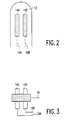
- the diffuser 10 has diffuser tips 12, which come into contact with the hair to be dried during use of the hair dryer.
- one or more of the diffuser tips 12 carry electrodes 14A/14B, which by means of connection wires 16A/16b, concealed in the diffuser tips 12 and the diffuser 10, are connected to corresponding connection wires in the housing 8.
- the electrodes 14A/14B can be made of any suitable material, for example copper foil.
- the electrodes 14A/14B are in contact with a hair 18, as is shown in Figure 3.
- electrodes may be arranged at suitable locations on the outlet 8 to allow the hair dryer to be used without a diffuser.
- the hair-care appliance may be a hot air brush, where hot air emerges from a brush.
- the electrodes are arranged at suitable points of the brush structure.
- the electrodes are arranged at locations where the hair to be groomed comes into contact with the appliance.
- the moistness of the hair is determined by measuring the resistance of the hairs which are in contact with the electrodes 14A/14B. Wet hair has a comparatively low resistance and dry hair has a comparatively high resistance.
- Figure 4 shows the basic diagram of the resistance measuring device.
- the hair resistance R x to be measured between the electrodes 14A and 14B is included in a T network, which further comprises a first resistor 20 connected between a first terminal 22 and the electrode 14A, and a second resistor 24 connected between the electrode 14A and a second terminal 26.
- a voltage source 28 is connected to the first terminal 22 and the electrode 14B and a converter 30 is connected to the second terminal 26 and the electrode 14B.
- the voltage source 28 supplies a current to the T network, a part of which current, i.e.
- the signal current I s to be measured flows through a current path which extends from the second terminal 26 to the electrode 14B via the converter 30.
- the voltage source 28 is preferably a source with an a.c. component, which component is used for the measurement of the hair resistance.
- a coupling capacitor can be arranged in series with one of the electrodes 14A/14B to block the d.c. component.
- the converter 30 converts the signal current I s into a measurement signal MS which is a measure of the resistance R x of the hair.
- the operation of the converter 30 can be based on a measurement of the voltage across a resistance in series with the second resistor 24 and a comparison of the measured voltage with a reference voltage which has been determined by experiment and which corresponds to a given degree of moistness of the hair.
- a measurement based on the current I s is to be preferred because of the lower impedance level at the second terminal 26.
- the T network configuration reduces the impedance level between the voltage source 28 and the second terminal 26, as a result of which spurious signals, particularly those resulting from capacitive coupling between the mains voltage and the second terminal 26, have less effect.
- a suitable choice of the resistance value R 1 for the first resistor 20 and of the resistance value R 2 for the second resistor 24 reduces the dynamic range of the signal current I s .
- the resistance value R x should vary to a comparatively greater extent for a given variation in the signal current I s than in the case that the resistance R x to be measured had been arranged directly between the voltage source 28 and the second terminal 26.
- FIG. 5 shows a more detailed diagram of the converter 30.
- the values given for the resistors and capacitors and the type numbers of the electronic devices are merely given by way of illustration and example.
- the converter is a resistance-to-frequency converter comprising an integrator 32 formed by a differential amplifier 34 of the type TLC 252, having an inverting input 36 coupled to the second terminal 26 of the T network, and a 10 nF capacitor 38 connected between an output 40 of the differential amplifier 34 and the inverting input 36.
- the converter 30 further comprises a comparator 42, also of the type TLC 252, having an output 44 connected to the first terminal 22 of the T network, and a non-inverting input 46, which is coupled to the output 40 of the differential amplifier 34 via a 33 k ⁇ resistor 48 and to the output 44 of the comparator 42 via a 47 k ⁇ resistor 50, which output supplies the measurement signal MS.
- the other inputs of the differential amplifier 34 and the comparator 42 are connected to a reference voltage terminal 56, connected for example to half the supply voltage of the differential amplifier 34 and the comparator 42.
- the electrode 14A is connected to the resistors 20 and 24 of the T network, which resistors both have a value of 470 k ⁇ , via a 1 ⁇ F coupling capacitor 52 and a 10 k ⁇ resistor 54.
- the electrode 14B is connected to the reference voltage terminal 56.
- a 470 pF interference suppression capacitor 58 is arranged across the electrodes 14A and 14B.
- the integrator 32 and the comparator 42 together with the T network form a resistance-to-frequency converter, the output 44 of the comparator 42 also forming the a.c. source for the T network.
- the signal current I s through the resistor 24 flows into the inverting input 36 of the differential amplifier 34. In the case of moist hair the resistance between the electrodes 14A/14B is low and the signal current I s is small. It then takes a comparatively long time before the output signal of the integrator 32 reaches the reference voltage on the reference voltage terminal 56 and the measurement signal MS on the comparator output 44 changes over. After the change-over the direction of the signal current I s is reversed and the output voltage of the integrator 32 will increase in the opposite direction until the reference voltage is reached again.
- the resistor 48 and the resistor 50 produce hysteresis in the comparator 42, as a result of which the output voltage of the integrator 32 has to assume two different levels in order to cause the comparator 42 to change over.
- the frequency at which the measurement signal MS changes over is relatively low and the measurement signal will have a waveform as shown at MS W in Fig. 6.
- the hair resistance is high and the signal current I s is large.
- the frequency of the measurement signal MS is then comparatively high, as shown at MS D in Fig. 6.
- the variable frequency of the measurement signal MS is compared with a reference frequency which is representative of a hair moistness at which the heating element of the hair-care appliance should be turned off in order to preclude excessive drying and damage to the hair.
- Figure 7 shows a circuit suitable for this purpose. Again, the values given for the resistors and capacitors and the type numbers of the electronic devices are merely given by way of illustration and example.
- the measurement signal MS is applied to the negative trigger input -T of a first monostable multivibrator 60 of the type HEF 4538, which has its positive trigger input +T and its reset input R connected to the positive supply voltage.
- the time constant of the monostable multivibrator 60 is determined by a 680 nF capacitor 62 across the terminals CX and RC of the monostable multivibrator 60 and by a variable 100 k ⁇ resistor 64 and a fixed 39 k ⁇ resistor 66 between the terminal RC and the positive supply voltage.
- the output QN will change over from a relatively positive value to a relatively negative value and this state will be sustained for a time determined by the capacitor 62 and the resistors 64 and 66. After this, the output QN will automatically resume the relatively positive value.
- the output QN of the monostable multivibrator 60 is connected to the negative trigger input -T of a second monostable multivibrator 68, also of the type HEF 4538, which has its positive trigger input +T and its reset input R connected to the positive supply voltage.
- the time constant of the second monostable multivibrator 68 is determined by a 680 nF capacitor 70 across the terminals CX and RC of the monostable multivibrator 68 and by an 820 k ⁇ resistor 72 between the terminal RC and the positive supply voltage.
- the Q output of the second monostable multivibrator 68 drives the base of a switching transistor 76 via a resistor 74, which transistor energizes a relay 80 via an optional LED 78.
- the relay 80 actuates a switch 82 which connects a heating element 84 to the mains voltage, which can be turned on by means of the switch 6 on the handle.
- the first monostable multivibrator 60 is triggered so frequently that the output QN remains constantly relatively low.
- the second monostable multivibrator 68 is then not triggered.
- the output QN of the first monostable multivibrator 60 will temporarily go high and then low again, causing the second monostable multivibrator 68 to be triggered.
- the signal on the output Q of the second monostable multivibrator 68 thus indicates whether the frequency is above or below a given value and this signal controls an electronic switch which turns on and turns off the heating element.
- the output Q of this second monostable is high, the relay is energized by the transistor 76, and the heating element 84 is energized via the switch 82.
- the triggering of the second monostable multivibrator 68 ceases, and the heating element 84 is turned off.
- the blower motor 86 may be connected directly to the mains voltage via a connection 88.
- the blower is then started when the mains voltage is switched on by means of the switch 6.
- the LED 78 in series with the relay 80 indicates that the heating element is on. After the heating element has been turned off the blower continues to rotate. The cool air stream then promotes a better fixation of the hair.
- the output Q of the second monostable multivibrator 68 is further connected to the negative trigger input -T of a third monostable multivibrator 90, which is also of the type HEF 4538, which has its positive trigger input +T and its reset input R connected to the positive supply voltage.
- the time constant of the third monostable multivibrator 90 is determined by a 33 ⁇ F capacitor 92 across the terminals CX and RC and by a 470 k ⁇ variable resistor 94 and a 10 k ⁇ resistor 96 between the terminal RC and the positive supply voltage.
- the output Q of the third monostable multivibrator 90 is, in its turn, connected to the negative trigger input -T of a fourth monostable multivibrator 98, again of the type HEF 4538, which has its positive trigger input +T connected to the positive supply voltage.
- the reset input R is connected to the output QN of the second monostable multivibrator 68.
- the time constant of the fourth monostable multivibrator 98 is determined by a 10 ⁇ F capacitor 100 across the terminals CX and RC and by a 470 k ⁇ variable resistor 102 and a 10 k ⁇ resistor 104 between the terminal RC and the positive supply voltage.
- the output Q of the fourth monostable multivibrator 98 drives the base of a switching transistor 108 via a resistor 106, which transistor energizes a buzzer 110.
- the buzzer 110 is of a type which produces noise as long as it receives direct voltage.
- the third monostable multivibrator 90 which serves as a timer, is triggered.
- the fourth monostable multivibrator 98 is triggered and the buzzer will produce a sound signal during a time determined by the time constant of the fourth monostable multivibrator 98.
- the buzzer 110 gives the user a signal that the run-out time has expired and that further cooling with cold air is no longer necessary.
- an optional circuit may be provided to switch off the blower motor 86 after expiry of the run-out time.
- the output QN of the third monostable multivibrator 90 drives the base of a switching transistor 114 via a resistor 112, which transistor energizes a relay 116 whose switching contact 118 takes the place of the fixed connection 88.
- the converter 30 of Fig. 5 and the circuit of Fig. 7 are energized by means of a transformer 118 and a rectifier 120, which provide the required electrical isolation between the mains voltage and the electrodes 14A/14B.
- the comparison of the frequency of the measurement signal MS with a reference frequency can also be effected in another way then described hereinbefore. It is, for example, possible to use an FM discriminator which converts the variable frequency into a varying direct voltage and a comparator which compares the direct voltage with a reference voltage. Another possibility is a microprocessor which counts the number of falling edges of the measurement signal MS within a fixed time window.
- the measurement circuit shown in Figure 4 and the embodiment shown in Figures 5 and 7 are very suitable for use in hair-care appliances.
- the resistance variation of the hair is fairly large and the T network provides a high measurement accuracy and an improved immunity to spurious signals.
- the circuit for measuring the hair resistance can also be used for other purposes. Examples of this are measurements of various other resistance values, for example those of NTC and PTC resistors in thermostats, light-sensitive resistors in lighting switches, i.e. uses where a resistance variation is to be monitored.
Abstract
Description
Claims (6)
- A hair-care appliance comprising:hair-styling means (10, 12); an electric heating element (84) for heating the hair-styling means (10, 12); electrodes (14A, 14B) which enter into contact with the hair to be groomed during use of the hair-care appliance; and a measurement circuit, electrically connected to the electrodes (14A, 14B) for measuring a resistance value (Rx) between the electrodes (14A, 14B) and for converting the resistance value into a measurement signal (MS), characterized in that the measurement circuit comprises: a voltage source (28) connected between a first terminal (22) and a first electrode (14B) of said electrodes (14A; 14B); a first resistor (20) connected between the first terminal (22) and a second electrode (14A) of said electrodes (14A; 14B); a second resistor (24) connected between the second electrode (14A) and a second terminal (26); and a converter (30) for converting a signal current (Is) through a current path from the second terminal (26) to the first electrode (14B) into the measurement signal (MS), the converter (30) comprising: an integrator (32) with a differential amplifier (34) having an inverting input (36) coupled to the second terminal (26), and with a capacitor (38) connected between an output (40) of the differential amplifier (34) and the inverting input (36); a comparator (42) having an output (44) connected to the first terminal (22), having a non-inverting input (46) coupled to the output (40) of the differential amplifier (34) of the integrator (32) via a third resistor (48) and to the output (44) of the comparator (42) via a fourth resistor (50), and having an inverting input arranged to receive a reference voltage (56).
- A hair-care appliance as claimed in Claim 1, characterized in that the hair-care appliance further comprises means (60, 68) for comparing the measurement signal (MS) with a reference signal, and means (76, 80, 82) for turning off the heating element (84) in response to the comparison.
- A hair-care appliance as claimed in Claim 2, characterized in that the hair-care appliance comprises a timer (90) for supplying an activation signal (Q) to a signalling device (98, 110) after the heating element (84) has been turned off.
- A hair-care appliance as claimed in Claim 3, characterized in that the hair-care appliance further comprises a blower (86) and means (114, 116, 118) for switching off the blower (86) in response to the activation signal (QN) from the timer (90).
- A hair-care appliance as claimed in Claim 1, 2 or 3, characterized in that the voltage source (28) is an alternating voltage source (42, 44) and the signal current is an alternating current.
- A hair-care appliance as claimed in Claim 2, 3, 4 or 5, characterized in that the means for comparing comprise: a first monostable multivibrator (60) having an output (QN) and having a trigger input (-T) coupled to the output (44) of the comparator (42); a second monostable multivibrator (68) having an output (Q) and having a trigger input (-T) coupled to the output (QN) of the first monostable multivibrator (60); and the means for turning off the heating element (84) comprise: an electronic switch (76, 80, 82) having a main current path (82) in series with the heating element (84) and having a control input (74, 76) coupled to the output (Q) of the second monostable multivibrator (68).
Priority Applications (1)
| Application Number | Priority Date | Filing Date | Title |
|---|---|---|---|
| EP96927161A EP0792113B1 (en) | 1995-09-13 | 1996-09-02 | Hair-care appliance with hair-moistness measurement by measuring the resistance of the hair |
Applications Claiming Priority (4)
| Application Number | Priority Date | Filing Date | Title |
|---|---|---|---|
| EP95202484 | 1995-09-13 | ||
| EP95202484 | 1995-09-13 | ||
| PCT/IB1996/000879 WO1997009898A1 (en) | 1995-09-13 | 1996-09-02 | Hair-care appliance with hair-moistness measurement by measuring the resistance of the hair, and circuit for converting the resistance value of a resistor into a measurement signal |
| EP96927161A EP0792113B1 (en) | 1995-09-13 | 1996-09-02 | Hair-care appliance with hair-moistness measurement by measuring the resistance of the hair |
Publications (2)
| Publication Number | Publication Date |
|---|---|
| EP0792113A1 EP0792113A1 (en) | 1997-09-03 |
| EP0792113B1 true EP0792113B1 (en) | 2001-12-05 |
Family
ID=8220631
Family Applications (1)
| Application Number | Title | Priority Date | Filing Date |
|---|---|---|---|
| EP96927161A Expired - Lifetime EP0792113B1 (en) | 1995-09-13 | 1996-09-02 | Hair-care appliance with hair-moistness measurement by measuring the resistance of the hair |
Country Status (10)
| Country | Link |
|---|---|
| US (1) | US5857379A (en) |
| EP (1) | EP0792113B1 (en) |
| JP (1) | JPH10510459A (en) |
| KR (1) | KR970706745A (en) |
| CN (1) | CN1106177C (en) |
| AU (1) | AU701115B2 (en) |
| BR (1) | BR9606637A (en) |
| CA (1) | CA2204985A1 (en) |
| DE (1) | DE69617627T2 (en) |
| WO (1) | WO1997009898A1 (en) |
Cited By (2)
| Publication number | Priority date | Publication date | Assignee | Title |
|---|---|---|---|---|
| US7261000B2 (en) | 2004-04-26 | 2007-08-28 | The Procter & Gamble Company | Methods of assessing characteristics of fibrous substrates and treating fibrous substrates |
| US7928739B2 (en) | 2006-06-30 | 2011-04-19 | The Procter & Gamble Company | Device for measuring moisture in substrate and health of hair |
Families Citing this family (25)
| Publication number | Priority date | Publication date | Assignee | Title |
|---|---|---|---|---|
| JP2001508348A (en) * | 1997-11-21 | 2001-06-26 | コーニンクレッカ フィリップス エレクトロニクス エヌ ヴィ | Method and hair dryer for hair drying using a remote sensor of hair moisture content |
| US20040194541A1 (en) * | 2002-06-10 | 2004-10-07 | The Procter & Gamble Company | High-Q LC circuit moisture sensor |
| US6854322B2 (en) * | 2002-06-10 | 2005-02-15 | The Procter & Gamble Company | Directional coupler sensor |
| US7040037B2 (en) * | 2004-05-21 | 2006-05-09 | Kenford Industrial Company Limited | Hairdryer diffuser |
| US7356943B2 (en) * | 2006-05-17 | 2008-04-15 | Sabeeh Behbehani | Automatic hair dryer |
| CN201341552Y (en) * | 2008-12-29 | 2009-11-11 | 刘亚福 | Electric hair dryer |
| EP2272391B1 (en) * | 2009-07-10 | 2020-04-29 | Braun GmbH | Automated hair care process |
| MX353433B (en) | 2009-10-30 | 2018-01-11 | Deka Products Lp | Apparatus and method for detecting disconnection of an intravascular access device. |
| US9138038B2 (en) * | 2011-05-20 | 2015-09-22 | Spectrum Brands, Inc. | Hair styling apparatus having hair-protection function |
| US9999717B2 (en) | 2011-05-24 | 2018-06-19 | Deka Products Limited Partnership | Systems and methods for detecting vascular access disconnection |
| FR2982947B1 (en) * | 2011-11-18 | 2014-01-10 | Seb Sa | METHOD FOR MEASURING THE EFFICIENCY OF A HAIRDRYER |
| CN102960931B (en) * | 2012-11-19 | 2015-09-02 | 温州市中芝贸易有限公司 | Dry wetting detects heater of hair straightener automatically |
| FR3005556B1 (en) * | 2013-05-17 | 2015-06-19 | Seb Sa | METHOD FOR MEASURING THE EFFICIENCY OF A BRUSHED HAIR DRYER |
| WO2015027190A1 (en) * | 2013-08-23 | 2015-02-26 | Mirakel Technologies, Inc. | Systems, devices and methods for styling hair |
| US10463130B2 (en) * | 2015-11-25 | 2019-11-05 | Koninklijke Philips N.V. | Hair styling device |
| CN107228882A (en) * | 2016-03-23 | 2017-10-03 | 北京科百宏业科技有限公司 | A kind of humidity sensor |
| AU201811153S (en) * | 2017-09-25 | 2018-03-20 | Dyson Technology Ltd | Accessory for hairdryers |
| AU201811154S (en) * | 2017-09-25 | 2018-03-20 | Dyson Technology Ltd | Accessory for hairdryers |
| KR102364691B1 (en) | 2020-04-10 | 2022-02-18 | 엘지전자 주식회사 | Diffuser and hair dryer having the same |
| KR102364689B1 (en) | 2020-04-10 | 2022-02-18 | 엘지전자 주식회사 | Diffuser and hair dryer having the same |
| KR102364692B1 (en) | 2020-04-10 | 2022-02-18 | 엘지전자 주식회사 | Hair dryer |
| KR102364682B1 (en) * | 2020-04-10 | 2022-02-18 | 엘지전자 주식회사 | Diffuser and hair dryer having the same |
| KR102366461B1 (en) | 2020-04-10 | 2022-02-23 | 엘지전자 주식회사 | Diffuser and hair dryer having the same |
| KR102366462B1 (en) | 2020-04-10 | 2022-02-23 | 엘지전자 주식회사 | Diffuser and hair dryer having the same |
| GB2614276A (en) * | 2021-12-23 | 2023-07-05 | Dyson Technology Ltd | Haircare appliance |
Family Cites Families (12)
| Publication number | Priority date | Publication date | Assignee | Title |
|---|---|---|---|---|
| AT134139B (en) * | 1930-12-12 | 1933-07-10 | Eduard Mai | Device for determining the degree of hair moisture during hair wave production. |
| GB642877A (en) * | 1948-10-22 | 1950-09-13 | Eugene Ltd | Improvements relating to apparatus for testing the dryness of hair |
| US2654054A (en) * | 1951-01-13 | 1953-09-29 | Weston Electrical Instr Corp | Moisture testing apparatus |
| DE2122561A1 (en) * | 1971-05-07 | 1972-11-09 | Siemens AG, 1000 Berlin u. 8000 München | Measuring amplifier |
| IT1016098B (en) * | 1973-06-22 | 1977-05-30 | Protim And Gallwey Ltd | HAIR MOISTURE INDICATOR DEVICE |
| US4259633A (en) * | 1978-07-25 | 1981-03-31 | Armstrong Cork Company | Method and apparatus for measuring the moisture content of wood |
| JPS59126943A (en) * | 1983-01-11 | 1984-07-21 | Sharp Corp | Measuring device for moisture content |
| US4877042A (en) * | 1983-09-19 | 1989-10-31 | Downey John H | Dynamic hair grooming appliance |
| JP2883165B2 (en) * | 1990-06-01 | 1999-04-19 | 松下電工株式会社 | Hair moisture content measuring device |
| JPH04193203A (en) * | 1990-11-27 | 1992-07-13 | Matsushita Electric Works Ltd | Hair brush provided with moisture sensor |
| JPH04197306A (en) * | 1990-11-29 | 1992-07-16 | Toshiba Corp | Curl brush |
| JPH04336002A (en) * | 1991-05-10 | 1992-11-24 | Toshiba Corp | Curl brush |
-
1996
- 1996-09-02 JP JP9511782A patent/JPH10510459A/en not_active Ceased
- 1996-09-02 EP EP96927161A patent/EP0792113B1/en not_active Expired - Lifetime
- 1996-09-02 WO PCT/IB1996/000879 patent/WO1997009898A1/en active IP Right Grant
- 1996-09-02 CA CA002204985A patent/CA2204985A1/en not_active Abandoned
- 1996-09-02 AU AU67083/96A patent/AU701115B2/en not_active Ceased
- 1996-09-02 CN CN96191344A patent/CN1106177C/en not_active Expired - Fee Related
- 1996-09-02 KR KR1019970703205A patent/KR970706745A/en active IP Right Grant
- 1996-09-02 DE DE69617627T patent/DE69617627T2/en not_active Expired - Fee Related
- 1996-09-02 BR BR9606637A patent/BR9606637A/en not_active Application Discontinuation
- 1996-09-11 US US08/712,028 patent/US5857379A/en not_active Expired - Fee Related
Cited By (2)
| Publication number | Priority date | Publication date | Assignee | Title |
|---|---|---|---|---|
| US7261000B2 (en) | 2004-04-26 | 2007-08-28 | The Procter & Gamble Company | Methods of assessing characteristics of fibrous substrates and treating fibrous substrates |
| US7928739B2 (en) | 2006-06-30 | 2011-04-19 | The Procter & Gamble Company | Device for measuring moisture in substrate and health of hair |
Also Published As
| Publication number | Publication date |
|---|---|
| EP0792113A1 (en) | 1997-09-03 |
| AU701115B2 (en) | 1999-01-21 |
| JPH10510459A (en) | 1998-10-13 |
| CN1167430A (en) | 1997-12-10 |
| DE69617627D1 (en) | 2002-01-17 |
| BR9606637A (en) | 1997-09-16 |
| CN1106177C (en) | 2003-04-23 |
| CA2204985A1 (en) | 1997-03-20 |
| KR970706745A (en) | 1997-12-01 |
| WO1997009898A1 (en) | 1997-03-20 |
| AU6708396A (en) | 1997-04-01 |
| US5857379A (en) | 1999-01-12 |
| DE69617627T2 (en) | 2002-08-14 |
Similar Documents
| Publication | Publication Date | Title |
|---|---|---|
| EP0792113B1 (en) | Hair-care appliance with hair-moistness measurement by measuring the resistance of the hair | |
| US4877042A (en) | Dynamic hair grooming appliance | |
| US4260875A (en) | Controlled temperature hair dryer | |
| US4206552A (en) | Means and method for controlling the operation of a drying apparatus | |
| US7356943B2 (en) | Automatic hair dryer | |
| JPH0433602A (en) | Dryer | |
| JPS638800B2 (en) | ||
| CA1232177A (en) | Moisture sensing hair grooming device | |
| ATE209455T1 (en) | ELECTRICALLY POWERED HAIR TREATMENT DEVICE | |
| JPH038A (en) | Dryer incorporated with moisture sensor | |
| JPH04193203A (en) | Hair brush provided with moisture sensor | |
| US5844204A (en) | Device for detection of electric current by micro-leakage | |
| GB1525179A (en) | Hair dryer | |
| KR19990022105U (en) | hair styling iron employing a ceramic heater | |
| GB2083745A (en) | Controlled temperature hair dryer | |
| JPS6248484B2 (en) | ||
| JPH04336002A (en) | Curl brush | |
| JPH04197306A (en) | Curl brush | |
| JPS64235Y2 (en) | ||
| JPS6249044B2 (en) | ||
| JPS5816323Y2 (en) | hair dryer | |
| JPS63183002A (en) | Hair dryer | |
| US5943470A (en) | Low-voltage generation in mains-powered hot-air appliances having a fan motor | |
| GB2619047A (en) | Hairstyling apparatus with reconfigurable current flows | |
| KR940003317Y1 (en) | Air blowers |
Legal Events
| Date | Code | Title | Description |
|---|---|---|---|
| PUAI | Public reference made under article 153(3) epc to a published international application that has entered the european phase |
Free format text: ORIGINAL CODE: 0009012 |
|
| AK | Designated contracting states |
Kind code of ref document: A1 Designated state(s): DE FR GB IT |
|
| 17P | Request for examination filed |
Effective date: 19970922 |
|
| 17Q | First examination report despatched |
Effective date: 19991007 |
|
| RTI1 | Title (correction) |
Free format text: HAIR-CARE APPLIANCE WITH HAIR-MOISTNESS MEASUREMENT BY MEASURING THE RESISTANCE OF THE HAIR |
|
| GRAG | Despatch of communication of intention to grant |
Free format text: ORIGINAL CODE: EPIDOS AGRA |
|
| GRAG | Despatch of communication of intention to grant |
Free format text: ORIGINAL CODE: EPIDOS AGRA |
|
| GRAH | Despatch of communication of intention to grant a patent |
Free format text: ORIGINAL CODE: EPIDOS IGRA |
|
| GRAH | Despatch of communication of intention to grant a patent |
Free format text: ORIGINAL CODE: EPIDOS IGRA |
|
| GRAA | (expected) grant |
Free format text: ORIGINAL CODE: 0009210 |
|
| AK | Designated contracting states |
Kind code of ref document: B1 Designated state(s): DE FR GB IT |
|
| REG | Reference to a national code |
Ref country code: GB Ref legal event code: IF02 |
|
| REF | Corresponds to: |
Ref document number: 69617627 Country of ref document: DE Date of ref document: 20020117 |
|
| PLBE | No opposition filed within time limit |
Free format text: ORIGINAL CODE: 0009261 |
|
| STAA | Information on the status of an ep patent application or granted ep patent |
Free format text: STATUS: NO OPPOSITION FILED WITHIN TIME LIMIT |
|
| 26N | No opposition filed | ||
| PG25 | Lapsed in a contracting state [announced via postgrant information from national office to epo] |
Ref country code: IT Free format text: LAPSE BECAUSE OF NON-PAYMENT OF DUE FEES Effective date: 20050902 |
|
| PGFP | Annual fee paid to national office [announced via postgrant information from national office to epo] |
Ref country code: GB Payment date: 20060926 Year of fee payment: 11 |
|
| PGFP | Annual fee paid to national office [announced via postgrant information from national office to epo] |
Ref country code: DE Payment date: 20061110 Year of fee payment: 11 |
|
| GBPC | Gb: european patent ceased through non-payment of renewal fee |
Effective date: 20070902 |
|
| PG25 | Lapsed in a contracting state [announced via postgrant information from national office to epo] |
Ref country code: DE Free format text: LAPSE BECAUSE OF NON-PAYMENT OF DUE FEES Effective date: 20080401 |
|
| REG | Reference to a national code |
Ref country code: FR Ref legal event code: ST Effective date: 20080531 |
|
| PG25 | Lapsed in a contracting state [announced via postgrant information from national office to epo] |
Ref country code: FR Free format text: LAPSE BECAUSE OF NON-PAYMENT OF DUE FEES Effective date: 20071001 |
|
| PGFP | Annual fee paid to national office [announced via postgrant information from national office to epo] |
Ref country code: FR Payment date: 20060929 Year of fee payment: 11 |
|
| PG25 | Lapsed in a contracting state [announced via postgrant information from national office to epo] |
Ref country code: GB Free format text: LAPSE BECAUSE OF NON-PAYMENT OF DUE FEES Effective date: 20070902 |