JP2010146936A - All-solid battery - Google Patents
All-solid battery Download PDFInfo
- Publication number
- JP2010146936A JP2010146936A JP2008325282A JP2008325282A JP2010146936A JP 2010146936 A JP2010146936 A JP 2010146936A JP 2008325282 A JP2008325282 A JP 2008325282A JP 2008325282 A JP2008325282 A JP 2008325282A JP 2010146936 A JP2010146936 A JP 2010146936A
- Authority
- JP
- Japan
- Prior art keywords
- electrode active
- active material
- positive electrode
- solid electrolyte
- solid
- Prior art date
- Legal status (The legal status is an assumption and is not a legal conclusion. Google has not performed a legal analysis and makes no representation as to the accuracy of the status listed.)
- Pending
Links
Images
Classifications
-
- Y—GENERAL TAGGING OF NEW TECHNOLOGICAL DEVELOPMENTS; GENERAL TAGGING OF CROSS-SECTIONAL TECHNOLOGIES SPANNING OVER SEVERAL SECTIONS OF THE IPC; TECHNICAL SUBJECTS COVERED BY FORMER USPC CROSS-REFERENCE ART COLLECTIONS [XRACs] AND DIGESTS
- Y02—TECHNOLOGIES OR APPLICATIONS FOR MITIGATION OR ADAPTATION AGAINST CLIMATE CHANGE
- Y02E—REDUCTION OF GREENHOUSE GAS [GHG] EMISSIONS, RELATED TO ENERGY GENERATION, TRANSMISSION OR DISTRIBUTION
- Y02E60/00—Enabling technologies; Technologies with a potential or indirect contribution to GHG emissions mitigation
- Y02E60/10—Energy storage using batteries
Landscapes
- Battery Electrode And Active Subsutance (AREA)
- Secondary Cells (AREA)
Abstract
【課題】本発明は、正極活物質と、架橋カルコゲン含有固体電解質材料との界面抵抗の経時的な増加を抑制することができる全固体電池を提供することを主目的とする。
【解決手段】本発明は、正極活物質を含有する正極活物質層と、負極活物質を含有する負極活物質層と、上記正極活物質層および上記負極活物質層の間に形成された固体電解質層と、を有する全固体電池であって、上記正極活物質と、架橋カルコゲンを有する架橋カルコゲン含有固体電解質材料との界面に、第4族金属元素の酸化物からなる反応抑制部が形成されていることを特徴とする全固体電池を提供することにより、上記課題を解決する。
【選択図】図1A main object of the present invention is to provide an all-solid battery capable of suppressing an increase in interfacial resistance between a positive electrode active material and a crosslinked chalcogen-containing solid electrolyte material over time.
The present invention relates to a positive electrode active material layer containing a positive electrode active material, a negative electrode active material layer containing a negative electrode active material, and a solid formed between the positive electrode active material layer and the negative electrode active material layer. An electrolyte layer, wherein a reaction suppression portion made of an oxide of a Group 4 metal element is formed at an interface between the positive electrode active material and a crosslinked chalcogen-containing solid electrolyte material having a crosslinked chalcogen. The above-described problems are solved by providing an all-solid-state battery characterized in that
[Selection] Figure 1
Description
本発明は、正極活物質と、架橋カルコゲン含有固体電解質材料との界面抵抗の経時的な増加を抑制することができる全固体電池に関する。 The present invention relates to an all solid state battery that can suppress an increase in interfacial resistance between a positive electrode active material and a crosslinked chalcogen-containing solid electrolyte material over time.
近年におけるパソコン、ビデオカメラおよび携帯電話等の情報関連機器や通信機器等の急速な普及に伴い、その電源として優れた電池(例えばリチウム電池)の開発が重要視されている。また、情報関連機器や通信関連機器以外の分野では、例えば自動車産業界において、電気自動車やハイブリッド自動車に用いられるリチウム電池等の開発が進められている。 With the rapid spread of information-related equipment and communication equipment such as personal computers, video cameras, and mobile phones in recent years, the development of batteries (eg, lithium batteries) that are excellent as power sources has been regarded as important. In fields other than information-related equipment and communication-related equipment, for example, in the automobile industry, development of lithium batteries and the like used for electric cars and hybrid cars is being promoted.
ここで、従来市販されているリチウム電池には、可燃性の有機溶媒を用いた有機電解液が使用されているため、短絡時の温度上昇を抑える安全装置の取り付けや短絡防止のための構造・材料面での改善が必要となる。これに対して、液体電解質を固体電解質に変更した全固体電池は、電池内に可燃性の有機溶媒を用いないので、安全装置の簡素化が図れ、製造コストや生産性に優れると考えられている。 Here, since a commercially available lithium battery uses an organic electrolyte solution that uses a flammable organic solvent, it has a structure to prevent the installation of a safety device and to prevent a short circuit. Improvements in materials are necessary. In contrast, an all-solid-state battery in which the liquid electrolyte is changed to a solid electrolyte does not use a flammable organic solvent in the battery, so the safety device can be simplified, and the manufacturing cost and productivity are considered excellent. Yes.
このような全固体電池の分野において、従来から、正極活物質および固体電解質材料の界面に着目し、全固体電池の性能向上を図る試みがある。例えば、非特許文献1、2においては、LiCoO2(正極活物質)の表面にLiNbO3またはLi4Ti5O12を被覆した材料が開示されている。これらの技術は、LiCoO2の表面にLiNbO3等を被覆することで、LiCoO2および固体電解質材料の界面抵抗を低減させ、電池の高出力化を図ったものである。なお、これらの文献に用いられている固体電解質は、架橋カルコゲンを有するものではなく、還元に弱く、実用的ではないものであった。
In the field of such all solid state batteries, there have been attempts to improve the performance of all solid state batteries by focusing attention on the interface between the positive electrode active material and the solid electrolyte material. For example,
また、特許文献1においては、硫黄及び/またはリンで表面処理された全固体二次電池用の電極材料が開示されている。これは、表面処理により、イオン伝導パスの向上を図ったものである。また、特許文献2においては、正極活物質の表面にリチウム塩化物を担持した硫化物系固体電池が開示されている。これは、リチウム塩化物を担持することで、界面抵抗の低減を図ったものである。さらに、非特許文献3には、Li2S−P2S5系の様々な組成の固体電解質が開示されており、特に、架橋硫黄を有するものが高いイオン伝導性を示すことが開示されている。
非特許文献1に記載されたように、LiCoO2の表面にLiNbO3を被覆すると、初期段階では、正極活物質および固体電解質材料の界面抵抗を低減させることができるものの、経時的にみると、界面抵抗が増加してしまう問題がある。特に、イオン伝導性に優れた、架橋カルコゲンを有する固体電解質材料(架橋カルコゲン含有固体電解質材料)において、経時的な界面抵抗の増加は顕著である。
As described in
本発明は、上記実情に鑑みてなされたものであり、正極活物質と、架橋カルコゲン含有固体電解質材料との界面抵抗の経時的な増加を抑制することができる全固体電池を提供することを主目的とする。 The present invention has been made in view of the above circumstances, and mainly provides an all-solid battery that can suppress an increase in the interfacial resistance between a positive electrode active material and a crosslinked chalcogen-containing solid electrolyte material over time. Objective.
上記課題を解決すべく、本発明者等が鋭意研究を重ねた結果、界面抵抗の経時的な増加が生じる原因は、LiNbO3が、接触する正極活物質および固体電解質材料と反応し、反応生成物が生じ、その反応生成物が高抵抗層として働くためであるという知見を得た。これは、LiNbO3の電気化学的安定性が相対的に低いことに起因するものであると考えられる。同様に、架橋カルコゲン含有固体電解質材料は、架橋カルコゲンの電気化学的安定性が相対的に低いため、LiNbO3と反応して高抵抗層を形成しやすく、経時的な界面抵抗の増加が顕著になると考えられる。そこで、LiNbO3の代わりに、電気化学的安定性の高い第4族金属元素の酸化物を用いたところ、第4族金属元素の酸化物は、正極活物質、および架橋カルコゲン含有固体電解質材料とほとんど反応しないという知見を得た。本発明は、このような知見に基づいてなされたものである。
As a result of intensive research conducted by the present inventors to solve the above-mentioned problems, the cause of the increase in the interfacial resistance over time is that LiNbO 3 reacts with the positive electrode active material and the solid electrolyte material that are in contact with each other, thereby generating a reaction. It was found that the product was produced and the reaction product worked as a high resistance layer. This is considered to be caused by the relatively low electrochemical stability of LiNbO 3 . Similarly, since the crosslinked chalcogen-containing solid electrolyte material has relatively low electrochemical stability of the crosslinked chalcogen, it easily reacts with LiNbO 3 to form a high resistance layer, and the increase in interfacial resistance with time is remarkable. It is considered to be. Therefore, when a
すなわち、本発明においては、正極活物質を含有する正極活物質層と、負極活物質を含有する負極活物質層と、上記正極活物質層および上記負極活物質層の間に形成された固体電解質層と、を有する全固体電池であって、上記正極活物質と、架橋カルコゲンを有する架橋カルコゲン含有固体電解質材料との界面に、第4族金属元素の酸化物からなる反応抑制部が形成されていることを特徴とする全固体電池を提供する。
That is, in the present invention, a positive electrode active material layer containing a positive electrode active material, a negative electrode active material layer containing a negative electrode active material, and a solid electrolyte formed between the positive electrode active material layer and the negative electrode active material layer A reaction suppression portion made of an oxide of a
本発明によれば、反応抑制部が、電気化学的安定性の高い第4族金属元素の酸化物から構成されているため、反応抑制部が、正極活物質および架橋カルコゲン含有固体電解質材料と反応することを抑制することができる。これにより、正極活物質と、架橋カルコゲン含有固体電解質材料との界面抵抗の経時的な増加を抑制することができ、その結果、耐久性に優れた全固体電池とすることができる。
According to the present invention, since the reaction suppression unit is composed of an oxide of a
上記発明においては、上記正極活物質層が、上記架橋カルコゲン含有固体電解質材料を含有することが好ましい。架橋カルコゲン含有固体電解質材料はイオン伝導性が高く、正極活物質層のイオン伝導性を向上させることができるからである。 In the said invention, it is preferable that the said positive electrode active material layer contains the said crosslinked chalcogen containing solid electrolyte material. This is because the crosslinked chalcogen-containing solid electrolyte material has high ionic conductivity and can improve the ionic conductivity of the positive electrode active material layer.
上記発明においては、上記固体電解質層が、上記架橋カルコゲン含有固体電解質材料を含有することが好ましい。イオン伝導性に優れた全固体電池とすることができるからである。 In the said invention, it is preferable that the said solid electrolyte layer contains the said bridge | crosslinking chalcogen containing solid electrolyte material. It is because it can be set as the all-solid-state battery excellent in ion conductivity.
上記発明においては、上記反応抑制部が、上記正極活物質の表面を被覆するように形成されていることが好ましい。正極活物質は、架橋カルコゲン含有固体電解質材料と比較して硬いため、被覆された反応抑制部が剥離されにくくなるからである。 In the said invention, it is preferable that the said reaction suppression part is formed so that the surface of the said positive electrode active material may be coat | covered. This is because the positive electrode active material is harder than the cross-linked chalcogen-containing solid electrolyte material, and thus the coated reaction suppression portion is hardly peeled off.
上記発明においては、上記第4族金属元素が、チタンまたはジルコニウムであることが好ましい。電気化学的安定性の高い酸化物が得られ、汎用的な遷移金属元素だからである。
In the above invention, the
上記発明においては、上記第4族金属元素の酸化物が、さらに、伝導イオンとなる金属元素を含むことが好ましい。イオン伝導性に優れた酸化物とすることができるからである。
In the said invention, it is preferable that the oxide of the said
上記発明においては、上記伝導イオンとなる金属元素が、Liであることが好ましい。界面抵抗の経時的な増加を抑制した全固体リチウム電池を得ることができるからである。 In the said invention, it is preferable that the metal element used as the said conductive ion is Li. This is because it is possible to obtain an all-solid-state lithium battery that suppresses the increase in interfacial resistance over time.
上記発明においては、上記第4族金属元素の酸化物が、Li4Ti5O12であることが好ましい。界面抵抗の経時的な増加を抑制した全固体リチウム電池を得ることができるからである。
In the above invention, the oxide of the
上記発明においては、上記架橋カルコゲンが、架橋硫黄または架橋酸素であることが好ましい。イオン伝導性に優れた固体電解質材料とすることができるからである。 In the said invention, it is preferable that the said bridge | crosslinking chalcogen is bridge | crosslinking sulfur or bridge | crosslinking oxygen. It is because it can be set as the solid electrolyte material excellent in ion conductivity.
上記発明においては、上記正極活物質が、酸化物系正極活物質であることが好ましい。エネルギー密度の高い全固体電池を得ることができるからである。 In the said invention, it is preferable that the said positive electrode active material is an oxide type positive electrode active material. This is because an all-solid battery having a high energy density can be obtained.
本発明においては、正極活物質と、架橋カルコゲン含有固体電解質材料との界面抵抗の経時的な増加を抑制することができるという効果を奏する。 In this invention, there exists an effect that the increase with time of the interface resistance of a positive electrode active material and a bridge | crosslinking chalcogen containing solid electrolyte material can be suppressed.
以下、本発明の全固体電池について詳細に説明する。 Hereinafter, the all solid state battery of the present invention will be described in detail.
本発明の全固体電池は、正極活物質を含有する正極活物質層と、負極活物質を含有する負極活物質層と、上記正極活物質層および上記負極活物質層の間に形成された固体電解質層と、を有する全固体電池であって、上記正極活物質と、架橋カルコゲンを有する架橋カルコゲン含有固体電解質材料との界面に、第4族金属元素の酸化物からなる反応抑制部が形成されていることを特徴とするものである。
The all solid state battery of the present invention includes a positive electrode active material layer containing a positive electrode active material, a negative electrode active material layer containing a negative electrode active material, and a solid formed between the positive electrode active material layer and the negative electrode active material layer. And an electrolyte layer, wherein a reaction suppressing portion made of an oxide of a
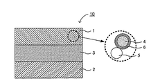
図1は、本発明の全固体電池の発電要素の一例を示す説明図である。図1に示される全固体電池の発電要素10は、正極活物質層1と、負極活物質層2と、正極活物質層1および負極活物質層2の間に形成された固体電解質層3とを有する。さらに、正極活物質層1は、正極活物質4と、架橋カルコゲン(例えば架橋硫黄)を有する架橋カルコゲン含有固体電解質材料5と、正極活物質4および架橋カルコゲン含有固体電解質材料5の界面に形成された反応抑制部6とを有する。図1において、反応抑制部6は、正極活物質4の表面を被覆するように形成されており、さらに、第4族金属元素の酸化物(例えばLi4Ti5O12)からなるものである。
FIG. 1 is an explanatory diagram showing an example of the power generation element of the all solid state battery of the present invention. 1 includes a positive electrode
本発明によれば、反応抑制部が、電気化学的安定性の高い第4族金属元素の酸化物から構成されているため、反応抑制部が、正極活物質および架橋カルコゲン含有固体電解質材料と反応することを抑制することができる。これにより、正極活物質と、架橋カルコゲン含有固体電解質材料との界面抵抗の経時的な増加を抑制することができ、その結果、耐久性に優れた全固体電池とすることができる。また、本発明によれば、架橋カルコゲン含有固体電解質材料を用いることにより、イオン伝導性を向上させることができ、電池の高出力化を図ることができる。上述したように、架橋カルコゲン含有固体電解質材料は、架橋カルコゲンの電気化学的安定性が相対的に低いため、従来の反応抑制部(例えばLiNbO3からなる反応抑制部)と反応して高抵抗層を形成しやすく、経時的な界面抵抗の増加が顕著になると考えられる。これに対して、本発明における反応抑制部は、電気化学的安定性が高いため、反応抑制部が、架橋カルコゲン含有固体電解質材料と反応しにくく、高抵抗層の生成を抑制することができる。これにより、イオン伝導性を向上させつつ、界面抵抗の経時的な増加を抑制することができると考えられる。
以下、本発明の全固体電池について、構成ごとに説明する。
According to the present invention, since the reaction suppression unit is composed of an oxide of a
Hereinafter, the all solid state battery of the present invention will be described for each configuration.
1.正極活物質層
まず、本発明における正極活物質層について説明する。本発明における正極活物質層は、少なくとも正極活物質を含有する層であり、必要に応じて、固体電解質材料および導電化材の少なくとも一方を含有していても良い。特に本発明においては、正極活物質層に含まれる固体電解質材料が、架橋カルコゲン含有固体電解質材料であることが好ましい。架橋カルコゲン含有固体電解質材料はイオン伝導性が高く、正極活物質層のイオン伝導性を向上させることができるからである。また、本発明において、正極活物質層が、正極活物質および架橋カルコゲン含有固体電解質材料の両方を含有する場合、通常、第4族金属元素の酸化物からなる反応抑制部も正極活物質層内に形成される。
1. First, the positive electrode active material layer in the present invention will be described. The positive electrode active material layer in the present invention is a layer containing at least a positive electrode active material, and may contain at least one of a solid electrolyte material and a conductive material as required. Particularly in the present invention, the solid electrolyte material contained in the positive electrode active material layer is preferably a crosslinked chalcogen-containing solid electrolyte material. This is because the crosslinked chalcogen-containing solid electrolyte material has high ionic conductivity and can improve the ionic conductivity of the positive electrode active material layer. In the present invention, when the positive electrode active material layer contains both the positive electrode active material and the cross-linked chalcogen-containing solid electrolyte material, the reaction suppression portion usually made of an oxide of a
(1)正極活物質
まず、本発明に用いられる正極活物質について説明する。本発明に用いられる正極活物質は、目的とする全固体電池の伝導イオンの種類により異なるものである。例えば、本発明の全固体電池が全固体リチウム二次電池である場合、正極活物質は、リチウムイオンを吸蔵・放出する。また、本発明に用いられる正極活物質は、通常、後述する固体電解質材料(架橋カルコゲン含有固体電解質材料)と反応し高抵抗層を形成するものである。
(1) Positive electrode active material First, the positive electrode active material used for this invention is demonstrated. The positive electrode active material used in the present invention varies depending on the type of conductive ions of the intended all-solid battery. For example, when the all solid state battery of the present invention is an all solid state lithium secondary battery, the positive electrode active material occludes and releases lithium ions. In addition, the positive electrode active material used in the present invention usually reacts with a solid electrolyte material (crosslinked chalcogen-containing solid electrolyte material) described later to form a high resistance layer.
本発明に用いられる正極活物質としては、架橋カルコゲン含有固体電解質材料と反応し高抵抗層を形成するものであれば特に限定されるものではないが、例えば酸化物系正極活物質を挙げることができる。酸化物系正極活物質を用いることにより、エネルギー密度の高い全固体電池とすることができる。全固体リチウム電池に用いられる酸化物系正極活物質としては、例えば、一般式LixMyOz(Mは遷移金属元素であり、x=0.02〜2.2、y=1〜2、z=1.4〜4)で表される正極活物質を挙げることができる。上記一般式において、Mは、Co、Mn、Ni、V、FeおよびSiからなる群から選択される少なくとも一種であることが好ましく、Co、NiおよびMnからなる群から選択される少なくとも一種であることがより好ましい。このような酸化物系正極活物質としては、具体的には、LiCoO2、LiMnO2、LiNiO2、LiVO2、LiNi1/3Co1/3Mn1/3O2、LiMn2O4、Li(Ni0.5Mn1.5)O4、Li2FeSiO4、Li2MnSiO4等を挙げることができる。また、上記一般式LixMyOz以外の正極活物質としては、LiFePO4、LiMnPO4等のオリビン型正極活物質を挙げることができる。 The positive electrode active material used in the present invention is not particularly limited as long as it reacts with the cross-linked chalcogen-containing solid electrolyte material to form a high resistance layer, and examples thereof include an oxide-based positive electrode active material. it can. By using an oxide-based positive electrode active material, an all-solid battery having a high energy density can be obtained. As an oxide type positive electrode active material used for an all solid lithium battery, for example, a general formula Li x M y O z (M is a transition metal element, x = 0.02 to 2.2, y = 1 to 2). , Z = 1.4 to 4). In the above general formula, M is preferably at least one selected from the group consisting of Co, Mn, Ni, V, Fe and Si, and is at least one selected from the group consisting of Co, Ni and Mn. It is more preferable. As such an oxide-based positive electrode active material, specifically, LiCoO 2 , LiMnO 2 , LiNiO 2 , LiVO 2 , LiNi 1/3 Co 1/3 Mn 1/3 O 2 , LiMn 2 O 4 , Li (Ni 0.5 Mn 1.5 ) O 4 , Li 2 FeSiO 4 , Li 2 MnSiO 4 and the like can be mentioned. Examples of the positive electrode active material other than the above general formula Li x M y O z include olivine-type positive electrode active materials such as LiFePO 4 and LiMnPO 4 .
正極活物質の形状としては、例えば粒子形状を挙げることができ、中でも真球状または楕円球状であることが好ましい。また、正極活物質が粒子形状である場合、その平均粒径は、例えば0.1μm〜50μmの範囲内であることが好ましい。正極活物質層における正極活物質の含有量は、例えば10重量%〜99重量%の範囲内であることが好ましく、20重量%〜90重量%の範囲内であることがより好ましい。 Examples of the shape of the positive electrode active material include a particle shape, and among them, a spherical shape or an elliptical shape is preferable. Moreover, when a positive electrode active material is a particle shape, it is preferable that the average particle diameter exists in the range of 0.1 micrometer-50 micrometers, for example. The content of the positive electrode active material in the positive electrode active material layer is, for example, preferably in the range of 10% by weight to 99% by weight, and more preferably in the range of 20% by weight to 90% by weight.
(2)架橋カルコゲン含有固体電解質材料
本発明においては、正極活物質層が、架橋カルコゲン含有固体電解質材料を含有することが好ましい。架橋カルコゲン含有固体電解質材料はイオン伝導性が高く、正極活物質層のイオン伝導性を向上させることができるからである。また、本発明に用いられる架橋カルコゲン含有固体電解質材料は、通常、上述した正極活物質と反応し高抵抗層を形成するものである。なお、高抵抗層の生成は、透過型電子顕微鏡(TEM)やエネルギー分散型X線分光法(EDX)により確認することができる。
(2) Crosslinked chalcogen-containing solid electrolyte material In the present invention, the positive electrode active material layer preferably contains a crosslinked chalcogen-containing solid electrolyte material. This is because the crosslinked chalcogen-containing solid electrolyte material has high ionic conductivity and can improve the ionic conductivity of the positive electrode active material layer. The crosslinked chalcogen-containing solid electrolyte material used in the present invention usually reacts with the above-described positive electrode active material to form a high resistance layer. The generation of the high resistance layer can be confirmed by a transmission electron microscope (TEM) or energy dispersive X-ray spectroscopy (EDX).
本発明においては、上記架橋カルコゲンが、架橋硫黄(−S−)または架橋酸素(−O−)であることが好ましく、架橋硫黄であることがより好ましい。イオン伝導性に優れた固体電解質材料とすることができるからである。架橋硫黄を有する固体電解質材料としては、例えば、Li7P3S11、0.6Li2S−0.4SiS2、0.6Li2S−0.4GeS2等を挙げることができる。ここで、上記のLi7P3S11は、PS3−S−PS3構造と、PS4構造とを有する固体電解質材料であり、PS3−S−PS3構造が架橋硫黄を有する。このように、本発明においては、架橋カルコゲン含有固体電解質材料が、PS3−S−PS3構造を有することが好ましい。本発明の効果を充分に発揮することができるからである。一方、架橋酸素を有する固体電解質材料としては、例えば、95(0.6Li2S−0.4SiS2)−5Li4SiO4、95(0.67Li2S−0.33P2S5)−5Li3PO4、95(0.6Li2S−0.4GeS2)−5Li3PO4等を挙げることができる。
In the present invention, the crosslinked chalcogen is preferably crosslinked sulfur (—S—) or crosslinked oxygen (—O—), and more preferably crosslinked sulfur. It is because it can be set as the solid electrolyte material excellent in ion conductivity. The solid electrolyte material having a crosslinked sulfur, for example, Li 7 P 3 S 11, 0.6Li 2 S-0.4
また、架橋カルコゲン含有固体電解質材料の形状としては、例えば粒子形状を挙げることができ、中でも真球状または楕円球状であることが好ましい。また、架橋カルコゲン含有固体電解質材料が粒子形状である場合、その平均粒径は、例えば0.1μm〜50μmの範囲内であることが好ましい。正極活物質層における架橋カルコゲン含有固体電解質材料の含有量は、例えば1重量%〜90重量%の範囲内であることが好ましく、10重量%〜80重量%の範囲内であることがより好ましい。 Examples of the shape of the crosslinked chalcogen-containing solid electrolyte material include a particle shape, and among them, a true spherical shape or an elliptical spherical shape is preferable. Moreover, when a bridge | crosslinking chalcogen containing solid electrolyte material is a particle shape, it is preferable that the average particle diameter exists in the range of 0.1 micrometer-50 micrometers, for example. The content of the crosslinked chalcogen-containing solid electrolyte material in the positive electrode active material layer is, for example, preferably in the range of 1% by weight to 90% by weight, and more preferably in the range of 10% by weight to 80% by weight.
(3)反応抑制部
本発明において、正極活物質層が、正極活物質および架橋カルコゲン含有固体電解質材料の両方を含有する場合、通常、第4族金属元素の酸化物からなる反応抑制部も正極活物質層内に形成される。これは、反応抑制部が、正極活物質と、架橋カルコゲン含有固体電解質材料との界面に形成される必要があるからである。反応抑制部は、電池使用時に生じる、正極活物質と、架橋カルコゲン含有固体電解質材料との反応を抑制する機能を有する。反応抑制部を構成する第4族金属元素の酸化物は、従来のニオブ酸化物(例えばLiNbO3)と比較して、電気化学的安定性が高いため、界面抵抗の経時的な増加を抑制することができる。
(3) Reaction Inhibiting Portion In the present invention, when the positive electrode active material layer contains both the positive electrode active material and the cross-linked chalcogen-containing solid electrolyte material, the reaction suppressing portion composed of an oxide of a
まず、反応抑制部を構成する第4族金属元素の酸化物について説明する。本発明における第4族金属元素の酸化物は、少なくとも、第4族金属元素と、その金属元素に結合した酸素元素とを有するものである。本発明においては、上記第4族金属元素が、チタンまたはジルコニウムであることが好ましい。電気化学的安定性の高い酸化物が得られ、汎用的な遷移金属元素だからである。このような第4族金属元素の酸化物としては、例えば、TiO2およびZrO2等を挙げることができる。また、第4族金属元素の酸化物は、チタンおよびジルコニウムの両方を有するものであっても良い。
First, an oxide of a
本発明においては、第4族金属元素の酸化物が、さらに伝導イオンとなる金属元素を含むことが好ましい。イオン伝導性に優れた酸化物とすることができるからである。上記金属元素は、目的とする全固体電池の種類に応じて異なるものであるが、例えば、LiおよびNa等のアルカリ金属元素、並びに、MgおよびCa等のアルカリ土類金属元素等を挙げることができ、中でもアルカリ金属元素が好ましく、特にLiが好ましい。すなわち、本発明の全固体電池が全固体リチウム電池である場合は、第4族金属元素の酸化物が、さらにLiを含有することが好ましい。Liを有する第4族金属元素の酸化物としては、例えば、Li4Ti5O12、LiTiO3、Li2ZrO3等を挙げることができる。
In this invention, it is preferable that the oxide of a
また、正極活物質層における第4族金属元素の酸化物の含有量としては、例えば0.1重量%〜20重量%の範囲内であることが好ましく、0.5重量%〜10重量%の範囲内であることがより好ましい。
Moreover, as content of the oxide of the
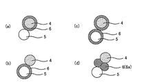
次に、正極活物質層における反応抑制部の形態について説明する。本発明において、正極活物質層が、架橋カルコゲン含有固体電解質材料を含有する場合、第4族金属元素の酸化物からなる反応抑制部は、通常、正極活物質層内に形成される。この場合における反応抑制部の形態としては、例えば図2に示すように、反応抑制部6が正極活物質4の表面を被覆するように形成される形態(図2(a))、反応抑制部6が、架橋カルコゲン含有固体電解質材料5の表面を被覆するように形成される形態(図2(b))、反応抑制部6が、正極活物質4および架橋カルコゲン含有固体電解質材料5の表面を被覆するように形成される形態(図2(c))等を挙げることができる。中でも、本発明においては、反応抑制部が、正極活物質の表面を被覆するように形成されていることが好ましい。正極活物質は、架橋カルコゲン含有固体電解質材料と比較して硬いため、被覆された反応抑制部が剥離されにくくなるからである。
Next, the form of the reaction suppression part in a positive electrode active material layer is demonstrated. In the present invention, when the positive electrode active material layer contains a cross-linked chalcogen-containing solid electrolyte material, the reaction suppressing portion made of a
なお、正極活物質と、架橋カルコゲン含有固体電解質材料と、第4族金属元素の酸化物とを単に混合しただけでも、図2(d)に示すように、正極活物質4と、架橋カルコゲン含有固体電解質材料5との界面に、第4族金属元素の酸化物6aが配置され、反応抑制部6を形成することができる。この場合、界面抵抗の経時的な増加を抑制する効果は若干劣るものの、正極活物質層の製造工程が簡略化されるという利点を有する。
As shown in FIG. 2D, the positive electrode active material, the cross-linked chalcogen-containing solid electrolyte material, and the oxide of the
また、正極活物質または架橋カルコゲン含有固体電解質材料を被覆する反応抑制部の厚さは、これらの材料が反応を生じない程度の厚さであることが好ましく、例えば1nm〜500nmの範囲内であることが好ましく、2nm〜100nmの範囲内であることがより好ましい。反応抑制部の厚さが小さすぎると、正極活物質と架橋カルコゲン含有固体電解質材料とが反応する可能性があり、反応抑制部の厚さが大きすぎると、イオン伝導性が低下する可能性があるからである。また、反応抑制部は、正極活物質等のより多くの面積を被覆していることが好ましく、正極活物質等の表面の全てを被覆していることがより好ましい。界面抵抗の経時的な増加を効果的に抑制することができるからである。 In addition, the thickness of the reaction suppressing portion that covers the positive electrode active material or the crosslinked chalcogen-containing solid electrolyte material is preferably such a thickness that these materials do not cause a reaction, for example, in the range of 1 nm to 500 nm. Preferably, it is in the range of 2 nm to 100 nm. If the thickness of the reaction suppression portion is too small, the positive electrode active material and the crosslinked chalcogen-containing solid electrolyte material may react, and if the thickness of the reaction suppression portion is too large, the ion conductivity may decrease. Because there is. Moreover, it is preferable that the reaction suppression part coat | covers more areas, such as a positive electrode active material, and it is more preferable to coat | cover all the surfaces, such as a positive electrode active material. This is because an increase in the interfacial resistance with time can be effectively suppressed.
本発明における反応抑制部の形成方法は、上述した反応抑制部の形態に応じて、適宜選択することが好ましい。例えば、正極活物質を被覆する反応抑制部を形成する場合は、反応抑制部の形成方法として、第4族金属元素を含む原料化合物を有する原料組成物を正極活物質に塗布し、次に、原料組成物が塗布された正極活物質に、大気中で熱処理を加える方法等を挙げることができる。原料組成物の塗布方法としては、例えば、転動流動層を有するコート装置を用いる方法等を挙げることができる。また、反応抑制部の形成方法の他の例として、メカノフュージョン法、CVD法、PVD法等を挙げることができる。
The method for forming the reaction suppression unit in the present invention is preferably selected as appropriate according to the form of the reaction suppression unit described above. For example, when forming a reaction suppression part that covers the positive electrode active material, as a method for forming the reaction suppression part, a raw material composition having a raw material compound containing a
(4)正極活物質層
本発明における正極活物質層は、さらに導電化材を含有していても良い。導電化材の添加により、正極活物質層の導電性を向上させることができる。導電化材としては、例えばアセチレンブラック、ケッチェンブラック、カーボンファイバー等を挙げることができる。また、正極活物質層における導電化材の含有量は、特に限定されるものではないが、例えば0.1重量%〜20重量%の範囲内であることが好ましい。また、正極活物質層の厚さは、目的とする全固体電池の種類によって異なるものであるが、例えば1μm〜100μmの範囲内であることが好ましい。
(4) Positive electrode active material layer The positive electrode active material layer in the present invention may further contain a conductive material. By adding a conductive material, the conductivity of the positive electrode active material layer can be improved. Examples of the conductive material include acetylene black, ketjen black, and carbon fiber. Further, the content of the conductive material in the positive electrode active material layer is not particularly limited, but is preferably in the range of 0.1 wt% to 20 wt%, for example. Moreover, although the thickness of a positive electrode active material layer changes with kinds of the target all-solid-state battery, it is preferable to exist in the range of 1 micrometer-100 micrometers, for example.
2.固体電解質層
次に、本発明における固体電解質層について説明する。本発明における固体電解質層は、少なくとも固体電解質材料を含有する層である。上述したように、正極活物質層が、架橋カルコゲン含有固体電解質材料を含有する場合、固体電解質層に用いられる固体電解質材料は、特に限定されるものではなく、架橋カルコゲン含有固体電解質材料であっても良く、それ以外の固体電解質材料であっても良い。一方、正極活物質層が、架橋カルコゲン含有固体電解質材料を含有しない場合、通常、固体電解質層は、架橋カルコゲン含有固体電解質材料を含有する。特に、本発明においては、正極活物質層および固体電解質層の両方が、架橋カルコゲン含有固体電解質材料を含有することが好ましい。イオン伝導性に優れた全固体電池とすることができるからである。また、固体電解質層に用いられる固体電解質材料は、架橋カルコゲン含有固体電解質材料のみであることが好ましい。
2. Next, the solid electrolyte layer in the present invention will be described. The solid electrolyte layer in the present invention is a layer containing at least a solid electrolyte material. As described above, when the positive electrode active material layer contains a crosslinked chalcogen-containing solid electrolyte material, the solid electrolyte material used for the solid electrolyte layer is not particularly limited, and is a crosslinked chalcogen-containing solid electrolyte material. Alternatively, other solid electrolyte materials may be used. On the other hand, when the positive electrode active material layer does not contain a crosslinked chalcogen-containing solid electrolyte material, the solid electrolyte layer usually contains a crosslinked chalcogen-containing solid electrolyte material. In particular, in the present invention, it is preferable that both the positive electrode active material layer and the solid electrolyte layer contain a crosslinked chalcogen-containing solid electrolyte material. It is because it can be set as the all-solid-state battery excellent in ion conductivity. The solid electrolyte material used for the solid electrolyte layer is preferably only a crosslinked chalcogen-containing solid electrolyte material.
なお、架橋カルコゲン含有固体電解質材料については、上記「1.正極活物質層」に記載した内容と同様である。また、架橋カルコゲン含有固体電解質材料以外の固体電解質材料については、一般的な全固体電池に用いられる固体電解質材料と同様の材料を用いることができ、例えば、硫化物系固体電解質材料および酸化物系固体電解質材料等を挙げることができる。 In addition, about the bridge | crosslinking chalcogen containing solid electrolyte material, it is the same as that of the content described in the said "1. positive electrode active material layer". In addition, as for the solid electrolyte material other than the crosslinked chalcogen-containing solid electrolyte material, the same material as the solid electrolyte material used in a general all-solid battery can be used, for example, a sulfide-based solid electrolyte material and an oxide-based material. Examples thereof include solid electrolyte materials.
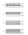
本発明において、固体電解質層が、架橋カルコゲン含有固体電解質材料を含有する場合、第4族金属元素の酸化物からなる反応抑制部は、通常、正極活物質層内、固体電解質層内、または正極活物質層および固体電解質層の界面に形成される。この場合における反応抑制部の形態としては、例えば図3に示すように、反応抑制部6が、正極活物質4を含む正極活物質層1と、架橋カルコゲン含有固体電解質材料5を含む固体電解質層3との界面に形成される形態(図3(a))、反応抑制部6が、正極活物質4の表面を被覆するように形成される形態(図3(b))、反応抑制部6が、架橋カルコゲン含有固体電解質材料5の表面を被覆するように形成される形態(図3(c))、反応抑制部6が、正極活物質4、および架橋カルコゲン含有固体電解質材料5の表面を被覆するように形成される形態(図3(d))等を挙げることができる。中でも、本発明においては、反応抑制部が、正極活物質の表面を被覆するように形成されていることが好ましい。正極活物質は、架橋カルコゲン含有固体電解質材料と比較して硬いため、被覆された反応抑制部が剥離されにくくなるからである。
In the present invention, when the solid electrolyte layer contains a cross-linked chalcogen-containing solid electrolyte material, the reaction suppressing portion made of an oxide of a
本発明における固体電解質層の厚さは、例えば0.1μm〜1000μmの範囲内、中でも0.1μm〜300μmの範囲内であることが好ましい。 The thickness of the solid electrolyte layer in the present invention is, for example, preferably in the range of 0.1 μm to 1000 μm, and more preferably in the range of 0.1 μm to 300 μm.
3.負極活物質層
次に、本発明における負極活物質層について説明する。本発明における負極活物層は、少なくとも負極活物質を含有する層であり、必要に応じて、固体電解質材料および導電化材の少なくとも一方を含有していても良い。負極活物質としては、目的とする全固体電池の伝導イオンの種類により異なるものであるが、例えば金属活物質およびカーボン活物質を挙げることができる。金属活物質としては、例えばIn、Al、SiおよびSn等を挙げることができる。一方、カーボン活物質としては、例えばメソカーボンマイクロビーズ(MCMB)、高配向性グラファイト(HOPG)、ハードカーボン、ソフトカーボン等を挙げることができる。なお、負極活物質層に用いられる固体電解質材料および導電化材については、上述した正極活物質層における場合と同様である。また、負極活物質層の厚さは、例えば0.1μm〜1000μmの範囲内である。
3. Next, the negative electrode active material layer in the present invention will be described. The negative electrode active material layer in the present invention is a layer containing at least a negative electrode active material, and may contain at least one of a solid electrolyte material and a conductive material as required. The negative electrode active material varies depending on the type of conductive ions of the target all-solid battery, and examples thereof include a metal active material and a carbon active material. Examples of the metal active material include In, Al, Si, and Sn. On the other hand, examples of the carbon active material include mesocarbon microbeads (MCMB), highly oriented graphite (HOPG), hard carbon, and soft carbon. In addition, about the solid electrolyte material and electroconductive material used for a negative electrode active material layer, it is the same as that of the case in the positive electrode active material layer mentioned above. The thickness of the negative electrode active material layer is, for example, in the range of 0.1 μm to 1000 μm.
4.その他の構成
本発明の全固体電池は、上述した正極活物質層、固体電解質層および負極活物質層を少なくとも有するものである。さらに通常は、正極活物質層の集電を行う正極集電体、および負極活物質の集電を行う負極集電体を有する。正極集電体の材料としては、例えばSUS、アルミニウム、ニッケル、鉄、チタンおよびカーボン等を挙げることができ、中でもSUSが好ましい。一方、負極集電体の材料としては、例えばSUS、銅、ニッケルおよびカーボン等を挙げることができ、中でもSUSが好ましい。また、正極集電体および負極集電体の厚さや形状等については、全固体電池の用途等に応じて適宜選択することが好ましい。また、本発明に用いられる電池ケースには、一般的な全固体電池の電池ケースを用いることができる。電池ケースとしては、例えばSUS製電池ケース等を挙げることができる。また、本発明の全固体電池は、発電要素を絶縁リングの内部に形成したものであっても良い。
4). Other Configurations The all solid state battery of the present invention has at least the positive electrode active material layer, the solid electrolyte layer, and the negative electrode active material layer described above. Furthermore, it usually has a positive electrode current collector for collecting current of the positive electrode active material layer and a negative electrode current collector for collecting current of the negative electrode active material. Examples of the material for the positive electrode current collector include SUS, aluminum, nickel, iron, titanium, and carbon. Among them, SUS is preferable. On the other hand, examples of the material for the negative electrode current collector include SUS, copper, nickel, and carbon. Of these, SUS is preferable. In addition, the thickness and shape of the positive electrode current collector and the negative electrode current collector are preferably appropriately selected according to the use of the all solid state battery. Moreover, the battery case of a general all-solid-state battery can be used for the battery case used for this invention. Examples of the battery case include a SUS battery case. Further, the all solid state battery of the present invention may be one in which the power generating element is formed inside the insulating ring.
5.全固体電池
本発明においては、電気化学的安定性の高い第4族金属元素の酸化物からなる反応抑制部を用いているため、伝導イオンの種類は特に限定されるものではない。本発明の全固体電池の種類としては、全固体リチウム電池、全固体ナトリウム電池、全固体マグネシウム電池および全固体カルシウム電池等を挙げることができ、中でも、全固体リチウム電池および全固体ナトリウム電池が好ましく、特に、全固体リチウム電池が好ましい。また、本発明の全固体電池は、一次電池であっても良く、二次電池であっても良いが、中でも、二次電池であることが好ましい。繰り返し充放電でき、例えば車載用電池として有用だからである。本発明の全固体電池の形状としては、例えば、コイン型、ラミネート型、円筒型および角型等を挙げることができ、中でも角型およびラミネート型が好ましく、特にラミネート型が好ましい。
5). All-solid-state battery In this invention, since the reaction suppression part which consists of an oxide of the
また、本発明の全固体電池の製造方法は、上述した全固体電池を得ることができる方法であれば特に限定されるものではなく、一般的な全固体電池の製造方法と同様の方法を用いることができる。全固体電池の製造方法の一例としては、正極活物質層を構成する材料、固体電解質層を構成する材料、および負極活物質層を構成する材料を順次プレスすることにより、発電要素を作製し、この発電要素を電池ケースの内部に収納し、電池ケースをかしめる方法等を挙げることができる。 Moreover, the manufacturing method of the all-solid-state battery of this invention will not be specifically limited if it is a method which can obtain the all-solid-state battery mentioned above, The method similar to the manufacturing method of a general all-solid-state battery is used. be able to. As an example of a method for producing an all-solid-state battery, a power generation element is manufactured by sequentially pressing a material constituting the positive electrode active material layer, a material constituting the solid electrolyte layer, and a material constituting the negative electrode active material layer, A method of storing the power generation element in the battery case and caulking the battery case can be exemplified.
なお、本発明は、上記実施形態に限定されるものではない。上記実施形態は、例示であり、本発明の特許請求の範囲に記載された技術的思想と実質的に同一な構成を有し、同様な作用効果を奏するものは、いかなるものであっても本発明の技術的範囲に包含される。 The present invention is not limited to the above embodiment. The above-described embodiment is an exemplification, and the present invention has substantially the same configuration as the technical idea described in the claims of the present invention, and any device that exhibits the same function and effect is the present invention. It is included in the technical scope of the invention.
以下に実施例を示して本発明をさらに具体的に説明する。 Hereinafter, the present invention will be described in more detail with reference to examples.
[実施例1]
(LiCoO2をLi4Ti5O12で被覆した材料の作製)
まず、エタノール中で、リチウムエトキシドおよびチタンイソプロポキシドを、モル比4:5の割合で混合した。次に、得られた溶液を、転動流動層を用いたコート装置にて、正極活物質(LiCoO2)上に、厚さが5nmになるように塗布し、温風で乾燥させた。次に、得られた粉末を、大気中、400℃の条件で30分間熱処理し、LiCoO2をLi4Ti5O12で被覆した材料を得た。次に、得られた材料と、Li7P3S11とを、重量比7:3で混合し、正極合材を得た。
[Example 1]
(Preparation of a material in which LiCoO 2 is coated with Li 4 Ti 5 O 12 )
First, in ethanol, lithium ethoxide and titanium isopropoxide were mixed at a molar ratio of 4: 5. Next, the obtained solution was applied on the positive electrode active material (LiCoO 2 ) so as to have a thickness of 5 nm by a coating apparatus using a rolling fluidized bed, and dried with hot air. Next, the obtained powder was heat-treated in the atmosphere at 400 ° C. for 30 minutes to obtain a material in which LiCoO 2 was coated with Li 4 Ti 5 O 12 . Next, the obtained material and Li 7 P 3 S 11 were mixed at a weight ratio of 7: 3 to obtain a positive electrode mixture.
(全固体リチウム二次電池の作製)
まず、特開2005−228570号公報に記載された方法と同様の方法で、Li7P3S11(架橋硫黄を有する固体電解質材料)を得た。なお、Li7P3S11は、PS3−S−PS3構造と、PS4構造とを有する固体電解質材料である。次に、プレス機を用いて、上述した図1に示すような発電要素10を作製した。正極活物質層1を構成する材料として上記の正極合材を用い、負極活物質層2を構成する材料としてIn箔を用い、固体電解質層3を構成する材料としてLi7P3S11を用いた。この発電要素を用いて、全固体リチウム二次電池を得た。
(Preparation of all-solid lithium secondary battery)
First, Li 7 P 3 S 11 (solid electrolyte material having bridging sulfur) was obtained by a method similar to the method described in JP-A-2005-228570. Li 7 P 3 S 11 is a solid electrolyte material having a PS 3 —S—PS 3 structure and a PS 4 structure. Next, the electric power generation element 10 as shown in FIG. 1 mentioned above was produced using the press machine. The above positive electrode mixture is used as the material constituting the positive electrode
[比較例1]
チタンテトライソプロポキシドの代わりにニオブペンタエトキシドを用い、ニオブペンタエトキシドとリチウムエトキシドとのモル比を1:1としたこと以外(LiCoO2をLiNbO3で被覆した材料を作製したこと以外)は、実施例1と同様にして、全固体リチウム二次電池を得た。
[Comparative Example 1]
Niobium pentaethoxide was used instead of titanium tetraisopropoxide, and the molar ratio of niobium pentaethoxide to lithium ethoxide was 1: 1 (except that a material in which LiCoO 2 was coated with LiNbO 3 was prepared) ) In the same manner as in Example 1 to obtain an all-solid lithium secondary battery.
[評価1]
実施例1および比較例1で得られた全固体リチウム二次電池に対して、放電容量維持率および界面抵抗変化率の測定、並びに界面のTEM観察を行った。
[Evaluation 1]
The all-solid lithium secondary batteries obtained in Example 1 and Comparative Example 1 were measured for discharge capacity retention rate and interface resistance change rate, and TEM observation of the interface.
(放電容量維持率および界面抵抗変化率の測定)
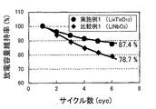
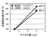
まず、全固体リチウム二次電池の充電を行った。充電条件は、0.1Cで3.34Vまで定電流充電し、その後、3.34Vでの定電圧充電を2時間行うものとした。充電後、インピーダンス測定により、正極活物質層および固体電解質層の界面抵抗を求めた。インピーダンス測定の条件は、電圧振幅10mV,測定周波数1MHz〜0.1Hz、25℃とした。その後、放電条件(0.1Cの定電流で2Vまで)および充電条件(0.1Cの定電流で3.58Vまで)で、6サイクルの充放電を行った。放電容量維持率の結果を図4に示す。また、最初の充電後の界面抵抗値と、6サイクル目の充電後の界面抵抗値とから、界面抵抗変化率を求めた。その結果を、図5に示す。
(Measurement of discharge capacity retention rate and interface resistance change rate)
First, the all solid lithium secondary battery was charged. The charging conditions were as follows: constant current charging at 0.1 C to 3.34 V, and then constant voltage charging at 3.34 V for 2 hours. After charging, the interface resistance between the positive electrode active material layer and the solid electrolyte layer was determined by impedance measurement. The impedance measurement conditions were a voltage amplitude of 10 mV, a measurement frequency of 1 MHz to 0.1 Hz, and 25 ° C. Thereafter, 6 cycles of charge and discharge were performed under discharge conditions (up to 2 V at a constant current of 0.1 C) and charging conditions (up to 3.58 V at a constant current of 0.1 C). The results of the discharge capacity retention rate are shown in FIG. Further, the rate of change in interface resistance was determined from the interface resistance value after the first charge and the interface resistance value after the 6th charge. The result is shown in FIG.
図4および図5に示されるように、実施例1の全固体リチウム二次電池は、比較例1の全固体リチウム二次電池に比べて、放電容量維持率および界面抵抗変化率の結果が良好であった。これは、実施例1で用いたLi4Ti5O12が、比較例1で用いたLiNbO3よりも電気化学的安定性が高く、反応抑制部としての機能が高いからであると考えられる。 As shown in FIGS. 4 and 5, the all-solid lithium secondary battery of Example 1 has better discharge capacity retention rate and interface resistance change rate than the all-solid lithium secondary battery of Comparative Example 1. Met. This is presumably because Li 4 Ti 5 O 12 used in Example 1 has higher electrochemical stability than LiNbO 3 used in Comparative Example 1, and has a high function as a reaction suppression unit.
(界面のTEM観察)
上記の充放電が終了した後、全固体リチウム二次電池を解体し、正極活物質と、架橋カルコゲン含有固体電解質材料との界面を、TEM(透過型電子顕微鏡)を用いて観察した。その結果、比較例1で得られた全固体リチウム二次電池では、正極活物質(LiCoO2)と、架橋カルコゲン含有固体電解質材料(Li7P3S11)との界面に存在する反応抑制部(LiNbO3)に、高抵抗層が形成されていることが確認された。これに対して、実施例1で得られた全固体リチウム二次電池では、反応抑制部(Li4Ti5O12)には、高抵抗層の形成が確認されなかった。これにより、Li4Ti5O12が、LiCoO2およびLi7P3S11に対して、安定であることが確認できた。
(Interface TEM observation)
After completion of the above charge / discharge, the all-solid lithium secondary battery was disassembled, and the interface between the positive electrode active material and the crosslinked chalcogen-containing solid electrolyte material was observed using a TEM (transmission electron microscope). As a result, in the all-solid-state lithium secondary battery obtained in Comparative Example 1, the reaction suppression unit present at the interface between the positive electrode active material (LiCoO 2 ) and the crosslinked chalcogen-containing solid electrolyte material (Li 7 P 3 S 11 ). It was confirmed that a high resistance layer was formed on (LiNbO 3 ). On the other hand, in the all solid lithium secondary battery obtained in Example 1, formation of a high resistance layer was not confirmed in the reaction suppression portion (Li 4 Ti 5 O 12 ). Thus, Li 4 Ti 5 O 12 is, with respect to LiCoO 2 and Li 7 P 3 S 11, it was confirmed to be stable.
[実施例2]
実施例2においては、第4族金属元素の酸化物(Li4Ti5O12)および正極活物質(LiCoO2)の経時的な反応性、並びに、第4族金属元素の酸化物(Li4Ti5O12)および架橋カルコゲン含有固体電解質材料(Li7P3S11)の経時的な反応性を評価した。ここでは、これらの材料に機械的エネルギーおよび熱エネルギーを加える手法で、これらの材料の界面状態を評価した。
[Example 2]
In Example 2, reactivity of
まず、Li4Ti5O12およびLiCoO2を体積比1:1でポットに投入し、回転数150rpm、20時間の条件でボールミルを行った。次に、得られた粉末を、Ar雰囲気、120℃、2週間の条件で熱処理し、評価用サンプルを得た(実施例2−1)。また、LiCoO2の代わりに、Li7P3S11を用いたこと以外は、実施例2−1と同様にして、評価用サンプルを得た(実施例2−2)。 First, Li 4 Ti 5 O 12 and LiCoO 2 were charged into the pot at a volume ratio of 1: 1, and ball milling was performed under the conditions of a rotation speed of 150 rpm and 20 hours. Next, the obtained powder was heat-treated under conditions of Ar atmosphere, 120 ° C., and 2 weeks to obtain a sample for evaluation (Example 2-1). Further, in place of LiCoO 2, Li 7 P 3 except for using S 11, the same procedure as in Example 2-1, to obtain an evaluation sample (Example 2-2).
[比較例2]
Li4Ti5O12の代わりに、LiNbO3を用いたこと以外は、実施例2−1および実施例2−2と同様にして、評価用サンプルを得た(比較例2−1、比較例2−2)。
[Comparative Example 2]
Samples for evaluation were obtained in the same manner as in Example 2-1 and Example 2-2 except that LiNbO 3 was used instead of Li 4 Ti 5 O 12 (Comparative Example 2-1, Comparative Example). 2-2).
[比較例3]
比較例3においては、正極活物質(LiCoO2)および架橋カルコゲン含有固体電解質材料(Li7P3S11)の反応性を評価した。具体的には、LiCoO2およびLi7P3S11を体積比1:1としたこと以外は、実施例2−1と同様にして、評価用サンプルを得た(比較例3−1)。また、LiCoO2およびLi7P3S11を、比較例3−1と同じ割合で混合し、評価用サンプルを得た(比較例3−2)。
[Comparative Example 3]
In Comparative Example 3, the reactivity of the positive electrode active material (LiCoO 2 ) and the crosslinked chalcogen-containing solid electrolyte material (Li 7 P 3 S 11 ) was evaluated. Specifically, a sample for evaluation was obtained in the same manner as Example 2-1 except that LiCoO 2 and Li 7 P 3 S 11 were set to a volume ratio of 1: 1 (Comparative Example 3-1). Furthermore, the LiCoO 2 and Li 7 P 3 S 11, were mixed in the same proportions as Comparative Example 3-1, to obtain a sample for evaluation (Comparative Example 3-2).
[評価2]
実施例2、比較例2、3で得られた評価用サンプルを用いて、X線回折(XRD)測定を行った。その結果を図6〜図8示す。図6(a)、(b)に示すように、Li4Ti5O12は、LiCoO2およびLi7P3S11のいずれに対しても、反応相を形成しないことが確認された。これは、Li4Ti5O12(第4族金属元素の酸化物)の電気化学的安定性が高いことに起因するものであると考えられる。これに対して、図7(a)、(b)に示すように、LiNbO3は、LiCoO2と反応することでCoO(NbO)が生成し、Li7P3S11と反応することでNbOやSを生成することが確認された。この結果から、これらの反応生成物が界面抵抗を増加させる高抵抗層として機能することが考えられる。また、図8(a)、(b)に示すように、LiCoO2およびLi7P3S11が反応すると、Co9S8、CoSおよびCoSO4等が生成することが確認された。この結果からも、これらの反応生成物が界面抵抗を増加させる高抵抗層として機能することが考えられる。
[Evaluation 2]
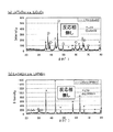
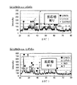
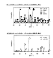
X-ray diffraction (XRD) measurement was performed using the samples for evaluation obtained in Example 2 and Comparative Examples 2 and 3. The results are shown in FIGS. As shown in FIGS. 6A and 6B, it was confirmed that Li 4 Ti 5 O 12 did not form a reaction phase with respect to any of LiCoO 2 and Li 7 P 3 S 11 . This is considered to be caused by the high electrochemical stability of Li 4 Ti 5 O 12 (
[参考例]
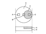
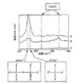
参考例においては、正極活物質と、架橋カルコゲン含有固体電解質材料との界面の状態を、ラマン分光スペクトル法により観察した。まず、正極活物質としてLiCoO2を用意し、架橋カルコゲン含有固体電解質材料として、実施例1で合成したLi7P3S11を用意し、図9に示すように、架橋カルコゲン含有固体電解質材料5の一部に正極活物質4が組み込まれた2相ペレットを作製した。その後、架橋カルコゲン含有固体電解質材料5の領域である領域A、架橋カルコゲン含有固体電解質材料5および正極活物質4の界面領域である領域B、正極活物質4の領域である領域Cにおいて、ラマン分光スペクトルを測定した。その結果を図10に示す。
[Reference example]
In the reference example, the state of the interface between the positive electrode active material and the crosslinked chalcogen-containing solid electrolyte material was observed by Raman spectroscopy. First, LiCoO 2 was prepared as a positive electrode active material, Li 7 P 3 S 11 synthesized in Example 1 was prepared as a crosslinked chalcogen-containing solid electrolyte material, and as shown in FIG. 9, the crosslinked chalcogen-containing
図10において、402cm−1のピークはPS3−S−PS3構造のピークであり、417cm−1のピークはPS4構造のピークである。領域Aにおいて、402cm−1および417cm−1のピークは大きく検出されるのに対して、領域Bにおいて、これらのピークはいずれも小さくなっており、特に402cm−1のピーク(PS3−S−PS3構造のピーク)の減少は顕著であった。これらのことから、リチウムイオン伝導に大きく寄与するPS3−S−PS3構造が破壊されやすいことが確認された。また、このような固体電解質材料を用いることで、本発明の効果を充分に発揮できることが示唆された。 In FIG. 10, the peak at 402 cm −1 is the peak of the PS 3 —S—PS 3 structure, and the peak at 417 cm −1 is the peak of the PS 4 structure. In the region A, the peaks at 402 cm −1 and 417 cm −1 are greatly detected, whereas in the region B, both of these peaks are small, and in particular, the peak at 402 cm −1 (PS 3 —S— The decrease in the peak of the PS 3 structure was significant. From these results, it was confirmed that the PS 3 —S—PS 3 structure, which greatly contributes to lithium ion conduction, is easily destroyed. Moreover, it was suggested that the effect of this invention can fully be exhibited by using such a solid electrolyte material.
1 … 正極活物質層
2 … 負極活物質層
3 … 固体電解質層
4 … 正極活物質
5 … 架橋カルコゲン含有固体電解質材料
6 … 反応抑制部
10 … 全固体電池の発電要素
DESCRIPTION OF
Claims (10)
前記正極活物質と、架橋カルコゲンを有する架橋カルコゲン含有固体電解質材料との界面に、第4族金属元素の酸化物からなる反応抑制部が形成されていることを特徴とする全固体電池。 An all solid having a positive electrode active material layer containing a positive electrode active material, a negative electrode active material layer containing a negative electrode active material, and a solid electrolyte layer formed between the positive electrode active material layer and the negative electrode active material layer A battery,
An all-solid battery, wherein a reaction suppression portion made of an oxide of a Group 4 metal element is formed at an interface between the positive electrode active material and a crosslinked chalcogen-containing solid electrolyte material having a crosslinked chalcogen.
Priority Applications (1)
| Application Number | Priority Date | Filing Date | Title |
|---|---|---|---|
| JP2008325282A JP2010146936A (en) | 2008-12-22 | 2008-12-22 | All-solid battery |
Applications Claiming Priority (1)
| Application Number | Priority Date | Filing Date | Title |
|---|---|---|---|
| JP2008325282A JP2010146936A (en) | 2008-12-22 | 2008-12-22 | All-solid battery |
Publications (1)
| Publication Number | Publication Date |
|---|---|
| JP2010146936A true JP2010146936A (en) | 2010-07-01 |
Family
ID=42567112
Family Applications (1)
| Application Number | Title | Priority Date | Filing Date |
|---|---|---|---|
| JP2008325282A Pending JP2010146936A (en) | 2008-12-22 | 2008-12-22 | All-solid battery |
Country Status (1)
| Country | Link |
|---|---|
| JP (1) | JP2010146936A (en) |
Cited By (10)
| Publication number | Priority date | Publication date | Assignee | Title |
|---|---|---|---|---|
| WO2012164724A1 (en) * | 2011-06-02 | 2012-12-06 | トヨタ自動車株式会社 | Solid electrolyte material, solid cell, and method for manufacturing solid electrolyte material |
| JP2013089321A (en) * | 2011-10-13 | 2013-05-13 | Samsung Yokohama Research Institute Co Ltd | Lithium ion secondary battery and method for producing positive electrode active material for lithium ion secondary battery |
| EP2609652A2 (en) | 2010-08-26 | 2013-07-03 | Toyota Jidosha Kabushiki Kaisha | Sulfide solid electrolyte material, cathode body and lithium solid state battery |
| US8968939B2 (en) | 2009-05-01 | 2015-03-03 | Toyota Jidosha Kabushiki Kaisha | Solid electrolyte material, electrode element that includes solid electrolyte material, all-solid battery that includes solid electrolyte material, and manufacturing method for solid electrolyte material |
| JPWO2013046443A1 (en) * | 2011-09-30 | 2015-03-26 | トヨタ自動車株式会社 | All-solid battery and method for manufacturing the same |
| JP2015201372A (en) * | 2014-04-09 | 2015-11-12 | 出光興産株式会社 | Method for producing active material composite |
| JP2016024916A (en) * | 2014-07-17 | 2016-02-08 | トヨタ自動車株式会社 | Electrode for all-solid battery and method for producing the same |
| US10340506B2 (en) | 2014-11-28 | 2019-07-02 | Samsung Electronics Co., Ltd. | Positive electrode for lithium ion secondary battery and lithium ion secondary battery including the same |
| CN110121799A (en) * | 2016-12-16 | 2019-08-13 | 株式会社日立制作所 | Electrode for secondary battery, secondary battery, and their manufacturing method |
| CN115699211A (en) * | 2020-06-10 | 2023-02-03 | 昭和电工株式会社 | Solid electrolyte material, solid electrolyte, method for manufacturing solid electrolyte, and all-solid battery |
Citations (7)
| Publication number | Priority date | Publication date | Assignee | Title |
|---|---|---|---|---|
| JPH11219722A (en) * | 1998-02-03 | 1999-08-10 | Matsushita Electric Ind Co Ltd | Lithium secondary battery |
| JP2001328816A (en) * | 2000-05-19 | 2001-11-27 | National Institute For Materials Science | Cubic lithium iron chloride, method for producing the same, and lithium secondary battery using the same |
| WO2007004590A1 (en) * | 2005-07-01 | 2007-01-11 | National Institute For Materials Science | All-solid lithium battery |
| JP2008091328A (en) * | 2006-09-04 | 2008-04-17 | Sumitomo Electric Ind Ltd | Lithium secondary battery and manufacturing method thereof |
| JP2008103146A (en) * | 2006-10-18 | 2008-05-01 | Idemitsu Kosan Co Ltd | Solid electrolyte and secondary battery using the same |
| JP2008103204A (en) * | 2006-10-19 | 2008-05-01 | Idemitsu Kosan Co Ltd | Positive electrode active material and secondary battery using the same |
| JP2008103280A (en) * | 2006-10-20 | 2008-05-01 | Idemitsu Kosan Co Ltd | Positive electrode mixture and all-solid-state secondary battery using the same |
-
2008
- 2008-12-22 JP JP2008325282A patent/JP2010146936A/en active Pending
Patent Citations (7)
| Publication number | Priority date | Publication date | Assignee | Title |
|---|---|---|---|---|
| JPH11219722A (en) * | 1998-02-03 | 1999-08-10 | Matsushita Electric Ind Co Ltd | Lithium secondary battery |
| JP2001328816A (en) * | 2000-05-19 | 2001-11-27 | National Institute For Materials Science | Cubic lithium iron chloride, method for producing the same, and lithium secondary battery using the same |
| WO2007004590A1 (en) * | 2005-07-01 | 2007-01-11 | National Institute For Materials Science | All-solid lithium battery |
| JP2008091328A (en) * | 2006-09-04 | 2008-04-17 | Sumitomo Electric Ind Ltd | Lithium secondary battery and manufacturing method thereof |
| JP2008103146A (en) * | 2006-10-18 | 2008-05-01 | Idemitsu Kosan Co Ltd | Solid electrolyte and secondary battery using the same |
| JP2008103204A (en) * | 2006-10-19 | 2008-05-01 | Idemitsu Kosan Co Ltd | Positive electrode active material and secondary battery using the same |
| JP2008103280A (en) * | 2006-10-20 | 2008-05-01 | Idemitsu Kosan Co Ltd | Positive electrode mixture and all-solid-state secondary battery using the same |
Cited By (14)
| Publication number | Priority date | Publication date | Assignee | Title |
|---|---|---|---|---|
| US8968939B2 (en) | 2009-05-01 | 2015-03-03 | Toyota Jidosha Kabushiki Kaisha | Solid electrolyte material, electrode element that includes solid electrolyte material, all-solid battery that includes solid electrolyte material, and manufacturing method for solid electrolyte material |
| US9680179B2 (en) | 2010-08-26 | 2017-06-13 | Toyota Jidosha Kabushiki Kaisha | Sulfide solid electrolyte material, cathode body and lithium solid state battery |
| EP2609652A2 (en) | 2010-08-26 | 2013-07-03 | Toyota Jidosha Kabushiki Kaisha | Sulfide solid electrolyte material, cathode body and lithium solid state battery |
| EP2609652B1 (en) * | 2010-08-26 | 2015-06-24 | Toyota Jidosha Kabushiki Kaisha | Sulfide solid electrolyte material, cathode body and lithium solid state battery |
| JP5660210B2 (en) * | 2011-06-02 | 2015-01-28 | トヨタ自動車株式会社 | Solid electrolyte material, solid battery, and method for producing solid electrolyte material |
| WO2012164724A1 (en) * | 2011-06-02 | 2012-12-06 | トヨタ自動車株式会社 | Solid electrolyte material, solid cell, and method for manufacturing solid electrolyte material |
| JPWO2013046443A1 (en) * | 2011-09-30 | 2015-03-26 | トヨタ自動車株式会社 | All-solid battery and method for manufacturing the same |
| JP2013089321A (en) * | 2011-10-13 | 2013-05-13 | Samsung Yokohama Research Institute Co Ltd | Lithium ion secondary battery and method for producing positive electrode active material for lithium ion secondary battery |
| JP2015201372A (en) * | 2014-04-09 | 2015-11-12 | 出光興産株式会社 | Method for producing active material composite |
| JP2016024916A (en) * | 2014-07-17 | 2016-02-08 | トヨタ自動車株式会社 | Electrode for all-solid battery and method for producing the same |
| US10340506B2 (en) | 2014-11-28 | 2019-07-02 | Samsung Electronics Co., Ltd. | Positive electrode for lithium ion secondary battery and lithium ion secondary battery including the same |
| CN110121799A (en) * | 2016-12-16 | 2019-08-13 | 株式会社日立制作所 | Electrode for secondary battery, secondary battery, and their manufacturing method |
| CN110121799B (en) * | 2016-12-16 | 2022-06-10 | 株式会社日立制作所 | Electrode for secondary battery, and methods for producing them |
| CN115699211A (en) * | 2020-06-10 | 2023-02-03 | 昭和电工株式会社 | Solid electrolyte material, solid electrolyte, method for manufacturing solid electrolyte, and all-solid battery |
Similar Documents
| Publication | Publication Date | Title |
|---|---|---|
| JP4948510B2 (en) | All solid battery | |
| US8968939B2 (en) | Solid electrolyte material, electrode element that includes solid electrolyte material, all-solid battery that includes solid electrolyte material, and manufacturing method for solid electrolyte material | |
| JP5455766B2 (en) | Composite positive electrode active material, all solid state battery, and production method thereof | |
| JP5601157B2 (en) | Positive electrode active material, positive electrode active material layer, all-solid battery, and method for producing positive electrode active material | |
| JP5158008B2 (en) | All solid battery | |
| JP5516755B2 (en) | Electrode body and all-solid battery | |
| JP5277984B2 (en) | Cathode active material | |
| JP5552974B2 (en) | Sulfide solid electrolyte material, method for producing sulfide solid electrolyte material, and lithium solid state battery | |
| JP2011165467A (en) | Solid battery | |
| JP2010146936A (en) | All-solid battery | |
| JP5682318B2 (en) | All solid battery | |
| WO2013084352A1 (en) | Positive electrode active material, positive electrode active material layer, all-solid-state battery, and method for producing positive electrode active material | |
| JP2012048971A (en) | Sulfide solid electrolyte material, cathode body, and lithium solid-state battery | |
| JP2013037950A (en) | Composite positive electrode active material, all solid-state battery, and method for producing composite positive electrode active material | |
| JP2010067499A (en) | Manufacturing method of cathode mixture and cathode mixture obtained using it | |
| JP2011187370A (en) | All solid battery | |
| JP2011159534A (en) | Lithium battery | |
| JP2017103020A (en) | Active material composite particle |
Legal Events
| Date | Code | Title | Description |
|---|---|---|---|
| A621 | Written request for application examination |
Free format text: JAPANESE INTERMEDIATE CODE: A621 Effective date: 20110803 |
|
| RD04 | Notification of resignation of power of attorney |
Free format text: JAPANESE INTERMEDIATE CODE: A7424 Effective date: 20120704 |
|
| A977 | Report on retrieval |
Free format text: JAPANESE INTERMEDIATE CODE: A971007 Effective date: 20130111 |
|
| A131 | Notification of reasons for refusal |
Free format text: JAPANESE INTERMEDIATE CODE: A131 Effective date: 20130205 |
|
| A02 | Decision of refusal |
Free format text: JAPANESE INTERMEDIATE CODE: A02 Effective date: 20130611 |