EP2609652B1 - Sulfide solid electrolyte material, cathode body and lithium solid state battery - Google Patents
Sulfide solid electrolyte material, cathode body and lithium solid state battery Download PDFInfo
- Publication number
- EP2609652B1 EP2609652B1 EP11764351.0A EP11764351A EP2609652B1 EP 2609652 B1 EP2609652 B1 EP 2609652B1 EP 11764351 A EP11764351 A EP 11764351A EP 2609652 B1 EP2609652 B1 EP 2609652B1
- Authority
- EP
- European Patent Office
- Prior art keywords
- solid electrolyte
- sulfide solid
- electrolyte material
- active material
- sulfide
- Prior art date
- Legal status (The legal status is an assumption and is not a legal conclusion. Google has not performed a legal analysis and makes no representation as to the accuracy of the status listed.)
- Active
Links
- 239000000463 material Substances 0.000 title claims description 203
- 239000002203 sulfidic glass Substances 0.000 title claims description 184
- 229910052744 lithium Inorganic materials 0.000 title claims description 55
- WHXSMMKQMYFTQS-UHFFFAOYSA-N Lithium Chemical compound [Li] WHXSMMKQMYFTQS-UHFFFAOYSA-N 0.000 title claims description 54
- 239000007787 solid Substances 0.000 title claims description 52
- 239000010410 layer Substances 0.000 claims description 89
- 239000006182 cathode active material Substances 0.000 claims description 70
- 239000007784 solid electrolyte Substances 0.000 claims description 32
- 239000006183 anode active material Substances 0.000 claims description 29
- 229910052801 chlorine Inorganic materials 0.000 claims description 26
- 229910052794 bromium Inorganic materials 0.000 claims description 25
- 229910052717 sulfur Inorganic materials 0.000 claims description 21
- 239000011593 sulfur Substances 0.000 claims description 18
- NINIDFKCEFEMDL-UHFFFAOYSA-N Sulfur Chemical compound [S] NINIDFKCEFEMDL-UHFFFAOYSA-N 0.000 claims description 16
- 239000011247 coating layer Substances 0.000 claims description 12
- 229910052751 metal Inorganic materials 0.000 claims description 11
- 238000004132 cross linking Methods 0.000 claims description 10
- 239000011149 active material Substances 0.000 claims description 9
- 239000002184 metal Substances 0.000 claims description 8
- 229910001216 Li2S Inorganic materials 0.000 claims description 3
- FAPWRFPIFSIZLT-UHFFFAOYSA-M Sodium chloride Chemical compound [Na+].[Cl-] FAPWRFPIFSIZLT-UHFFFAOYSA-M 0.000 claims description 3
- 229910052802 copper Inorganic materials 0.000 claims description 3
- 235000002639 sodium chloride Nutrition 0.000 claims description 3
- 239000011780 sodium chloride Substances 0.000 claims description 3
- 150000001450 anions Chemical group 0.000 claims description 2
- 229910052787 antimony Inorganic materials 0.000 claims description 2
- 229910052797 bismuth Inorganic materials 0.000 claims description 2
- 229910052737 gold Inorganic materials 0.000 claims description 2
- 229910052741 iridium Inorganic materials 0.000 claims description 2
- 229910052763 palladium Inorganic materials 0.000 claims description 2
- 229910052697 platinum Inorganic materials 0.000 claims description 2
- 239000000460 chlorine Substances 0.000 description 35
- 239000000203 mixture Substances 0.000 description 34
- GLNWILHOFOBOFD-UHFFFAOYSA-N lithium sulfide Chemical compound [Li+].[Li+].[S-2] GLNWILHOFOBOFD-UHFFFAOYSA-N 0.000 description 33
- 238000000034 method Methods 0.000 description 26
- KWGKDLIKAYFUFQ-UHFFFAOYSA-M lithium chloride Chemical compound [Li+].[Cl-] KWGKDLIKAYFUFQ-UHFFFAOYSA-M 0.000 description 21
- YCKRFDGAMUMZLT-UHFFFAOYSA-N Fluorine atom Chemical compound [F] YCKRFDGAMUMZLT-UHFFFAOYSA-N 0.000 description 20
- 229910052731 fluorine Inorganic materials 0.000 description 20
- 239000011737 fluorine Substances 0.000 description 20
- 229910001416 lithium ion Inorganic materials 0.000 description 20
- 239000002994 raw material Substances 0.000 description 18
- 230000000052 comparative effect Effects 0.000 description 16
- 150000002500 ions Chemical class 0.000 description 15
- 150000001875 compounds Chemical class 0.000 description 13
- 229910000921 lithium phosphorous sulfides (LPS) Inorganic materials 0.000 description 13
- 239000007788 liquid Substances 0.000 description 12
- 238000003701 mechanical milling Methods 0.000 description 12
- 238000004321 preservation Methods 0.000 description 12
- 239000007772 electrode material Substances 0.000 description 11
- RWSOTUBLDIXVET-UHFFFAOYSA-N Dihydrogen sulfide Chemical compound S RWSOTUBLDIXVET-UHFFFAOYSA-N 0.000 description 10
- 239000011230 binding agent Substances 0.000 description 10
- 229910000037 hydrogen sulfide Inorganic materials 0.000 description 10
- 229910052740 iodine Inorganic materials 0.000 description 10
- OKTJSMMVPCPJKN-UHFFFAOYSA-N Carbon Chemical compound [C] OKTJSMMVPCPJKN-UHFFFAOYSA-N 0.000 description 8
- 230000015572 biosynthetic process Effects 0.000 description 8
- 229910009297 Li2S-P2S5 Inorganic materials 0.000 description 7
- 229910009228 Li2S—P2S5 Inorganic materials 0.000 description 7
- 150000001335 aliphatic alkanes Chemical class 0.000 description 7
- UCKMPCXJQFINFW-UHFFFAOYSA-N Sulphide Chemical compound [S-2] UCKMPCXJQFINFW-UHFFFAOYSA-N 0.000 description 6
- MCMNRKCIXSYSNV-UHFFFAOYSA-N Zirconium dioxide Chemical compound O=[Zr]=O MCMNRKCIXSYSNV-UHFFFAOYSA-N 0.000 description 6
- 239000004020 conductor Substances 0.000 description 6
- PXHVJJICTQNCMI-UHFFFAOYSA-N nickel Substances [Ni] PXHVJJICTQNCMI-UHFFFAOYSA-N 0.000 description 6
- 229910001290 LiPF6 Inorganic materials 0.000 description 5
- ZMXDDKWLCZADIW-UHFFFAOYSA-N N,N-Dimethylformamide Chemical compound CN(C)C=O ZMXDDKWLCZADIW-UHFFFAOYSA-N 0.000 description 5
- 229910020343 SiS2 Inorganic materials 0.000 description 5
- 238000006243 chemical reaction Methods 0.000 description 5
- 230000000694 effects Effects 0.000 description 5
- 238000002847 impedance measurement Methods 0.000 description 5
- 238000004519 manufacturing process Methods 0.000 description 5
- 230000019086 sulfide ion homeostasis Effects 0.000 description 5
- ZCYVEMRRCGMTRW-UHFFFAOYSA-N 7553-56-2 Chemical compound [I] ZCYVEMRRCGMTRW-UHFFFAOYSA-N 0.000 description 4
- ZAMOUSCENKQFHK-UHFFFAOYSA-N Chlorine atom Chemical compound [Cl] ZAMOUSCENKQFHK-UHFFFAOYSA-N 0.000 description 4
- IAZDPXIOMUYVGZ-UHFFFAOYSA-N Dimethylsulphoxide Chemical compound CS(C)=O IAZDPXIOMUYVGZ-UHFFFAOYSA-N 0.000 description 4
- HBBGRARXTFLTSG-UHFFFAOYSA-N Lithium ion Chemical compound [Li+] HBBGRARXTFLTSG-UHFFFAOYSA-N 0.000 description 4
- 229910052799 carbon Inorganic materials 0.000 description 4
- 238000007600 charging Methods 0.000 description 4
- 239000002131 composite material Substances 0.000 description 4
- 230000007423 decrease Effects 0.000 description 4
- 238000002149 energy-dispersive X-ray emission spectroscopy Methods 0.000 description 4
- 239000011630 iodine Substances 0.000 description 4
- 238000005259 measurement Methods 0.000 description 4
- 229910052759 nickel Inorganic materials 0.000 description 4
- 238000007254 oxidation reaction Methods 0.000 description 4
- 239000007858 starting material Substances 0.000 description 4
- WEVYAHXRMPXWCK-UHFFFAOYSA-N Acetonitrile Chemical compound CC#N WEVYAHXRMPXWCK-UHFFFAOYSA-N 0.000 description 3
- UHOVQNZJYSORNB-UHFFFAOYSA-N Benzene Chemical compound C1=CC=CC=C1 UHOVQNZJYSORNB-UHFFFAOYSA-N 0.000 description 3
- WKBOTKDWSSQWDR-UHFFFAOYSA-N Bromine atom Chemical compound [Br] WKBOTKDWSSQWDR-UHFFFAOYSA-N 0.000 description 3
- YMWUJEATGCHHMB-UHFFFAOYSA-N Dichloromethane Chemical compound ClCCl YMWUJEATGCHHMB-UHFFFAOYSA-N 0.000 description 3
- RTZKZFJDLAIYFH-UHFFFAOYSA-N Diethyl ether Chemical compound CCOCC RTZKZFJDLAIYFH-UHFFFAOYSA-N 0.000 description 3
- XEKOWRVHYACXOJ-UHFFFAOYSA-N Ethyl acetate Chemical compound CCOC(C)=O XEKOWRVHYACXOJ-UHFFFAOYSA-N 0.000 description 3
- 229910003327 LiNbO3 Inorganic materials 0.000 description 3
- IMNFDUFMRHMDMM-UHFFFAOYSA-N N-Heptane Chemical compound CCCCCCC IMNFDUFMRHMDMM-UHFFFAOYSA-N 0.000 description 3
- 239000002033 PVDF binder Substances 0.000 description 3
- YXFVVABEGXRONW-UHFFFAOYSA-N Toluene Chemical compound CC1=CC=CC=C1 YXFVVABEGXRONW-UHFFFAOYSA-N 0.000 description 3
- 230000008901 benefit Effects 0.000 description 3
- GDTBXPJZTBHREO-UHFFFAOYSA-N bromine Substances BrBr GDTBXPJZTBHREO-UHFFFAOYSA-N 0.000 description 3
- 238000000354 decomposition reaction Methods 0.000 description 3
- 238000011156 evaluation Methods 0.000 description 3
- 239000007789 gas Substances 0.000 description 3
- 239000011521 glass Substances 0.000 description 3
- DMEGYFMYUHOHGS-UHFFFAOYSA-N heptamethylene Natural products C1CCCCCC1 DMEGYFMYUHOHGS-UHFFFAOYSA-N 0.000 description 3
- XEEYBQQBJWHFJM-UHFFFAOYSA-N iron Substances [Fe] XEEYBQQBJWHFJM-UHFFFAOYSA-N 0.000 description 3
- -1 lithium halide Chemical class 0.000 description 3
- VLKZOEOYAKHREP-UHFFFAOYSA-N n-Hexane Chemical compound CCCCCC VLKZOEOYAKHREP-UHFFFAOYSA-N 0.000 description 3
- 239000004810 polytetrafluoroethylene Substances 0.000 description 3
- 229920001343 polytetrafluoroethylene Polymers 0.000 description 3
- 229920002981 polyvinylidene fluoride Polymers 0.000 description 3
- 229910052710 silicon Inorganic materials 0.000 description 3
- 238000003786 synthesis reaction Methods 0.000 description 3
- CSCPPACGZOOCGX-UHFFFAOYSA-N Acetone Chemical compound CC(C)=O CSCPPACGZOOCGX-UHFFFAOYSA-N 0.000 description 2
- 229920000049 Carbon (fiber) Polymers 0.000 description 2
- HEDRZPFGACZZDS-UHFFFAOYSA-N Chloroform Chemical compound ClC(Cl)Cl HEDRZPFGACZZDS-UHFFFAOYSA-N 0.000 description 2
- RGSFGYAAUTVSQA-UHFFFAOYSA-N Cyclopentane Chemical compound C1CCCC1 RGSFGYAAUTVSQA-UHFFFAOYSA-N 0.000 description 2
- LCGLNKUTAGEVQW-UHFFFAOYSA-N Dimethyl ether Chemical compound COC LCGLNKUTAGEVQW-UHFFFAOYSA-N 0.000 description 2
- 229910005842 GeS2 Inorganic materials 0.000 description 2
- 229910009099 Li2S-Al2S3 Inorganic materials 0.000 description 2
- 229910009294 Li2S-B2S3 Inorganic materials 0.000 description 2
- 229910009292 Li2S-GeS2 Inorganic materials 0.000 description 2
- 229910009311 Li2S-SiS2 Inorganic materials 0.000 description 2
- 229910009329 Li2S—Al2S3 Inorganic materials 0.000 description 2
- 229910009346 Li2S—B2S3 Inorganic materials 0.000 description 2
- 229910009351 Li2S—GeS2 Inorganic materials 0.000 description 2
- 229910009433 Li2S—SiS2 Inorganic materials 0.000 description 2
- 229910032387 LiCoO2 Inorganic materials 0.000 description 2
- 229910010835 LiI-Li2S-P2S5 Inorganic materials 0.000 description 2
- 229910010840 LiI—Li2S—P2S5 Inorganic materials 0.000 description 2
- OFBQJSOFQDEBGM-UHFFFAOYSA-N Pentane Chemical compound CCCCC OFBQJSOFQDEBGM-UHFFFAOYSA-N 0.000 description 2
- 238000001069 Raman spectroscopy Methods 0.000 description 2
- 229910017494 S3P-S-PS3 Inorganic materials 0.000 description 2
- 229910017503 S3P—S—PS3 Inorganic materials 0.000 description 2
- WYURNTSHIVDZCO-UHFFFAOYSA-N Tetrahydrofuran Chemical compound C1CCOC1 WYURNTSHIVDZCO-UHFFFAOYSA-N 0.000 description 2
- GWEVSGVZZGPLCZ-UHFFFAOYSA-N Titan oxide Chemical compound O=[Ti]=O GWEVSGVZZGPLCZ-UHFFFAOYSA-N 0.000 description 2
- 239000006230 acetylene black Substances 0.000 description 2
- 229910052782 aluminium Inorganic materials 0.000 description 2
- 230000005540 biological transmission Effects 0.000 description 2
- 239000004917 carbon fiber Substances 0.000 description 2
- 239000002388 carbon-based active material Substances 0.000 description 2
- 238000012512 characterization method Methods 0.000 description 2
- NEHMKBQYUWJMIP-UHFFFAOYSA-N chloromethane Chemical compound ClC NEHMKBQYUWJMIP-UHFFFAOYSA-N 0.000 description 2
- 239000010949 copper Substances 0.000 description 2
- 150000001924 cycloalkanes Chemical class 0.000 description 2
- 230000003247 decreasing effect Effects 0.000 description 2
- 238000011161 development Methods 0.000 description 2
- SNRUBQQJIBEYMU-UHFFFAOYSA-N dodecane Chemical compound CCCCCCCCCCCC SNRUBQQJIBEYMU-UHFFFAOYSA-N 0.000 description 2
- 239000010439 graphite Substances 0.000 description 2
- 229910002804 graphite Inorganic materials 0.000 description 2
- 239000003112 inhibitor Substances 0.000 description 2
- 229910052742 iron Inorganic materials 0.000 description 2
- 239000003273 ketjen black Substances 0.000 description 2
- 150000004715 keto acids Chemical class 0.000 description 2
- 239000011244 liquid electrolyte Substances 0.000 description 2
- AMXOYNBUYSYVKV-UHFFFAOYSA-M lithium bromide Chemical compound [Li+].[Br-] AMXOYNBUYSYVKV-UHFFFAOYSA-M 0.000 description 2
- 229910052748 manganese Inorganic materials 0.000 description 2
- 239000002931 mesocarbon microbead Substances 0.000 description 2
- 229910021645 metal ion Inorganic materials 0.000 description 2
- VNWKTOKETHGBQD-UHFFFAOYSA-N methane Chemical compound C VNWKTOKETHGBQD-UHFFFAOYSA-N 0.000 description 2
- 238000004219 molecular orbital method Methods 0.000 description 2
- BKIMMITUMNQMOS-UHFFFAOYSA-N nonane Chemical compound CCCCCCCCC BKIMMITUMNQMOS-UHFFFAOYSA-N 0.000 description 2
- 239000003960 organic solvent Substances 0.000 description 2
- 239000002245 particle Substances 0.000 description 2
- 230000009257 reactivity Effects 0.000 description 2
- 239000000126 substance Substances 0.000 description 2
- 238000006467 substitution reaction Methods 0.000 description 2
- 239000010936 titanium Substances 0.000 description 2
- 229910052719 titanium Inorganic materials 0.000 description 2
- RSJKGSCJYJTIGS-UHFFFAOYSA-N undecane Chemical compound CCCCCCCCCCC RSJKGSCJYJTIGS-UHFFFAOYSA-N 0.000 description 2
- XLYOFNOQVPJJNP-UHFFFAOYSA-N water Substances O XLYOFNOQVPJJNP-UHFFFAOYSA-N 0.000 description 2
- 238000005303 weighing Methods 0.000 description 2
- RIQRGMUSBYGDBL-UHFFFAOYSA-N 1,1,1,2,2,3,4,5,5,5-decafluoropentane Chemical compound FC(F)(F)C(F)C(F)C(F)(F)C(F)(F)F RIQRGMUSBYGDBL-UHFFFAOYSA-N 0.000 description 1
- IDBYQQQHBYGLEQ-UHFFFAOYSA-N 1,1,2,2,3,3,4-heptafluorocyclopentane Chemical compound FC1CC(F)(F)C(F)(F)C1(F)F IDBYQQQHBYGLEQ-UHFFFAOYSA-N 0.000 description 1
- 238000004738 31P MAS NMR Methods 0.000 description 1
- KZBUYRJDOAKODT-UHFFFAOYSA-N Chlorine Chemical compound ClCl KZBUYRJDOAKODT-UHFFFAOYSA-N 0.000 description 1
- RYGMFSIKBFXOCR-UHFFFAOYSA-N Copper Chemical compound [Cu] RYGMFSIKBFXOCR-UHFFFAOYSA-N 0.000 description 1
- XDTMQSROBMDMFD-UHFFFAOYSA-N Cyclohexane Chemical compound C1CCCCC1 XDTMQSROBMDMFD-UHFFFAOYSA-N 0.000 description 1
- KRHYYFGTRYWZRS-UHFFFAOYSA-M Fluoride anion Chemical compound [F-] KRHYYFGTRYWZRS-UHFFFAOYSA-M 0.000 description 1
- 229910005871 GeS4 Inorganic materials 0.000 description 1
- UFHFLCQGNIYNRP-UHFFFAOYSA-N Hydrogen Chemical compound [H][H] UFHFLCQGNIYNRP-UHFFFAOYSA-N 0.000 description 1
- 229910004043 Li(Ni0.5Mn1.5)O4 Inorganic materials 0.000 description 1
- 229910009731 Li2FeSiO4 Inorganic materials 0.000 description 1
- 229910010142 Li2MnSiO4 Inorganic materials 0.000 description 1
- 229910007822 Li2ZrO3 Inorganic materials 0.000 description 1
- 229910012138 Li3AlS3 Inorganic materials 0.000 description 1
- 229910012334 Li3BS3 Inorganic materials 0.000 description 1
- 229910011788 Li4GeS4 Inorganic materials 0.000 description 1
- 229910011889 Li4SiS4 Inorganic materials 0.000 description 1
- 229910002986 Li4Ti5O12 Inorganic materials 0.000 description 1
- 229910011497 LiCuPO4 Inorganic materials 0.000 description 1
- 229910052493 LiFePO4 Inorganic materials 0.000 description 1
- 229910002993 LiMnO2 Inorganic materials 0.000 description 1
- 229910000668 LiMnPO4 Inorganic materials 0.000 description 1
- 229910003005 LiNiO2 Inorganic materials 0.000 description 1
- 229910013084 LiNiPO4 Inorganic materials 0.000 description 1
- 229910012657 LiTiO3 Inorganic materials 0.000 description 1
- 229910012981 LiVO2 Inorganic materials 0.000 description 1
- 229910001228 Li[Ni1/3Co1/3Mn1/3]O2 (NCM 111) Inorganic materials 0.000 description 1
- 229910002097 Lithium manganese(III,IV) oxide Inorganic materials 0.000 description 1
- 229910015867 LixMyOz Inorganic materials 0.000 description 1
- 238000005481 NMR spectroscopy Methods 0.000 description 1
- CTQNGGLPUBDAKN-UHFFFAOYSA-N O-Xylene Chemical compound CC1=CC=CC=C1C CTQNGGLPUBDAKN-UHFFFAOYSA-N 0.000 description 1
- 229910020358 SiS4 Inorganic materials 0.000 description 1
- RTAQQCXQSZGOHL-UHFFFAOYSA-N Titanium Chemical compound [Ti] RTAQQCXQSZGOHL-UHFFFAOYSA-N 0.000 description 1
- 238000002441 X-ray diffraction Methods 0.000 description 1
- 150000001350 alkyl halides Chemical class 0.000 description 1
- XAGFODPZIPBFFR-UHFFFAOYSA-N aluminium Chemical compound [Al] XAGFODPZIPBFFR-UHFFFAOYSA-N 0.000 description 1
- 150000001408 amides Chemical class 0.000 description 1
- 238000004873 anchoring Methods 0.000 description 1
- 150000004945 aromatic hydrocarbons Chemical class 0.000 description 1
- QVGXLLKOCUKJST-UHFFFAOYSA-N atomic oxygen Chemical compound [O] QVGXLLKOCUKJST-UHFFFAOYSA-N 0.000 description 1
- 238000000498 ball milling Methods 0.000 description 1
- HHHPKVLNNLPPKL-UHFFFAOYSA-N benzene;hydrofluoride Chemical compound F.C1=CC=CC=C1 HHHPKVLNNLPPKL-UHFFFAOYSA-N 0.000 description 1
- 229910001424 calcium ion Inorganic materials 0.000 description 1
- 238000005229 chemical vapour deposition Methods 0.000 description 1
- 238000000576 coating method Methods 0.000 description 1
- 238000004891 communication Methods 0.000 description 1
- 238000000748 compression moulding Methods 0.000 description 1
- 238000010281 constant-current constant-voltage charging Methods 0.000 description 1
- 230000010485 coping Effects 0.000 description 1
- 239000013078 crystal Substances 0.000 description 1
- 150000004292 cyclic ethers Chemical class 0.000 description 1
- WJTCGQSWYFHTAC-UHFFFAOYSA-N cyclooctane Chemical compound C1CCCCCCC1 WJTCGQSWYFHTAC-UHFFFAOYSA-N 0.000 description 1
- 239000004914 cyclooctane Substances 0.000 description 1
- DIOQZVSQGTUSAI-NJFSPNSNSA-N decane Chemical compound CCCCCCCCC[14CH3] DIOQZVSQGTUSAI-NJFSPNSNSA-N 0.000 description 1
- 238000007599 discharging Methods 0.000 description 1
- 239000003792 electrolyte Substances 0.000 description 1
- 150000002148 esters Chemical class 0.000 description 1
- 150000002170 ethers Chemical class 0.000 description 1
- 238000000605 extraction Methods 0.000 description 1
- 230000002349 favourable effect Effects 0.000 description 1
- 238000000227 grinding Methods 0.000 description 1
- 229910052736 halogen Inorganic materials 0.000 description 1
- 150000002367 halogens Chemical class 0.000 description 1
- 229910021385 hard carbon Inorganic materials 0.000 description 1
- 238000010438 heat treatment Methods 0.000 description 1
- LPROJDISDGKYSS-UHFFFAOYSA-N heptane;hydrofluoride Chemical compound F.CCCCCCC LPROJDISDGKYSS-UHFFFAOYSA-N 0.000 description 1
- 230000000887 hydrating effect Effects 0.000 description 1
- 230000036571 hydration Effects 0.000 description 1
- 238000006703 hydration reaction Methods 0.000 description 1
- 229910052739 hydrogen Inorganic materials 0.000 description 1
- 239000001257 hydrogen Substances 0.000 description 1
- 230000006872 improvement Effects 0.000 description 1
- 239000012535 impurity Substances 0.000 description 1
- 229910052738 indium Inorganic materials 0.000 description 1
- 230000000977 initiatory effect Effects 0.000 description 1
- 238000009434 installation Methods 0.000 description 1
- 238000009413 insulation Methods 0.000 description 1
- OCVXZQOKBHXGRU-UHFFFAOYSA-N iodine(1+) Chemical compound [I+] OCVXZQOKBHXGRU-UHFFFAOYSA-N 0.000 description 1
- 239000010416 ion conductor Substances 0.000 description 1
- 150000002576 ketones Chemical class 0.000 description 1
- 239000005355 lead glass Substances 0.000 description 1
- 229910001425 magnesium ion Inorganic materials 0.000 description 1
- 238000012423 maintenance Methods 0.000 description 1
- 229940050176 methyl chloride Drugs 0.000 description 1
- 238000002156 mixing Methods 0.000 description 1
- DIOQZVSQGTUSAI-UHFFFAOYSA-N n-butylhexane Natural products CCCCCCCCCC DIOQZVSQGTUSAI-UHFFFAOYSA-N 0.000 description 1
- 229910052758 niobium Inorganic materials 0.000 description 1
- 150000002825 nitriles Chemical class 0.000 description 1
- 239000011255 nonaqueous electrolyte Substances 0.000 description 1
- TVMXDCGIABBOFY-UHFFFAOYSA-N octane Chemical compound CCCCCCCC TVMXDCGIABBOFY-UHFFFAOYSA-N 0.000 description 1
- 239000010450 olivine Substances 0.000 description 1
- 229910052609 olivine Inorganic materials 0.000 description 1
- 238000007500 overflow downdraw method Methods 0.000 description 1
- 230000003647 oxidation Effects 0.000 description 1
- 229910052760 oxygen Inorganic materials 0.000 description 1
- 239000001301 oxygen Substances 0.000 description 1
- 239000012188 paraffin wax Substances 0.000 description 1
- CYQAYERJWZKYML-UHFFFAOYSA-N phosphorus pentasulfide Chemical compound S1P(S2)(=S)SP3(=S)SP1(=S)SP2(=S)S3 CYQAYERJWZKYML-UHFFFAOYSA-N 0.000 description 1
- 238000002360 preparation method Methods 0.000 description 1
- 238000011160 research Methods 0.000 description 1
- 230000000452 restraining effect Effects 0.000 description 1
- 238000010008 shearing Methods 0.000 description 1
- 238000007086 side reaction Methods 0.000 description 1
- 229910001415 sodium ion Inorganic materials 0.000 description 1
- 229910021384 soft carbon Inorganic materials 0.000 description 1
- 238000003980 solgel method Methods 0.000 description 1
- 229910052596 spinel Inorganic materials 0.000 description 1
- 239000011029 spinel Substances 0.000 description 1
- 150000004763 sulfides Chemical class 0.000 description 1
- 150000003462 sulfoxides Chemical class 0.000 description 1
- 150000003463 sulfur Chemical class 0.000 description 1
- 125000004434 sulfur atom Chemical group 0.000 description 1
- 238000001308 synthesis method Methods 0.000 description 1
- YLQBMQCUIZJEEH-UHFFFAOYSA-N tetrahydrofuran Natural products C=1C=COC=1 YLQBMQCUIZJEEH-UHFFFAOYSA-N 0.000 description 1
- 229910052718 tin Inorganic materials 0.000 description 1
- 230000007704 transition Effects 0.000 description 1
- 229910052720 vanadium Inorganic materials 0.000 description 1
- 239000008096 xylene Substances 0.000 description 1
- 229910052726 zirconium Inorganic materials 0.000 description 1
Images

Classifications
-
- H—ELECTRICITY
- H01—ELECTRIC ELEMENTS
- H01M—PROCESSES OR MEANS, e.g. BATTERIES, FOR THE DIRECT CONVERSION OF CHEMICAL ENERGY INTO ELECTRICAL ENERGY
- H01M10/00—Secondary cells; Manufacture thereof
- H01M10/05—Accumulators with non-aqueous electrolyte
- H01M10/056—Accumulators with non-aqueous electrolyte characterised by the materials used as electrolytes, e.g. mixed inorganic/organic electrolytes
- H01M10/0561—Accumulators with non-aqueous electrolyte characterised by the materials used as electrolytes, e.g. mixed inorganic/organic electrolytes the electrolyte being constituted of inorganic materials only
- H01M10/0562—Solid materials
-
- H—ELECTRICITY
- H01—ELECTRIC ELEMENTS
- H01M—PROCESSES OR MEANS, e.g. BATTERIES, FOR THE DIRECT CONVERSION OF CHEMICAL ENERGY INTO ELECTRICAL ENERGY
- H01M10/00—Secondary cells; Manufacture thereof
- H01M10/05—Accumulators with non-aqueous electrolyte
- H01M10/052—Li-accumulators
-
- H—ELECTRICITY
- H01—ELECTRIC ELEMENTS
- H01M—PROCESSES OR MEANS, e.g. BATTERIES, FOR THE DIRECT CONVERSION OF CHEMICAL ENERGY INTO ELECTRICAL ENERGY
- H01M4/00—Electrodes
- H01M4/02—Electrodes composed of, or comprising, active material
- H01M4/13—Electrodes for accumulators with non-aqueous electrolyte, e.g. for lithium-accumulators; Processes of manufacture thereof
- H01M4/131—Electrodes based on mixed oxides or hydroxides, or on mixtures of oxides or hydroxides, e.g. LiCoOx
-
- H—ELECTRICITY
- H01—ELECTRIC ELEMENTS
- H01M—PROCESSES OR MEANS, e.g. BATTERIES, FOR THE DIRECT CONVERSION OF CHEMICAL ENERGY INTO ELECTRICAL ENERGY
- H01M4/00—Electrodes
- H01M4/02—Electrodes composed of, or comprising, active material
- H01M4/36—Selection of substances as active materials, active masses, active liquids
- H01M4/362—Composites
- H01M4/366—Composites as layered products
-
- H—ELECTRICITY
- H01—ELECTRIC ELEMENTS
- H01M—PROCESSES OR MEANS, e.g. BATTERIES, FOR THE DIRECT CONVERSION OF CHEMICAL ENERGY INTO ELECTRICAL ENERGY
- H01M4/00—Electrodes
- H01M4/02—Electrodes composed of, or comprising, active material
- H01M4/36—Selection of substances as active materials, active masses, active liquids
- H01M4/48—Selection of substances as active materials, active masses, active liquids of inorganic oxides or hydroxides
- H01M4/485—Selection of substances as active materials, active masses, active liquids of inorganic oxides or hydroxides of mixed oxides or hydroxides for inserting or intercalating light metals, e.g. LiTi2O4 or LiTi2OxFy
-
- H—ELECTRICITY
- H01—ELECTRIC ELEMENTS
- H01M—PROCESSES OR MEANS, e.g. BATTERIES, FOR THE DIRECT CONVERSION OF CHEMICAL ENERGY INTO ELECTRICAL ENERGY
- H01M2300/00—Electrolytes
- H01M2300/0017—Non-aqueous electrolytes
- H01M2300/0065—Solid electrolytes
- H01M2300/0068—Solid electrolytes inorganic
-
- H—ELECTRICITY
- H01—ELECTRIC ELEMENTS
- H01M—PROCESSES OR MEANS, e.g. BATTERIES, FOR THE DIRECT CONVERSION OF CHEMICAL ENERGY INTO ELECTRICAL ENERGY
- H01M2300/00—Electrolytes
- H01M2300/0088—Composites
- H01M2300/0091—Composites in the form of mixtures
-
- H—ELECTRICITY
- H01—ELECTRIC ELEMENTS
- H01M—PROCESSES OR MEANS, e.g. BATTERIES, FOR THE DIRECT CONVERSION OF CHEMICAL ENERGY INTO ELECTRICAL ENERGY
- H01M2300/00—Electrolytes
- H01M2300/0088—Composites
- H01M2300/0094—Composites in the form of layered products, e.g. coatings
-
- Y—GENERAL TAGGING OF NEW TECHNOLOGICAL DEVELOPMENTS; GENERAL TAGGING OF CROSS-SECTIONAL TECHNOLOGIES SPANNING OVER SEVERAL SECTIONS OF THE IPC; TECHNICAL SUBJECTS COVERED BY FORMER USPC CROSS-REFERENCE ART COLLECTIONS [XRACs] AND DIGESTS
- Y02—TECHNOLOGIES OR APPLICATIONS FOR MITIGATION OR ADAPTATION AGAINST CLIMATE CHANGE
- Y02E—REDUCTION OF GREENHOUSE GAS [GHG] EMISSIONS, RELATED TO ENERGY GENERATION, TRANSMISSION OR DISTRIBUTION
- Y02E60/00—Enabling technologies; Technologies with a potential or indirect contribution to GHG emissions mitigation
- Y02E60/10—Energy storage using batteries
Definitions
- the present invention relates to a sulfide solid electrolyte material which copes with both the restraint of the increase in interface resistance and the restraint of the increase in bulk resistance.
- Liquid electrolyte containing a flammable organic solvent is used for a presently commercialized lithium battery, so that the installation of a safety device for restraining temperature rise during a short circuit and the improvement in structure and material for preventing the short circuit are necessary therefor.
- a lithium battery all-solidified by replacing the liquid electrolyte with a solid electrolyte layer is conceived to intend the simplification of the safety device and be excellent in production cost and productivity for the reason that the flammable organic solvent is not used in the battery.
- a sulfide solid electrolyte material has been known as a solid electrolyte material used for such a solid electrolyte layer.
- the sulfide solid electrolyte material is so high in Li ion conductivity as to be useful for intending higher output of a battery, and various kinds of research have been conventionally made.
- Li 2 S-P 2 S 5 -based lithium ion conductor crystal glass and a battery using this as a solid electrolyte are disclosed.
- an LiI-Li 2 S-P 2 S 5 -based amorphous material obtained by a mechanical milling method is disclosed.
- Patent Literature 2 in order to restrain a reaction of a cathode active material and a solid electrolyte, a nonaqueous electrolyte battery selecting a combination of the solid electrolytes for a specific combination is disclosed.
- the problem is that a sulfide solid electrolyte material reacts with an electrode active material (particularly, a cathode active material) to form a high resistive layer on an interface between both and increase interface resistance.
- an electrode active material particularly, a cathode active material
- the inventors of the present invention obtain knowledge that the inclusion of fluorine in a sulfide solid electrolyte material restrains the increase in interface resistance.
- a sulfide solid electrolyte material containing fluorine increases bulk resistance (decreases ion conductivity) even though it may restrain interface resistance from increasing.
- the present invention has been made in view of the above-mentioned problems, and the main object thereof is to provide a sulfide solid electrolyte material which copes with both the restraint of the increase in interface resistance and the restraint of the increase in bulk resistance.
- the present invention provides a sulfide solid electrolyte material according to claim 1.
- the sulfide solid electrolyte material contains at least one of Cl and Br.
- the present invention allows a sulfide solid electrolyte material which copes with both the restraint of the increase in interface resistance and the restraint of the increase in bulk resistance by reason of containing at least one of Cl and Br.
- At least one of the Cl and Br is preferably dispersed.
- the reason therefor is that a sulfide solid electrolyte material is easily produced.
- the sulfide solid electrolyte material preferably comprises a core portion with ion conductivity and a covered portion for covering a surface of the core portion; wherein the covered portion contains at least one of the Cl and Br.
- a sulfide solid electrolyte material comprising a core portion with ion conductivity and a covered portion for covering a surface of the core portion; characterized in that the covered portion contains I.
- the present invention allows a sulfide solid electrolyte material which copes with both the restraint of the increase in interface resistance and the restraint of the increase in bulk resistance for the reason that a covered portion contains I.
- the sulfide solid electrolyte material comprises Li, P and S.
- the reason therefor is to allow a sulfide solid electrolyte material with high Li ion conductivity.
- the sulfide solid electrolyte material contains a PS 4 3- structure as a main body.
- the reason therefor is to allow a sulfide solid electrolyte material with less hydrogen sulfide generation amount.
- the present invention provides a cathode body according to claim 2.
- the cathode body comprises a cathode active material and a sulfide solid electrolyte material which reacts with the cathode active material and forms a high resistive layer; characterized in that the sulfide solid electrolyte material contains at least one of Cl and Br.
- the present invention allows a cathode body which copes with both the restraint of the increase in interface resistance and the restraint of the increase in bulk resistance for the reason that a sulfide solid electrolyte material contains at least one of Cl and Br.
- the cathode active material is preferably an oxide cathode active material.
- the reason therefor is to react with a sulfide solid electrolyte material to easily form a high resistive layer.
- An oxide cathode active material also has the advantage that energy density is high.
- the oxide cathode active material is preferably a rock salt bed type active material.
- a coating layer of an oxide is preferably formed on a surface of the cathode active material.
- a cathode active material and a sulfide solid electrolyte material may be further restrained from reacting to form a high resistive layer.
- the sulfide solid electrolyte material comprises Li, P and S.
- the reason therefor is to allow a sulfide solid electrolyte material with high Li ion conductivity.
- the sulfide solid electrolyte material contains a PS 4 3- structure as a main body.
- the reason therefor is to allow a sulfide solid electrolyte material with less hydrogen sulfide generation amount.
- the present invention provides a lithium solid state battery according to claim 5.
- the battery comprises a cathode active material layer, an anode active material layer, and a solid electrolyte layer formed between the cathode active material layer and the anode active material layer; characterized in that the cathode active material layer is the cathode body.
- the present invention allows a lithium solid state battery which copes with both the restraint of the increase in interface resistance and the restraint of the increase in bulk resistance by reason of using the above-mentioned cathode body as a cathode active material layer.
- the present invention produces the effect such as to allow a sulfide solid electrolyte material which copes with both the restraint of the increase in interface resistance and the restraint of the increase in bulk resistance.
- a sulfide solid electrolyte material, a cathode body and a lithium solid state battery of the present invention are hereinafter described in detail.
- a sulfide solid electrolyte material of the present invention is first described.
- a sulfide solid electrolyte material of the present invention may be roughly divided into two embodiments.
- a sulfide solid electrolyte material of the present invention is hereinafter described while divided into a first embodiment and a second embodiment.
- a sulfide solid electrolyte material of a first embodiment is characterized by containing at least one of Cl and Br.
- the first embodiment allows a sulfide solid electrolyte material which copes with both the restraint of the increase in interface resistance and the restraint of the increase in bulk resistance by reason of containing at least one of Cl and Br.
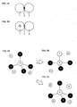
- a sulfide solid electrolyte material 1 and an electrode active material 2 react on an interface between both to form a high resistive layer X and increase interface resistance. It has been known as a means of solving this problem that a coating layer such as LiNbO 3 is provided for the surface of the electrode active material 2.
- the coating layer is provided for the surface of the electrode active material, it has been difficult to prevent a high resistive layer from being formed for the reason that it is difficult that the surface of the electrode active material is completely covered with the coating layer at a desired thinness, and adhesion properties between the electrode active material and the coating layer are so weak that the coating layer peels off easily due to shearing stress.
- the inventors of the present invention as shown in FIG. 1B , has confirmed that the introduction of fluorine (F) into the sulfide solid electrolyte material 1 may restrain interface resistance from increasing due to the formation of a high resistive layer. It is conceived that the reason why interface resistance may be restrained from increasing is that fluorine contained in the sulfide solid electrolyte material 1 and metal contained in the electrode active material 2 react to form stable fluoride Y on an interface between the sulfide solid electrolyte material 1 and the electrode active material 2. However, the problem is that the sulfide solid electrolyte material containing fluorine increases bulk resistance (decreases ion conductivity) even though it may restrain interface resistance from increasing.
- a sulfide solid electrolyte material of the first embodiment ordinarily reacts with an electrode active material to form a high resistive layer.
- the formation of a high resistive layer may be confirmed by a transmission electron microscope (TEM) and an energy-dispersive x-ray spectroscopy (EDX).
- TEM transmission electron microscope
- EDX energy-dispersive x-ray spectroscopy
- the above-mentioned sulfide solid electrolyte material has ion conductivity.
- a conducting metal ion is not particularly limited and examples thereof include Li ion, Na ion, K ion, Mg ion and Ca ion, and Li ion is preferable among them. The reason therefor is to allow a sulfide solid electrolyte material useful for a lithium solid state battery.
- composition of a sulfide solid electrolyte material of the first embodiment is not particularly limited if it is a composition containing at least one of Cl and Br.
- a sulfide solid electrolyte material of the first embodiment contains Li, X (X is P), and S in addition to at least one of Cl and Br. The reason therefor is to allow a sulfide solid electrolyte material with high Li ion conductivity.
- the above-mentioned sulfide solid electrolyte material preferably contains the PS 4 3- structure as the main body.
- the reason therefor is to allow a sulfide solid electrolyte material with less hydrogen sulfide generation amount.
- the phrase "contains the PS 4 3- structure as the main body" signifies that the ratio of the PS 4 3- structure in all anion structures is 50 mol% or more; the ratio of the PS 4 3- structure is preferably 60 mol% or more, more preferably 70 mol% or more., far more preferably 80 mol% or more, and particularly preferably 90 mol% or more.
- the above-mentioned sulfide solid electrolyte material preferably has only the PS 4 3- structure.
- the ratio of the PS 4 3- structure may be determined by Raman spectroscopy, NMR (for example, 31 P MAS NMR) and XPS.
- the above-mentioned sulfide solid electrolyte material preferably contains SiS 4 4- structure, GeS 4 4- structure, AlS 3 3- structure and BS 3 3- structure respectively as the main body.
- the definition of the main body and the measuring method for the ratio of each structure are the same as the contents described above.
- a sulfide solid electrolyte material of the first embodiment is preferably obtained by using a raw material composition containing Li 2 S, sulfide of X (X is P ), and at least one of a Cl-containing compound and a Br-containing compound.
- Li 2 S contained in a raw material composition preferably has fewer impurities. The reason therefor is to allow a side reaction to be restrained. Examples of a synthesis method for Li 2 S include a method described in Japanese Patent Application Publication No. H07-330312 . In addition, Li 2 S is preferably purified by using a method described in WO2005/040039 . On the other hand, examples of sulfide of the above-mentioned X contained in a raw material composition include P 2 S 3 , P 2 S 5 , SiS 2 , GeS 2 , Al 2 S 3 and B 2 S 3 .
- a Cl-containing compound contained in a raw material composition is not particularly limited if it contains chlorine, and examples thereof include LiCl.
- a Br-containing compound contained in a raw material composition is not particularly limited if it contains bromine, and examples thereof include LiBr.
- the sulfide solid electrolyte material does not contain Li 2 S.
- the reason therefor is to allow a sulfide solid electrolyte material with less hydrogen sulfide generation amount.
- Li 2 S reacts with water to generate hydrogen sulfide.
- a larger ratio of Li 2 S contained in a raw material composition survives Li 2 S more easily.
- the sulfide solid electrolyte material does not contain cross-linking sulfur.
- the reason therefor is to allow a sulfide solid electrolyte material with less hydrogen sulfide generation amount.
- cross-linking sulfur signifies cross-linking sulfur in a compound obtained by a reaction of Li 2 S and sulfide of the above-mentioned X.
- cross-linking sulfur with an S 3 P-S-PS 3 structure obtained by a reaction of Li 2 S and P 2 S 5 corresponds thereto.
- Such cross-linking sulfur reacts easily with water to easily generate hydrogen sulfide.
- the situation "does not contain cross-linking sulfur” may be confirmed by measuring Raman spectroscopy.
- the intensity I 402 at 402 cm -1 is preferably smaller than the intensity I 417 at 417 cm -1 . More specifically, the intensity I 402 is, for example, preferably 70% or less, more preferably 50% or less, and far more preferably 35% or less with respect to the intensity I 417 .
- the situation "does not contain cross-linking sulfur" may be determined by specifying a unit containing cross-linking sulfur to measure a peak of the unit.
- the sulfide solid electrolyte material does not contain Li 2 S and cross-linking sulfur
- the sulfide solid electrolyte material ordinarily has an ortho-composition or a composition in the neighborhood thereof.
- ortho generally signifies oxo acid which is the highest in degree of hydration among oxo acids obtained by hydrating the same oxide.
- a crystal composition to which Li 2 S is added most among sulfides is called an ortho-composition.
- Li 3 PS 4 corresponds to an ortho-composition in the Li 2 S-P 2 S 5 system
- Li 3 AlS 3 corresponds to an ortho-composition in the Li 2 S-Al 2 S 3 system
- Li 3 BS 3 corresponds to an ortho-composition in the Li 2 S-B 2 S 3 system
- Li 4 SiS 4 corresponds to an ortho-composition in the Li 2 S-SiS 2 system
- Li 4 GeS 4 corresponds to an ortho-composition in the Li 2 S-GeS 2 system.
- the case of an Li 2 S-Al 2 S 3 -based sulfide solid electrolyte material and the case of an Li 2 S-B 2 S 3 -based sulfide solid electrolyte material are similar thereto.
- Li 2 S-GeS 2 -based sulfide solid electrolyte material is similar thereto.
- the ratio of Li 2 S to the total of Li 2 S and P 2 S 5 is preferably within a range of 70 mol% to 80 mol%, more preferably within a range of 72 mol% to 78 mol%, and far more preferably within a range of 74 mol% to 76 mol%.
- the case where the above-mentioned raw material composition contains Li 2 S and Al 2 S 3 and the case where the above-mentioned raw material composition contains Li 2 S and B 2 S 3 are similar thereto.
- the ratio of Li 2 S to the total of Li 2 S and SiS 2 is preferably within a range of 62.5 mol% to 70.9 mol%, more preferably within a range of 63 mol% to 70 mol%, and far more preferably within a range of 64 mol% to 68 mol%.
- the case where the above-mentioned raw material composition contains Li 2 S and GeS 2 is similar thereto.
- the content of Cl in a sulfide solid electrolyte material of the first embodiment is not particularly limited and preferably within a range of 0.4 mol% to 50 mol% with respect to 1 mol of a sulfide solid electrolyte material before adding Cl thereto.
- the reason therefor is that too small content of Cl brings a possibility that interface resistance may not sufficiently be restrained from increasing, while too large content of Cl brings a possibility that Li ion conductivity of a sulfide solid electrolyte material decrease. It is conceived that Cl - is so small in polarizability as compared with S 2- that Li ion conductivity of a sulfide solid electrolyte material decreases.
- the polarizability of Cl - , Br - and I - is 2.96, 4.16 and 6.43 respectively, and the polarizability of S 2- is 5.90.
- the content of Br in a sulfide solid electrolyte material of the first embodiment is similar thereto.
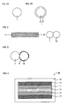
- Examples of an aspect of a sulfide solid electrolyte material of the first embodiment include a sulfide solid electrolyte material 1 (a dispersion-type sulfide solid electrolyte material) such that at least one of Cl and Br is dispersed, as shown in FIG. 3A .
- other examples of an aspect of the above-mentioned sulfide solid electrolyte material include a sulfide solid electrolyte material 1 (a covering-type sulfide solid electrolyte material) having a core portion 3 with ion conductivity and a covered portion 4 for covering the surface of the core portion 3 to contain at least one of Cl and Br, as shown in FIG. 3B .
- a dispersion-type sulfide solid electrolyte material has the advantage that the production is easy as compared with a covering-type sulfide solid electrolyte material.
- a covering-type sulfide solid electrolyte material has the advantage that interface resistance may be effectively restrained from increasing as compared with a dispersion-type sulfide solid electrolyte material.
- the covered portion may be formed on at least part of the core portion surface, the covered portion is preferably formed on more areas of the core portion surface, and the covered portion is more preferably formed on the whole core portion surface.
- the average thickness of the covered portion 4 is, for example, preferably within a range of 3 nm to 100 nm, and more preferably within a range of 3 nm to 20 nm.
- the above-mentioned covered portion include a covered portion composed of the above-mentioned Cl-containing compound or Br-containing compound, and a covered portion such that the above-mentioned core portion is chlorinated or brominated.
- the above-mentioned core portion may or may not have Cl and Br if it has ion conductivity.
- a dispersion-type sulfide solid electrolyte material may be used as the core portion; in the case of the latter, a conventional sulfide solid electrolyte material (such as Li 2 S-P 2 S 5 ) may be used as the core portion.
- a sulfide solid electrolyte material of the first embodiment may be amorphous or crystalline, and yet preferably amorphous.
- the core portion may be amorphous or crystalline, and yet preferably amorphous.
- An amorphous sulfide solid electrolyte material may be obtained by a mechanical milling method as described later.
- a crystalline sulfide solid electrolyte material may be obtained, for example, by heat-treating an amorphous sulfide solid electrolyte material.
- Examples of the shape of a sulfide solid electrolyte material of the first embodiment include a particulate.
- the average particle diameter of a particulate sulfide solid electrolyte material is, for example, preferably within a range of 0.1 ⁇ m to 50 ⁇ m.
- the above-mentioned sulfide solid electrolyte material is preferably high in Li ion conductivity, and Li ion conductivity at normal temperature is, for example, preferably 1 ⁇ 10 -4 S/cm or more, and more preferably 1 ⁇ 10 -3 S/cm or more.
- a sulfide solid electrolyte material of the first embodiment may be used for optional uses in which ion conductivity is required. Above all, the above-mentioned sulfide solid electrolyte material is preferably used for a battery. In addition, in the case where the above-mentioned sulfide solid electrolyte material is used for a battery, it may be used for a cathode active material layer (a cathode body), an anode active material layer (an anode body) or an electrolyte layer.
- the producing method for the sulfide solid electrolyte material of the first embodiment is not particularly limited if it is a method for obtaining the above-mentioned sulfide solid electrolyte material.
- Examples of the producing method for a dispersion-type sulfide solid electrolyte material include a producing method comprising a synthesis step of amorphizing a raw material composition containing Li 2 S, sulfide of X (X is P), and at least one of a Cl-containing compound and a Br-containing compound.
- Examples of a method for amorphizing include mechanical milling and melt extraction, and mechanical milling is preferable among them.
- the reason therefor is that treatment at normal temperature may be performed to intend the simplification of production processes.
- the mechanical milling is not particularly limited if it is a method for mixing a raw material composition while allowing mechanical energy thereto; examples thereof include ball mill, vibrating mill, turbo mill, mechano-fusion and disk mill, and ball mill is preferable among them and planetary ball mill is particularly preferable.
- the reason therefor is to efficiently obtain a desired sulfide solid electrolyte material.
- Various kinds of the conditions of the mechanical milling are determined so as to obtain a desired sulfide solid electrolyte material.
- a raw material composition and a grinding ball are added and treated at predetermined number of revolutions and time.
- larger number of revolutions brings higher production rate of a sulfide solid electrolyte material
- longer treating time brings higher conversion ratio of a raw material composition into a sulfide solid electrolyte material.
- the number of weighing table revolutions in performing planetary ball mill is preferably within a range of 200 rpm to 500 rpm, for example, and within a range of 250 rpm to 400 rpm, above all.
- the treating time in performing planetary ball mill is preferably within a range of 1 hour to 100 hours, for example, and within a range of 1 hour to 50 hours, above all.
- the above-mentioned mechanical milling may be dry-type mechanical milling or wet-type mechanical milling, but yet the latter is preferable.
- a raw material composition may be prevented from anchoring on a wall surface of a vessel to obtain a sulfide solid electrolyte material with higher amorphism.
- Liquid used for wet-type mechanical milling is preferably such as to have properties for not generating hydrogen sulfide in a reaction with the above-mentioned raw material composition. Hydrogen sulfide is generated in such a manner that a proton dissociated from a molecule of the liquid reacts with a raw material composition and a sulfide solid electrolyte material. Therefore, the above-mentioned liquid preferably has such aprotic properties as not to generate hydrogen sulfide. Ordinarily, aprotic liquid may be roughly divided into polar aprotic liquid and nonpolar aprotic liquid.
- the polar aprotic liquid is not particularly limited: Examples thereof include ketones such as acetone; nitriles such as acetonitrile; amides such as N,N-dimethylformamide (DMF); and sulfoxides such as dimethyl sulfoxide (DMSO).
- ketones such as acetone
- nitriles such as acetonitrile
- amides such as N,N-dimethylformamide (DMF)
- sulfoxides such as dimethyl sulfoxide (DMSO).
- nonpolar aprotic liquid examples include alkane which is liquid at normal temperature (25°C).
- the above-mentioned alkane may be chain alkane or cyclic alkane.
- the carbon number of the above-mentioned chain alkane is preferably 5 or more, for example.
- the upper limit of the carbon number of the above-mentioned chain alkane is not particularly limited if it is liquid at normal temperature.
- Specific examples of the above-mentioned chain alkane include pentane, hexane, heptane, octane, nonane, decane, undecane, dodecane and paraffin.
- the above-mentioned chain alkane may have a branch.
- Specific examples of the above-mentioned cyclic alkane include cyclopentane, cyclohexane, cycloheptane, cyclooctane and cycloparaffin.
- nonpolar aprotic liquid examples include aromatic hydrocarbons such as benzene, toluene and xylene; chain ethers such as diethyl ether and dimethyl ether; cyclic ethers such as tetrahydrofuran; alkyl halides such as chloroform, methyl chloride and methylene chloride; esters such as ethyl acetate; and fluorine-based compounds such as benzene fluoride, heptane fluoride, 2,3-dihydroperfluoropentane and 1,1,2,2,3,3,4-heptafluorocyclopentane.
- the added amount of the above-mentioned liquid is not particularly limited and may be such amount as to obtain a desired sulfide solid electrolyte material.
- a heat-treating step of heat-treating the sulfide solid electrolyte material obtained in the synthesis step may be performed in the above-mentioned producing method.
- the reason therefor is to obtain a crystalline sulfide solid electrolyte material.
- the heating temperature is preferably a temperature equal to or higher than crystallizing temperature.
- examples of the producing method for a covering-type sulfide solid electrolyte material include a producing method having a covering step of covering the surface of a sulfide solid electrolyte material as the core portion with at least one of a Cl-containing compound and a Br-containing compound.
- a covering-type sulfide solid electrolyte material may also be obtained in such a manner that Cl-containing gas (such as chlorine gas) or Br-containing gas (such as bromine gas) is jetted on the surface of a sulfide solid electrolyte material as the core portion to chlorinate or brominate the surface of the core portion.
- a sulfide solid electrolyte material of the second embodiment has a core portion with ion conductivity and a covered portion for covering the surface of the above-mentioned core portion, and is characterized in that the above-mentioned covered portion contains I.
- the second embodiment allows a sulfide solid electrolyte material which copes with both the restraint of the increase in interface resistance and the restraint of the increase in bulk resistance for the reason that the covered portion contains I.
- a sulfide solid electrolyte material containing iodine (I) is disclosed in the above-mentioned Non Patent Literatures 1 and 2.
- the covered portion for covering the core portion has iodine and iodine is effective for coping with both the restraint of the increase in interface resistance and the restraint of the increase in bulk resistance.
- a sulfide solid electrolyte material of the second embodiment has the core portion 3 with ion conductivity and the covered portion 4 for covering the surface of the core portion 3 to contain I, similarly to the sulfide solid electrolyte material 1 as shown in FIG. 3B .
- the core portion 3 may or may not have I if it has ion conductivity.
- a dispersion-type sulfide solid electrolyte material in which I is dispersed may be used as the core portion; in the case of the latter, a conventional sulfide solid electrolyte material (such as Li 2 S-P 2 S 5 ) may be used as the core portion.
- a dispersion-type sulfide solid electrolyte material in which I is dispersed is the same as the items described in the above-mentioned "1.
- First embodiment except for replacing Cl and Br with I.
- Examples of an I-containing compound include LiI.
- a covering-type sulfide solid electrolyte material is also the same as the items described in the above-mentioned "1.
- First embodiment except for replacing Cl and Br with I.
- a sulfide solid electrolyte material of the second embodiment may have the characteristics of a sulfide solid electrolyte material of the first embodiment.
- the cathode body of the present invention comprising a cathode active material and a sulfide solid electrolyte material which reacts with the above-mentioned cathode active material and forms a high resistive layer, characterized in that the above-mentioned sulfide solid electrolyte material contains at least one of Cl, Br and I.
- the present invention allows a cathode body which copes with both the restraint of the increase in interface resistance and the restraint of the increase in bulk resistance for the reason that a sulfide solid electrolyte material contains at least one of Cl, Br and I.
- FIG. 4 is a schematic view showing an example of a cathode body of the present invention.
- a cathode body 11 shown in FIG. 4 comprises a cathode active material 2a and a sulfide solid electrolyte material 1 which reacts with the cathode active material 2a and forms a high resistive layer (not shown in the drawing).
- a cathode body of the present invention is greatly characterized in that the sulfide solid electrolyte material 1 contains at least one of Cl, Br and I.
- a cathode body of the present invention is hereinafter described in each constitution.
- a sulfide solid electrolyte material in the present invention reacts with a cathode active material to form a high resistive layer.
- the formation of a high resistive layer may be confirmed by a transmission electron microscope (TEM) and an energy-dispersive x-ray spectroscopy (EDX).
- TEM transmission electron microscope
- EDX energy-dispersive x-ray spectroscopy
- a sulfide solid electrolyte material in the present invention may be a dispersion-type sulfide solid electrolyte material or a covering-type sulfide solid electrolyte material if it contains at least one of Cl, Br and I.
- the above-mentioned sulfide solid electrolyte material is the same as the contents described in the above-mentioned "A. Sulfide solid electrolyte material".
- A. Sulfide solid electrolyte material 2 the above-mentioned "A. Sulfide solid electrolyte material 2.
- Second embodiment describes a covering-type sulfide solid electrolyte material containing I and does not describe a dispersion-type sulfide solid electrolyte material containing I; a sulfide solid electrolyte material in the present invention may be a dispersion-type sulfide solid electrolyte material containing I.
- the reason therefor is as follows.
- Non Patent Literatures 1 and 2 A dispersion-type sulfide solid electrolyte material using LiI as a starting material is disclosed in Non Patent Literatures 1 and 2; LiI is so low in electric potential at which an oxidation reaction is caused (refer to paragraphs [0028] and [0029] of Patent Literature 2) as not to be used for a cathode body conventionally.
- the present invention adopts the constitution as described above by noting compatibility between the restraint of the increase in interface resistance and the restraint of the increase in bulk resistance to determine that the effect to be obtained is larger even though decomposition of LiI or the like is caused somewhat.
- a dispersion-type sulfide solid electrolyte material containing I even though LiI is used as a starting material, it is also conceived that I is dispersed so much that LiI is not decomposed at ordinary oxidation potential of LiI.
- a cathode active material preferably has the after-mentioned coating layer from the viewpoint of decreasing the influence of decomposition of LiI.
- the content of a sulfide solid electrolyte material in a cathode body is preferably, for example, within a range of 0.1% by volume to 80% by volume, above all, within a range of 1% by volume to 60% by volume, particularly, within a range of 10% by volume to 50% by volume.
- a cathode active material in the present invention is not particularly limited if it reacts with the above-mentioned sulfide solid electrolyte material to form a high resistive layer, and is preferably an oxide cathode active material, above all.
- a metallic element in an oxide cathode active material reacts with sulfur so more easily than oxygen as to react with sulfur in a sulfide solid electrolyte material and form sulfur metal. It is conceived that this sulfur metal itself becomes a high resistive layer while loss (decomposition) of metal ion and sulfur ion occurs in the vicinity of an interface between an oxide cathode active material and a sulfide solid electrolyte material.
- the use of an oxide cathode active material allows a cathode body with high energy density.
- M is preferably at least one kind selected from the group consisting of Co, Mn, Ni, V, Fe and Si, and more preferably at least one kind selected from the group consisting of Co, Ni and Mn.
- an oxide cathode active material examples include rock salt bed type active material such as LiCoO 2 , LiMnO 2 , LiNiO 2 , LiVO 2 and LiNi 1/3 Co 1/3 Mn 1/3 O 2 , and spinel type active material such as LiMn 2 O 4 and Li (Ni 0.5 Mn 1.5 ) O 4 .
- As an oxide cathode active material Li 2 FeSiO 4 , Li 2 MnSiO 4 or the like may be used, and olivine type active material such as LiFePO 4 , LiMnPO 4 , LiNiPO 4 , LiCuPO 4 or the like may be used.
- a cathode active material in the present invention is preferably an active material with an electric potential of 2.8 V (vs Li) or more.
- vs Li 2.8 V
- Patent Literature 2 it is described that LiI is subject to an oxidation reaction at an electric potential of approximately 3 V; according to the Nernst equation, an oxidation reaction occurs at 2.8 V.
- an active material with an electric potential of 2. 8 V (vs Li) or more and a sulfide solid electrolyte material using LiI as a starting material have not been combined conventionally.
- the electric potential of a cathode active material is preferably 3.0 V (vs Li) or more.
- a coating layer 5 of an oxide is preferably formed on the surface of the cathode active material 2a.
- the reason therefor is that a cathode active material and a sulfide solid electrolyte material may be further restrained from reacting to form a high resistive layer.
- the above-mentioned oxide is preferably an ion-conducting oxide.
- the reason therefor is that an ion conducts inside an ion-conducting oxide, so that resistance on the surface of a cathode active material may be decreased. Thus, a cathode body with low interface resistance may be obtained.
- an ion-conducting oxide preferably has Li element, M element (M is a metallic element) and O element.
- M is not particularly limited and examples thereof include Nb, Ti and Zr.
- specific examples of such an ion-conducting oxide include LiNbO 3 , Li 4 Ti 5 O 12 , LiTiO 3 and Li 2 ZrO 3 .
- the above-mentioned oxide may not have ion conductivity. In the case of using such an oxide, the formation of a high resistive layer may be restrained though initial properties of interface resistance may not be improved. Examples of an oxide having no ion conductivity include TiO 2 and ZrO 2 .
- the thickness of a coating layer is, for example, preferably within a range of 1 nm to 500 nm, and more preferably within a range of 2 nm to 100 nm. The reason therefor is that the thickness within the above-mentioned range may sufficiently restrain a cathode active material and a sulfide solid electrolyte material from reacting.
- Most of the surface of a cathode active material is preferably coated with a coating layer; specifically, the coverage factor is preferably 40% or more, more preferably 70% or more, and far more preferably 90% or more.
- Examples of a method for forming a coating layer on the surface of a cathode active material include a tumbling flow coating method (a sol-gel method), a mechano-fusion method, a CVD method and a PVD method.
- Examples of the shape of a cathode active material include a particulate shape, preferably a spherical shape or an elliptically spherical shape, above all.
- the average particle diameter thereof is, for example, preferably within a range of 0.1 ⁇ m to 50 ⁇ m.
- the content of a cathode active material in a cathode body is, for example, preferably within a range of 10% by volume to 99% by volume, more preferably within a range of 20% by volume to 99% by volume.
- a cathode body of the present invention may further comprise at least one of a conductive material and a binder in addition to a cathode active material and a sulfide solid electrolyte material.
- the conductive material include acetylene black, Ketjen Black and carbon fiber.
- the binder include fluorine-containing binders such as PTFE and PVDF.
- the thickness of the above-mentioned cathode body is, for example, preferably within a range of 0.1 ⁇ m to 1000 ⁇ m.
- Examples of a method for forming a cathode body include a method for compression-molding a material composing a cathode body.
- the above-mentioned cathode body is ordinarily used for a battery and preferably used for a solid state battery, above all.
- the lithium solid state battery of the present invention comprises a cathode active material layer, an anode active material layer, and a solid electrolyte layer formed between the above-mentioned cathode active material layer and the above-mentioned anode active material layer, characterized in that the above-mentioned cathode active material layer is the above-mentioned cathode body.
- the present invention allows a lithium solid state battery which copes with both the restraint of the increase in interface resistance and the restraint of the increase in bulk resistance by reason of using the above-mentioned cathode body as a cathode active material layer.
- FIG. 6 is a schematic cross-sectional view showing an example of a lithium solid state battery of the present invention.
- a lithium solid state battery 20 shown in FIG. 6 comprises: a cathode active material layer 11 containing a cathode active material, an anode active material layer 12 containing an anode active material, a solid electrolyte layer 13 formed between the cathode active material layer 11 and the anode active material layer 12, a cathode current collector 14 for collecting the cathode active material layer 11, an anode current collector 15 for collecting the anode active material layer 12, and a battery case 16 for storing these members.
- the present invention is greatly characterized in that the cathode body described in the above-mentioned "B. cathode body" is used for the cathode active material layer 11.
- a lithium solid state battery of the present invention is hereinafter described in each constitution.
- a cathode active material layer in the present invention is the same as the contents described in the above-mentioned "B. cathode body"; therefore, the description will not be repeated here.
- the anode active material layer in the present invention is a layer containing at least an anode active material, and may further contain at least one of a solid electrolyte material, a conductive material and a binder as required.
- a solid electrolyte material contained in the anode active material layer is preferably the sulfide solid electrolyte material described in.the above-mentioned "A. Sulfide solid electrolyte material".
- the content of the above-mentioned sulfide solid electrolyte material in the anode active material layer is preferably, for example, within a range of 0.1% by volume to 80% by volume, above all, within a range of 1% by volume to 60% by volume, and particularly, within a range of 10% by volume to 50% by volume.
- Examples of the anode active material include a metal active material and a carbon active material.
- Examples of the metal active material include In, Al, Si, and Sn.
- examples of the carbon active material include mesocarbon microbeads (MCMB), high orientation property graphite (HOPG), hard carbon and soft carbon.
- the content of the anode active material in the anode active material layer is, for example, preferably within a range of 10% by volume to 99% by volume, and more preferably within a range of 20% by volume to 99% by volume.
- the conductive material examples include acetylene black, Ketjen Black and carbon fiber.
- the binder examples include fluorine-containing binders such as PTFE and PVDF.
- the thickness of the anode active material layer is preferably within a range of 0.1 ⁇ m to 1000 ⁇ m, for example.
- the solid electrolyte layer in the present invention is a layer formed between the cathode active material layer and the anode active material layer, and a layer composed of a solid electrolyte material.
- the solid electrolyte material contained in the solid electrolyte layer is not particularly limited if it has Li ion conductivity.
- a solid electrolyte material contained in the solid electrolyte layer is preferably the sulfide solid electrolyte material described in the above-mentioned "A. Sulfide solid electrolyte material".
- the reason therefor is that the formation of a high resistive layer may be prevented on an interface with the cathode active material layer.
- the content of the above-mentioned sulfide solid electrolyte material in the solid electrolyte layer is not particularly limited if it is a ratio for obtaining desired insulation properties, and is preferably within a range of 10% by volume to 100% by volume, for example, and within a range of 50% by volume to 100% by volume, above all.
- the solid electrolyte layer is preferably composed of only the above-mentioned sulfide solid electrolyte material.
- the solid electrolyte layer may contain a binder.
- the reason therefor is that the solid electrolyte layer with flexibility may be obtained by containing a binder.
- the binder include fluorine-containing binders such as PTFE and PVDF.
- the thickness of the solid electrolyte layer is preferably within a range of 0.1 ⁇ m to 1000 ⁇ m, for example, and within a range of 0.1 ⁇ m to 300 ⁇ m, above all.
- a lithium solid state battery of the present invention comprises at least the above-mentioned cathode active material layer, anode active material layer and solid electrolyte layer, and moreover, ordinarily further comprises a cathode current collector for collecting the cathode active material layer and an anode current collector for collecting the anode active material layer.
- a material for the cathode current collector include SUS, aluminum, nickel, iron, titanium and carbon, while preferably SUS among them.
- examples of a material for the anode current collector include SUS, copper, nickel and carbon, while preferably SUS among them.
- the thickness and shape of the cathode current collector and the anode current collector are preferably selected properly in accordance with uses of a lithium solid state battery.
- a battery case of a general lithium solid state battery may be used for a battery case used for the present invention. Examples of the battery case include a battery case made of SUS.
- a lithium solid state battery of the present invention may be a primary battery or a secondary battery, however preferably a secondary battery among them.
- the reason therefor is to be repeatedly charged and discharged and be useful as a car-mounted battery, for example.
- Examples of the shape of a lithium solid state battery of the present invention include a coin shape, a laminate shape, a cylindrical shape and a rectangular shape.
- a producing method for a lithium solid state battery of the present invention is not particularly limited if it is a method for obtaining the above-mentioned lithium solid state battery, and the same method as a producing method for a general lithium solid state battery may be used.
- Examples of a producing method for a lithium solid state battery include a method such that a material composing a cathode active material layer, a material composing a solid electrolyte layer and a material composing an anode active material layer are sequentially pressed to thereby produce a power generating element and this power generating element is stored inside a battery case, which is swaged.
- the present invention may also provide each of an anode active material layer (an anode body) and a solid electrolyte layer, characterized by containing the sulfide solid electrolyte material described in the above-mentioned "A. Sulfide solid electrolyte material”.
- the present invention is not limited to the above-mentioned embodiments.
- the above-mentioned embodiments are exemplification, and any is included in the technical scope of the present invention if it has substantially the same constitution as the technical idea described in the claim of the present invention and offers similar operation and effect thereto.
- Li 2 S Lithium sulfide
- P 2 S 5 diphosphorus pentasulfide
- LiCl lithium chloride
- a lithium solid state battery was obtained by using the obtained cathode composite, anode composite and the 75Li 2 S ⁇ 25P 2 S 5 amorphous substance prepared as a solid electrolyte layer-forming material.
- a lithium solid state battery was obtained in the same manner as Example 1 except for replacing LiCl with LiI.
- a lithium solid state battery was obtained in the same manner as Example 2 except for replacing LiCl with LiI.
- a lithium solid state battery was obtained in the same manner as Example 1 except for not using LiCl.
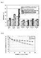
- Impedance measurement was performed by using the lithium solid state battery obtained in Examples 1 to 4 and Comparative Examples 1 to 3. First, the lithium solid state battery was charged. The charging conditions were the conditions of charging up to 3.7 V by CCCV. After charging, interface resistance (initial) and bulk resistance (initial) were measured by impedance measurement with an alternating current impedance method. Solartron 1260TM was used for the measurement and the measurement conditions were a voltage amplitude of ⁇ 10 mV, a measuring frequency of 1 MHz to 0.1 Hz, and 25°C. Thereafter, the lithium solid state battery after the above-mentioned impedance measurement was preserved under an environment of 60°C for 20 days.
- the charging conditions were the conditions of charging up to 3.7 V by CCCV. After charging, interface resistance (initial) and bulk resistance (initial) were measured by impedance measurement with an alternating current impedance method. Solartron 1260TM was used for the measurement and the measurement conditions were a voltage amplitude of ⁇ 10 mV,
- the lithium solid state battery was placed under an environment of 25°C for 2 hours to subsequently measure interface resistance (after high-temperature preservation) and bulk resistance (after high-temperature preservation) by impedance measurement on the same conditions as the above. The results are shown in FIG. 7 and TABLE 1.
- Li ion conductivity of the sulfide solid electrolyte materials synthesized in Comparative Examples 1 to 3 was measured by an alternating current impedance method. Solartron 1260TM was used for the measurement and the measurement conditions were a voltage amplitude of ⁇ 5 mV, a measuring frequency of 1 MHz to 0.1 Hz, and 25°C. The results are shown in FIG. 9 . As shown in FIG. 9 , it was confirmed that Li ion conductivity deteriorated as fluorine added amount increased.
- Structural stability was calculated for a structure such that S of Li 3 PS 4 was substituted with F by a molecular orbital method (Gaussian03: Mp2/6-311G(d,p)). Specifically, structural stability was calculated for Li 3 PS 3 F, Li 2 PS 3 F, Li 2 PS 2 F 2 , LiPS 2 F 2 , LiPSF 3 and PSF 3 . As a result, it was found that Li 3 PS 3 F might exist stably and it was suggested that a PS 4 3- structure was destroyed by F.
- Structural stability was calculated for a structure such that S of Li 3 PS 4 was substituted with each of Cl, Br and I by a molecular orbital method (Gaussian03: Mp2/6-3111G(d,p)).
- the targeted substitution structure is the same as Reference Example 1. As a result, it was found that any structure might not exist stably and it was suggested that a PS4 3- structure was not destroyed by Cl, Br and I.
Description
- The present invention relates to a sulfide solid electrolyte material which copes with both the restraint of the increase in interface resistance and the restraint of the increase in bulk resistance.
- In accordance with a rapid spread of information relevant apparatuses and communication apparatuses such as a personal computer, a video camera and a portable telephone in recent years, the development of a battery to be utilized as a power source thereof has been emphasized. The development of a high-output and high-capacity battery for an electric automobile or a hybrid automobile has been advanced also in the industrial field such as the automobile industry. A lithium battery has been presently noticed from the viewpoint of a high energy density among various kinds of batteries.
- Liquid electrolyte containing a flammable organic solvent is used for a presently commercialized lithium battery, so that the installation of a safety device for restraining temperature rise during a short circuit and the improvement in structure and material for preventing the short circuit are necessary therefor. On the contrary, a lithium battery all-solidified by replacing the liquid electrolyte with a solid electrolyte layer is conceived to intend the simplification of the safety device and be excellent in production cost and productivity for the reason that the flammable organic solvent is not used in the battery. In addition, a sulfide solid electrolyte material has been known as a solid electrolyte material used for such a solid electrolyte layer.
- The sulfide solid electrolyte material is so high in Li ion conductivity as to be useful for intending higher output of a battery, and various kinds of research have been conventionally made. For example, in
Patent Literature 1, Li2S-P2S5-based lithium ion conductor crystal glass and a battery using this as a solid electrolyte are disclosed. Also, inNon Patent Literature 1, a sulfide solid electrolyte material with a ratio of Li2S/P2S5 = 2, containing LiI, is disclosed. In addition, inNon Patent Literature 2, an LiI-Li2S-P2S5-based amorphous material obtained by a mechanical milling method is disclosed. Also, inPatent Literature 2, in order to restrain a reaction of a cathode active material and a solid electrolyte, a nonaqueous electrolyte battery selecting a combination of the solid electrolytes for a specific combination is disclosed. -
- Patent Literature 1: Japanese Patent Application Publication No.
2005-228570 - Patent Literature 2: Japanese Patent Application Publication No.
2003-217663 -
- Non Patent Literature 1: Rene Mercier et al., "SUPERIONIC CONDUCTION IN Li2S-P2S5-LiI-GLASSES", Solid State Ionics 5 (1981), 663-666
- Non Patent Literature 2: Naoko Tomei, two others, "Preparation of Amorphous Materials in the system LiI-Li2S-P2S5 by Mechanical Milling and Their Lithium Ion Conducting Properties", Summary of Solid State Ionics Symposium, Vol. 23 (2003), P. 26-27
- The problem is that a sulfide solid electrolyte material reacts with an electrode active material (particularly, a cathode active material) to form a high resistive layer on an interface between both and increase interface resistance. On the contrary, the inventors of the present invention obtain knowledge that the inclusion of fluorine in a sulfide solid electrolyte material restrains the increase in interface resistance. However, the problem is that a sulfide solid electrolyte material containing fluorine increases bulk resistance (decreases ion conductivity) even though it may restrain interface resistance from increasing. The present invention has been made in view of the above-mentioned problems, and the main object thereof is to provide a sulfide solid electrolyte material which copes with both the restraint of the increase in interface resistance and the restraint of the increase in bulk resistance.
- To solve the above-mentioned problems, the present invention provides a sulfide solid electrolyte material according to
claim 1. The sulfide solid electrolyte material contains at least one of Cl and Br. - The present invention allows a sulfide solid electrolyte material which copes with both the restraint of the increase in interface resistance and the restraint of the increase in bulk resistance by reason of containing at least one of Cl and Br.
- In the above-mentioned invention, at least one of the Cl and Br is preferably dispersed. The reason therefor is that a sulfide solid electrolyte material is easily produced.
- In the above-mentioned invention, the sulfide solid electrolyte material preferably comprises a core portion with ion conductivity and a covered portion for covering a surface of the core portion; wherein the covered portion contains at least one of the Cl and Br. The reason therefor is that interface resistance may be effectively restrained from increasing.
- Furthermore, it is disclosed herewith a sulfide solid electrolyte material comprising a core portion with ion conductivity and a covered portion for covering a surface of the core portion; characterized in that the covered portion contains I.
- The present invention allows a sulfide solid electrolyte material which copes with both the restraint of the increase in interface resistance and the restraint of the increase in bulk resistance for the reason that a covered portion contains I.
- In the above-mentioned invention, the sulfide solid electrolyte material comprises Li, P and S. The reason therefor is to allow a sulfide solid electrolyte material with high Li ion conductivity.
- In the above-mentioned invention, the sulfide solid electrolyte material contains a PS4 3- structure as a main body. The reason therefor is to allow a sulfide solid electrolyte material with less hydrogen sulfide generation amount.
- Furthermore, the present invention provides a cathode body according to
claim 2. The cathode body comprises a cathode active material and a sulfide solid electrolyte material which reacts with the cathode active material and forms a high resistive layer; characterized in that the sulfide solid electrolyte material contains at least one of Cl and Br. - The present invention allows a cathode body which copes with both the restraint of the increase in interface resistance and the restraint of the increase in bulk resistance for the reason that a sulfide solid electrolyte material contains at least one of Cl and Br.
- In the above-mentioned invention, the cathode active material is preferably an oxide cathode active material. The reason therefor is to react with a sulfide solid electrolyte material to easily form a high resistive layer. An oxide cathode active material also has the advantage that energy density is high.
- In the above-mentioned invention, the oxide cathode active material is preferably a rock salt bed type active material.
- In the above-mentioned invention, a coating layer of an oxide is preferably formed on a surface of the cathode active material. The reason therefor is that a cathode active material and a sulfide solid electrolyte material may be further restrained from reacting to form a high resistive layer.
- In the above-mentioned invention, the sulfide solid electrolyte material comprises Li, P and S. The reason therefor is to allow a sulfide solid electrolyte material with high Li ion conductivity.
- In the above-mentioned invention, the sulfide solid electrolyte material contains a PS4 3- structure as a main body. The reason therefor is to allow a sulfide solid electrolyte material with less hydrogen sulfide generation amount.
- Furthermore, the present invention provides a lithium solid state battery according to
claim 5. The battery comprises a cathode active material layer, an anode active material layer, and a solid electrolyte layer formed between the cathode active material layer and the anode active material layer; characterized in that the cathode active material layer is the cathode body. - The present invention allows a lithium solid state battery which copes with both the restraint of the increase in interface resistance and the restraint of the increase in bulk resistance by reason of using the above-mentioned cathode body as a cathode active material layer.
- The present invention produces the effect such as to allow a sulfide solid electrolyte material which copes with both the restraint of the increase in interface resistance and the restraint of the increase in bulk resistance.
-
-
FIGS. 1A and 1B are each a schematic cross-sectional view explaining an interface between a sulfide solid electrolyte material and an electrode active material. -
FIGS. 2A to 2C are schematic views explaining an effect of the present invention. -
FIGS. 3A and 3B are each a schematic cross-sectional view showing a sulfide solid electrolyte material of the present invention. -
FIG. 4 is a schematic view showing an example of a cathode body of the present invention. -
FIG. 5 is a schematic cross-sectional view explaining a cathode body of the present invention. -
FIG. 6 is a schematic cross-sectional view showing an example of a lithium solid state battery of the present invention. -
FIG. 7 is a result of measuring impedance for a lithium solid state battery obtained in Examples 1 to 4 and Comparative Examples 1 to 3. -
FIG. 8 is a result of evaluating charge-discharge cycle characteristics for a lithium solid state battery obtained in Example 5 and Comparative Example 1. -
FIG. 9 is a result of measuring Li ion conductivity for a sulfide solid electrolyte material synthesized in Comparative Examples 1 to 3. - A sulfide solid electrolyte material, a cathode body and a lithium solid state battery of the present invention are hereinafter described in detail.
- A sulfide solid electrolyte material of the present invention is first described. A sulfide solid electrolyte material of the present invention may be roughly divided into two embodiments. A sulfide solid electrolyte material of the present invention is hereinafter described while divided into a first embodiment and a second embodiment.
- A sulfide solid electrolyte material of a first embodiment is characterized by containing at least one of Cl and Br.
- The first embodiment allows a sulfide solid electrolyte material which copes with both the restraint of the increase in interface resistance and the restraint of the increase in bulk resistance by reason of containing at least one of Cl and Br. Here, as shown in
FIG. 1A , conventionally, the problem is that a sulfidesolid electrolyte material 1 and an electrodeactive material 2 react on an interface between both to form a high resistive layer X and increase interface resistance. It has been known as a means of solving this problem that a coating layer such as LiNbO3 is provided for the surface of the electrodeactive material 2. However, even though the coating layer is provided for the surface of the electrode active material, it has been difficult to prevent a high resistive layer from being formed for the reason that it is difficult that the surface of the electrode active material is completely covered with the coating layer at a desired thinness, and adhesion properties between the electrode active material and the coating layer are so weak that the coating layer peels off easily due to shearing stress. - On the contrary, the inventors of the present invention, as shown in
FIG. 1B , has confirmed that the introduction of fluorine (F) into the sulfidesolid electrolyte material 1 may restrain interface resistance from increasing due to the formation of a high resistive layer. It is conceived that the reason why interface resistance may be restrained from increasing is that fluorine contained in the sulfidesolid electrolyte material 1 and metal contained in the electrodeactive material 2 react to form stable fluoride Y on an interface between the sulfidesolid electrolyte material 1 and the electrodeactive material 2. However, the problem is that the sulfide solid electrolyte material containing fluorine increases bulk resistance (decreases ion conductivity) even though it may restrain interface resistance from increasing. - It is probably conceived that the reason why bulk resistance increases is that the introduction of fluorine with large electronegativity and high reactivity substitutes sulfur (S) of a structural unit (a unit) in charge of ionic conduction with fluorine (F) to inhibit ionic conduction. For example, as shown in
FIG. 2A , a sulfide solid electrolyte material (Li3PS4) having a composition of 75Li2S · 25P2S5 has a PS4 3- structure, which contributes greatly to Li ionic conduction. It is conceived that the introduction of fluorine into such a sulfide solid electrolyte material, as shown inFIG. 2B , substitutes sulfur (S) of the PS4 3- structure with fluorine (F) · to inhibit Li ionic conduction. On the contrary, in the first embodiment, as shown inFIG. 2C , the introduction of chlorine or bromine with lower reactivity than fluorine, which is the same halogen as fluorine, causes no above-mentioned substitution. As a result, a sulfide solid electrolyte material which copes with both the restraint of the increase in interface resistance and the restraint of the increase in bulk resistance is allowed. - A sulfide solid electrolyte material of the first embodiment ordinarily reacts with an electrode active material to form a high resistive layer. The formation of a high resistive layer may be confirmed by a transmission electron microscope (TEM) and an energy-dispersive x-ray spectroscopy (EDX). The above-mentioned sulfide solid electrolyte material has ion conductivity. A conducting metal ion is not particularly limited and examples thereof include Li ion, Na ion, K ion, Mg ion and Ca ion, and Li ion is preferable among them. The reason therefor is to allow a sulfide solid electrolyte material useful for a lithium solid state battery.
- The composition of a sulfide solid electrolyte material of the first embodiment is not particularly limited if it is a composition containing at least one of Cl and Br. Above all, a sulfide solid electrolyte material of the first embodiment contains Li, X (X is P), and S in addition to at least one of Cl and Br. The reason therefor is to allow a sulfide solid electrolyte material with high Li ion conductivity.
- In the case where the above-mentioned X is P, the above-mentioned sulfide solid electrolyte material preferably contains the PS4 3- structure as the main body. The reason therefor is to allow a sulfide solid electrolyte material with less hydrogen sulfide generation amount. The phrase "contains the PS4 3- structure as the main body" signifies that the ratio of the PS4 3- structure in all anion structures is 50 mol% or more; the ratio of the PS4 3- structure is preferably 60 mol% or more, more preferably 70 mol% or more., far more preferably 80 mol% or more, and particularly preferably 90 mol% or more. In particular, the above-mentioned sulfide solid electrolyte material preferably has only the PS4 3- structure. The ratio of the PS4 3- structure may be determined by Raman spectroscopy, NMR (for example, 31P MAS NMR) and XPS.
- In the case where the above-mentioned X is Si, Ge, A1 or B, which is not according to the invention, the above-mentioned sulfide solid electrolyte material preferably contains SiS4 4- structure, GeS4 4- structure, AlS3 3- structure and BS3 3- structure respectively as the main body. The definition of the main body and the measuring method for the ratio of each structure are the same as the contents described above.
- Also, a sulfide solid electrolyte material of the first embodiment is preferably obtained by using a raw material composition containing Li2S, sulfide of X (X is P ), and at least one of a Cl-containing compound and a Br-containing compound.
- Li2S contained in a raw material composition preferably has fewer impurities. The reason therefor is to allow a side reaction to be restrained. Examples of a synthesis method for Li2S include a method described in Japanese Patent Application Publication No.
H07-330312 WO2005/040039 . On the other hand, examples of sulfide of the above-mentioned X contained in a raw material composition include P2S3, P2S5, SiS2, GeS2, Al2S3 and B2S3. - A Cl-containing compound contained in a raw material composition is not particularly limited if it contains chlorine, and examples thereof include LiCl. A Br-containing compound contained in a raw material composition is not particularly limited if it contains bromine, and examples thereof include LiBr.
- According to the invention the sulfide solid electrolyte material does not contain Li2S. The reason therefor is to allow a sulfide solid electrolyte material with less hydrogen sulfide generation amount. Li2S reacts with water to generate hydrogen sulfide. For example, a larger ratio of Li2S contained in a raw material composition survives Li2S more easily. The situation "does not contain Li2S" may be confirmed by X-ray diffraction. Specifically, in the case of not having a peak of Li2S (2θ = 27.0°, 31.2°, 44.8° and 53.1°), "does not substantially contain Li2S" may be determined.
- According to the invention the sulfide solid electrolyte material does not contain cross-linking sulfur. The reason therefor is to allow a sulfide solid electrolyte material with less hydrogen sulfide generation amount. The term "cross-linking sulfur" signifies cross-linking sulfur in a compound obtained by a reaction of Li2S and sulfide of the above-mentioned X. For example, cross-linking sulfur with an S3P-S-PS3 structure obtained by a reaction of Li2S and P2S5 corresponds thereto. Such cross-linking sulfur reacts easily with water to easily generate hydrogen sulfide. In addition, the situation "does not contain cross-linking sulfur" may be confirmed by measuring Raman spectroscopy. For example, in the case of an Li2S-P2S5-based sulfide solid electrolyte material, a peak of an S3P-S-PS3 structure ordinarily appears at 402 cm-1. Thus, it is preferable that this peak is not detected. A peak of a PS4 3- structure ordinarily appears at 417 cm-1. In the first embodiment, the intensity I402 at 402 cm-1 is preferably smaller than the intensity I417 at 417 cm-1. More specifically, the intensity I402 is, for example, preferably 70% or less, more preferably 50% or less, and far more preferably 35% or less with respect to the intensity I417. Also, with regard to a sulfide solid electrolyte material except Li2S-P2S5-based, the situation "does not contain cross-linking sulfur" may be determined by specifying a unit containing cross-linking sulfur to measure a peak of the unit.
- In the case where the above-mentioned sulfide solid electrolyte material does not contain Li2S and cross-linking sulfur, the sulfide solid electrolyte material ordinarily has an ortho-composition or a composition in the neighborhood thereof. Here, ortho generally signifies oxo acid which is the highest in degree of hydration among oxo acids obtained by hydrating the same oxide. In the first embodiment, a crystal composition to which Li2S is added most among sulfides is called an ortho-composition. For example, Li3PS4 corresponds to an ortho-composition in the Li2S-P2S5 system, Li3AlS3 corresponds to an ortho-composition in the Li2S-Al2S3 system, Li3BS3 corresponds to an ortho-composition in the Li2S-B2S3 system, Li4SiS4 corresponds to an ortho-composition in the Li2S-SiS2 system, and Li4GeS4 corresponds to an ortho-composition in the Li2S-GeS2 system.
- For example, in the case of an Li2S-P2S5-based sulfide solid electrolyte material, the ratio of Li2S and P2S5 for obtaining an ortho-composition is Li2S : P2S5 = 75 : 25 on a molar basis. The case of an Li2S-Al2S3-based sulfide solid electrolyte material and the case of an Li2S-B2S3-based sulfide solid electrolyte material are similar thereto. On the other hand, in the case of an Li2S-SiS2-based sulfide solid electrolyte material, the ratio of Li2S and SiS2 for obtaining an ortho-composition is Li2S : SiS2 = 66.7 : 33.3 on a molar basis. The case of an Li2S-GeS2-based sulfide solid electrolyte material is similar thereto.
- In the case where the above-mentioned raw material composition contains Li2S and P2S5, the ratio of Li2S to the total of Li2S and P2S5 is preferably within a range of 70 mol% to 80 mol%, more preferably within a range of 72 mol% to 78 mol%, and far more preferably within a range of 74 mol% to 76 mol%. The case where the above-mentioned raw material composition contains Li2S and Al2S3 and the case where the above-mentioned raw material composition contains Li2S and B2S3 are similar thereto.
- On the other hand, in the case where the above-mentioned raw material composition contains Li2S and SiS2, the ratio of Li2S to the total of Li2S and SiS2 is preferably within a range of 62.5 mol% to 70.9 mol%, more preferably within a range of 63 mol% to 70 mol%, and far more preferably within a range of 64 mol% to 68 mol%. The case where the above-mentioned raw material composition contains Li2S and GeS2 is similar thereto.
- The content of Cl in a sulfide solid electrolyte material of the first embodiment is not particularly limited and preferably within a range of 0.4 mol% to 50 mol% with respect to 1 mol of a sulfide solid electrolyte material before adding Cl thereto. The reason therefor is that too small content of Cl brings a possibility that interface resistance may not sufficiently be restrained from increasing, while too large content of Cl brings a possibility that Li ion conductivity of a sulfide solid electrolyte material decrease. It is conceived that Cl- is so small in polarizability as compared with S2- that Li ion conductivity of a sulfide solid electrolyte material decreases. The polarizability of Cl-, Br- and I- is 2.96, 4.16 and 6.43 respectively, and the polarizability of S2- is 5.90. The content of Br in a sulfide solid electrolyte material of the first embodiment is similar thereto.
- Examples of an aspect of a sulfide solid electrolyte material of the first embodiment include a sulfide solid electrolyte material 1 (a dispersion-type sulfide solid electrolyte material) such that at least one of Cl and Br is dispersed, as shown in
FIG. 3A . On the other hand, other examples of an aspect of the above-mentioned sulfide solid electrolyte material include a sulfide solid electrolyte material 1 (a covering-type sulfide solid electrolyte material) having acore portion 3 with ion conductivity and a coveredportion 4 for covering the surface of thecore portion 3 to contain at least one of Cl and Br, as shown inFIG. 3B . A dispersion-type sulfide solid electrolyte material has the advantage that the production is easy as compared with a covering-type sulfide solid electrolyte material. On the other hand, a covering-type sulfide solid electrolyte material has the advantage that interface resistance may be effectively restrained from increasing as compared with a dispersion-type sulfide solid electrolyte material. - With regard to a covering-type sulfide solid electrolyte material, the covered portion may be formed on at least part of the core portion surface, the covered portion is preferably formed on more areas of the core portion surface, and the covered portion is more preferably formed on the whole core portion surface. In
FIG. 3B , the average thickness of the coveredportion 4 is, for example, preferably within a range of 3 nm to 100 nm, and more preferably within a range of 3 nm to 20 nm. Examples of the above-mentioned covered portion include a covered portion composed of the above-mentioned Cl-containing compound or Br-containing compound, and a covered portion such that the above-mentioned core portion is chlorinated or brominated. The above-mentioned core portion may or may not have Cl and Br if it has ion conductivity. In the case of the former, a dispersion-type sulfide solid electrolyte material may be used as the core portion; in the case of the latter, a conventional sulfide solid electrolyte material (such as Li2S-P2S5) may be used as the core portion. - A sulfide solid electrolyte material of the first embodiment may be amorphous or crystalline, and yet preferably amorphous. In the case where the above-mentioned sulfide solid electrolyte material has the core portion and the covered portion, the core portion may be amorphous or crystalline, and yet preferably amorphous. An amorphous sulfide solid electrolyte material may be obtained by a mechanical milling method as described later. On the other hand, a crystalline sulfide solid electrolyte material may be obtained, for example, by heat-treating an amorphous sulfide solid electrolyte material.
- Examples of the shape of a sulfide solid electrolyte material of the first embodiment include a particulate. The average particle diameter of a particulate sulfide solid electrolyte material is, for example, preferably within a range of 0.1 µm to 50 µm. The above-mentioned sulfide solid electrolyte material is preferably high in Li ion conductivity, and Li ion conductivity at normal temperature is, for example, preferably 1 × 10⁻⁴ S/cm or more, and more preferably 1 × 10⁻³ S/cm or more.
- A sulfide solid electrolyte material of the first embodiment may be used for optional uses in which ion conductivity is required. Above all, the above-mentioned sulfide solid electrolyte material is preferably used for a battery. In addition, in the case where the above-mentioned sulfide solid electrolyte material is used for a battery, it may be used for a cathode active material layer (a cathode body), an anode active material layer (an anode body) or an electrolyte layer.
- Next, a producing method for a sulfide solid electrolyte material of the first embodiment is described. The producing method for the sulfide solid electrolyte material of the first embodiment is not particularly limited if it is a method for obtaining the above-mentioned sulfide solid electrolyte material. Examples of the producing method for a dispersion-type sulfide solid electrolyte material include a producing method comprising a synthesis step of amorphizing a raw material composition containing Li2S, sulfide of X (X is P), and at least one of a Cl-containing compound and a Br-containing compound.
- Examples of a method for amorphizing include mechanical milling and melt extraction, and mechanical milling is preferable among them. The reason therefor is that treatment at normal temperature may be performed to intend the simplification of production processes.
- The mechanical milling is not particularly limited if it is a method for mixing a raw material composition while allowing mechanical energy thereto; examples thereof include ball mill, vibrating mill, turbo mill, mechano-fusion and disk mill, and ball mill is preferable among them and planetary ball mill is particularly preferable. The reason therefor is to efficiently obtain a desired sulfide solid electrolyte material.
- Various kinds of the conditions of the mechanical milling are determined so as to obtain a desired sulfide solid electrolyte material. For example, in the case of using planetary ball mill, a raw material composition and a grinding ball are added and treated at predetermined number of revolutions and time. Generally, larger number of revolutions brings higher production rate of a sulfide solid electrolyte material, and longer treating time brings higher conversion ratio of a raw material composition into a sulfide solid electrolyte material. The number of weighing table revolutions in performing planetary ball mill is preferably within a range of 200 rpm to 500 rpm, for example, and within a range of 250 rpm to 400 rpm, above all. The treating time in performing planetary ball mill is preferably within a range of 1 hour to 100 hours, for example, and within a range of 1 hour to 50 hours, above all.
- The above-mentioned mechanical milling may be dry-type mechanical milling or wet-type mechanical milling, but yet the latter is preferable. The reason therefor is that a raw material composition may be prevented from anchoring on a wall surface of a vessel to obtain a sulfide solid electrolyte material with higher amorphism. Liquid used for wet-type mechanical milling is preferably such as to have properties for not generating hydrogen sulfide in a reaction with the above-mentioned raw material composition. Hydrogen sulfide is generated in such a manner that a proton dissociated from a molecule of the liquid reacts with a raw material composition and a sulfide solid electrolyte material. Therefore, the above-mentioned liquid preferably has such aprotic properties as not to generate hydrogen sulfide. Ordinarily, aprotic liquid may be roughly divided into polar aprotic liquid and nonpolar aprotic liquid.
- The polar aprotic liquid is not particularly limited: Examples thereof include ketones such as acetone; nitriles such as acetonitrile; amides such as N,N-dimethylformamide (DMF); and sulfoxides such as dimethyl sulfoxide (DMSO).
- Examples of the nonpolar aprotic liquid include alkane which is liquid at normal temperature (25°C). The above-mentioned alkane may be chain alkane or cyclic alkane. The carbon number of the above-mentioned chain alkane is preferably 5 or more, for example. On the other hand, the upper limit of the carbon number of the above-mentioned chain alkane is not particularly limited if it is liquid at normal temperature. Specific examples of the above-mentioned chain alkane include pentane, hexane, heptane, octane, nonane, decane, undecane, dodecane and paraffin. The above-mentioned chain alkane may have a branch. Specific examples of the above-mentioned cyclic alkane include cyclopentane, cyclohexane, cycloheptane, cyclooctane and cycloparaffin.
- Other examples of the nonpolar aprotic liquid include aromatic hydrocarbons such as benzene, toluene and xylene; chain ethers such as diethyl ether and dimethyl ether; cyclic ethers such as tetrahydrofuran; alkyl halides such as chloroform, methyl chloride and methylene chloride; esters such as ethyl acetate; and fluorine-based compounds such as benzene fluoride, heptane fluoride, 2,3-dihydroperfluoropentane and 1,1,2,2,3,3,4-heptafluorocyclopentane. The added amount of the above-mentioned liquid is not particularly limited and may be such amount as to obtain a desired sulfide solid electrolyte material.
- A heat-treating step of heat-treating the sulfide solid electrolyte material obtained in the synthesis step may be performed in the above-mentioned producing method. The reason therefor is to obtain a crystalline sulfide solid electrolyte material. The heating temperature is preferably a temperature equal to or higher than crystallizing temperature.
- On the other hand, examples of the producing method for a covering-type sulfide solid electrolyte material include a producing method having a covering step of covering the surface of a sulfide solid electrolyte material as the core portion with at least one of a Cl-containing compound and a Br-containing compound. A covering-type sulfide solid electrolyte material may also be obtained in such a manner that Cl-containing gas (such as chlorine gas) or Br-containing gas (such as bromine gas) is jetted on the surface of a sulfide solid electrolyte material as the core portion to chlorinate or brominate the surface of the core portion.
- Next, a second embodiment of a sulfide solid electrolyte material is described. A sulfide solid electrolyte material of the second embodiment has a core portion with ion conductivity and a covered portion for covering the surface of the above-mentioned core portion, and is characterized in that the above-mentioned covered portion contains I.
- The second embodiment allows a sulfide solid electrolyte material which copes with both the restraint of the increase in interface resistance and the restraint of the increase in bulk resistance for the reason that the covered portion contains I. Here, a sulfide solid electrolyte material containing iodine (I) is disclosed in the above-mentioned
Non Patent Literatures - A sulfide solid electrolyte material of the second embodiment has the
core portion 3 with ion conductivity and the coveredportion 4 for covering the surface of thecore portion 3 to contain I, similarly to the sulfidesolid electrolyte material 1 as shown inFIG. 3B . Thecore portion 3 may or may not have I if it has ion conductivity. In the case of the former, a dispersion-type sulfide solid electrolyte material in which I is dispersed may be used as the core portion; in the case of the latter, a conventional sulfide solid electrolyte material (such as Li2S-P2S5) may be used as the core portion. - A dispersion-type sulfide solid electrolyte material in which I is dispersed is the same as the items described in the above-mentioned "1. First embodiment" except for replacing Cl and Br with I. Examples of an I-containing compound include LiI. A covering-type sulfide solid electrolyte material is also the same as the items described in the above-mentioned "1. First embodiment" except for replacing Cl and Br with I. A sulfide solid electrolyte material of the second embodiment may have the characteristics of a sulfide solid electrolyte material of the first embodiment.
- Next, a cathode body of the present invention is described. The cathode body of the present invention comprising a cathode active material and a sulfide solid electrolyte material which reacts with the above-mentioned cathode active material and forms a high resistive layer, characterized in that the above-mentioned sulfide solid electrolyte material contains at least one of Cl, Br and I.
- The present invention allows a cathode body which copes with both the restraint of the increase in interface resistance and the restraint of the increase in bulk resistance for the reason that a sulfide solid electrolyte material contains at least one of Cl, Br and I.
-
FIG. 4 is a schematic view showing an example of a cathode body of the present invention. Acathode body 11 shown inFIG. 4 comprises a cathodeactive material 2a and a sulfidesolid electrolyte material 1 which reacts with the cathodeactive material 2a and forms a high resistive layer (not shown in the drawing). A cathode body of the present invention is greatly characterized in that the sulfidesolid electrolyte material 1 contains at least one of Cl, Br and I. - A cathode body of the present invention is hereinafter described in each constitution.
- A sulfide solid electrolyte material in the present invention reacts with a cathode active material to form a high resistive layer. The formation of a high resistive layer may be confirmed by a transmission electron microscope (TEM) and an energy-dispersive x-ray spectroscopy (EDX).
- A sulfide solid electrolyte material in the present invention may be a dispersion-type sulfide solid electrolyte material or a covering-type sulfide solid electrolyte material if it contains at least one of Cl, Br and I. The above-mentioned sulfide solid electrolyte material is the same as the contents described in the above-mentioned "A. Sulfide solid electrolyte material". Here, the above-mentioned "A. Sulfide
solid electrolyte material 2. Second embodiment" describes a covering-type sulfide solid electrolyte material containing I and does not describe a dispersion-type sulfide solid electrolyte material containing I; a sulfide solid electrolyte material in the present invention may be a dispersion-type sulfide solid electrolyte material containing I. The reason therefor is as follows. - That is to say, conventionally, it has not been known that a dispersion-type sulfide solid electrolyte material containing I is used for a cathode body. A dispersion-type sulfide solid electrolyte material using LiI as a starting material is disclosed in
Non Patent Literatures - The content of a sulfide solid electrolyte material in a cathode body is preferably, for example, within a range of 0.1% by volume to 80% by volume, above all, within a range of 1% by volume to 60% by volume, particularly, within a range of 10% by volume to 50% by volume.
- Next, a cathode active material in the present invention is described. A cathode active material in the present invention is not particularly limited if it reacts with the above-mentioned sulfide solid electrolyte material to form a high resistive layer, and is preferably an oxide cathode active material, above all. A metallic element in an oxide cathode active material reacts with sulfur so more easily than oxygen as to react with sulfur in a sulfide solid electrolyte material and form sulfur metal. It is conceived that this sulfur metal itself becomes a high resistive layer while loss (decomposition) of metal ion and sulfur ion occurs in the vicinity of an interface between an oxide cathode active material and a sulfide solid electrolyte material. The use of an oxide cathode active material allows a cathode body with high energy density.
- Examples of an oxide cathode active material used for a lithium solid state battery include a cathode active material represented by a general formula LixMyOz (M is a transition metallic element, x = 0.02 to 2.2, y = 1 to 2 and z = 1.4 to 4). In the above-mentioned general formula, M is preferably at least one kind selected from the group consisting of Co, Mn, Ni, V, Fe and Si, and more preferably at least one kind selected from the group consisting of Co, Ni and Mn. Examples of an oxide cathode active material include rock salt bed type active material such as LiCoO2, LiMnO2, LiNiO2, LiVO2 and LiNi1/3Co1/3Mn1/3O2, and spinel type active material such as LiMn2O4 and Li (Ni0.5Mn1.5) O4. As an oxide cathode active material, Li2FeSiO4, Li2MnSiO4 or the like may be used, and olivine type active material such as LiFePO4, LiMnPO4, LiNiPO4, LiCuPO4 or the like may be used.
- A cathode active material in the present invention is preferably an active material with an electric potential of 2.8 V (vs Li) or more. In paragraph [0028] of
Patent Literature 2, it is described that LiI is subject to an oxidation reaction at an electric potential of approximately 3 V; according to the Nernst equation, an oxidation reaction occurs at 2.8 V.
- Accordingly, an active material with an electric potential of 2. 8 V (vs Li) or more and a sulfide solid electrolyte material using LiI as a starting material have not been combined conventionally. In particular, the electric potential of a cathode active material is preferably 3.0 V (vs Li) or more.
- As shown in
FIG. 5 , acoating layer 5 of an oxide is preferably formed on the surface of the cathodeactive material 2a. The reason therefor is that a cathode active material and a sulfide solid electrolyte material may be further restrained from reacting to form a high resistive layer. In the present invention, the above-mentioned oxide is preferably an ion-conducting oxide. The reason therefor is that an ion conducts inside an ion-conducting oxide, so that resistance on the surface of a cathode active material may be decreased. Thus, a cathode body with low interface resistance may be obtained. In the case where a cathode body of the present invention is used for a lithium solid state battery, an ion-conducting oxide preferably has Li element, M element (M is a metallic element) and O element. The above-mentioned M is not particularly limited and examples thereof include Nb, Ti and Zr. In addition, specific examples of such an ion-conducting oxide include LiNbO3, Li4Ti5O12, LiTiO3 and Li2ZrO3. On the other hand, the above-mentioned oxide may not have ion conductivity. In the case of using such an oxide, the formation of a high resistive layer may be restrained though initial properties of interface resistance may not be improved. Examples of an oxide having no ion conductivity include TiO2 and ZrO2. - The thickness of a coating layer is, for example, preferably within a range of 1 nm to 500 nm, and more preferably within a range of 2 nm to 100 nm. The reason therefor is that the thickness within the above-mentioned range may sufficiently restrain a cathode active material and a sulfide solid electrolyte material from reacting. Most of the surface of a cathode active material is preferably coated with a coating layer; specifically, the coverage factor is preferably 40% or more, more preferably 70% or more, and far more preferably 90% or more. Examples of a method for forming a coating layer on the surface of a cathode active material include a tumbling flow coating method (a sol-gel method), a mechano-fusion method, a CVD method and a PVD method.
- Examples of the shape of a cathode active material include a particulate shape, preferably a spherical shape or an elliptically spherical shape, above all. In the case where a cathode active material is in a particulate shape, the average particle diameter thereof is, for example, preferably within a range of 0.1 µm to 50 µm. The content of a cathode active material in a cathode body is, for example, preferably within a range of 10% by volume to 99% by volume, more preferably within a range of 20% by volume to 99% by volume.
- A cathode body of the present invention may further comprise at least one of a conductive material and a binder in addition to a cathode active material and a sulfide solid electrolyte material. Examples of the conductive material include acetylene black, Ketjen Black and carbon fiber. Examples of the binder include fluorine-containing binders such as PTFE and PVDF. The thickness of the above-mentioned cathode body is, for example, preferably within a range of 0.1 µm to 1000 µm. Examples of a method for forming a cathode body include a method for compression-molding a material composing a cathode body. The above-mentioned cathode body is ordinarily used for a battery and preferably used for a solid state battery, above all.
- Next, a lithium solid state battery of the present invention is described. The lithium solid state battery of the present invention comprises a cathode active material layer, an anode active material layer, and a solid electrolyte layer formed between the above-mentioned cathode active material layer and the above-mentioned anode active material layer, characterized in that the above-mentioned cathode active material layer is the above-mentioned cathode body.
- The present invention allows a lithium solid state battery which copes with both the restraint of the increase in interface resistance and the restraint of the increase in bulk resistance by reason of using the above-mentioned cathode body as a cathode active material layer.
-
FIG. 6 is a schematic cross-sectional view showing an example of a lithium solid state battery of the present invention. A lithiumsolid state battery 20 shown inFIG. 6 comprises: a cathodeactive material layer 11 containing a cathode active material, an anodeactive material layer 12 containing an anode active material, asolid electrolyte layer 13 formed between the cathodeactive material layer 11 and the anodeactive material layer 12, a cathodecurrent collector 14 for collecting the cathodeactive material layer 11, an anodecurrent collector 15 for collecting the anodeactive material layer 12, and abattery case 16 for storing these members. The present invention is greatly characterized in that the cathode body described in the above-mentioned "B. cathode body" is used for the cathodeactive material layer 11. - A lithium solid state battery of the present invention is hereinafter described in each constitution.
- A cathode active material layer in the present invention is the same as the contents described in the above-mentioned "B. cathode body"; therefore, the description will not be repeated here.
- Next, an anode active material layer in the present invention is described. The anode active material layer in the present invention is a layer containing at least an anode active material, and may further contain at least one of a solid electrolyte material, a conductive material and a binder as required.
- In the present invention, a solid electrolyte material contained in the anode active material layer is preferably the sulfide solid electrolyte material described in.the above-mentioned "A. Sulfide solid electrolyte material". The content of the above-mentioned sulfide solid electrolyte material in the anode active material layer is preferably, for example, within a range of 0.1% by volume to 80% by volume, above all, within a range of 1% by volume to 60% by volume, and particularly, within a range of 10% by volume to 50% by volume.
- Examples of the anode active material include a metal active material and a carbon active material. Examples of the metal active material include In, Al, Si, and Sn. On the other hand, examples of the carbon active material include mesocarbon microbeads (MCMB), high orientation property graphite (HOPG), hard carbon and soft carbon. The content of the anode active material in the anode active material layer is, for example, preferably within a range of 10% by volume to 99% by volume, and more preferably within a range of 20% by volume to 99% by volume.
- Examples of the conductive material include acetylene black, Ketjen Black and carbon fiber. Examples of the binder include fluorine-containing binders such as PTFE and PVDF. The thickness of the anode active material layer is preferably within a range of 0.1 µm to 1000 µm, for example.
- Next, a solid electrolyte layer in the present invention is described. The solid electrolyte layer in the present invention is a layer formed between the cathode active material layer and the anode active material layer, and a layer composed of a solid electrolyte material. The solid electrolyte material contained in the solid electrolyte layer is not particularly limited if it has Li ion conductivity.
- In the present invention, a solid electrolyte material contained in the solid electrolyte layer is preferably the sulfide solid electrolyte material described in the above-mentioned "A. Sulfide solid electrolyte material". The reason therefor is that the formation of a high resistive layer may be prevented on an interface with the cathode active material layer. The content of the above-mentioned sulfide solid electrolyte material in the solid electrolyte layer is not particularly limited if it is a ratio for obtaining desired insulation properties, and is preferably within a range of 10% by volume to 100% by volume, for example, and within a range of 50% by volume to 100% by volume, above all. In particular, in the present invention, the solid electrolyte layer is preferably composed of only the above-mentioned sulfide solid electrolyte material.
- The solid electrolyte layer may contain a binder. The reason therefor is that the solid electrolyte layer with flexibility may be obtained by containing a binder. Examples of the binder include fluorine-containing binders such as PTFE and PVDF. The thickness of the solid electrolyte layer is preferably within a range of 0.1 µm to 1000 µm, for example, and within a range of 0.1 µm to 300 µm, above all.
- A lithium solid state battery of the present invention comprises at least the above-mentioned cathode active material layer, anode active material layer and solid electrolyte layer, and moreover, ordinarily further comprises a cathode current collector for collecting the cathode active material layer and an anode current collector for collecting the anode active material layer. Examples of a material for the cathode current collector include SUS, aluminum, nickel, iron, titanium and carbon, while preferably SUS among them. On the other hand, examples of a material for the anode current collector include SUS, copper, nickel and carbon, while preferably SUS among them. The thickness and shape of the cathode current collector and the anode current collector are preferably selected properly in accordance with uses of a lithium solid state battery. A battery case of a general lithium solid state battery may be used for a battery case used for the present invention. Examples of the battery case include a battery case made of SUS.
- A lithium solid state battery of the present invention may be a primary battery or a secondary battery, however preferably a secondary battery among them. The reason therefor is to be repeatedly charged and discharged and be useful as a car-mounted battery, for example. Examples of the shape of a lithium solid state battery of the present invention include a coin shape, a laminate shape, a cylindrical shape and a rectangular shape.
- A producing method for a lithium solid state battery of the present invention is not particularly limited if it is a method for obtaining the above-mentioned lithium solid state battery, and the same method as a producing method for a general lithium solid state battery may be used. Examples of a producing method for a lithium solid state battery include a method such that a material composing a cathode active material layer, a material composing a solid electrolyte layer and a material composing an anode active material layer are sequentially pressed to thereby produce a power generating element and this power generating element is stored inside a battery case, which is swaged. The present invention may also provide each of an anode active material layer (an anode body) and a solid electrolyte layer, characterized by containing the sulfide solid electrolyte material described in the above-mentioned "A. Sulfide solid electrolyte material".
- The present invention is not limited to the above-mentioned embodiments. The above-mentioned embodiments are exemplification, and any is included in the technical scope of the present invention if it has substantially the same constitution as the technical idea described in the claim of the present invention and offers similar operation and effect thereto.
- The present invention is described more specifically while showing examples hereinafter.
- Lithium sulfide (Li2S), diphosphorus pentasulfide (P2S5) and lithium chloride (LiCl) were used as a starting material. Next, Li2S and P2S5 were weighed in a glove box under an Ar atmosphere (a dew point of -70°C) so as to become a molar ratio of 75Li2S · 25P2S5 (Li3PS4, ortho-composition). Next, LiCl was weighed so as to become a molar ratio of Li3PS4 : LiCl = 100 : 0.43. Projected into a vessel of planetary ball mill (45 cc, made of ZrO2) was 2 g of this mixture, dehydrated heptane (a moisture amount of 30 ppm or less, 4 g) was projected thereinto, and ZrO2 ball (φ = 5 mm, 53 g) was projected thereinto to completely seal the vessel (an Ar atmosphere). This vessel was mounted on a planetary ball milling machine (P7™ manufactured by Fritsch Japan Co., Ltd.) to perform mechanical milling for 40 hours at the number of weighing table revolutions of 370 rpm. Thereafter, the obtained sample was dried in a vacuum to obtain a glassy sulfide solid electrolyte material.
- First, the obtained sulfide solid electrolyte material and LiCoO2 (a cathode active material) coated with LiNbO3 with a thickness of 7 nm were mixed at a weight ratio of cathode active material : sulfide solid electrolyte material = 7 : 3 to obtain a cathode composite. Next, 75Li2S·25P2S5 amorphous substance (a sulfide solid electrolyte material) and graphite (an anode active material) were mixed at a weight ratio of anode active material : sulfide solid electrolyte material = 5 : 5 to obtain an anode composite. A lithium solid state battery was obtained by using the obtained cathode composite, anode composite and the 75Li2S·25P2S5 amorphous substance prepared as a solid electrolyte layer-forming material.
- A lithium solid state battery was obtained in the same manner as Example 1 except for modifying the ratio of Li3PS4 and LiCl into a molar ratio of Li3PS4 : LiCl = 100 : 4.3.
- A lithium solid state battery was obtained in the same manner as Example 1 except for replacing LiCl with LiI.
- A lithium solid state battery was obtained in the same manner as Example 2 except for replacing LiCl with LiI.
- A lithium solid state battery was obtained in the same manner as Example 1 except for replacing LiCl with LiI and modifying into a molar ratio of Li3PS4 : LiI = 100 : 43.
- A lithium solid state battery was obtained in the same manner as Example 1 except for not using LiCl.
- A lithium solid state battery was obtained in the same manner as Example 1 except for replacing LiCl with LiPF6 and modifying the ratio of Li3PS4 and LiPF6 into a molar ratio of Li3PS4 : LiPF6 = 100 : 0.7.
- A lithium solid state battery was obtained in the same manner as Comparative Examples 2 except for modifying the ratio of Li3PS4 and LiPF6 into a molar ratio of Li3PS4 : LiPF6 = 100 : 6.
- Impedance measurement was performed by using the lithium solid state battery obtained in Examples 1 to 4 and Comparative Examples 1 to 3. First, the lithium solid state battery was charged. The charging conditions were the conditions of charging up to 3.7 V by CCCV. After charging, interface resistance (initial) and bulk resistance (initial) were measured by impedance measurement with an alternating current impedance method. Solartron 1260™ was used for the measurement and the measurement conditions were a voltage amplitude of ±10 mV, a measuring frequency of 1 MHz to 0.1 Hz, and 25°C. Thereafter, the lithium solid state battery after the above-mentioned impedance measurement was preserved under an environment of 60°C for 20 days. After preserving, the lithium solid state battery was placed under an environment of 25°C for 2 hours to subsequently measure interface resistance (after high-temperature preservation) and bulk resistance (after high-temperature preservation) by impedance measurement on the same conditions as the above. The results are shown in
FIG. 7 and TABLE 1.[TABLE 1] Additional Element Added Amount State Bulk Resistance (Ω) Interface Resistance (Ω) Comparative Example 1 - - Initial 71.1 6.0 After High-Temperature Preservation 90.7 23.0 Comparative Example 2 Fluorine 0.7 mol% Initial 88.4 7.0 After High-Temperature Preservation 157.0 12.8 Comparative Example 3 Fluorine 6 mol% Initial 131.3 7.7 After High-Temperature Preservation 226.1 19.3 Example 1 Chlorine 0.43 mol% Initial 63.1 7.1 After High-Temperature Preservation 77.5 10.2 Example 2 Chlorine 4.3 mol% Initial 62.4 6.4 After High-Temperature Preservation 77.3 9.0 Example 3 not according to the invention Iodine 0.43 mol% Initial 71.5 12.4 After High-Temperature Preservation 92.3 13.2 Example 4 not according to the invention Iodine 4.3 mol% Initial 71.5 10.4 After High-Temperature Preservation 88.1 8.6 - In
FIG. 7 and TABLE 1, it was confirmed that the addition of F restrained interface resistance after high-temperature preservation from increasing in comparing Comparative Examples 1 to 3. On the other hand, the addition of F rendered the increase of bulk resistance notable. On the contrary, in Examples 1 to 4, it was confirmed that interface resistance after high-temperature preservation was restrained from increasing and also bulk resistance after high-temperature preservation was restrained from increasing. - The evaluation of charge-discharge cycle characteristics was performed by using the lithium solid state battery obtained in Example 5 and Comparative Example 1. The charge-discharge conditions were the conditions of CC-charging up to 4.1 V and CC-discharging up to 3.0 V at 0.1 C. The results are shown in
FIG. 8 . As shown inFIG. 8 , it was confirmed with regard to Example 5 that capacity maintenance factor shifted high and cycle characteristics were favorable, as compared with Comparative Example 1. - The influence of fluorine addition on Li ion conductivity was examined by using the sulfide solid electrolyte material synthesized in Comparative Examples 1 to 3. Specifically, Li ion conductivity of the sulfide solid electrolyte materials synthesized in Comparative Examples 1 to 3 was measured by an alternating current impedance method. Solartron 1260™ was used for the measurement and the measurement conditions were a voltage amplitude of ±5 mV, a measuring frequency of 1 MHz to 0.1 Hz, and 25°C. The results are shown in
FIG. 9 . As shown inFIG. 9 , it was confirmed that Li ion conductivity deteriorated as fluorine added amount increased. - Structural stability was calculated for a structure such that S of Li3PS4 was substituted with F by a molecular orbital method (Gaussian03: Mp2/6-311G(d,p)). Specifically, structural stability was calculated for Li3PS3F, Li2PS3F, Li2PS2F2, LiPS2F2, LiPSF3 and PSF3. As a result, it was found that Li3PS3F might exist stably and it was suggested that a PS4 3- structure was destroyed by F.
- Structural stability was calculated for a structure such that S of Li3PS4 was substituted with each of Cl, Br and I by a molecular orbital method (Gaussian03: Mp2/6-3111G(d,p)). The targeted substitution structure is the same as Reference Example 1. As a result, it was found that any structure might not exist stably and it was suggested that a PS43- structure was not destroyed by Cl, Br and I.
-
- 1
- sulfide solid electrolyte material
- 2
- electrode active material
- 2a
- cathode active material
- 3
- core portion
- 4
- covered portion
- 11
- Cathode active material layer
- 12
- anode active material layer
- 13
- solid electrolyte layer
- 14
- cathode current collector
- 15
- anode current collector
- 16
- battery case
- 20
- lithium solid state battery
Claims (5)
- A sulfide solid electrolyte material for a lithium solid state battery, comprising Li, P, at least one of Cl and Br, and S,
characterized in that the sulfide solid electrolyte material does not contain Li2S, cross-linking sulfur and a metal elementselected from the list consisting of Sb, Bi, Cu, Hg, Ag, Pd, Ir, Pt and Au, and the amount of a PS4 3- structure in all anion structures of the sulfide solid electrolyte material is 50 mol% or more. - A cathode body for a lithium solid state battery comprising an oxide cathode active material and a sulfide solid electrolyte material,
characterized in that the sulfide solid electrolyte material is the sulfide solid electrolyte material for a lithium solid state battery according to claim 1. - The cathode body for a lithium solid state battery according to claim 2, characterized in that the oxide cathode active material is a rock salt bed type active material.
- The cathode body for a lithium solid state battery according to claim 2 or 3, characterized in that a coating layer of an oxide is formed on a surface of the cathode active material.
- A lithium solid state battery comprising a cathode active material layer, an anode active material layer, and a solid electrolyte layer formed between the cathode active material layer and the anode active material layer,
characterized in that the cathode active material layer is the cathode body for a lithium solid state battery according to any one of claims 2 to 4.
Applications Claiming Priority (2)
| Application Number | Priority Date | Filing Date | Title |
|---|---|---|---|
| JP2010189963A JP5349427B2 (en) | 2010-08-26 | 2010-08-26 | Sulfide solid electrolyte material, positive electrode body and lithium solid state battery |
| PCT/JP2011/069242 WO2012026561A2 (en) | 2010-08-26 | 2011-08-19 | Sulfide solid electrolyte material, cathode body and lithium solid state battery |
Publications (2)
| Publication Number | Publication Date |
|---|---|
| EP2609652A2 EP2609652A2 (en) | 2013-07-03 |
| EP2609652B1 true EP2609652B1 (en) | 2015-06-24 |
Family
ID=44736016
Family Applications (1)
| Application Number | Title | Priority Date | Filing Date |
|---|---|---|---|
| EP11764351.0A Active EP2609652B1 (en) | 2010-08-26 | 2011-08-19 | Sulfide solid electrolyte material, cathode body and lithium solid state battery |
Country Status (6)
| Country | Link |
|---|---|
| US (1) | US9680179B2 (en) |
| EP (1) | EP2609652B1 (en) |
| JP (1) | JP5349427B2 (en) |
| KR (1) | KR101484424B1 (en) |
| CN (1) | CN103125044B (en) |
| WO (1) | WO2012026561A2 (en) |
Families Citing this family (64)
| Publication number | Priority date | Publication date | Assignee | Title |
|---|---|---|---|---|
| WO2012160707A1 (en) * | 2011-05-23 | 2012-11-29 | トヨタ自動車株式会社 | Positive electrode active material particles, and positive electrode and all-solid-state battery using same |
| JP5443445B2 (en) * | 2011-07-06 | 2014-03-19 | トヨタ自動車株式会社 | Sulfide solid electrolyte material, lithium solid battery, and method for producing sulfide solid electrolyte material |
| JP6518745B2 (en) * | 2011-11-07 | 2019-05-22 | 出光興産株式会社 | Crystallized solid electrolyte |
| JP6234665B2 (en) * | 2011-11-07 | 2017-11-22 | 出光興産株式会社 | Solid electrolyte |
| WO2014010169A1 (en) | 2012-07-12 | 2014-01-16 | 出光興産株式会社 | Method for producing ion-conductive substance, ion-conductive substance, crystallized ion-conductive substance, and cell |
| US9692039B2 (en) | 2012-07-24 | 2017-06-27 | Quantumscape Corporation | Nanostructured materials for electrochemical conversion reactions |
| JP6139078B2 (en) * | 2012-09-03 | 2017-05-31 | 古河機械金属株式会社 | Solid electrolyte material for lithium ion battery, solid electrolyte for lithium ion battery, lithium ion battery, and method for producing solid electrolyte material for lithium ion battery |
| CN103700828B (en) * | 2012-09-27 | 2016-03-09 | 清华大学 | Anode composite material of lithium ion battery |
| JP6139864B2 (en) * | 2012-11-06 | 2017-05-31 | 出光興産株式会社 | SOLID ELECTROLYTE MOLDED BODY, ITS MANUFACTURING METHOD, AND ALL SOLID BATTERY |
| JP5757284B2 (en) * | 2012-12-27 | 2015-07-29 | トヨタ自動車株式会社 | Sulfide solid electrolyte material, lithium solid battery, and method for producing sulfide solid electrolyte material |
| JP2014192093A (en) * | 2013-03-28 | 2014-10-06 | Idemitsu Kosan Co Ltd | Negative electrode mixture |
| JP6062308B2 (en) * | 2013-04-09 | 2017-01-18 | 古河機械金属株式会社 | Solid electrolyte material for lithium ion battery, solid electrolyte for lithium ion battery, lithium ion battery, and method for producing solid electrolyte material for lithium ion battery |
| JP6259617B2 (en) | 2013-04-24 | 2018-01-10 | 出光興産株式会社 | Method for producing solid electrolyte |
| JP2015002052A (en) * | 2013-06-14 | 2015-01-05 | 出光興産株式会社 | Positive electrode mixture and solid lithium battery including the same |
| JP2015002053A (en) * | 2013-06-14 | 2015-01-05 | 出光興産株式会社 | Solid electrolytic composition |
| JP6077403B2 (en) | 2013-06-28 | 2017-02-08 | トヨタ自動車株式会社 | Method for producing sulfide solid electrolyte material |
| JP6003831B2 (en) | 2013-06-28 | 2016-10-05 | トヨタ自動車株式会社 | Sulfide solid electrolyte material, sulfide glass, lithium solid battery, and method for producing sulfide solid electrolyte material |
| TWI566454B (en) * | 2013-07-25 | 2017-01-11 | 三井金屬鑛業股份有限公司 | Sulfide solid electrolte for lithum ion battery and lithum ion battery |
| JPWO2015011937A1 (en) | 2013-07-25 | 2017-03-02 | 三井金属鉱業株式会社 | Sulfide-based solid electrolyte for lithium-ion battery |
| JP5741653B2 (en) * | 2013-09-02 | 2015-07-01 | トヨタ自動車株式会社 | Method for producing sulfide solid electrolyte |
| JP5673760B1 (en) * | 2013-09-13 | 2015-02-18 | トヨタ自動車株式会社 | Method for producing sulfide solid electrolyte |
| US20150093652A1 (en) * | 2013-10-02 | 2015-04-02 | Samsung Electronics Co., Ltd. | Sulfide solid electrolyte, method of preparing the same, and solid state battery including the same |
| JP6425426B2 (en) * | 2014-06-10 | 2018-11-21 | 三星電子株式会社Samsung Electronics Co.,Ltd. | Sulfide solid electrolyte and method for producing sulfide solid electrolyte |
| US9853323B2 (en) | 2013-10-31 | 2017-12-26 | Samsung Electronics Co., Ltd. | Positive electrode for lithium-ion secondary battery, and lithium-ion secondary battery |
| CN103560267B (en) * | 2013-11-01 | 2016-05-11 | 国家电网公司 | All solid lithium secondary battery electrolyte, its preparation method and all solid lithium secondary battery |
| KR101904896B1 (en) | 2013-11-27 | 2018-10-05 | 삼성에스디아이 주식회사 | Positive active material for rechargeable lithium battery, method of preparing the same, and rechargeable lithium battery including the same |
| JP6310713B2 (en) * | 2014-02-03 | 2018-04-11 | 古河機械金属株式会社 | Solid electrolyte material, lithium ion battery, and method for producing solid electrolyte material |
| KR102384822B1 (en) * | 2014-02-25 | 2022-04-08 | 퀀텀스케이프 배터리, 인코포레이티드 | Hybrid electrodes with both intercalation and conversion materials |
| CN104953175A (en) * | 2014-03-28 | 2015-09-30 | 比亚迪股份有限公司 | Solid electrolyte for lithium ion battery, preparation method for solid electrolyte, and lithium ion battery |
| JP5873533B2 (en) * | 2014-07-16 | 2016-03-01 | 三井金属鉱業株式会社 | Sulfide-based solid electrolyte for lithium-ion battery |
| JP2016033917A (en) * | 2014-07-29 | 2016-03-10 | 富士フイルム株式会社 | All-solid type secondary battery, battery electrode sheet, method for manufacturing battery electrode sheet, solid electrolytic composition, method for manufacturing solid electrolytic composition, and method for manufacturing all-solid type secondary battery |
| WO2016025866A1 (en) | 2014-08-15 | 2016-02-18 | Quantumscape Corporation | Doped conversion materials for secondary battery cathodes |
| US9899702B2 (en) | 2014-12-26 | 2018-02-20 | Mitsui Mining & Smelting Co., Ltd. | Sulfide-based solid electrolyte for lithium ion cell, and solid electrolyte compound |
| JP6577222B2 (en) | 2015-04-17 | 2019-09-18 | トヨタ自動車株式会社 | Method for producing sulfide solid electrolyte and sulfur-based material |
| JP6380221B2 (en) * | 2015-04-27 | 2018-08-29 | トヨタ自動車株式会社 | Active material composite particles, electrode active material layer, and all solid lithium battery |
| EP3298643B1 (en) * | 2015-05-21 | 2019-06-12 | Basf Se | Glass-ceramic electrolytes for lithium-sulfur batteries |
| CN105140560B (en) * | 2015-09-15 | 2019-04-23 | 浙江锋锂新能源科技有限公司 | Stable lithium ion solid conductor of a kind of pair of lithium metal and preparation method thereof and a kind of all solid lithium secondary battery |
| JP6418145B2 (en) * | 2015-12-07 | 2018-11-07 | トヨタ自動車株式会社 | Composite solid electrolyte |
| JP6750836B2 (en) | 2016-03-14 | 2020-09-02 | 出光興産株式会社 | Method for producing alkali metal halide and method for producing sulfide-based solid electrolyte |
| EP3432320B1 (en) | 2016-03-14 | 2023-05-31 | Idemitsu Kosan Co.,Ltd. | Solid electrolyte and method for producing solid electrolyte |
| CN107394120B (en) * | 2016-05-16 | 2022-03-29 | 松下知识产权经营株式会社 | Sulfide solid electrolyte material, positive electrode material, and battery |
| US11699809B2 (en) * | 2016-07-01 | 2023-07-11 | Mitsui Mining & Smelting Co., Ltd. | Sulfide-based solid electrolyte for lithium secondary battery |
| KR101886036B1 (en) | 2016-08-22 | 2018-08-07 | 한국과학기술연구원 | Preparation method of sulfide-based solid electrolyte having excellent air-stable proprety |
| CN106329002A (en) * | 2016-09-30 | 2017-01-11 | 上海空间电源研究所 | Method for efficiently preparing and collecting chalcogenide solid electrolyte |
| CN110073536B (en) * | 2016-12-14 | 2022-10-28 | 出光兴产株式会社 | Method for producing sulfide solid electrolyte |
| JP6593381B2 (en) * | 2017-04-18 | 2019-10-23 | トヨタ自動車株式会社 | Negative electrode mixture for all solid lithium ion secondary battery, negative electrode including the negative electrode mixture, and all solid lithium ion secondary battery including the negative electrode |
| JP6568141B2 (en) * | 2017-04-27 | 2019-08-28 | 古河機械金属株式会社 | Solid electrolyte material for lithium ion battery and method for producing solid electrolyte material for lithium ion battery |
| JP7369988B2 (en) * | 2017-06-14 | 2023-10-27 | パナソニックIpマネジメント株式会社 | Battery using sulfide solid electrolyte material |
| US10854877B2 (en) * | 2017-08-25 | 2020-12-01 | Samsung Electronics Co., Ltd. | All-solid-state secondary battery |
| JP7236648B2 (en) | 2017-09-08 | 2023-03-10 | パナソニックIpマネジメント株式会社 | Sulfide solid electrolyte material and battery using the same |
| JP7281672B2 (en) * | 2018-01-05 | 2023-05-26 | パナソニックIpマネジメント株式会社 | battery |
| EP3745504B1 (en) | 2018-01-26 | 2023-07-12 | Panasonic Intellectual Property Management Co., Ltd. | Electrode material and battery |
| EP3745519B1 (en) * | 2018-01-26 | 2022-11-02 | Panasonic Intellectual Property Management Co., Ltd. | Battery |
| JP7006508B2 (en) * | 2018-05-29 | 2022-01-24 | トヨタ自動車株式会社 | Positive electrode, all-solid-state battery and manufacturing method thereof |
| CN110957525B (en) * | 2018-09-27 | 2021-04-20 | 比亚迪股份有限公司 | Solid electrolyte, preparation method thereof and solid lithium battery |
| DE102018218618A1 (en) * | 2018-10-31 | 2020-04-30 | Robert Bosch Gmbh | Electrochemical solid-state cell with improved sulfidic solid electrolyte and process for its production |
| KR20200072991A (en) * | 2018-12-13 | 2020-06-23 | 현대자동차주식회사 | Cathode active material for lithium secondary battery, positive electrode and lithium secondary battery comprising same, and manufacturing method thereof |
| CN109712823A (en) * | 2018-12-27 | 2019-05-03 | 上海奥威科技开发有限公司 | Solid glass electrolyte and its combination electrode material, diaphragm, electrode slice and all-solid-state supercapacitor |
| EP3723170A1 (en) * | 2019-04-11 | 2020-10-14 | Energizer Brands, LLC | Coating on nickelate cathode materials |
| JP7226256B2 (en) * | 2019-11-12 | 2023-02-21 | トヨタ自動車株式会社 | Method for producing sulfide solid electrolyte material |
| JP7226371B2 (en) * | 2020-02-21 | 2023-02-21 | トヨタ自動車株式会社 | All-solid battery |
| US20230378524A1 (en) * | 2020-09-28 | 2023-11-23 | Posco Jk Solid Solution Co., Ltd. | Sulfide-based solid electrolyte for all-solid lithium secondary battery and method for preparing sulfide-based solid electrolyte |
| CN113745650B (en) * | 2021-08-20 | 2022-07-15 | 高能时代(珠海)新能源科技有限公司 | Sulfide solid electrolyte stable to lithium cathode, preparation method thereof and lithium ion battery |
| WO2023171635A1 (en) * | 2022-03-10 | 2023-09-14 | Agc株式会社 | Sulfide-based solid electrolyte powder used in lithium-ion secondary battery, method for producing same, solid electrolyte layer, and lithium-ion secondary battery |
Citations (8)
| Publication number | Priority date | Publication date | Assignee | Title |
|---|---|---|---|---|
| JPH05306118A (en) * | 1992-05-07 | 1993-11-19 | Matsushita Electric Ind Co Ltd | Amorphous lithium ion conductive solid electrolyte and its synthesizing method |
| JPH05306119A (en) * | 1992-05-07 | 1993-11-19 | Matsushita Electric Ind Co Ltd | Amorphous lithium ion conductive solid electrolyte and its synthesizing method |
| EP2131421A1 (en) * | 2007-03-23 | 2009-12-09 | Toyota Jidosha Kabushiki Kaisha | Mixed material layer, method for production of the mixed material layer, solid battery, and method for production of the solid battery |
| JP2010080168A (en) * | 2008-09-25 | 2010-04-08 | Toyota Motor Corp | All-solid lithium secondary battery |
| WO2010064127A1 (en) * | 2008-12-02 | 2010-06-10 | Toyota Jidosha Kabushiki Kaisha | All-solid battery |
| JP2010146936A (en) * | 2008-12-22 | 2010-07-01 | Toyota Motor Corp | All-solid battery |
| JP2010170715A (en) * | 2009-01-20 | 2010-08-05 | Toyota Motor Corp | Material for positive electrode active material |
| US20110167625A1 (en) * | 2008-10-03 | 2011-07-14 | Toyota Jidosha Kabushiki Kaisha | Method for producing all solid lithium battery |
Family Cites Families (24)
| Publication number | Priority date | Publication date | Assignee | Title |
|---|---|---|---|---|
| FR2477128A1 (en) * | 1980-02-29 | 1981-09-04 | Saft Leclanche | GLASS CONDUCTIVE COMPOSITION OF ALKALINE CATIONS AND PROCESS FOR PREPARING SUCH A COMPOSITION |
| US4585714A (en) | 1985-06-28 | 1986-04-29 | Union Carbide Corporation | Quaternary vitreous solid lithium cation conductive electrolyte |
| US4599284A (en) | 1985-10-01 | 1986-07-08 | Union Carbide Corporation | Vitreous phosphorus oxide-sulfide solid lithium electrolyte |
| US5227148A (en) | 1990-09-18 | 1993-07-13 | Eveready Battery Company, Inc. | Vitreous compositions based on Li3 PO4 and LiPO3 as network formers and network modifiers |
| US5085953A (en) | 1990-09-18 | 1992-02-04 | Eveready Battery Company, Inc. | Vitreous compositions based on Li3 PO4 and LiPO3 as network formers and network modifiers |
| JP3151925B2 (en) * | 1992-05-07 | 2001-04-03 | 松下電器産業株式会社 | Amorphous lithium ion conductive solid electrolyte and its synthesis method |
| JP3528866B2 (en) | 1994-06-03 | 2004-05-24 | 出光石油化学株式会社 | Method for producing lithium sulfide |
| US20010036577A1 (en) | 1996-11-28 | 2001-11-01 | Kenji Nakane | Lithium secondary battery and cathode active material for ues in lithium secondary battery |
| JP4028920B2 (en) * | 1997-11-06 | 2008-01-09 | 日本無機化学工業株式会社 | Method for synthesizing lithium ion conductive solid electrolyte |
| JP4280339B2 (en) * | 1998-10-16 | 2009-06-17 | パナソニック株式会社 | Solid electrolyte molded body, electrode molded body, and electrochemical element |
| JP3433173B2 (en) * | 2000-10-02 | 2003-08-04 | 大阪府 | Sulfide-based crystallized glass, solid electrolyte and all-solid secondary battery |
| JP2003217663A (en) | 2002-01-16 | 2003-07-31 | Japan Storage Battery Co Ltd | Nonaqueous electrolyte battery |
| CN100380712C (en) * | 2002-10-15 | 2008-04-09 | 波利普拉斯电池有限公司 | Ionically conductive membranes for protection of active metal anodes |
| US8084160B2 (en) | 2003-10-23 | 2011-12-27 | Idemitsu Kosan Co., Ltd. | Method for purifying lithium sulfide |
| JP4813767B2 (en) | 2004-02-12 | 2011-11-09 | 出光興産株式会社 | Lithium ion conductive sulfide crystallized glass and method for producing the same |
| FR2876997B1 (en) | 2004-10-22 | 2007-01-19 | Batscap Sa | LITHIUM AND VANADIUM OXIDE, PROCESS FOR PREPARATION THEREOF |
| JP4982866B2 (en) | 2005-07-01 | 2012-07-25 | 独立行政法人物質・材料研究機構 | All solid lithium battery |
| JP2008103280A (en) * | 2006-10-20 | 2008-05-01 | Idemitsu Kosan Co Ltd | Positive electrode plied timber and all-solid secondary battery using it |
| JP4612664B2 (en) * | 2007-09-25 | 2011-01-12 | セイコーエプソン株式会社 | All-solid secondary battery, method for producing all-solid secondary battery |
| JP2009117168A (en) | 2007-11-06 | 2009-05-28 | Sumitomo Electric Ind Ltd | All solid battery, and manufacturing method thereof |
| JP5333184B2 (en) | 2009-03-16 | 2013-11-06 | トヨタ自動車株式会社 | All solid state secondary battery |
| JP5158008B2 (en) * | 2009-04-28 | 2013-03-06 | トヨタ自動車株式会社 | All solid battery |
| JP2011060649A (en) * | 2009-09-11 | 2011-03-24 | Toyota Motor Corp | Electrode active material layer, all solid battery, manufacturing method for electrode active material layer, and manufacturing method for all solid battery |
| JP5168269B2 (en) * | 2009-11-25 | 2013-03-21 | トヨタ自動車株式会社 | Li ion conductive material and lithium battery |
-
2010
- 2010-08-26 JP JP2010189963A patent/JP5349427B2/en active Active
-
2011
- 2011-08-19 WO PCT/JP2011/069242 patent/WO2012026561A2/en active Application Filing
- 2011-08-19 EP EP11764351.0A patent/EP2609652B1/en active Active
- 2011-08-19 CN CN201180040842.4A patent/CN103125044B/en active Active
- 2011-08-19 US US13/818,179 patent/US9680179B2/en active Active
- 2011-08-19 KR KR1020137004653A patent/KR101484424B1/en active IP Right Grant
Patent Citations (8)
| Publication number | Priority date | Publication date | Assignee | Title |
|---|---|---|---|---|
| JPH05306118A (en) * | 1992-05-07 | 1993-11-19 | Matsushita Electric Ind Co Ltd | Amorphous lithium ion conductive solid electrolyte and its synthesizing method |
| JPH05306119A (en) * | 1992-05-07 | 1993-11-19 | Matsushita Electric Ind Co Ltd | Amorphous lithium ion conductive solid electrolyte and its synthesizing method |
| EP2131421A1 (en) * | 2007-03-23 | 2009-12-09 | Toyota Jidosha Kabushiki Kaisha | Mixed material layer, method for production of the mixed material layer, solid battery, and method for production of the solid battery |
| JP2010080168A (en) * | 2008-09-25 | 2010-04-08 | Toyota Motor Corp | All-solid lithium secondary battery |
| US20110167625A1 (en) * | 2008-10-03 | 2011-07-14 | Toyota Jidosha Kabushiki Kaisha | Method for producing all solid lithium battery |
| WO2010064127A1 (en) * | 2008-12-02 | 2010-06-10 | Toyota Jidosha Kabushiki Kaisha | All-solid battery |
| JP2010146936A (en) * | 2008-12-22 | 2010-07-01 | Toyota Motor Corp | All-solid battery |
| JP2010170715A (en) * | 2009-01-20 | 2010-08-05 | Toyota Motor Corp | Material for positive electrode active material |
Non-Patent Citations (1)
| Title |
|---|
| "CRC Handbook of Chemistry and Physics, 94th Edition, Internet Version 2014", article "Chapter: Ionization Energies of Atoms and Atomic Ions", pages: page 10-197 - page 10-198 * |
Also Published As
| Publication number | Publication date |
|---|---|
| US9680179B2 (en) | 2017-06-13 |
| WO2012026561A3 (en) | 2012-05-18 |
| US20130177821A1 (en) | 2013-07-11 |
| KR20130069738A (en) | 2013-06-26 |
| CN103125044A (en) | 2013-05-29 |
| CN103125044B (en) | 2016-09-14 |
| WO2012026561A2 (en) | 2012-03-01 |
| EP2609652A2 (en) | 2013-07-03 |
| KR101484424B1 (en) | 2015-01-19 |
| JP5349427B2 (en) | 2013-11-20 |
| JP2012048971A (en) | 2012-03-08 |
Similar Documents
| Publication | Publication Date | Title |
|---|---|---|
| EP2609652B1 (en) | Sulfide solid electrolyte material, cathode body and lithium solid state battery | |
| EP2988360B1 (en) | Sulfide solid electrolyte material material and lithium solid state battery | |
| EP2602795B1 (en) | Sulfide solid electrolyte glass, lithium solid-state battery, and method for producing sulfide solid electrolyte glass | |
| US10879558B2 (en) | Materials for solid electrolyte | |
| US9337509B2 (en) | Solid electrolyte material, solid state battery, and method for producing solid electrolyte material | |
| EP2425483B1 (en) | Solid electrolyte material, electrode element that includes solid electrolyte material, all-solid battery that includes solid electrolyte material, and manufacturing method for solid electrolyte material | |
| JP5552974B2 (en) | Sulfide solid electrolyte material, method for producing sulfide solid electrolyte material, and lithium solid state battery | |
| KR101667838B1 (en) | Solid secondary battery system and manufacturing method of recoverable solid secondary battery | |
| US20100273062A1 (en) | All-solid-state battery | |
| EP2557620B1 (en) | Active material for battery, and battery | |
| JP6067511B2 (en) | Sulfide solid electrolyte material, positive electrode body and lithium solid state battery |
Legal Events
| Date | Code | Title | Description |
|---|---|---|---|
| PUAI | Public reference made under article 153(3) epc to a published international application that has entered the european phase |
Free format text: ORIGINAL CODE: 0009012 |
|
| 17P | Request for examination filed |
Effective date: 20130225 |
|
| AK | Designated contracting states |
Kind code of ref document: A2 Designated state(s): AL AT BE BG CH CY CZ DE DK EE ES FI FR GB GR HR HU IE IS IT LI LT LU LV MC MK MT NL NO PL PT RO RS SE SI SK SM TR |
|
| RAP1 | Party data changed (applicant data changed or rights of an application transferred) |
Owner name: TOYOTA JIDOSHA KABUSHIKI KAISHA |
|
| DAX | Request for extension of the european patent (deleted) | ||
| 17Q | First examination report despatched |
Effective date: 20140102 |
|
| TPAC | Observations filed by third parties |
Free format text: ORIGINAL CODE: EPIDOSNTIPA |
|
| RIN1 | Information on inventor provided before grant (corrected) |
Inventor name: NISHINO, NORIAKI, Inventor name: OHTOMO, TAKAMASA, Inventor name: TSUCHIDA, YASUSHI, |
|
| RIC1 | Information provided on ipc code assigned before grant |
Ipc: H01M 10/052 20100101ALI20141006BHEP Ipc: H01M 4/36 20060101ALI20141006BHEP Ipc: H01M 4/485 20100101ALI20141006BHEP Ipc: H01M 10/0562 20100101AFI20141006BHEP Ipc: H01M 4/131 20100101ALI20141006BHEP |
|
| GRAP | Despatch of communication of intention to grant a patent |
Free format text: ORIGINAL CODE: EPIDOSNIGR1 |
|
| INTG | Intention to grant announced |
Effective date: 20150119 |
|
| GRAS | Grant fee paid |
Free format text: ORIGINAL CODE: EPIDOSNIGR3 |
|
| GRAA | (expected) grant |
Free format text: ORIGINAL CODE: 0009210 |
|
| AK | Designated contracting states |
Kind code of ref document: B1 Designated state(s): AL AT BE BG CH CY CZ DE DK EE ES FI FR GB GR HR HU IE IS IT LI LT LU LV MC MK MT NL NO PL PT RO RS SE SI SK SM TR |
|
| REG | Reference to a national code |
Ref country code: GB Ref legal event code: FG4D |
|
| REG | Reference to a national code |
Ref country code: CH Ref legal event code: EP |
|
| REG | Reference to a national code |
Ref country code: AT Ref legal event code: REF Ref document number: 733270 Country of ref document: AT Kind code of ref document: T Effective date: 20150715 |
|
| REG | Reference to a national code |
Ref country code: IE Ref legal event code: FG4D |
|
| REG | Reference to a national code |
Ref country code: DE Ref legal event code: R096 Ref document number: 602011017359 Country of ref document: DE |
|
| PG25 | Lapsed in a contracting state [announced via postgrant information from national office to epo] |
Ref country code: NO Free format text: LAPSE BECAUSE OF FAILURE TO SUBMIT A TRANSLATION OF THE DESCRIPTION OR TO PAY THE FEE WITHIN THE PRESCRIBED TIME-LIMIT Effective date: 20150924 Ref country code: HR Free format text: LAPSE BECAUSE OF FAILURE TO SUBMIT A TRANSLATION OF THE DESCRIPTION OR TO PAY THE FEE WITHIN THE PRESCRIBED TIME-LIMIT Effective date: 20150624 Ref country code: FI Free format text: LAPSE BECAUSE OF FAILURE TO SUBMIT A TRANSLATION OF THE DESCRIPTION OR TO PAY THE FEE WITHIN THE PRESCRIBED TIME-LIMIT Effective date: 20150624 Ref country code: LT Free format text: LAPSE BECAUSE OF FAILURE TO SUBMIT A TRANSLATION OF THE DESCRIPTION OR TO PAY THE FEE WITHIN THE PRESCRIBED TIME-LIMIT Effective date: 20150624 |
|
| REG | Reference to a national code |
Ref country code: AT Ref legal event code: MK05 Ref document number: 733270 Country of ref document: AT Kind code of ref document: T Effective date: 20150624 |
|
| REG | Reference to a national code |
Ref country code: LT Ref legal event code: MG4D |
|
| PG25 | Lapsed in a contracting state [announced via postgrant information from national office to epo] |
Ref country code: RS Free format text: LAPSE BECAUSE OF FAILURE TO SUBMIT A TRANSLATION OF THE DESCRIPTION OR TO PAY THE FEE WITHIN THE PRESCRIBED TIME-LIMIT Effective date: 20150624 Ref country code: BG Free format text: LAPSE BECAUSE OF FAILURE TO SUBMIT A TRANSLATION OF THE DESCRIPTION OR TO PAY THE FEE WITHIN THE PRESCRIBED TIME-LIMIT Effective date: 20150924 Ref country code: GR Free format text: LAPSE BECAUSE OF FAILURE TO SUBMIT A TRANSLATION OF THE DESCRIPTION OR TO PAY THE FEE WITHIN THE PRESCRIBED TIME-LIMIT Effective date: 20150925 Ref country code: LV Free format text: LAPSE BECAUSE OF FAILURE TO SUBMIT A TRANSLATION OF THE DESCRIPTION OR TO PAY THE FEE WITHIN THE PRESCRIBED TIME-LIMIT Effective date: 20150624 |
|
| REG | Reference to a national code |
Ref country code: NL Ref legal event code: MP Effective date: 20150624 |
|
| PG25 | Lapsed in a contracting state [announced via postgrant information from national office to epo] |
Ref country code: EE Free format text: LAPSE BECAUSE OF FAILURE TO SUBMIT A TRANSLATION OF THE DESCRIPTION OR TO PAY THE FEE WITHIN THE PRESCRIBED TIME-LIMIT Effective date: 20150624 |
|
| PG25 | Lapsed in a contracting state [announced via postgrant information from national office to epo] |
Ref country code: AT Free format text: LAPSE BECAUSE OF FAILURE TO SUBMIT A TRANSLATION OF THE DESCRIPTION OR TO PAY THE FEE WITHIN THE PRESCRIBED TIME-LIMIT Effective date: 20150624 Ref country code: CZ Free format text: LAPSE BECAUSE OF FAILURE TO SUBMIT A TRANSLATION OF THE DESCRIPTION OR TO PAY THE FEE WITHIN THE PRESCRIBED TIME-LIMIT Effective date: 20150624 Ref country code: IS Free format text: LAPSE BECAUSE OF FAILURE TO SUBMIT A TRANSLATION OF THE DESCRIPTION OR TO PAY THE FEE WITHIN THE PRESCRIBED TIME-LIMIT Effective date: 20151024 Ref country code: SK Free format text: LAPSE BECAUSE OF FAILURE TO SUBMIT A TRANSLATION OF THE DESCRIPTION OR TO PAY THE FEE WITHIN THE PRESCRIBED TIME-LIMIT Effective date: 20150624 Ref country code: ES Free format text: LAPSE BECAUSE OF FAILURE TO SUBMIT A TRANSLATION OF THE DESCRIPTION OR TO PAY THE FEE WITHIN THE PRESCRIBED TIME-LIMIT Effective date: 20150624 Ref country code: RO Free format text: LAPSE BECAUSE OF NON-PAYMENT OF DUE FEES Effective date: 20150624 Ref country code: PT Free format text: LAPSE BECAUSE OF FAILURE TO SUBMIT A TRANSLATION OF THE DESCRIPTION OR TO PAY THE FEE WITHIN THE PRESCRIBED TIME-LIMIT Effective date: 20151026 Ref country code: PL Free format text: LAPSE BECAUSE OF FAILURE TO SUBMIT A TRANSLATION OF THE DESCRIPTION OR TO PAY THE FEE WITHIN THE PRESCRIBED TIME-LIMIT Effective date: 20150624 |
|
| REG | Reference to a national code |
Ref country code: DE Ref legal event code: R097 Ref document number: 602011017359 Country of ref document: DE |
|
| PG25 | Lapsed in a contracting state [announced via postgrant information from national office to epo] |
Ref country code: LU Free format text: LAPSE BECAUSE OF FAILURE TO SUBMIT A TRANSLATION OF THE DESCRIPTION OR TO PAY THE FEE WITHIN THE PRESCRIBED TIME-LIMIT Effective date: 20150819 Ref country code: MC Free format text: LAPSE BECAUSE OF FAILURE TO SUBMIT A TRANSLATION OF THE DESCRIPTION OR TO PAY THE FEE WITHIN THE PRESCRIBED TIME-LIMIT Effective date: 20150624 |
|
| REG | Reference to a national code |
Ref country code: CH Ref legal event code: PL |
|
| PG25 | Lapsed in a contracting state [announced via postgrant information from national office to epo] |
Ref country code: IT Free format text: LAPSE BECAUSE OF FAILURE TO SUBMIT A TRANSLATION OF THE DESCRIPTION OR TO PAY THE FEE WITHIN THE PRESCRIBED TIME-LIMIT Effective date: 20150624 Ref country code: CH Free format text: LAPSE BECAUSE OF NON-PAYMENT OF DUE FEES Effective date: 20150831 Ref country code: LI Free format text: LAPSE BECAUSE OF NON-PAYMENT OF DUE FEES Effective date: 20150831 Ref country code: DK Free format text: LAPSE BECAUSE OF FAILURE TO SUBMIT A TRANSLATION OF THE DESCRIPTION OR TO PAY THE FEE WITHIN THE PRESCRIBED TIME-LIMIT Effective date: 20150624 |
|
| PLBE | No opposition filed within time limit |
Free format text: ORIGINAL CODE: 0009261 |
|
| STAA | Information on the status of an ep patent application or granted ep patent |
Free format text: STATUS: NO OPPOSITION FILED WITHIN TIME LIMIT |
|
| REG | Reference to a national code |
Ref country code: DE Ref legal event code: R084 Ref document number: 602011017359 Country of ref document: DE |
|
| 26N | No opposition filed |
Effective date: 20160329 |
|
| REG | Reference to a national code |
Ref country code: IE Ref legal event code: MM4A |
|
| REG | Reference to a national code |
Ref country code: GB Ref legal event code: 746 Effective date: 20160526 |
|
| REG | Reference to a national code |
Ref country code: FR Ref legal event code: PLFP Year of fee payment: 6 |
|
| PG25 | Lapsed in a contracting state [announced via postgrant information from national office to epo] |
Ref country code: IE Free format text: LAPSE BECAUSE OF NON-PAYMENT OF DUE FEES Effective date: 20150819 |
|
| PG25 | Lapsed in a contracting state [announced via postgrant information from national office to epo] |
Ref country code: SI Free format text: LAPSE BECAUSE OF FAILURE TO SUBMIT A TRANSLATION OF THE DESCRIPTION OR TO PAY THE FEE WITHIN THE PRESCRIBED TIME-LIMIT Effective date: 20150624 |
|
| PG25 | Lapsed in a contracting state [announced via postgrant information from national office to epo] |
Ref country code: BE Free format text: LAPSE BECAUSE OF FAILURE TO SUBMIT A TRANSLATION OF THE DESCRIPTION OR TO PAY THE FEE WITHIN THE PRESCRIBED TIME-LIMIT Effective date: 20150624 |
|
| PG25 | Lapsed in a contracting state [announced via postgrant information from national office to epo] |
Ref country code: MT Free format text: LAPSE BECAUSE OF FAILURE TO SUBMIT A TRANSLATION OF THE DESCRIPTION OR TO PAY THE FEE WITHIN THE PRESCRIBED TIME-LIMIT Effective date: 20150624 |
|
| PG25 | Lapsed in a contracting state [announced via postgrant information from national office to epo] |
Ref country code: SM Free format text: LAPSE BECAUSE OF FAILURE TO SUBMIT A TRANSLATION OF THE DESCRIPTION OR TO PAY THE FEE WITHIN THE PRESCRIBED TIME-LIMIT Effective date: 20150624 Ref country code: HU Free format text: LAPSE BECAUSE OF FAILURE TO SUBMIT A TRANSLATION OF THE DESCRIPTION OR TO PAY THE FEE WITHIN THE PRESCRIBED TIME-LIMIT; INVALID AB INITIO Effective date: 20110819 |
|
| PG25 | Lapsed in a contracting state [announced via postgrant information from national office to epo] |
Ref country code: NL Free format text: LAPSE BECAUSE OF FAILURE TO SUBMIT A TRANSLATION OF THE DESCRIPTION OR TO PAY THE FEE WITHIN THE PRESCRIBED TIME-LIMIT Effective date: 20150624 Ref country code: CY Free format text: LAPSE BECAUSE OF FAILURE TO SUBMIT A TRANSLATION OF THE DESCRIPTION OR TO PAY THE FEE WITHIN THE PRESCRIBED TIME-LIMIT Effective date: 20150624 Ref country code: SE Free format text: LAPSE BECAUSE OF FAILURE TO SUBMIT A TRANSLATION OF THE DESCRIPTION OR TO PAY THE FEE WITHIN THE PRESCRIBED TIME-LIMIT Effective date: 20150624 |
|
| REG | Reference to a national code |
Ref country code: FR Ref legal event code: PLFP Year of fee payment: 7 |
|
| PG25 | Lapsed in a contracting state [announced via postgrant information from national office to epo] |
Ref country code: TR Free format text: LAPSE BECAUSE OF FAILURE TO SUBMIT A TRANSLATION OF THE DESCRIPTION OR TO PAY THE FEE WITHIN THE PRESCRIBED TIME-LIMIT Effective date: 20150624 Ref country code: MK Free format text: LAPSE BECAUSE OF FAILURE TO SUBMIT A TRANSLATION OF THE DESCRIPTION OR TO PAY THE FEE WITHIN THE PRESCRIBED TIME-LIMIT Effective date: 20150624 |
|
| REG | Reference to a national code |
Ref country code: FR Ref legal event code: PLFP Year of fee payment: 8 |
|
| PG25 | Lapsed in a contracting state [announced via postgrant information from national office to epo] |
Ref country code: AL Free format text: LAPSE BECAUSE OF FAILURE TO SUBMIT A TRANSLATION OF THE DESCRIPTION OR TO PAY THE FEE WITHIN THE PRESCRIBED TIME-LIMIT Effective date: 20150624 |
|
| P01 | Opt-out of the competence of the unified patent court (upc) registered |
Effective date: 20230427 |
|
| PGFP | Annual fee paid to national office [announced via postgrant information from national office to epo] |
Ref country code: GB Payment date: 20230629 Year of fee payment: 13 |
|
| PGFP | Annual fee paid to national office [announced via postgrant information from national office to epo] |
Ref country code: FR Payment date: 20230703 Year of fee payment: 13 Ref country code: DE Payment date: 20230627 Year of fee payment: 13 |