JP2010146928A - スライド式操作部材用摘み - Google Patents
スライド式操作部材用摘み Download PDFInfo
- Publication number
- JP2010146928A JP2010146928A JP2008324928A JP2008324928A JP2010146928A JP 2010146928 A JP2010146928 A JP 2010146928A JP 2008324928 A JP2008324928 A JP 2008324928A JP 2008324928 A JP2008324928 A JP 2008324928A JP 2010146928 A JP2010146928 A JP 2010146928A
- Authority
- JP
- Japan
- Prior art keywords
- knob
- slide
- storage case
- operation member
- main body
- Prior art date
- Legal status (The legal status is an assumption and is not a legal conclusion. Google has not performed a legal analysis and makes no representation as to the accuracy of the status listed.)
- Granted
Links
Images
Landscapes
- Slide Switches (AREA)
Abstract
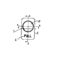
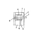
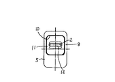
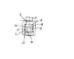
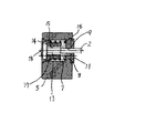
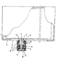
【解決手段】機器のスライド式スイッチやスライド式ボリューム等のスライド式操作部材3に用いられる摘みであり、前記機器の格納ケースのガイド溝5から突出する前記スライド部材の先端部に固着された固定軸15と、前記固定軸の外側に嵌合され、前記スライド式操作部材の長さ方向に沿って移動可能な摘み本体と、前記摘み本体の背面に装着されたゴムプレート12と、前記固定軸と前記摘み本体間の筒状空間部に収容され、前記摘み本体を前記格納ケースの外面に向かって移動付勢する圧縮コイルバネ17とからなる。前記格納ケースの外面に押し付けた前記ゴムプレートの摩擦接触抵抗によって前記摘み本体を当初の設定位置に停止保持する。
【選択図】図6
Description
Claims (1)
- 機器のスライド式スイッチやスライド式ボリューム等のスライド式操作部材に用いられる摘みであって、前記機器の格納ケースのガイド溝から突出する前記スライド式操作部材の先端部に固着された固定軸と、前記固定軸の外側に嵌合され、前記スライド式操作部材の長さ方向に沿って移動可能な摘み本体と、前記摘み本体の背面に装着されたゴムプレートと、前記固定軸と前記摘み本体間の筒状空間部に収容され、前記摘み本体を前記格納ケースの外面に向かって移動付勢する圧縮コイルバネとからなり、前記格納ケースの外面に押し付けた前記ゴムプレートの摩擦接触抵抗によって前記摘み本体を当初の設定位置に停止保持するようにしたスライド式操作部材用摘み。
Priority Applications (1)
| Application Number | Priority Date | Filing Date | Title |
|---|---|---|---|
| JP2008324928A JP4646082B2 (ja) | 2008-12-22 | 2008-12-22 | スライド式操作部材用摘み |
Applications Claiming Priority (1)
| Application Number | Priority Date | Filing Date | Title |
|---|---|---|---|
| JP2008324928A JP4646082B2 (ja) | 2008-12-22 | 2008-12-22 | スライド式操作部材用摘み |
Publications (2)
| Publication Number | Publication Date |
|---|---|
| JP2010146928A true JP2010146928A (ja) | 2010-07-01 |
| JP4646082B2 JP4646082B2 (ja) | 2011-03-09 |
Family
ID=42567104
Family Applications (1)
| Application Number | Title | Priority Date | Filing Date |
|---|---|---|---|
| JP2008324928A Active JP4646082B2 (ja) | 2008-12-22 | 2008-12-22 | スライド式操作部材用摘み |
Country Status (1)
| Country | Link |
|---|---|
| JP (1) | JP4646082B2 (ja) |
Citations (3)
| Publication number | Priority date | Publication date | Assignee | Title |
|---|---|---|---|---|
| JPS5752027U (ja) * | 1980-09-10 | 1982-03-25 | ||
| JPS62106438U (ja) * | 1985-12-24 | 1987-07-07 | ||
| JP2000195360A (ja) * | 1998-12-25 | 2000-07-14 | Canon Inc | キ―入力装置 |
-
2008
- 2008-12-22 JP JP2008324928A patent/JP4646082B2/ja active Active
Patent Citations (3)
| Publication number | Priority date | Publication date | Assignee | Title |
|---|---|---|---|---|
| JPS5752027U (ja) * | 1980-09-10 | 1982-03-25 | ||
| JPS62106438U (ja) * | 1985-12-24 | 1987-07-07 | ||
| JP2000195360A (ja) * | 1998-12-25 | 2000-07-14 | Canon Inc | キ―入力装置 |
Also Published As
| Publication number | Publication date |
|---|---|
| JP4646082B2 (ja) | 2011-03-09 |
Similar Documents
| Publication | Publication Date | Title |
|---|---|---|
| US7515930B2 (en) | Electronic device sliding mechanism | |
| WO2018041270A1 (zh) | 一种产生按压声音的键盘开关 | |
| MY206437A (en) | An aerosol-generating device comprising a cover element mechanism | |
| MY151565A (en) | Ejector of a moveable furniture part | |
| US20100124955A1 (en) | Sliding-type portable terminal | |
| TW201537599A (zh) | 電子裝置 | |
| US10050455B2 (en) | Structure with detachable battery for electronic device | |
| JP2018107088A (ja) | スイッチの接点構造、トリガースイッチ及び電動工具 | |
| JP4646082B2 (ja) | スライド式操作部材用摘み | |
| EP3815846A1 (en) | Driving machine | |
| JP4233978B2 (ja) | 弾球遊技機 | |
| JP2009529959A5 (ja) | ||
| US20120045077A1 (en) | Microphone device | |
| US10948126B2 (en) | Hand-held device | |
| US10919099B2 (en) | Hand-held device | |
| SG128643A1 (en) | Timepiece including a control device for a striking mechanism fitted with a resilient transmission element | |
| ES2567040T3 (es) | Mecanismo de botón de disparo de mando externo para disyuntor | |
| JP2001307574A (ja) | 防水ハウジングの操作ボタン構造 | |
| TW201342125A (zh) | 按鍵模組及電子裝置 | |
| ATE544642T1 (de) | Schlitzvorrichtung für ein wegfahrsicherungsauthentifizierungssystem | |
| KR101732147B1 (ko) | 햅틱 스타일러스 | |
| JP2009024328A (ja) | ドアストライク装置 | |
| JP6014518B2 (ja) | 穿刺装置 | |
| JP3125274U (ja) | 座標信号出力装置 | |
| DE602004000689D1 (de) | Tastschalter |
Legal Events
| Date | Code | Title | Description |
|---|---|---|---|
| A977 | Report on retrieval |
Free format text: JAPANESE INTERMEDIATE CODE: A971007 Effective date: 20101126 |
|
| TRDD | Decision of grant or rejection written | ||
| A01 | Written decision to grant a patent or to grant a registration (utility model) |
Free format text: JAPANESE INTERMEDIATE CODE: A01 Effective date: 20101201 |
|
| A01 | Written decision to grant a patent or to grant a registration (utility model) |
Free format text: JAPANESE INTERMEDIATE CODE: A01 |
|
| A61 | First payment of annual fees (during grant procedure) |
Free format text: JAPANESE INTERMEDIATE CODE: A61 Effective date: 20101201 |
|
| FPAY | Renewal fee payment (event date is renewal date of database) |
Free format text: PAYMENT UNTIL: 20131217 Year of fee payment: 3 |
|
| R150 | Certificate of patent or registration of utility model |
Ref document number: 4646082 Country of ref document: JP Free format text: JAPANESE INTERMEDIATE CODE: R150 Free format text: JAPANESE INTERMEDIATE CODE: R150 |
|
| R250 | Receipt of annual fees |
Free format text: JAPANESE INTERMEDIATE CODE: R250 |
|
| R250 | Receipt of annual fees |
Free format text: JAPANESE INTERMEDIATE CODE: R250 |