JP2010146928A - Knob for slide operation member - Google Patents
Knob for slide operation member Download PDFInfo
- Publication number
- JP2010146928A JP2010146928A JP2008324928A JP2008324928A JP2010146928A JP 2010146928 A JP2010146928 A JP 2010146928A JP 2008324928 A JP2008324928 A JP 2008324928A JP 2008324928 A JP2008324928 A JP 2008324928A JP 2010146928 A JP2010146928 A JP 2010146928A
- Authority
- JP
- Japan
- Prior art keywords
- knob
- slide
- storage case
- operation member
- main body
- Prior art date
- Legal status (The legal status is an assumption and is not a legal conclusion. Google has not performed a legal analysis and makes no representation as to the accuracy of the status listed.)
- Granted
Links
Images
Landscapes
- Slide Switches (AREA)
Abstract
【課題】簡単な構造によって当初の設定位置に安定に停止保持できるスライド式操作部材用摘みを提供する。
【解決手段】機器のスライド式スイッチやスライド式ボリューム等のスライド式操作部材3に用いられる摘みであり、前記機器の格納ケースのガイド溝5から突出する前記スライド部材の先端部に固着された固定軸15と、前記固定軸の外側に嵌合され、前記スライド式操作部材の長さ方向に沿って移動可能な摘み本体と、前記摘み本体の背面に装着されたゴムプレート12と、前記固定軸と前記摘み本体間の筒状空間部に収容され、前記摘み本体を前記格納ケースの外面に向かって移動付勢する圧縮コイルバネ17とからなる。前記格納ケースの外面に押し付けた前記ゴムプレートの摩擦接触抵抗によって前記摘み本体を当初の設定位置に停止保持する。
【選択図】図6Provided is a slide-type operating member knob that can be stably stopped and held at an initial set position by a simple structure.
A knob used for a slide-type operation member 3 such as a slide-type switch or a slide-type volume of a device, and is fixed to a distal end portion of the slide member protruding from a guide groove 5 of a storage case of the device. A shaft 15, a knob main body fitted to the outside of the fixed shaft and movable along the length direction of the sliding operation member, a rubber plate 12 mounted on the back surface of the knob main body, and the fixed shaft And a compression coil spring 17 that is accommodated in a cylindrical space between the knob bodies and moves and urges the knob body toward the outer surface of the storage case. The knob main body is stopped and held at the initial set position by the frictional contact resistance of the rubber plate pressed against the outer surface of the storage case.
[Selection] Figure 6
Description
本発明は、各種機器のスライド式スイッチやスライド式ボリューム等のスライド式操作部材に使用される摘みに関するものである。 The present invention relates to a knob used for a slide operation member such as a slide switch or a slide volume of various devices.
恒温槽等の試験機器においては、試験の前提条件である温度調節等は試験結果を左右する重要なファクタであるが、試験機器の温度調節機構のスライド式操作部材の摘みは、機器格納ケースの外側に単に突出して配置されているだけであるため、機器格納ケースの扉の開閉時の衝撃、周囲環境からの外部振動、衣服や器材の不用意な接触によって、摘みが当初の設定位置から無意図的に変更されてしまい、試験の前提条件の変動によって所期の試験結果を得られないことがあり、再実験を余儀なくされることがある。 In test equipment such as a thermostatic chamber, temperature control, which is a precondition for testing, is an important factor that affects the test results. Since it is merely protruding outward, the knob will not be removed from the original setting position due to impacts when opening and closing the door of the equipment storage case, external vibration from the surrounding environment, and inadvertent contact with clothes and equipment. It may be changed intentionally, and the test results may not be obtained due to changes in test assumptions, which may necessitate re-experiment.
電子機器に適用されるスライド操作機構及びスライド摘みとして、操作者にスライド式スイッチの切り換えをはっきり認識させるために良好なクリック感を与えるようにしたものが既に開発されているが(特許文献1参照)、スライド式操作部材の摘みを当初の設定位置に安定に停止保持するようにした技術は未だ提案されていない。 As a slide operation mechanism and a slide knob applied to an electronic device, a device that gives a good click feeling to the operator to clearly recognize the switching of the slide switch has been developed (see Patent Document 1). ), And a technique for stably stopping and holding the sliding operation member at the original set position has not yet been proposed.
本発明の課題は、簡単な構造によって当初の設定位置に安定に停止保持できるようにしたスライド式操作部材用摘みを提供することである。 An object of the present invention is to provide a slide-type operating member knob that can be stably stopped and held at an initial set position by a simple structure.
本発明の対象は、機器のスライド式スイッチやスライド式ボリューム等のスライド式操作部材に用いられる摘みであって、前記機器の格納ケースのガイド溝から突出する前記スライド部材の先端部に固着された固定軸と、前記固定軸の外側に嵌合され、前記スライド式操作部材の長さ方向に沿って移動可能な摘み本体と、前記摘み本体の背面に装着されたゴムプレートと、前記固定軸と前記摘み本体間の筒状空間部に収容され、前記摘み本体を前記格納ケースの外面に向かって移動付勢する圧縮コイルバネとからなり、前記格納ケースの外面に押し付けた前記ゴムプレートの摩擦接触抵抗によって前記摘み本体を当初の設定位置に停止保持するようにしたものである。 The object of the present invention is a knob used for a slide-type operation member such as a slide-type switch or a slide-type volume of a device, and is fixed to the tip of the slide member protruding from a guide groove of a storage case of the device A fixed shaft, a knob main body fitted to the outside of the fixed shaft and movable along the length direction of the sliding operation member, a rubber plate mounted on the back surface of the knob main body, and the fixed shaft Friction contact resistance of the rubber plate, which is accommodated in a cylindrical space between the knob bodies and includes a compression coil spring that moves and urges the knob body toward the outer surface of the storage case, and is pressed against the outer surface of the storage case Thus, the knob main body is stopped and held at the initial set position.
本発明のスライド式操作部材用摘みは、機器格納ケースのガイド溝から突出するスライド式操作部材の先端部に固定軸を固着し、前記スライド式操作部材の長さ方向に沿って移動可能な摘み本体を前記固定軸に嵌合し、前記固定軸と前記摘み本体間の筒状空間部に収容した圧縮コイルバネによって前記摘み本体を前記格納ケースの外面に向かって移動付勢したものであり、前記ガイド溝に沿って付されている目盛に従って所望の位置まで前記スライド式操作部材を動かした後、前記摘み本体から指を離すと、前記圧縮コイルバネの付勢によって前記摘み本体が前記格納ケースの外面に向かって移動し、前記摘み本体の背面に装着してあるゴムプレートが前記格納ケースの外面に押し付けられる。 The slide-type operation member knob of the present invention has a fixed shaft fixed to the tip of the slide-type operation member protruding from the guide groove of the device storage case, and is movable along the length direction of the slide-type operation member. The main body is fitted to the fixed shaft, and the knob main body is moved and urged toward the outer surface of the storage case by a compression coil spring accommodated in a cylindrical space between the fixed shaft and the knob main body. After moving the sliding operation member to a desired position according to the scale attached along the guide groove, when the finger is released from the knob main body, the knob main body is moved to the outer surface of the storage case by the bias of the compression coil spring. The rubber plate attached to the back surface of the knob body is pressed against the outer surface of the storage case.
前記格納ケースの外面に押し付けられた前記ゴムプレートと前記格納ケースとの間に働く十分に大きな摩擦接触抵抗によって前記摘み本体の動きが的確に制止されることになる。そのため、前記格納ケースの扉の開閉時の衝撃や周囲環境からの外部振動、衣服や器材の不用意な接触によって、スライド式操作部材の位置が当初の設定位置から無意図的に変更されてしまうことがないものである。 The movement of the knob body is accurately restrained by a sufficiently large frictional contact resistance acting between the rubber plate pressed against the outer surface of the storage case and the storage case. For this reason, the position of the sliding operation member is unintentionally changed from the initial set position due to an impact at the time of opening and closing the door of the storage case, external vibration from the surrounding environment, and inadvertent contact of clothes and equipment. There is nothing.
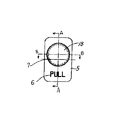
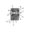
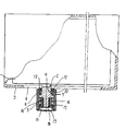
図示の実施例では、機器1のスライド式調整機構(図示していない)に接続された帯板状のスライド式操作部材2は、機器格納ケース3のガイド溝4から先端部が突出しており、当該先端部には直方体状の摘み本体5が装備されている。摘み本体5の前面下部には「PULL」という操作方向指示文字6が刻印されており、摘み本体5の前面上部には、円形空洞部7が内底壁8を残して前後方向に深く形成されている。内底壁8の中央部には、スライド式操作部材2が嵌挿される角孔9が前後方向に貫通して形成されている。
In the illustrated embodiment, the tip of the strip-type
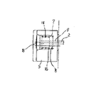
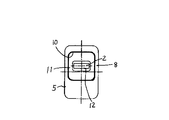
内底壁8の背面には矩形状の窪み10が形成されており、窪み10に収納された矩形状のゴムプレート11は内底壁8の背面に強固に接着されている。ゴムプレート11の中央部には、スライド式操作部材2の通過孔12が形成されている。スライド式操作部材2の最先端部分には雄ねじ部13が形成されている。円筒形状の固定軸14は、摘み本体5の空洞部7に余裕を残して挿入されており、中央部の雌ねじ部15にスライド式操作部材12の雄ねじ部13がねじ込み固着されている。
A
摘み本体5の内周面と固定軸14の外周面との間に残された前記空洞部7には、圧縮コイルバネ16が収納されており、圧縮コイルバネ16の前端は、固定軸14の前端鍔部17に当接し、圧縮コイルバネ16の後端は、摘み本体5の内底壁8の前面に当接している。摘み本体5の空洞部7の前端部には円盤状のキャップ18が嵌め込み固定されている。
A
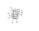
スライド式操作部材2を別の設定位置に移動させるときには、摘み本体5を手前に引いてゴムプレート11を格納ケース3の外面から引き離す。このとき、圧縮コイルバネ16は固定軸14の前端鍔部17と摘み本体5の内底壁8との間で更に圧縮負荷される。ガイド溝4に沿って付された目盛(図示していない)に従って摘み本体5を横に引き、スライド式操作部材2を所望の設定位置に移動させた後、摘み本体5から指を離すと、圧縮コイルバネ16の復元力によって摘み本体5が格納ケース3の外面に向かって移動し、ゴムプレート11が格納ケース3の外面に押し付けられる。
When the
摘み本体5がゴムプレート11と格納ケース3の間に働く摩擦接触抵抗によって新しい目盛位置に停止保持されるため、スライド式操作部材2も新しい設定位置に的確に停止保持される。
Since the
1 機器2 スライド式操作部材3 格納ケース4 ガイド溝5 摘み本体6 操作方向指示文字7 摘み本体の空洞部8 摘み本体の内底壁9 内底壁の角孔10 内底壁の窪み11 ゴムプレート12 ゴムプレートの通過孔13 スライド式操作部材の雄ねじ部14 固定軸15 固定軸の雌ねじ部16 圧縮コイルバネ17 固定軸の前端鍔部18 キャップ
DESCRIPTION OF SYMBOLS 1
Claims (1)
Priority Applications (1)
| Application Number | Priority Date | Filing Date | Title |
|---|---|---|---|
| JP2008324928A JP4646082B2 (en) | 2008-12-22 | 2008-12-22 | Knob for sliding operation member |
Applications Claiming Priority (1)
| Application Number | Priority Date | Filing Date | Title |
|---|---|---|---|
| JP2008324928A JP4646082B2 (en) | 2008-12-22 | 2008-12-22 | Knob for sliding operation member |
Publications (2)
| Publication Number | Publication Date |
|---|---|
| JP2010146928A true JP2010146928A (en) | 2010-07-01 |
| JP4646082B2 JP4646082B2 (en) | 2011-03-09 |
Family
ID=42567104
Family Applications (1)
| Application Number | Title | Priority Date | Filing Date |
|---|---|---|---|
| JP2008324928A Active JP4646082B2 (en) | 2008-12-22 | 2008-12-22 | Knob for sliding operation member |
Country Status (1)
| Country | Link |
|---|---|
| JP (1) | JP4646082B2 (en) |
Citations (3)
| Publication number | Priority date | Publication date | Assignee | Title |
|---|---|---|---|---|
| JPS5752027U (en) * | 1980-09-10 | 1982-03-25 | ||
| JPS62106438U (en) * | 1985-12-24 | 1987-07-07 | ||
| JP2000195360A (en) * | 1998-12-25 | 2000-07-14 | Canon Inc | Key input device |
-
2008
- 2008-12-22 JP JP2008324928A patent/JP4646082B2/en active Active
Patent Citations (3)
| Publication number | Priority date | Publication date | Assignee | Title |
|---|---|---|---|---|
| JPS5752027U (en) * | 1980-09-10 | 1982-03-25 | ||
| JPS62106438U (en) * | 1985-12-24 | 1987-07-07 | ||
| JP2000195360A (en) * | 1998-12-25 | 2000-07-14 | Canon Inc | Key input device |
Also Published As
| Publication number | Publication date |
|---|---|
| JP4646082B2 (en) | 2011-03-09 |
Similar Documents
| Publication | Publication Date | Title |
|---|---|---|
| US7515930B2 (en) | Electronic device sliding mechanism | |
| MY206437A (en) | An aerosol-generating device comprising a cover element mechanism | |
| MY151565A (en) | Ejector of a moveable furniture part | |
| WO2018041270A1 (en) | Keyboard switch which produces press sound | |
| TW201537599A (en) | Electronic device | |
| JP2018107088A (en) | Contact structure of switch, trigger switch, and power tool | |
| JP4646082B2 (en) | Knob for sliding operation member | |
| EP3815846A1 (en) | Driving machine | |
| US7961177B2 (en) | Input pen storage | |
| JP2009529959A5 (en) | ||
| US20120045077A1 (en) | Microphone device | |
| JP2011249282A (en) | Key switch device and keyboard | |
| US10948126B2 (en) | Hand-held device | |
| US10919099B2 (en) | Hand-held device | |
| ES2567040T3 (en) | External control trigger button mechanism for circuit breaker | |
| KR100818782B1 (en) | Mechanical pencil | |
| JP2001307574A (en) | Operation button structure of waterproof housing | |
| US20130256106A1 (en) | Button mechanism and electronic device using the same | |
| ATE544642T1 (en) | SLOT DEVICE FOR AN IMMOBILIZER AUTHENTICATION SYSTEM | |
| KR101732147B1 (en) | Haptic stylus | |
| JP2009024328A (en) | Door strike device | |
| JP6014518B2 (en) | Puncture device | |
| TW201342410A (en) | Button module and electronic device | |
| JP2008198501A (en) | Control mode switch of portable apparatus | |
| JP3125274U (en) | Coordinate signal output device |
Legal Events
| Date | Code | Title | Description |
|---|---|---|---|
| A977 | Report on retrieval |
Free format text: JAPANESE INTERMEDIATE CODE: A971007 Effective date: 20101126 |
|
| TRDD | Decision of grant or rejection written | ||
| A01 | Written decision to grant a patent or to grant a registration (utility model) |
Free format text: JAPANESE INTERMEDIATE CODE: A01 Effective date: 20101201 |
|
| A01 | Written decision to grant a patent or to grant a registration (utility model) |
Free format text: JAPANESE INTERMEDIATE CODE: A01 |
|
| A61 | First payment of annual fees (during grant procedure) |
Free format text: JAPANESE INTERMEDIATE CODE: A61 Effective date: 20101201 |
|
| FPAY | Renewal fee payment (event date is renewal date of database) |
Free format text: PAYMENT UNTIL: 20131217 Year of fee payment: 3 |
|
| R150 | Certificate of patent or registration of utility model |
Ref document number: 4646082 Country of ref document: JP Free format text: JAPANESE INTERMEDIATE CODE: R150 Free format text: JAPANESE INTERMEDIATE CODE: R150 |
|
| R250 | Receipt of annual fees |
Free format text: JAPANESE INTERMEDIATE CODE: R250 |