JP2010146905A - Lighting fixture for vehicle - Google Patents
Lighting fixture for vehicle Download PDFInfo
- Publication number
- JP2010146905A JP2010146905A JP2008324279A JP2008324279A JP2010146905A JP 2010146905 A JP2010146905 A JP 2010146905A JP 2008324279 A JP2008324279 A JP 2008324279A JP 2008324279 A JP2008324279 A JP 2008324279A JP 2010146905 A JP2010146905 A JP 2010146905A
- Authority
- JP
- Japan
- Prior art keywords
- lens
- lamp
- light shielding
- multicolor
- shielding wall
- Prior art date
- Legal status (The legal status is an assumption and is not a legal conclusion. Google has not performed a legal analysis and makes no representation as to the accuracy of the status listed.)
- Pending
Links
Images


Classifications
-
- B—PERFORMING OPERATIONS; TRANSPORTING
- B60—VEHICLES IN GENERAL
- B60Q—ARRANGEMENT OF SIGNALLING OR LIGHTING DEVICES, THE MOUNTING OR SUPPORTING THEREOF OR CIRCUITS THEREFOR, FOR VEHICLES IN GENERAL
- B60Q1/00—Arrangement of optical signalling or lighting devices, the mounting or supporting thereof or circuits therefor
- B60Q1/26—Arrangement of optical signalling or lighting devices, the mounting or supporting thereof or circuits therefor the devices being primarily intended to indicate the vehicle, or parts thereof, or to give signals, to other traffic
- B60Q1/2607—Arrangement of optical signalling or lighting devices, the mounting or supporting thereof or circuits therefor the devices being primarily intended to indicate the vehicle, or parts thereof, or to give signals, to other traffic comprising at least two indicating lamps
-
- F—MECHANICAL ENGINEERING; LIGHTING; HEATING; WEAPONS; BLASTING
- F21—LIGHTING
- F21S—NON-PORTABLE LIGHTING DEVICES; SYSTEMS THEREOF; VEHICLE LIGHTING DEVICES SPECIALLY ADAPTED FOR VEHICLE EXTERIORS
- F21S43/00—Signalling devices specially adapted for vehicle exteriors, e.g. brake lamps, direction indicator lights or reversing lights
- F21S43/20—Signalling devices specially adapted for vehicle exteriors, e.g. brake lamps, direction indicator lights or reversing lights characterised by refractors, transparent cover plates, light guides or filters
- F21S43/255—Filters
-
- F—MECHANICAL ENGINEERING; LIGHTING; HEATING; WEAPONS; BLASTING
- F21—LIGHTING
- F21S—NON-PORTABLE LIGHTING DEVICES; SYSTEMS THEREOF; VEHICLE LIGHTING DEVICES SPECIALLY ADAPTED FOR VEHICLE EXTERIORS
- F21S43/00—Signalling devices specially adapted for vehicle exteriors, e.g. brake lamps, direction indicator lights or reversing lights
- F21S43/20—Signalling devices specially adapted for vehicle exteriors, e.g. brake lamps, direction indicator lights or reversing lights characterised by refractors, transparent cover plates, light guides or filters
- F21S43/26—Refractors, transparent cover plates, light guides or filters not provided in groups F21S43/235 - F21S43/255
-
- F—MECHANICAL ENGINEERING; LIGHTING; HEATING; WEAPONS; BLASTING
- F21—LIGHTING
- F21S—NON-PORTABLE LIGHTING DEVICES; SYSTEMS THEREOF; VEHICLE LIGHTING DEVICES SPECIALLY ADAPTED FOR VEHICLE EXTERIORS
- F21S43/00—Signalling devices specially adapted for vehicle exteriors, e.g. brake lamps, direction indicator lights or reversing lights
- F21S43/20—Signalling devices specially adapted for vehicle exteriors, e.g. brake lamps, direction indicator lights or reversing lights characterised by refractors, transparent cover plates, light guides or filters
- F21S43/27—Attachment thereof
-
- F—MECHANICAL ENGINEERING; LIGHTING; HEATING; WEAPONS; BLASTING
- F21—LIGHTING
- F21S—NON-PORTABLE LIGHTING DEVICES; SYSTEMS THEREOF; VEHICLE LIGHTING DEVICES SPECIALLY ADAPTED FOR VEHICLE EXTERIORS
- F21S43/00—Signalling devices specially adapted for vehicle exteriors, e.g. brake lamps, direction indicator lights or reversing lights
- F21S43/50—Signalling devices specially adapted for vehicle exteriors, e.g. brake lamps, direction indicator lights or reversing lights characterised by aesthetic components not otherwise provided for, e.g. decorative trim, partition walls or covers
Landscapes
- Engineering & Computer Science (AREA)
- General Engineering & Computer Science (AREA)
- Mechanical Engineering (AREA)
- Non-Portable Lighting Devices Or Systems Thereof (AREA)
Abstract
【課題】可撓性レンズが撓み変形しても、そのレンズ面が傷付くのを防止できる車両用灯具の提供を課題とする。
【解決手段】光源30が収容された複数の灯室40と、複数の灯室40を仕切る遮光壁42、44と、複数の灯室40を塞ぐように設けられるとともに、遮光壁42、44と対向するレンズ面58に、レンズ面58と交差する方向へ突出する突出部56が形成された可撓性レンズ50と、遮光壁42、44に設けられ、突出部56をその厚さ方向に押圧する押圧部46と、を備えた車両用灯具20とする。
【選択図】図4An object of the present invention is to provide a vehicular lamp that can prevent the lens surface from being damaged even when the flexible lens is bent and deformed.
SOLUTION: A plurality of lamp chambers 40 in which a light source 30 is accommodated, light shielding walls 42 and 44 for partitioning the plurality of lamp chambers 40, and provided so as to close the plurality of lamp chambers 40, and the light shielding walls 42 and 44, A flexible lens 50 having a protruding portion 56 protruding in a direction intersecting the lens surface 58 on the opposite lens surface 58 and the light shielding walls 42 and 44 are provided, and the protruding portion 56 is pressed in the thickness direction. It is set as the vehicle lamp 20 provided with the press part 46 to perform.
[Selection] Figure 4
Description
本発明は、リアコンビネーションランプ等の車両用灯具に関する。 The present invention relates to a vehicular lamp such as a rear combination lamp.
リアコンビネーションランプ等の多色レンズを備えた車両用灯具において、複数の灯室を仕切る遮光リブが、多色レンズの異なるランプ機能色の境界部に対向する位置に設けられた構成は、従来から知られている(例えば、特許文献1参照)。
しかしながら、その多色レンズが、例えばフィルム状のシート部材を真空成形することによって形成された可撓性レンズである場合、その可撓性レンズが撓み変形したときには、遮光リブにレンズ面が干渉するため、そのレンズ面に擦れ傷などが発生してしまう。 However, when the multicolor lens is a flexible lens formed by vacuum forming a film-like sheet member, for example, when the flexible lens is bent and deformed, the lens surface interferes with the light shielding rib. As a result, scratches and the like are generated on the lens surface.
そこで、本発明は、上記事情に鑑み、可撓性レンズが撓み変形しても、そのレンズ面が傷付くのを防止できる車両用灯具を得ることを目的とする。 Therefore, in view of the above circumstances, an object of the present invention is to obtain a vehicular lamp that can prevent the lens surface from being damaged even if the flexible lens is bent and deformed.
上記の目的を達成するために、本発明に係る請求項1に記載の車両用灯具は、光源が収容された複数の灯室と、前記複数の灯室を仕切る遮光壁と、前記複数の灯室を塞ぐように設けられるとともに、前記遮光壁と対向するレンズ面に、該レンズ面と交差する方向へ突出する突出部が形成された可撓性レンズと、前記遮光壁に設けられ、前記突出部をその厚さ方向に押圧する押圧部と、を備えたことを特徴としている。 In order to achieve the above object, a vehicular lamp according to claim 1 of the present invention includes a plurality of lamp chambers in which a light source is accommodated, a light shielding wall that partitions the plurality of lamp chambers, and the plurality of lamps. A flexible lens having a lens surface facing the light shielding wall and a projecting portion projecting in a direction intersecting with the lens surface; and the light shielding wall. And a pressing portion that presses the portion in the thickness direction.
請求項1に記載の発明によれば、突出部を除く可撓性レンズが撓み変形しようとしても、遮光壁に設けられた押圧部が突出部への押圧接触を維持するので、その可撓性レンズのレンズ面が遮光壁に干渉することはない。したがって、可撓性レンズのレンズ面が傷付くのを防止することができる。 According to the first aspect of the present invention, even if the flexible lens excluding the projecting portion tries to bend and deform, the pressing portion provided on the light shielding wall maintains the pressing contact with the projecting portion. The lens surface of the lens does not interfere with the light shielding wall. Therefore, the lens surface of the flexible lens can be prevented from being damaged.
また、請求項2に記載の車両用灯具は、請求項1に記載の車両用灯具において、前記突出部が、前記可撓性レンズの裏面側へ突出し、前記押圧部が、前記突出部をその厚さ方向外側から狭持するリブを有することを特徴としている。 According to a second aspect of the present invention, there is provided the vehicular lamp according to the first aspect, wherein the projecting portion projects toward the back side of the flexible lens, and the pressing portion projects the projecting portion. It is characterized by having a rib sandwiched from the outside in the thickness direction.
請求項2に記載の発明によれば、突出部を除く可撓性レンズが撓み変形しようとしても、遮光壁に設けられたリブが突出部をその厚さ方向外側から狭持して、突出部への押圧接触を維持するので、その可撓性レンズのレンズ面が遮光壁に干渉することはない。したがって、可撓性レンズのレンズ面が傷付くのを防止することができる。 According to the second aspect of the present invention, even if the flexible lens excluding the projecting portion tries to bend and deform, the rib provided on the light shielding wall holds the projecting portion from the outside in the thickness direction, and the projecting portion Since the pressing contact is maintained, the lens surface of the flexible lens does not interfere with the light shielding wall. Therefore, the lens surface of the flexible lens can be prevented from being damaged.
また、請求項3に記載の車両用灯具は、請求項1に記載の車両用灯具において、前記突出部が、前記可撓性レンズの表面側へ突出し、前記押圧部が、前記突出部内の空間に、該突出部内の対向している壁面を押し広げるように挿入されるリブを有することを特徴としている。 According to a third aspect of the present invention, there is provided the vehicular lamp according to the first aspect, wherein the protruding portion protrudes toward the surface of the flexible lens, and the pressing portion is a space in the protruding portion. And a rib that is inserted so as to spread the opposing wall surface in the projecting portion.
請求項3に記載の発明によれば、突出部を除く可撓性レンズが撓み変形しようとしても、遮光壁に設けられたリブが突出部内の空間に挿入され、その対向している壁面を押し広げて、突出部への押圧接触を維持するので、その可撓性レンズのレンズ面が遮光壁に干渉することはない。したがって、可撓性レンズのレンズ面が傷付くのを防止することができる。また、この場合、遮光壁は突出部内の空間に挿入されるので、その厚さは小さく、発光されない領域であるダミー領域(ダミー寸法)を減少させることができる。 According to the third aspect of the present invention, even if the flexible lens excluding the projecting portion tries to bend and deform, the rib provided on the light shielding wall is inserted into the space in the projecting portion, and the opposing wall surface is pushed. Since it is spread and the pressing contact with the protruding portion is maintained, the lens surface of the flexible lens does not interfere with the light shielding wall. Therefore, the lens surface of the flexible lens can be prevented from being damaged. In this case, since the light shielding wall is inserted into the space in the protruding portion, the thickness of the light shielding wall is small, and the dummy region (dummy dimension) that is a region where no light is emitted can be reduced.
以上のように、本発明によれば、可撓性レンズが撓み変形しても、そのレンズ面が傷付くのを防止できる車両用灯具を提供することができる。 As described above, according to the present invention, it is possible to provide a vehicular lamp that can prevent the lens surface from being damaged even when the flexible lens is bent and deformed.
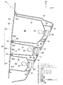
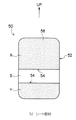
以下、本発明の最良な実施の形態について、図面に示す実施例を基に詳細に説明する。まず、第1実施例について説明する。図1は車両の車体後部側を示す概略斜視図であり、図2は本実施形態に係る車両用灯具(リアコンビネーションランプ20)を示す概略側断面図である。そして、図3は第1実施例の可撓性レンズ(多色レンズ50)を示す概略正面図である。 DESCRIPTION OF THE PREFERRED EMBODIMENTS The best mode for carrying out the present invention will be described below in detail based on the embodiments shown in the drawings. First, the first embodiment will be described. FIG. 1 is a schematic perspective view showing the rear side of the vehicle body of the vehicle, and FIG. 2 is a schematic side sectional view showing a vehicular lamp (rear combination lamp 20) according to the present embodiment. FIG. 3 is a schematic front view showing the flexible lens (multicolor lens 50) of the first embodiment.
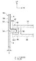
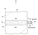
また、図4は第1実施例の可撓性レンズ(多色レンズ50)の突出部と遮光壁の押圧部を示す概略側断面図であり、図5は第1実施例の可撓性レンズ(多色レンズ50)の突出部と遮光壁の押圧部を示す概略正面図である。なお、各図において適宜示す矢印UPは車体上方向を示し、矢印FRは車体前方向を示す。 FIG. 4 is a schematic sectional side view showing the protruding portion of the flexible lens (multicolor lens 50) of the first embodiment and the pressing portion of the light shielding wall, and FIG. 5 is the flexible lens of the first embodiment. It is a schematic front view which shows the protrusion part of the (multicolor lens 50), and the press part of a light-shielding wall. In each drawing, an arrow UP appropriately indicates the vehicle body upward direction, and an arrow FR indicates the vehicle body front direction.
図1で示すように、車両10の車体後方側端部には、リアバンパ14が車幅方向に配置されている。そして、リアバンパ14の車体上方側で、かつ車幅方向両端部には、車両用灯具の一例としてのリアコンビネーションランプ20が左右一対で配置されている。このリアコンビネーションランプ20においては、テールランプ(ブレーキランプ)22、バックアップランプ24、リアターンシグナルランプ26が車体上下方向に並設されている(図2参照)。
As shown in FIG. 1, a
また、図2で示すように、テールランプ22、バックアップランプ24、リアターンシグナルランプ26は、それぞれのランプハウジング32、34、36内に、光源(例えばバルブやLED(発光ダイオード)等)30と、光源30からの拡散光を反射したり、後方車両のヘッドランプから照射された光を反射する反射板である凹鏡面状のリフレクタ(図示省略)と、を収容している。
In addition, as shown in FIG. 2, the
光源30からの光を照射可能に開口された各ランプハウジング32、34、36の裏面には、支持突起38が複数個ずつ突設されており、各支持突起38が、車体12のリアエンドパネル16に固着された複数の支持部材18に、それぞれ支持されるようになっている。これにより、各ランプハウジング32、34、36が車体12に対して固定される構成である。
A plurality of
そして、各ランプハウジング32、34、36の略中央位置には、光源30を装着するためのソケット(バックカバー)28が取り付けられている。ソケット28には、各ランプハウジング32、34、36の裏側となる車体前方側へ向けて電極が突設されており、この電極に電気配線(図示省略)が接続されて、光源30へ通電可能とされている。
A socket (back cover) 28 for mounting the
また、真ん中に位置するランプハウジング34の開口部34Aの上端部と、上側に位置するランプハウジング32の開口部32Aの下端部とが一体に連結され、真ん中に位置するランプハウジング34の開口部34Aの下端部と、下側に位置するランプハウジング36の開口部36Aの上端部とが一体に連結されており、各連結部分によって、各灯室40を仕切る遮光壁42、44がそれぞれ形成されるようになっている。
Further, the upper end portion of the
また、各ランプハウジング32、34、36の開口部32A、34A、36Aを閉塞し、各ランプハウジング32、34、36毎に灯室40を形成する可撓性レンズとしての樹脂製の多色レンズ50が単一で設けられている。この多色レンズ50は、光源30から発せられ、図示しないリフレクタにより反射された光を透過させて発光させるようになっており、各灯室40別のランプ機能色に色分けされている。
Also, resin multicolor lenses as flexible lenses that close the
すなわち、この多色レンズ50は、図4で示すように、ランプ機能色(本実施例では赤色Rと黄色Y)が裏面の所定位置に印刷された半透明(又は透明)なフィルム状のシート部材52を、真空成形することによって形成されており、例えば図3で示すように、上側のテールランプ22が赤色Rとされ、中央のバックアップランプ24が半透明色(クリア色)Sとされ、下側のリアターンシグナルランプ26が黄色(アンバー色)Yとされている。
That is, as shown in FIG. 4, the
そして、異なるランプ機能色間(赤色R部位と半透明色S部位の間及び半透明色S部位と黄色Y部位の間)が、それぞれ遮光壁42、44と対向する境界部(見切り部)54とされている。また、この多色レンズ50の各境界部54の裏面側には、図4で示すように、レンズ面58に沿った方向と交差する方向に所定長さ突出した突出部56が一体に形成されている。
The boundary portions (parting portions) 54 between the different lamp function colors (between the red R portion and the semi-transparent color S portion and between the translucent color S portion and the yellow Y portion) face the
つまり、フィルム状のシート部材52の各境界部54に相当する部分を裏面側へ折り込むようにして真空成形することにより、突出部56が形成されるようになっている。そして、各突出部56の先端部(車体前方側端部)は、図4、図5で示すように、各遮光壁42、44の先端部(車体後方側端部)に設けられた押圧部としての複数のリブ46間に、それぞれ圧入(挿入)されるようになっている。
That is, the projecting
すなわち、各遮光壁42、44の先端部には、車体上下方向において互いに対向する断面略半円弧状のリブ46が、それぞれの突出部56に沿って(車幅方向に)所定間隔を隔てて(例えば等間隔に)複数形成されており、各リブ46の車体上下方向における間隔Wは、突出部56の厚さE未満とされている(W<E)。したがって、突出部56は、その上下のリブ46間に圧入され、それによって、突出部56の厚さ方向外側から、つまり、車体上方側及び車体下方側から狭持(押圧)されるようになっている。
That is,
また、この突出部56は、真空成形時において、フィルム状のシート部材52が不均一に伸張しても、各境界部54のレンズ面58に沿った方向における不均一な位置ずれ(ばらつき)を吸収できるようになっており、多色レンズ50において、赤色R部位と半透明色S部位及び半透明色S部位と黄色Y部位の各境界部54の位置が一定になるように(ばらつかないように)なっている。
In addition, even when the film-
また、こうして形成された多色レンズ50の板厚D(図4参照)は、例えばD=0.3mm〜1.0mmとされている。ここで、板厚Dの下限を0.3mmとしているのは、板厚Dが0.3mm未満の多色レンズ50を製造するのが困難であり、板厚Dの上限を1.0mmとしているのは、板厚Dが1.0mmより大きいと、フィルム状シート部材52の真空成形によって多色レンズ50を成形し難いからである。つまり、板厚Dを0.3mm〜1.0mmとすることにより、多色レンズ50を真空成形により容易に成形できる構成である。
Further, the plate thickness D (see FIG. 4) of the thus formed
以上のような構成のリアコンビネーションランプ(車両用灯具)20において、次にその作用について説明する。本実施例に係る多色レンズ50は、所定部位が赤色R及び黄色Yで印刷された半透明なフィルム状シート部材52を真空成形することによって形成されている。そして、この多色レンズ50には、フィルム状シート部材52の赤色R部位と半透明色S部位及び半透明色S部位と黄色Y部位の各境界部54に相当する部分がそれぞれ裏面側へ折り込まれるようにして真空成形されることにより、突出部56が形成されている。
Next, the operation of the rear combination lamp (vehicle lamp) 20 configured as described above will be described. The
一方、多色レンズ50の各境界部54(各突出部56)に対向する位置には、各灯室40を仕切る遮光壁42、44がそれぞれ配置され、その先端部には、車体上下方向に互いに対向し、かつ、その車体上下方向の間隔Wが突出部56の厚さE未満とされたリブ46が、突出部56に沿って(車幅方向に)所定間隔を隔てて(等間隔に)複数形成されている。したがって、多色レンズ50が各灯室40を塞ぐようにランプハウジング32、34、36に接合されたときには、各突出部56が各リブ46間に圧入される。
On the other hand,
これにより、突出部56を除く多色レンズ50が撓み変形しようとしても、遮光壁42、44に設けられたリブ46が、突出部56をその厚さ方向外側から、即ち車体上方側及び車体下方側から狭持(押圧)して、その押圧接触状態を維持するので、その多色レンズ50のレンズ面58が遮光壁42、44に干渉することはない。したがって、多色レンズ50のレンズ面58に擦れ傷などは発生しない。つまり、多色レンズ50のレンズ面58が遮光壁42、44によって傷付くのを防止することができる。
As a result, even if the
また、本実施形態に係る構成によれば、多色レンズ50の振動を抑制することが可能となる。すなわち、フィルム状シート部材52を真空成形することによって形成された多色レンズ50は、剛性が低いため、雨水等が当たると、振動して異音が発生するおそれがあるが、多色レンズ50に一体に形成された突出部56を、遮光壁42、44に設けたリブ46で押圧して保持することにより、多色レンズ50の振動を抑制することができ、異音の発生を抑制することができる。
Moreover, according to the configuration according to the present embodiment, it is possible to suppress the vibration of the
なお、遮光壁42、44の先端部に別途緩衝部材(図示省略)を設け、その緩衝部材で、多色レンズ50の境界部54を裏面側から押圧するようにしても、振動を抑制することができるが、この構成では、多色レンズ50が撓み変形したときに、緩衝部材に対して多色レンズ50のレンズ面58が相対的に摺動することがあるので、その裏面に擦れ傷が発生するおそれがある。また、その緩衝部材がレンズ越しに外部から見えるので、見映えがよくなく、緩衝部材の分だけ、部品点数が増加する問題もある。
Even if a buffer member (not shown) is separately provided at the tip of the
しかし、本実施形態に係る構成では、多色レンズ50が撓み変形しても、遮光壁42、44に対して、その多色レンズ50のレンズ面58が相対的に摺動することはない(干渉することがない)し、リブ46は、各遮光壁42、44の先端部にそれぞれ一体に形成され、上記した緩衝部材のように別途取り付けられる構成ではないため、部品点数や製造コストが増加する問題もなく、また、外部から見え難い構造となるため、見映えを損なう心配もない。
However, in the configuration according to the present embodiment, even if the
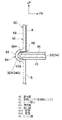
次に、第2実施例について説明する。なお、上記第1実施例と同等の部位には同じ符号を付して詳細な説明(共通の作用も含む)は適宜省略する。図6は第2実施例の可撓性レンズ(多色レンズ60)の突出部と遮光壁の押圧部を示す概略側断面図であり、図7は第2実施例の可撓性レンズ(多色レンズ60)の突出部と遮光壁の押圧部を示す概略正面図である。 Next, a second embodiment will be described. In addition, the same code | symbol is attached | subjected to the site | part equivalent to the said 1st Example, and detailed description (a common effect | action is also included) is abbreviate | omitted suitably. FIG. 6 is a schematic sectional side view showing the protruding portion of the flexible lens (multicolor lens 60) and the pressing portion of the light shielding wall of the second embodiment, and FIG. It is a schematic front view which shows the protrusion part of the color lens 60), and the press part of a light-shielding wall.
図6、図7で示すように、この第2実施例の多色レンズ60は、上記第1実施例の多色レンズ50とは逆に、その表面側に側面視略「U」字状の突出部66が形成されている。すなわち、この多色レンズ60も、上記と同様に、所定部位が赤色R及び黄色Yで印刷された半透明なフィルム状シート部材62を真空成形することによって形成され、その赤色R部位と半透明色S部位及び半透明色S部位と黄色Y部位との各境界部64には、それぞれ表面側へ折り込まれるようにして突出する突出部66が一体に形成されている。
As shown in FIGS. 6 and 7, the
また、この第2実施例では、ランプハウジング32、34の開口部32A、34A及びランプハウジング34、36の開口部34A、36Aをそれぞれ一体に連結するか、又は、ランプハウジング32、34の開口部32A、34Aの何れか一方及びランプハウジング34、36の開口部34A、36Aの何れか一方で、遮光壁48が構成されている。
Further, in this second embodiment, the
そして、各遮光壁48の先端部(車体後方側端部)における上面及び下面には、押圧部としてのリブ46が、それぞれの突出部66に沿って(車幅方向に)所定間隔を隔てて(例えば等間隔に)複数形成されており、この複数のリブ46を備えた遮光壁48の先端部が、突出部66の内部空間に挿入(圧入)されて、その突出部66の対向している壁面66A、66Bを押し広げるようになっている。
Then,
すなわち、このリブ46は、断面略半円弧状に形成され、各リブ46を含めた遮光壁48の厚さTは、突出部66の内面(裏面)側の高さHより厚く形成されている(H<T)。したがって、遮光壁48の先端部は、突出部66の裏面側から、その内部空間に圧入され、これによって、突出部66の対向している壁面66A、66Bが、車体上方向及び車体下方向へ、それぞれ押圧されるようになっている。
That is, the
よって、突出部66を除く多色レンズ60が撓み変形しようとしても、遮光壁48に設けられたリブ46が、突出部66の対向している壁面66A、66Bを押し広げて(車体上方向及び車体下方向へ押圧して)、その押圧接触状態を維持するので、その多色レンズ60のレンズ面68が遮光壁48に干渉することはない。したがって、多色レンズ60のレンズ面68に擦れ傷などは発生しない。つまり、多色レンズ60のレンズ面68が遮光壁48によって傷付くのを防止することができる。
Therefore, even if the
また、この第2実施例の場合、遮光壁48は、突出部66の内部空間に圧入(挿入)される構成であるため、その厚さは、上記第1実施例の遮光壁42、44の厚さよりも小さくなっている。したがって、発光されない領域であるダミー領域(ダミー寸法)を上記第1実施例よりも削減する(減少させる)ことができ、発光面積を拡大することができるため、多色レンズ60自体の縮小化(コンパクト化)が可能となる。よって、発光効率の良好なリアコンビネーションランプ20が得られ、リアコンビネーションランプ20自体の軽量化及び簡素化も可能となる。
In the case of the second embodiment, since the
また、この突出部66は、真空成形時において、フィルム状のシート部材62が不均一に伸張しても、境界部64のレンズ面68に沿った方向における不均一な位置ずれ(ばらつき)を吸収できるようになっており、多色レンズ60において、赤色R部位と半透明色S部位及び半透明色S部位と黄色Y部位の各境界部64の位置が一定になるように(ばらつかないように)なっている。また、この第2実施例においても、上記第1実施例と同様に、多色レンズ60の振動を抑制でき、異音の発生を抑制できることは言うまでもない。
Further, the
以上、本実施形態に係る車両用灯具をリアコンビネーションランプ20に適用した場合について説明したが、本実施形態に係る車両用灯具は、図示の各実施例に限定されるものではなく、本発明の要旨を逸脱しない範囲内において、適宜設計変更可能なものである。例えば、各実施例におけるリブ46は、図5、図7で示したように、上下で同じ位置に形成されているが、上下で異なる位置に形成されていてもよい。また、本実施形態に係る車両用灯具は、車両10に配設されるフォグランプ等を備えた他の車両用灯具にも適用が可能である。
As mentioned above, although the case where the vehicle lamp which concerns on this embodiment was applied to the
10 車両
20 リアコンビネーションランプ(車両用灯具)
22 テールランプ
24 バックアップランプ
26 リアターンシグナルランプ
30 光源
32 ランプハウジング
34 ランプハウジング
36 ランプハウジング
40 灯室
42 遮光壁
44 遮光壁
46 リブ(押圧部)
48 遮光壁
50 多色レンズ(可撓性レンズ)
52 シート部材
54 境界部
56 突出部
58 レンズ面
60 多色レンズ(可撓性レンズ)
62 シート部材
64 境界部
66 突出部
66A 壁面
66B 壁面
68 レンズ面
10
22
48 Light-shielding
52
62
Claims (3)
前記複数の灯室を仕切る遮光壁と、
前記複数の灯室を塞ぐように設けられるとともに、前記遮光壁と対向するレンズ面に、該レンズ面と交差する方向へ突出する突出部が形成された可撓性レンズと、
前記遮光壁に設けられ、前記突出部をその厚さ方向に押圧する押圧部と、
を備えたことを特徴とする車両用灯具。 A plurality of lamp rooms containing light sources;
A light shielding wall for partitioning the plurality of lamp chambers;
A flexible lens provided so as to close the plurality of lamp chambers, and having a protruding portion that protrudes in a direction intersecting the lens surface on a lens surface facing the light shielding wall;
A pressing portion provided on the light shielding wall and pressing the protruding portion in the thickness direction;
A vehicular lamp characterized by comprising:
前記押圧部が、前記突出部をその厚さ方向外側から狭持するリブを有することを特徴とする請求項1に記載の車両用灯具。 The protrusion protrudes toward the back side of the flexible lens;
The vehicular lamp according to claim 1, wherein the pressing portion includes a rib that sandwiches the protruding portion from the outside in the thickness direction.
前記押圧部が、前記突出部内の空間に、該突出部内の対向している壁面を押し広げるように挿入されるリブを有することを特徴とする請求項1に記載の車両用灯具。 The protrusion protrudes toward the surface of the flexible lens;
2. The vehicular lamp according to claim 1, wherein the pressing portion includes a rib that is inserted into a space in the projecting portion so as to expand an opposing wall surface in the projecting portion.
Priority Applications (1)
| Application Number | Priority Date | Filing Date | Title |
|---|---|---|---|
| JP2008324279A JP2010146905A (en) | 2008-12-19 | 2008-12-19 | Lighting fixture for vehicle |
Applications Claiming Priority (1)
| Application Number | Priority Date | Filing Date | Title |
|---|---|---|---|
| JP2008324279A JP2010146905A (en) | 2008-12-19 | 2008-12-19 | Lighting fixture for vehicle |
Publications (1)
| Publication Number | Publication Date |
|---|---|
| JP2010146905A true JP2010146905A (en) | 2010-07-01 |
Family
ID=42567088
Family Applications (1)
| Application Number | Title | Priority Date | Filing Date |
|---|---|---|---|
| JP2008324279A Pending JP2010146905A (en) | 2008-12-19 | 2008-12-19 | Lighting fixture for vehicle |
Country Status (1)
| Country | Link |
|---|---|
| JP (1) | JP2010146905A (en) |
-
2008
- 2008-12-19 JP JP2008324279A patent/JP2010146905A/en active Pending
Similar Documents
| Publication | Publication Date | Title |
|---|---|---|
| KR101125961B1 (en) | Vehicular lamp | |
| JP4609881B2 (en) | Side turn signal lamp | |
| CN101595009B (en) | Vehicle lamp | |
| JP5652482B2 (en) | Vehicle lamp structure | |
| JP5906050B2 (en) | Vehicle lighting | |
| CN101457892A (en) | Vehicle lamp assembly | |
| JP6576830B2 (en) | Vehicle lamp | |
| JP5986424B2 (en) | Vehicle headlamp | |
| US9857045B2 (en) | Vehicle lamp structure | |
| US10344939B2 (en) | Vehicle lighting assembly | |
| CN111412431A (en) | Vehicle lamp and motor vehicle | |
| JP2010146906A (en) | Lighting fixture for vehicle | |
| CN111527008A (en) | interior lighting | |
| JP5091930B2 (en) | Vehicle lamp | |
| JP2010153114A (en) | Method for manufacturing lamp for vehicle, and lamp for vehicle | |
| JP4158628B2 (en) | Vehicle lighting | |
| JP2018195443A (en) | Vehicle lighting | |
| JP2010153113A (en) | Method for manufacturing lamp for vehicle, lens of vehicle lamp, and sheet member for lens forming of vehicle lamp | |
| JP2607212Y2 (en) | Vehicle sign lights | |
| JP6456198B2 (en) | Positioning structure of parts in vehicular lamp | |
| JP6042657B2 (en) | Vehicle lighting | |
| JPH0733284Y2 (en) | Vehicle lighting | |
| JP3222048U (en) | Lamp unit for vehicle lamp, vehicle lamp | |
| JP2018045837A (en) | Vehicle lighting | |
| JP6869068B2 (en) | Lamp |