JP2010143780A - Glass melting furnace and method for detecting deposit - Google Patents
Glass melting furnace and method for detecting deposit Download PDFInfo
- Publication number
- JP2010143780A JP2010143780A JP2008321289A JP2008321289A JP2010143780A JP 2010143780 A JP2010143780 A JP 2010143780A JP 2008321289 A JP2008321289 A JP 2008321289A JP 2008321289 A JP2008321289 A JP 2008321289A JP 2010143780 A JP2010143780 A JP 2010143780A
- Authority
- JP
- Japan
- Prior art keywords
- glass
- melting furnace
- space
- molten
- electromagnetic waves
- Prior art date
- Legal status (The legal status is an assumption and is not a legal conclusion. Google has not performed a legal analysis and makes no representation as to the accuracy of the status listed.)
- Pending
Links
Images
Landscapes
- Length-Measuring Devices Using Wave Or Particle Radiation (AREA)
Abstract
Description
本発明は、ガラス溶融炉において発生する金属等の堆積物を検出する堆積物検出方法及びこの堆積物検出方法を用いたガラス溶融炉に関する。 The present invention relates to a deposit detection method for detecting deposits such as metals generated in a glass melting furnace and a glass melting furnace using the deposit detection method.
ガラス溶融炉の一形態として、例えば、耐火煉瓦により形成された溶融炉本体の溶融空間に溶融ガラスを生成し、その後溶融ガラスを溶融空間に露出して設けられた電極により通電してジュール熱を発生させて加熱するとともにこの溶融ガラスにガラスビーズを投入して溶融させる直接通電方式のガラス溶融炉が知られている。 As one form of the glass melting furnace, for example, molten glass is generated in the melting space of the melting furnace main body formed of refractory bricks, and then the molten glass is exposed to the melting space to be energized to generate Joule heat. There is known a direct-current-type glass melting furnace that generates and heats and melts glass beads by introducing them into the molten glass.
かかるガラス溶融炉の用途の一つとして、原子力施設等において発生する放射性排液を放射性廃液保管施設に保管するためのガラス固化体の形成があり、この場合ガラスビーズとともに放射性排液をガラス溶融炉に投入して生成した溶融ガラスに放射性排液を混合し、放射性排液を含有した溶融ガラスを溶融炉本体の下方に形成された流下ノズルからキャニスターに封入してガラス固化体を形成するようになっている。 One of the uses of such a glass melting furnace is the formation of a solidified body for storing radioactive drainage generated in a nuclear facility or the like in a radioactive waste storage facility. In this case, the radioactive drainage is combined with glass beads into the glass melting furnace. The radioactive glass is mixed with the molten glass generated by charging the molten glass, and the molten glass containing the radioactive liquid is sealed in the canister from the falling nozzle formed below the main body of the melting furnace to form a solidified glass. It has become.
そのため、溶融炉本体の下部は、例えば逆ピラミッド型等に溶融空間から流下ノズル側の断面積が縮小するように形成された導出部とされ、溶融ガラスが流下ノズルにスムースに流動するようになっている。
しかしながら、例えば、放射性排液に含まれる白金族類元素(ロジウム、パラジウム、ルテニウム)は所定の条件下で析出、クラスター化して導出部を含む炉底部に堆積しやすく、また粘性が非常に高いために、白金族類元素が炉底部に堆積すると溶融ガラスは炉壁に停滞して炉壁に沿って流下ノズルに安定して流動することが困難となる。
Therefore, the lower part of the melting furnace body is, for example, a lead-out part formed so as to reduce the cross-sectional area on the side of the falling nozzle from the melting space, such as an inverted pyramid type, and the molten glass flows smoothly to the flowing nozzle. ing.
However, for example, platinum group elements (rhodium, palladium, ruthenium) contained in radioactive effluent are easily deposited and clustered under certain conditions and deposited on the bottom of the furnace including the lead-out part, and the viscosity is very high. In addition, when platinum group elements are deposited on the bottom of the furnace, the molten glass stagnates in the furnace wall and it becomes difficult to stably flow to the falling nozzle along the furnace wall.
また、白金族類元素を含んだ堆積物は溶融ガラスに比べて電気抵抗が小さいために、電極から供給された電流が堆積物に集中的に流れて溶融ガラスに流れる電流が小さくなるために、溶融ガラスの通電加熱が阻害されて炉底部の加熱能カが低下して廃液含有ガラスを流下ノズルからキャニスターに安定的に封入することができなくなる。 In addition, because the deposit containing the platinum group element has a lower electrical resistance than the molten glass, the current supplied from the electrode concentrates on the deposit and the current flowing through the molten glass becomes smaller. The electric heating of the molten glass is hindered, and the heating capacity of the bottom of the furnace is lowered, so that the waste liquid-containing glass cannot be stably sealed from the flow nozzle to the canister.
そのため、堆積物が堆積してガラス溶融炉の運転に影響するような場合、炉壁から堆積物を除去することが行なわれるが、一方で、ガラス溶融炉に空気吹出口を設けて溶融ガラス中に空気をバブリングすることにより金属等の堆積物が堆積するのを抑制する技術が開示されている(例えば、特許文献1参照。)。 For this reason, when deposits accumulate and affect the operation of the glass melting furnace, the deposits are removed from the furnace wall. On the other hand, an air outlet is provided in the glass melting furnace to A technique for suppressing the deposition of deposits such as metals by bubbling air is disclosed (for example, see Patent Document 1).
一方、電極間の電気抵抗が基準値以下に低下した場合、運転中は炉底部を確認できないため、電気抵抗低下の原因が高濃度の白金族類含有ガラスの堆積によるものか、金属等の異物の混入による通電の阻害によるものか、あるいは電源の不調によるものかを特定するのは容易ではなく、そのため、従来、電極間抵抗が基準値を下回ると電気抵抗が小さい物質が炉底部に堆積しているものと推測してガラスビーズと放射性廃液の供給を停止するとともにガラス溶融炉の運転を停止していた。
しかしながら、ガラス溶融炉を停止した場合、ガラス溶融炉の昇温や再運転に多くの時間やコストがかかり、原因が高濃度の白金族類含有ガラス堆積や異物の落下が原因でない場合には運転停止をすることは必要以上の多大なコストを生じさせることとなる。 However, when the glass melting furnace is stopped, it takes a lot of time and cost to raise the temperature and restart the glass melting furnace. Stopping will cause much more cost than necessary.
そのため、ガラス溶融炉内において発生する高濃度の白金族類含有ガラス等の堆積物を効率的かつ確実に検出することが可能な堆積物検出方法及びガラス溶融炉に対する技術的要請が高まっている。
また、かかる技術を確立することで放射線環境において安定したガラス溶融を行なうための運転条件の確立や炉底部に白金族類含有ガラスが堆積した場合の洗浄運転等を効率的に行なうための運転条件の解析に対する期待が高まっている。
Therefore, there is an increasing technical demand for a deposit detection method and a glass melting furnace capable of efficiently and reliably detecting deposits such as high-concentration platinum group-containing glass generated in the glass melting furnace.
In addition, by establishing such technology, operating conditions for establishing stable operating conditions for glass melting in a radiation environment and for cleaning operations when platinum group-containing glass is deposited on the bottom of the furnace are efficiently performed. Expectations for the analysis of
本発明は、以上のような点を考慮してなされたものであり、ガラス溶融炉内に堆積する堆積物を効率的かつ確実に検出することが可能なガラス溶融炉の堆積物検出方法及びガラス溶融炉を提供することを目的とする。 The present invention has been made in consideration of the above points, and a glass melting furnace deposit detection method and glass capable of efficiently and reliably detecting deposits deposited in a glass melting furnace. An object is to provide a melting furnace.
上記の目的を達成するために本発明は、以下の構成を採用している。
請求項1に記載の発明は、耐火煉瓦により形成された溶融空間に溶融ガラスが貯留可能とされ、該貯留した前記溶融ガラスを前記溶融空間下部の導出部に接続された流下ノズルから排出するように構成されたガラス溶融炉であって、前記溶融空間に電磁波を照射可能とされる照射部と、前記照射部が照射した電磁波を受信する受信部と、前記照射部に給電するとともに前記受信部が受信した電磁波を検出する検出部とを有し、前記照射部から照射した電磁波を前記受信部で受信し、前記検出部で前記受信した電磁波に基づいて前記溶融空間の堆積物を検出する堆積物検出手段を備えることを特徴とする。
In order to achieve the above object, the present invention employs the following configuration.
According to the first aspect of the present invention, the molten glass can be stored in a molten space formed of refractory bricks, and the stored molten glass is discharged from a falling nozzle connected to a lead-out portion below the molten space. A glass melting furnace configured to include an irradiation unit capable of irradiating the melting space with an electromagnetic wave, a receiving unit that receives the electromagnetic wave irradiated by the irradiation unit, and supplying power to the irradiation unit and the receiving unit And a detector that detects the electromagnetic wave received by the receiver, the electromagnetic wave irradiated from the irradiation unit is received by the receiver, and the detector detects the deposit in the molten space based on the received electromagnetic wave. An object detection means is provided.
請求項3に記載の発明は、耐火煉瓦により形成された溶融空間に溶融ガラスが貯留可能とされ、該貯留した前記溶融ガラスを前記溶融空間下部の導出部に接続された流下ノズルから排出するように構成されたガラス溶融炉おける堆積物検出方法であって、前記溶融空間に照射部から電磁波を送信する工程と、前記照射された電磁波を受信部で受信する工程と、該受信した電磁波を検出部で信号に変換して前記堆積物を検出する工程と、を備えることを特徴とする。 According to a third aspect of the present invention, the molten glass can be stored in a molten space formed of refractory bricks, and the stored molten glass is discharged from a falling nozzle connected to a lead-out portion below the molten space. A method for detecting deposits in a glass melting furnace, comprising: a step of transmitting electromagnetic waves from an irradiation unit to the melting space; a step of receiving the irradiated electromagnetic waves by a reception unit; and detecting the received electromagnetic waves And a step of detecting the deposit by converting the signal into a signal.
この発明に係るガラス溶融炉によれば、照射部が照射した電磁波を受信部で受信することにより溶融空間に堆積した堆積物を検出することが可能とされる。
この明細書において、堆積物とは、例えば、高濃度の白金族類金属その他の金属等、溶融ガラスとは物性値(例えば、導電率、誘電率、誘電損失等)が異なる物質を高濃度に含有した溶融ガラスをいう。
According to the glass melting furnace according to the present invention, it is possible to detect deposits deposited in the melting space by receiving the electromagnetic wave irradiated by the irradiation unit at the reception unit.
In this specification, the deposit is, for example, a high concentration of a platinum group metal or other metal, or a substance having a physical property value (for example, conductivity, dielectric constant, dielectric loss, etc.) different from that of molten glass at a high concentration. It refers to the molten glass contained.
請求項2に記載の発明は、請求項1に記載のガラス溶融炉であって、前記照射部は、前記溶融空間の側方に配置され、前記受信部は、前記溶融空間に対して前記照射部と同じ側と反対側の少なくともいずれかの側方に配置されることを特徴とする。 Invention of Claim 2 is the glass melting furnace of Claim 1, Comprising: The said irradiation part is arrange | positioned to the side of the said fusion | melting space, The said receiving part is the said irradiation with respect to the said fusion | melting space It is arranged on at least one side opposite to the same side as the part.
この発明に係るガラス溶融炉及び堆積物検出方法によれば、照射部及び受信部が溶融空間の側方に配置されているので側面視した堆積物の状況を検出することができる。その結果、例えば、流動に有害な凸形状の堆積物を効率的かつ容易に把握することができる。 According to the glass melting furnace and the deposit detection method according to the present invention, since the irradiation unit and the receiving unit are arranged on the side of the melting space, it is possible to detect the state of the deposit as viewed from the side. As a result, for example, convex deposits that are harmful to flow can be grasped efficiently and easily.
この発明に係るガラス溶融炉及び堆積物検出方法によれば、溶融空間に電磁波を照射、受信することで、ガラス溶融炉の溶融空間に堆積する堆積物を効率的かつ確実に検出することができる。
その結果、ガラス溶融炉の稼働率を向上して運転コストを削減することができる。
また、ガラス溶融炉を安定して操業するための運転条件の最適化を目的とした解析を効率的に行なうことができる。
According to the glass melting furnace and deposit detection method of the present invention, deposits deposited in the melting space of the glass melting furnace can be detected efficiently and reliably by irradiating and receiving electromagnetic waves in the melting space. .
As a result, the operating rate of the glass melting furnace can be improved and the operating cost can be reduced.
In addition, it is possible to efficiently perform an analysis for the purpose of optimizing operating conditions for stably operating the glass melting furnace.
以下、図1から図9を参照して本発明に係るガラス溶融炉を説明する。
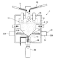
図1は、本発明の一実施形態に係るガラス溶融炉の一例の概略を示す図であって、符号1はガラス溶融炉を示している。
ガラス溶融炉1は、例えば、ガラスビーズを原料として溶融ガラスGを生成し、この溶融ガラスGに放射性廃液を混合してガラス固化体とする放射性廃液物再処理用のガラス溶解炉とされている。
The glass melting furnace according to the present invention will be described below with reference to FIGS.
FIG. 1 is a diagram showing an outline of an example of a glass melting furnace according to an embodiment of the present invention, and reference numeral 1 indicates a glass melting furnace.
The glass melting furnace 1 is, for example, a glass melting furnace for reprocessing radioactive waste liquid that produces a molten glass G using glass beads as a raw material and mixes the molten glass G with a radioactive waste liquid to obtain a solidified glass. .
ガラス溶融炉1は、溶融炉本体10と、原料供給管13と、排液供給管14と、間接加熱ヒータ15と、主電極16と、補助電極17と、底部電極18と、流下ノズル19と、堆積物検出装置(堆積物検出手段)20とを備えている。また、流下ノズル19の下方にはキャニスタ−50が配置可能とされ、溶融炉本体10内で溶融ガラスGを直接通電して加熱するとともに流下ノズル19から溶融ガラスGを排出してキャニスタ−50に充填するようになっている。
The glass melting furnace 1 includes a
溶融炉本体10は、耐火煉瓦により形成され内方が溶融ガラスGを貯留するための溶融空間11とされており、溶融空間11は、上方が略直方体状に形成されるとともに下部が上方から下方に向かうに従って断面積が縮小するいわゆる逆ピラミッドの四角錐状空間とされていて、この四角錐状空間は、溶融ガラスGを流下ノズル19にスムースに流動させるための導出部11Aとされている。
The melting furnace
溶融炉本体10を構成する耐火煉瓦は、例えば、Al2O3+Cr2O3により形成されており、耐火煉瓦と耐火煉瓦とはその間にホウ珪酸ガラスを充填することにより接合されており、電気的に充分な絶縁性を有するとともに電磁波が透過可能とされている。
The refractory brick constituting the melting furnace
原料供給管13は、ガラス溶融炉1の上部に配置されていて、溶融空間11に溶融ガラスGの原料となるガラスビーズを投入するようになっている。
排液供給管14は、ガラス溶融炉1の上部に配置されていて、例えば、核燃料製造施設において核燃料生成の際に排出される放射性廃液を溶融空間11に投入するものであり、放射性廃液には高濃度の白金族類元素(ロジウム、パラジウム、ルテニウム)が含有されている。
The raw
The
間接加熱ヒータ15は、溶融空間の上部に配置され、例えば、ニクロム線等の電気抵抗体により構成されており通電されることにより加熱して溶融空間11内に充填されたガラスビーズを輻射熱で加熱、溶融するとともに溶融された溶融ガラスGの温度を維持又は昇温するようになっている。
The
主電極16は、例えば、耐熱性と溶融ガラスGに対する耐腐食性を有するインコネルにより形成された一対の電極部材から構成され、例えば溶融空間中間部に対向して配置されるとともに溶融空間11側の端部が導出部11A内に露出して形成され、溶融空間11の溶融ガラスGに直接通電してジュール熱を発生させ、溶融ガラスGを昇温するとともにガラスビーズを溶融ガラスGに溶解するようになっている。
The
補助電極17は、例えば、主電極16と同様にインコネルにより形成された一対の電極部材から構成され、例えば導出部11Aの高さ方向の中間に主電極と直交する方向に対向して配置されるとともに溶融空間11側の端部が導出部11Aに露出して形成されている。かかる構成とすることにより、主電極16で加熱が充分に行なえない導出部11A内の溶融ガラスGを充分に加熱することができる。なお、図1においては、便宜のため主電極と同方向に図示している。
また、補助電極17には通気路が形成されていて、矢印に沿って冷却空気を流通させることにより補助電極17の温度上昇を抑制することができるようになっている。
The
Further, the
底部電極18は、例えば、主電極16と同様にインコネルにより形成された一つの電極部材により形成され、導出部11Aの中央部に形成された開口部に上方を導出部11Aに露出して配置されている。
また、底部電極18は平面視して中央部に形成された流路を流下ノズル19の流路と連通されており溶融ガラスGを流下ノズル19に流通させることができるようになっている。
また、底部電極18には通気路が形成されていて、矢印に沿って冷却空気を流通させることにより底部電極18の温度上昇を抑制することができるようになっている。
The
In addition, the
Further, a ventilation path is formed in the
主電極16、補助電極17、底部電極18は、上方からこの順番に配置されており、それぞれの電極部材に印加する電圧の設定により、主電極16を構成する電極部材の間、補助電極17を構成する電極部材の間、主電極16と補助電極17の間、主電極16と底部電極18の間、補助電極17と底部電極18の間で溶融ガラスGに通電してジュール熱を発生させて溶融ガラスGを加熱するようになっている。
なお、この実施形態において、溶融ガラスGに通電する電流は交流電流とされている。
The
In this embodiment, the current that flows through the molten glass G is an alternating current.
流下ノズル19は、溶融空間11の下部に配置され、導出部11Aに連通して形成されるとともに溶融ガラスGを排出してキャニスタ−50に充填するようになっている。
なお、流下ノズル19は、高周波誘導加熱コイルが流路を取り囲むようにして形成されており、流下ノズル壁を誘導加熱することにより流路内を通過する溶融ガラスGの温度を調整可能とされている。
The flow-down
The falling
ガラス溶融炉1は、かかる構成により投入されたガラスビーズを初期段階は間接加熱ヒータ15で加熱、溶融して溶融ガラスGとし、その後、主電極16、補助電極17、底部電極18のいずれかに電圧を印加して溶融ガラスGに通電して加熱、溶融するようになっている。
The glass melting furnace 1 heats and melts the glass beads introduced by such a configuration with the
また、溶融空間11内の溶融ガラスGにガラスビーズ及び放射性排液を投入して溶融するとともに溶融ガラスGに放射性廃液を混合し、放射性排液が混合された溶融ガラスGを流下ノズル排出してキャニスタ−50内に充填して固化するようになっている。
Further, glass beads and radioactive drainage are introduced into the molten glass G in the
堆積物検出装置20は、図2に示すように照射アンテナ(照射部)21と、受信アンテナ(受信部)23と、温度センサ24と、検出部25と、信号処理部30と、表示部40とを備えており、照射アンテナ21が照射した電磁波を受信アンテナ23で受信し、電磁波が照射されてから受信されるまでの時間ΔT及び信号強度に基づいて溶融空間11内の堆積物を検出し堆積物の分布をCRT(濃度分布表示手段)等の表示部40に表示するようになっている。なお、演算部33とデータベース34Aは、濃度算出手段を構成している。
As shown in FIG. 2, the
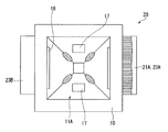
照射アンテナ21は、堆積物の検出に必要な分解能の約2倍以下の波長の電磁波(例えば、ミリ波又はマイクロ波)を照射するように構成されており、この実施形態における照射アンテナ21は、図3、図4に示すように導出部11A側に向かって延在する複数のアンテナエレメント群から構成され、多点計測が可能な多点式のアンテナとされている。具体的には複数のアンテナエレメントがその延在する方向と直交する面においてマトリックス状に配置されており、このマトリックスは四角錐状の溶融空間11の稜線をカバーするようになっている。なお、図3において斜線を付した部分は、導出部11Aの稜線部に堆積した堆積物を概念的に示している。
The
また、照射アンテナ21、受信アンテナ23は、耐火煉瓦の炉壁の外に配置されていることが望ましいが、目的物である高濃度の白金族類含有ガラス等の堆積物に信号が到達するまでの電磁波の減衰、散乱を考慮して炉壁に埋め込み堆積物に近づけてもよい。
The
また、照射アンテナ21を構成するそれぞれのアンテナエレメントは、マトリックスの配列に従って検出部25から順番に給電可能とされており、電磁波を順次照射するようになっている。なお、電磁波の照射順序については、受信した電磁波とマトリックス配列と対応できれば任意に設定してもよい。
In addition, each antenna element constituting the
受信アンテナ(受信部)23は、堆積物等において反射する反射波を受信する反射波アンテナ23Aと、導出部11Aを透過した電磁波を受信する透過波アンテナ23Bとを備えており、この実施形態において反射波アンテナ23Aは照射アンテナ21と同じ側に配置されている。
The reception antenna (reception unit) 23 includes a reflected
温度センサ24は、照射アンテナ21のマトリックスに対応して複数配置されており、配置する位置は温度センサ24で測定した溶融ガラスGの温度と受信アンテナ23で受信した電磁波の信号強度とともに白金族類濃度を算出した場合に、その誤差が許容範囲内になるように構成されている。
A plurality of
検出部25は、照射回路26、反射波受信回路27、透過波受信回路28、温度検出回路29を備え、照射回路26、反射波受信回路27、透過波受信回路28は、それぞれ照射アンテナ21、反射波アンテナ23A、透過波アンテナ23Bに接続され、温度検出回路29は温度センサ24に接続されている。
The
照射回路26は、照射アンテナ21のそれぞれのアンテナエレメントとスイッチング回路を介して接続されており、信号処理部30の出力部35からの出力信号によって対象となるアンテナエレメントに給電して電磁波を出力するように構成されている。
The
反射波受信回路27は、反射波アンテナ23Aが受信した反射波を電圧信号に変換して反射波信号として信号処理部30に出力するように構成されている。
また、透過波受信回路28は、透過波アンテナ23Bが受信した透過波を電圧信号に変換して透過波信号として信号処理部30に出力するように構成されている。
また、温度検出回路29は温度センサ24が検出した温度測定信号を信号処理部30に出力するようになっている。
The reflected
The transmitted
In addition, the
信号処理部30は、図2に示すように、入力部(入力手段)31と、メモリ32と、演算部33と、ハードディスク装置34と、出力部35と、これら相互のデータ等を通信するための通信線37とを備え、ハードディスク装置34にはデータベース34Aが格納されている。
As shown in FIG. 2, the
入力部31は、例えば、図示しないキーボード等のデータ入力機器を有して演算部33に設定等を出力するとともに、反射波受信回路27、透過波受信回路28、温度検出回路29に接続され、これらが出力した反射波信号、透過波信号、及び温度測定信号を演算部33に出力するようになっている。
The
演算部33は、例えば、メモリ32のROMに格納されたプログラムを読み込んでプログラムを実行することにより、電磁波を照射する対象のアンテナエレメントに出力部35を介して順次給電する指示を照射回路26に出力し、入力部31から入力された反射波信号、透過波信号、及び温度測定信号をデータベース34Aを参照し、マトリックスのアンテナエレメントに対応する位置の白金族類濃度wを算出し、算出した白金族類濃度wをマトリックスに対応させてメモリ32に格納するようになっている。また、メモリ32に格納した白金族類濃度wをマトリックスに対応させて出力部35に出力するようになっている。
この実施形態において、算出した白金族類濃度wは閾値に基づいて二値化するようになっている。なお、二値化に代えて、白金族類濃度wを量子化して濃淡により表示してもよい。
For example, the
In this embodiment, the calculated platinum group concentration w is binarized based on a threshold value. In place of binarization, the platinum group concentration w may be quantized and displayed by shading.
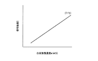
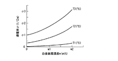
データベース34Aは、例えば、図5に示すような白金族類濃度w(wt%)と受信アンテナ23から入力される信号強度Sとの相関を、溶融ガラス温度T1をパラメータとして表示したグラフを数値テーブル化して構成されており、演算部33が信号強度S及び溶融ガラスGの温度T1を参照して白金族類濃度(wt%)を算出可能とされている。
The database 34A is, for example, a numerical table in which the correlation between the platinum group concentration w (wt%) and the signal intensity S input from the receiving
また、データベース34Aは、図6に示すような白金族類濃度w(wt%)と導電率σ(1/Ωm)とが溶融ガラス温度(T1、T2、T3)をパラメータとして一定の相関関係を有することに基づいている。
なお、図6に示すグラフに代えて、誘電率、誘電損失が溶融ガラスGの温度によって変化することに基づき、これらと信号強度Sとの相関に基づいて白金族類濃度(wt%)を算出するデータベースを構成してもよい。
Further, the database 34A shows that the platinum group concentration w (wt%) and the electrical conductivity σ (1 / Ωm) as shown in FIG. 6 have a certain correlation with the molten glass temperature (T1, T2, T3) as a parameter. Based on having.
In place of the graph shown in FIG. 6, the platinum group concentration (wt%) is calculated based on the correlation between the dielectric constant and the dielectric loss depending on the temperature of the molten glass G and the signal intensity S. A database may be configured.
次に、図7を参照して、信号処理部30が白金族類濃度wをマトリックスに対応させて表示する手順について説明する。
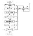
図7は、導出部11Aにおける白金族類濃度をマトリックスに従ってマッピングするためのプログラムの一例を示すフロー図である。
Next, with reference to FIG. 7, the procedure in which the
FIG. 7 is a flowchart showing an example of a program for mapping the platinum group concentration in the
1)まず、演算部33は、照射対象のアンテナエレメントを選択する。(S1)
2)次に、演算部33は、照射回路に電磁波を照射する指示をする。(S2)
この指示によって、照射回路26の照射対象となるアンテナエレメントのスイッチング回路がONになりアンテナエレメントから電磁波が照射される。
3)電磁波が照射されたら、反射波受信アンテナ23A及び透過波受信アンテナ23Bが電磁波を受信し、受信した反射波信号及び透過波信号は、反射波受信回路27及び透過波受信回路を介して入力部31に入力される。
また、マトリックス上の対応する位置(領域)の温度センサ24が検出した温度測定信号が温度検出回路29を介して入力部31に入力される。
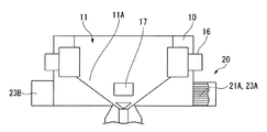
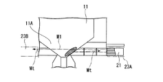
図8は、照射アンテナ21による電磁波の照射、受信アンテナ23による電磁波の受信の一例を示す概念図であり、符号M1は照射した電磁波を、符号Mrは反射した電磁波を、符号Mtは透過波を示している。なお、図8において斜線を付した部分は、導出部11Aに堆積した堆積物を示している。
4)演算部33は、反射波受信回路27及び透過波受信回路を介して取得した反射波信号及び透過波信号をメモリ32に格納された基準データと比較し、比較した結果が許容範囲内で正常時との変化(差異)がない場合にはS8に移行し、比較結果が許容範囲を超えていて正常時に対して変化がある場合にはS5に移行する。(S4)
5)S8に移行した場合には照射するアンテナエレメントを変更する。(S8)
アンテナエレメントを変更したら照射対象のアンテナエレメントを選択(S1)する。
6)S5に移行した場合には、演算部33は入力部31から取得した反射波信号及び透過波信号の信号強度S、温度測定信号をデータベース34Aを参照してマトリックスの対応する位置の白金族類濃度w(wt%)を算出する。(S5)
なお、反射波が戻る時間Δtに基づいて堆積物までの距離を算出して堆積物の厚さを特定してもよい。
7)演算部33は、マトリックス上の位置と白金族類濃度w(wt%)を対応させてメモリ32に格納する。
8)マトリックス上のすべての位置に対する照射が終了している場合には、マッピングが完了したものと判断してプログラムを終了し、マトリックス上に電磁波を照射していない位置がある場合にはマトリックス上の残余の位置における堆積物の堆積状況を把握するために照射アンテナエレメントを変更するためにS8に移行する。(S7)
9)演算部33は、マトリックス上のすべての位置に対する電磁波の照射が完了するまでプログラムを繰り返し実行する。
10)演算部33は、プログラムの実行を終了したら、メモリ32のデータに基づいて出力部35を介して表示部40に出力して、白金族類濃度w(wt%)の濃度分布を2値(例えば、白黒)表示して可視化する。
1) First, the
2) Next, the
By this instruction, the switching circuit of the antenna element to be irradiated by the
3) When the electromagnetic wave is irradiated, the reflected
Further, a temperature measurement signal detected by the
FIG. 8 is a conceptual diagram showing an example of irradiation of electromagnetic waves by the
4) The
5) When the process proceeds to S8, the antenna element to be irradiated is changed. (S8)
When the antenna element is changed, the antenna element to be irradiated is selected (S1).
6) When the process proceeds to S5, the
The thickness of the deposit may be specified by calculating the distance to the deposit based on the return time Δt of the reflected wave.
7) The
8) When irradiation is completed for all positions on the matrix, it is determined that mapping has been completed, and the program is terminated. If there are positions on the matrix that are not irradiated with electromagnetic waves, The process proceeds to S8 in order to change the irradiation antenna element in order to grasp the deposition state of the deposit at the remaining positions. (S7)
9) The
10) After completing the execution of the program, the
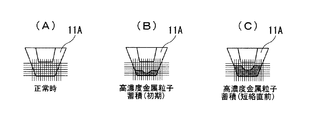
図9は、検出した白金族類濃度w(wt%)をCRT等の表示部40に表示した場合の一例を示す図であり、網かけ部分は堆積物が閾値以上であることを示している。
図9(A)は、堆積物が堆積していない正常時のマトリックスを、(B)は高濃度金属粒子が蓄積する初期を、(C)は堆積物が堆積して高濃度に蓄積されていてメンテナンスが必要とされる短絡直前の状態を示している。
FIG. 9 is a diagram showing an example when the detected platinum group concentration w (wt%) is displayed on the
9A shows a normal matrix in which no deposit is deposited, FIG. 9B shows an initial stage in which high-concentration metal particles accumulate, and FIG. 9C shows a deposit deposited and accumulated in a high concentration. This shows the state just before a short circuit that requires maintenance.
ガラス溶融炉1によれば、照射アンテナ21が、溶融空間11の導出部において堆積物が堆積しやすい稜線を含む領域をカバーしているので堆積物の堆積を効率的に把握することができる。
According to the glass melting furnace 1, the
また、ガラス溶融炉1によれば、堆積物の濃度分布を可視化できるので、例えば、堆積物の濃度分布に偏りが生じて堆積物が部分的な凸部を有して堆積した場合でも効率的に把握することができる。また、堆積物の濃度を把握することで堆積物による影響の程度を把握することができる。 Further, according to the glass melting furnace 1, the concentration distribution of the deposit can be visualized, so that, for example, even when the concentration distribution of the deposit is uneven and the deposit is deposited with partial protrusions, it is efficient. Can grasp. In addition, by grasping the concentration of the deposit, the degree of influence by the deposit can be grasped.
ガラス溶融炉1によれば、白金族類濃度w(wt%)を効率的に算出することができる。
また、受信した電磁波の信号強度Sと、溶融ガラスGの温度T1とをデータベース34Aに参照して算出するので白金族類濃度w(wt%)を容易に算出することができる。
According to the glass melting furnace 1, the platinum group concentration w (wt%) can be efficiently calculated.
Further, since the signal intensity S of the received electromagnetic wave and the temperature T1 of the molten glass G are calculated with reference to the database 34A, the platinum group concentration w (wt%) can be easily calculated.
また、ガラス溶融炉1の運転開始時の正常な状態から炉内状況を監視して高濃度白金族類が通電電極間にまたがって堆積する状態となった場合に回復操作(堆種物除去や洗浄運転など)を効率的に行うことができる。 In addition, the normal condition at the start of the operation of the glass melting furnace 1 is monitored, and when the high concentration platinum group is deposited across the energized electrodes, the recovery operation (e.g. removal of deposits and Cleaning operation) can be performed efficiently.
また、図9に示すように白金族類濃度w(wt%)の分布を表示して可視化することができるので、白金族類の堆積状況を効率的かつ的確に把握して、ガラス溶融炉1を効率的に操業して運転コスト及びメンテナンスコストを削減することができる。
また、流下ノズル19に電磁波を照射した場合、流下する溶融ガラスGの白金族類濃度wをガラス溶融炉を運転しながら効率的に把握することができる。
Further, as shown in FIG. 9, since the distribution of platinum group concentration w (wt%) can be displayed and visualized, the deposition status of the platinum group can be grasped efficiently and accurately, and the glass melting furnace 1 Can be operated efficiently to reduce operating costs and maintenance costs.
In addition, when the falling
また、最適な運転条件を決めるためのモックアップ試験では、通電電流量や温度分布と白金族類堆積との相関をとることで、効率よく最適な運転条件を確立することができる。 Also, in the mock-up test for determining the optimum operating conditions, the optimum operating conditions can be established efficiently by correlating the amount of energized current and temperature distribution with the platinum group deposition.
なお、この発明は上記実施の形態に限定されるものではなく、発明の趣旨を逸脱しない範囲において、種々の変更をすることが可能である。
例えば、上記実施の形態においては、堆積物がガラス溶融炉内に堆積する白金族類を含有する溶融ガラスGによる場合について説明したが、電磁波の反射、透過、吸収特性が異なる物質であれば、他の堆積物を対象として本発明を適用してもよい。
Note that the present invention is not limited to the above-described embodiment, and various modifications can be made without departing from the spirit of the invention.
For example, in the above embodiment, the case where the deposit is a molten glass G containing a platinum group deposited in a glass melting furnace has been described. However, if the substance has different electromagnetic wave reflection, transmission, and absorption characteristics, The present invention may be applied to other deposits.
また、ガラス溶融炉1が溶融ガラスGと白金族類を含有する放射性廃液とを混合する場合について説明したが、例えば、溶融ガラスGと、溶融ガラスGと混合した場合に電磁波による検出が可能な白金族類以外の物質を溶融ガラスGと混合する場合にも適用することもできる。 Moreover, although the case where the glass melting furnace 1 mixes the molten glass G and the radioactive waste liquid containing platinum group was demonstrated, for example, when mixed with the molten glass G and the molten glass G, detection by electromagnetic waves is possible. The present invention can also be applied when a substance other than the platinum group is mixed with the molten glass G.
また、上記実施の形態においては、検出した受信波を信号処理部30で可視化する場合について説明したが、例えば、反射波の信号レベルが所定値以上であることを以って堆積物の堆積を把握するだけの構成としてもよい。
In the above embodiment, the case where the detected received wave is visualized by the
また、上記実施の形態においては、堆積物の堆積状況をデータベース34Aに格納されたデータと照合して算出する場合について説明したが、予め堆積状況と反射波の相関関係から求めた回帰式等により算出する構成としてもよい。 Further, in the above-described embodiment, the case where the accumulation state of the deposit is calculated by collating with the data stored in the database 34A has been described. However, the regression equation obtained from the correlation between the accumulation state and the reflected wave in advance is used. It is good also as a structure to calculate.
また、マトリックス状に配置したアンテナエレメント群に代えて溶融空間11に対して電磁波を走査して照射することにより白金族類濃度wの分布状態を表示するようにしてもよい。
Alternatively, the distribution state of the platinum group concentration w may be displayed by scanning and irradiating electromagnetic waves to the
また、上記実施の形態においては、受信アンテナ23が反射波受信アンテナ23Aと、透過波受信アンテナ23Bとを備える場合について説明したが、受信アンテナ23を反射波アンテナ23Aと透過波アンテナ23Bのいずれか一方により構成してもよい。
In the above embodiment, the case where the receiving
また、上記実施の形態においては、照射アンテナ21及び反射波アンテナ23A、透過波アンテナ23Bをガラス溶融炉本体10の側方に配置する場合について説明したが、これらの配置する位置をガラス溶融炉本体10の上方や下方としてもよい。
また、上記実施の形態においては、溶融空間11の下部が上方から下方に向かうに従って断面積が縮小する四角錐状空間である場合について説明したが、例えば、三角錐、五角錐等の多角錘の他、円錐に形成されていてもよい。
Moreover, in the said embodiment, although the case where the
In the above embodiment, the case where the lower part of the
上記実施の形態においては、反射波の戻ってくる時間ΔT、信号強度Sから堆積物の位置や濃度を算出する場合について説明したが、反射波、透過波、これらを比較することにより取得可能な信号から、堆積物に関する濃度以外の物理量を取得する構成としてもよい。 In the above embodiment, the case where the position and concentration of the deposit is calculated from the return time ΔT and the signal intensity S of the reflected wave has been described, but the reflected wave, the transmitted wave, and these can be obtained by comparing them. It is good also as a structure which acquires physical quantities other than the density | concentration regarding a deposit from a signal.
また、上記実施の形態においては、マトリックス状に配置されたアンテナエレメント群を用いて堆積物を検出する場合について説明したが、電磁波の照射対象を、一点とするか、多点とするか、所定の面積を有する範囲とするかについては任意に設定可能である。また、走査式の単体アンテナを用いてもよい。 In the above embodiment, the case where the deposit is detected using the antenna element group arranged in a matrix has been described. However, the electromagnetic wave irradiation target may be one point, multiple points, or a predetermined number. It can be arbitrarily set as to whether or not it is a range having the area. A scanning single antenna may also be used.
また、上記実施の形態においては、突出して形成された複数のアンテナエレメントがマトリックス状に配置された照射アンテナ21を用いる場合について説明したが、例えば、ホーンアンテナ等の他の種類のアンテナを用いてもよい。
Further, in the above embodiment, the case where the
上記実施の形態においては、耐火煉瓦がAl2O3+Cr2O3により形成され、耐火煉瓦と耐火煉瓦との間にホウ珪酸ガラスからなる接合材が充填されている場合について説明したが、耐火煉瓦及び接合材については耐熱性、電気絶縁性を有し電磁波が通過な物質であれば上記以外の物質を用いてもよい。 In the above-described embodiment, the refractory bricks are formed by Al 2 O 3 + Cr 2 O 3, but the bonding material made of borosilicate glass case has been described which is filled between the refractory bricks and the refractory bricks, refractory As for the brick and the bonding material, materials other than those described above may be used as long as the materials have heat resistance and electrical insulation and can pass electromagnetic waves.
また、上記実施の形態においては、ガラス溶融炉1が、一対の主電極16と、一対の補助電極17と、一つの底部電極18を備えた場合について説明したが、例えば、主電極16のみを備えた構成、主電極16と補助電極17のみを備えた構成等、電極の構成については任意に設定可能である。
また、電極間に流す電流に関しては、交流電流、直流電流のいずれを流す構成としてもよい。
Moreover, in the said embodiment, although the glass melting furnace 1 demonstrated the case where it provided with a pair of
Further, regarding the current flowing between the electrodes, either an alternating current or a direct current may be passed.
G 溶融ガラスG
1 ガラス溶融炉
10 溶融炉本体
11 溶融空間
11A 導出部
16 主電極
17 補助電極
18 底部電極
20 堆積物検出装置
21 照射アンテナ(照射部)
23 受信アンテナ(受信部)
23A 反射波受信アンテナ(受信部)
23B 透過波受信アンテナ(受信部)
24 温度センサ
25 検出部
30 信号処理部
31 入力部
33 演算部
34A データベース
35 出力部
40 表示部
G Molten glass G
DESCRIPTION OF SYMBOLS 1
23 Reception antenna (receiver)
23A Reflected wave receiving antenna (receiver)
23B Transmitted wave receiving antenna (receiver)
24
Claims (3)
前記溶融空間に電磁波を照射可能とされる照射部と、
前記照射部が照射した電磁波を受信する受信部と、
前記照射部に給電するとともに前記受信部が受信した電磁波を検出する検出部と、を有し、
前記照射部から照射した電磁波を前記受信部で受信し、前記検出部で前記受信した電磁波に基づいて前記溶融空間の堆積物を検出する堆積物検出手段を備えることを特徴とするガラス溶融炉。 A glass melting furnace configured to store molten glass in a molten space formed of refractory bricks, and to discharge the stored molten glass from a flow nozzle connected to a lead-out portion below the molten space. And
An irradiating part capable of irradiating the molten space with electromagnetic waves;
A receiving unit that receives the electromagnetic waves irradiated by the irradiation unit;
A detector that feeds power to the irradiator and detects the electromagnetic waves received by the receiver,
A glass melting furnace comprising deposit detection means for receiving electromagnetic waves emitted from the irradiation unit by the receiving unit and detecting deposits in the melting space based on the received electromagnetic waves by the detection unit.
前記照射部は、前記溶融空間の側方に配置され、
前記受信部は、
前記溶融空間に対して前記照射部と同じ側と反対側の少なくともいずれかの側方に配置されることを特徴とするガラス溶融炉。 The glass melting furnace according to claim 1,
The irradiation unit is disposed on the side of the melting space,
The receiver is
A glass melting furnace, which is arranged on at least one side opposite to the same side as the irradiation unit with respect to the melting space.
前記溶融空間に照射部から電磁波を送信する工程と、
前記照射された電磁波を受信部で受信する工程と、
該受信した電磁波を検出部で信号に変換して前記堆積物を検出する工程と、を備えることを特徴とする堆積物検出方法。 Deposition in a glass melting furnace configured to store molten glass in a molten space formed of refractory bricks and to discharge the stored molten glass from a flow nozzle connected to a lead-out portion below the molten space An object detection method comprising:
Transmitting electromagnetic waves from the irradiation section to the melting space;
Receiving the irradiated electromagnetic wave at a receiving unit;
And a step of detecting the deposit by converting the received electromagnetic wave into a signal by a detection unit.
Priority Applications (1)
| Application Number | Priority Date | Filing Date | Title |
|---|---|---|---|
| JP2008321289A JP2010143780A (en) | 2008-12-17 | 2008-12-17 | Glass melting furnace and method for detecting deposit |
Applications Claiming Priority (1)
| Application Number | Priority Date | Filing Date | Title |
|---|---|---|---|
| JP2008321289A JP2010143780A (en) | 2008-12-17 | 2008-12-17 | Glass melting furnace and method for detecting deposit |
Related Child Applications (1)
| Application Number | Title | Priority Date | Filing Date |
|---|---|---|---|
| JP2014101670A Division JP5765466B2 (en) | 2014-05-15 | 2014-05-15 | Glass melting furnace |
Publications (1)
| Publication Number | Publication Date |
|---|---|
| JP2010143780A true JP2010143780A (en) | 2010-07-01 |
Family
ID=42564600
Family Applications (1)
| Application Number | Title | Priority Date | Filing Date |
|---|---|---|---|
| JP2008321289A Pending JP2010143780A (en) | 2008-12-17 | 2008-12-17 | Glass melting furnace and method for detecting deposit |
Country Status (1)
| Country | Link |
|---|---|
| JP (1) | JP2010143780A (en) |
Citations (7)
| Publication number | Priority date | Publication date | Assignee | Title |
|---|---|---|---|---|
| JPS61290378A (en) * | 1985-06-17 | 1986-12-20 | Ishikawajima Harima Heavy Ind Co Ltd | Instrument for measuring deposited quantity in vertical furnace |
| JPS625210U (en) * | 1985-06-25 | 1987-01-13 | ||
| JPS6352795U (en) * | 1986-09-24 | 1988-04-09 | ||
| JP2001255137A (en) * | 2000-03-13 | 2001-09-21 | Ishikawajima Harima Heavy Ind Co Ltd | Lifetime inspecting device for glass-melting furnace |
| JP2002071891A (en) * | 2000-08-30 | 2002-03-12 | Ishikawajima Harima Heavy Ind Co Ltd | Resistance measuring instrument in glass melting furnace |
| JP2002236197A (en) * | 2001-02-08 | 2002-08-23 | Ishikawajima Harima Heavy Ind Co Ltd | Stirrer for glass fusion furnace |
| JP2005300218A (en) * | 2004-04-07 | 2005-10-27 | Jfe Engineering Kk | Method and device for detecting deposition level of charging material in high-temperature vertical reactor |
-
2008
- 2008-12-17 JP JP2008321289A patent/JP2010143780A/en active Pending
Patent Citations (7)
| Publication number | Priority date | Publication date | Assignee | Title |
|---|---|---|---|---|
| JPS61290378A (en) * | 1985-06-17 | 1986-12-20 | Ishikawajima Harima Heavy Ind Co Ltd | Instrument for measuring deposited quantity in vertical furnace |
| JPS625210U (en) * | 1985-06-25 | 1987-01-13 | ||
| JPS6352795U (en) * | 1986-09-24 | 1988-04-09 | ||
| JP2001255137A (en) * | 2000-03-13 | 2001-09-21 | Ishikawajima Harima Heavy Ind Co Ltd | Lifetime inspecting device for glass-melting furnace |
| JP2002071891A (en) * | 2000-08-30 | 2002-03-12 | Ishikawajima Harima Heavy Ind Co Ltd | Resistance measuring instrument in glass melting furnace |
| JP2002236197A (en) * | 2001-02-08 | 2002-08-23 | Ishikawajima Harima Heavy Ind Co Ltd | Stirrer for glass fusion furnace |
| JP2005300218A (en) * | 2004-04-07 | 2005-10-27 | Jfe Engineering Kk | Method and device for detecting deposition level of charging material in high-temperature vertical reactor |
Similar Documents
| Publication | Publication Date | Title |
|---|---|---|
| JP4853036B2 (en) | Induction heating device | |
| JP4691710B2 (en) | Electric melting furnace for waste vitrification | |
| CN104750140B (en) | Reaction chamber method for heating and controlling and device | |
| JP5765466B2 (en) | Glass melting furnace | |
| CN104111227A (en) | Detection apparatus and detection method for water quality in inner container of electric water heater | |
| CN109708751A (en) | Photosensitive sensor detects modification method, device and air conditioner | |
| JP2012191582A (en) | Gas cell unit, atomic oscillator and electronic apparatus | |
| CN106156421B (en) | Electronic Packaging thermal fatigue life of solder joint prediction technique based on impulse eddy current thermal imaging | |
| KR102057487B1 (en) | A directly draining type induction easy cooker | |
| JP2010143780A (en) | Glass melting furnace and method for detecting deposit | |
| JP4630976B2 (en) | Glass melting furnace | |
| CN106032932A (en) | Heating device and local flushing device using the same | |
| KR101625526B1 (en) | Electric kettle infrared light temperature sensor is provided | |
| JP2005134230A (en) | Liquid level detection device | |
| JP2007329025A (en) | Induction heating cooker | |
| US7997121B2 (en) | Milliwave melter monitoring system | |
| KR102175190B1 (en) | Apparatus for fault diagnosis of heater using power consumption and method thereof | |
| CN102681387A (en) | Image forming apparatus | |
| JP2016020851A (en) | Liquid level measuring system and liquid level measuring method | |
| CN104792862A (en) | Electric water heater, and method and apparatus for monitoring quality of water in internal container of electric water heater | |
| US20110255847A1 (en) | Rapid heat treatment apparatus that enables extended pyrometer life | |
| JP4285502B2 (en) | Induction heating cooker | |
| JP5252354B2 (en) | Scale detection sensor and scale detection method | |
| JP5855530B2 (en) | X-ray inspection equipment | |
| CN104897969A (en) | Method and device for detecting conductivity in instant electric water heater |
Legal Events
| Date | Code | Title | Description |
|---|---|---|---|
| A621 | Written request for application examination |
Effective date: 20111026 Free format text: JAPANESE INTERMEDIATE CODE: A621 |
|
| A977 | Report on retrieval |
Free format text: JAPANESE INTERMEDIATE CODE: A971007 Effective date: 20130313 |
|
| A131 | Notification of reasons for refusal |
Free format text: JAPANESE INTERMEDIATE CODE: A131 Effective date: 20130416 |
|
| A521 | Written amendment |
Free format text: JAPANESE INTERMEDIATE CODE: A523 Effective date: 20130617 |
|
| A131 | Notification of reasons for refusal |
Effective date: 20140318 Free format text: JAPANESE INTERMEDIATE CODE: A131 |
|
| A02 | Decision of refusal |
Free format text: JAPANESE INTERMEDIATE CODE: A02 Effective date: 20140708 |
