JP2010143532A - Pneumatic tire - Google Patents
Pneumatic tire Download PDFInfo
- Publication number
- JP2010143532A JP2010143532A JP2008325970A JP2008325970A JP2010143532A JP 2010143532 A JP2010143532 A JP 2010143532A JP 2008325970 A JP2008325970 A JP 2008325970A JP 2008325970 A JP2008325970 A JP 2008325970A JP 2010143532 A JP2010143532 A JP 2010143532A
- Authority
- JP
- Japan
- Prior art keywords
- zigzag
- side region
- siping
- tire
- axial direction
- Prior art date
- Legal status (The legal status is an assumption and is not a legal conclusion. Google has not performed a legal analysis and makes no representation as to the accuracy of the status listed.)
- Granted
Links
Images


Classifications
-
- B—PERFORMING OPERATIONS; TRANSPORTING
- B60—VEHICLES IN GENERAL
- B60C—VEHICLE TYRES; TYRE INFLATION; TYRE CHANGING; CONNECTING VALVES TO INFLATABLE ELASTIC BODIES IN GENERAL; DEVICES OR ARRANGEMENTS RELATED TO TYRES
- B60C11/00—Tyre tread bands; Tread patterns; Anti-skid inserts
- B60C11/03—Tread patterns
- B60C11/12—Tread patterns characterised by the use of narrow slits or incisions, e.g. sipes
- B60C11/1236—Tread patterns characterised by the use of narrow slits or incisions, e.g. sipes with special arrangements in the tread pattern
-
- B—PERFORMING OPERATIONS; TRANSPORTING
- B60—VEHICLES IN GENERAL
- B60C—VEHICLE TYRES; TYRE INFLATION; TYRE CHANGING; CONNECTING VALVES TO INFLATABLE ELASTIC BODIES IN GENERAL; DEVICES OR ARRANGEMENTS RELATED TO TYRES
- B60C11/00—Tyre tread bands; Tread patterns; Anti-skid inserts
- B60C11/03—Tread patterns
- B60C11/0304—Asymmetric patterns
-
- B—PERFORMING OPERATIONS; TRANSPORTING
- B60—VEHICLES IN GENERAL
- B60C—VEHICLE TYRES; TYRE INFLATION; TYRE CHANGING; CONNECTING VALVES TO INFLATABLE ELASTIC BODIES IN GENERAL; DEVICES OR ARRANGEMENTS RELATED TO TYRES
- B60C11/00—Tyre tread bands; Tread patterns; Anti-skid inserts
- B60C11/03—Tread patterns
- B60C11/12—Tread patterns characterised by the use of narrow slits or incisions, e.g. sipes
- B60C11/1204—Tread patterns characterised by the use of narrow slits or incisions, e.g. sipes with special shape of the sipe
- B60C2011/1213—Tread patterns characterised by the use of narrow slits or incisions, e.g. sipes with special shape of the sipe sinusoidal or zigzag at the tread surface
-
- B—PERFORMING OPERATIONS; TRANSPORTING
- B60—VEHICLES IN GENERAL
- B60C—VEHICLE TYRES; TYRE INFLATION; TYRE CHANGING; CONNECTING VALVES TO INFLATABLE ELASTIC BODIES IN GENERAL; DEVICES OR ARRANGEMENTS RELATED TO TYRES
- B60C11/00—Tyre tread bands; Tread patterns; Anti-skid inserts
- B60C11/03—Tread patterns
- B60C11/12—Tread patterns characterised by the use of narrow slits or incisions, e.g. sipes
- B60C11/1204—Tread patterns characterised by the use of narrow slits or incisions, e.g. sipes with special shape of the sipe
- B60C2011/1227—Tread patterns characterised by the use of narrow slits or incisions, e.g. sipes with special shape of the sipe having different shape within the pattern
-
- B—PERFORMING OPERATIONS; TRANSPORTING
- B60—VEHICLES IN GENERAL
- B60C—VEHICLE TYRES; TYRE INFLATION; TYRE CHANGING; CONNECTING VALVES TO INFLATABLE ELASTIC BODIES IN GENERAL; DEVICES OR ARRANGEMENTS RELATED TO TYRES
- B60C11/00—Tyre tread bands; Tread patterns; Anti-skid inserts
- B60C11/03—Tread patterns
- B60C11/12—Tread patterns characterised by the use of narrow slits or incisions, e.g. sipes
- B60C11/1272—Width of the sipe
- B60C2011/1286—Width of the sipe being different from sipe to sipe
Landscapes
- Engineering & Computer Science (AREA)
- Mechanical Engineering (AREA)
- Tires In General (AREA)
Abstract
【課題】雪上性能の低下を最小限に抑制しつつ、ドライ路面での操縦安定性を向上した空気入りタイヤを提供する。
【解決手段】ラウンドショルダのタイヤであって、トレッド部2が、縦主溝3と横溝4とによりブロック5に区分され、かつブロック5にジグザグ部8を有するサイピング6が形成される。トレッド部2を、タイヤ軸方向最外側の外の縦主溝3oによりショルダー側領域Yshと、クラウン側領域Ycrとに区分したとき、ショルダー側領域に配されるサイピング6のジグザグ部8におけるジグザグの振幅およびジグザグのピッチは、クラウン側領域Ycrに配されるサイピング6におけるジグザグの振幅およびジグザグのピッチよりも大である。前記ショルダー側領域に配されるサイピング6のタイヤ軸方向に対する角度は、Ycrに配されるサイピング6の角度よりも小である。
【選択図】図2The present invention provides a pneumatic tire with improved maneuvering stability on a dry road surface while suppressing a decrease in performance on snow.
In a tire of a round shoulder, a tread portion is divided into blocks by a longitudinal main groove and a lateral groove, and a siping having a zigzag portion is formed in the block. When the tread portion 2 is divided into the shoulder side region Ysh and the crown side region Ycr by the longitudinal main groove 3o outside the outermost side in the tire axial direction, the zigzag of the zigzag portion 8 of the siping 6 disposed in the shoulder side region The amplitude and the zigzag pitch are larger than the zigzag amplitude and the zigzag pitch in the siping 6 disposed in the crown side region Ycr. The angle of the siping 6 disposed in the shoulder side region with respect to the tire axial direction is smaller than the angle of the siping 6 disposed in Ycr.
[Selection] Figure 2
Description
本発明は、スタッドレスタイヤとして好適であり、雪上性能の低下を最小限に抑制しつつ、ドライ路面での操縦安定性を向上させた空気入りタイヤに関する。 The present invention relates to a pneumatic tire that is suitable as a studless tire and has improved steering stability on a dry road surface while minimizing a decrease in performance on snow.
氷雪路の走行に適した例えばスタッドレスタイヤ等の空気入りタイヤでは、通常、タイヤ周方向にのびる縦主溝及びこれに交わる向きの横溝により、トレッド部を複数のブロックに区分するとともに、各ブロックに複数のジグザグ状のサイピングを形成している。そして、溝内に形成される雪柱による剪断力、及び前記ブロックやサイピングのエッジによるエッジ効果などにより、雪上性能の確保が図られている。 For pneumatic tires such as studless tires suitable for running on snowy and snowy roads, the tread part is usually divided into a plurality of blocks by longitudinal main grooves extending in the tire circumferential direction and transverse grooves extending in the circumferential direction. A plurality of zigzag sipings are formed. And the performance on snow is ensured by the shearing force by the snow column formed in the groove and the edge effect by the edge of the block or siping.
そしてこの雪上性能に対して、溝容積を増し雪柱剪断力を高めること、およびサイピングの形成数を増しエッジ成分を高めることが好ましいことが知られている。 It is known that it is preferable to increase the groove volume and increase the snow column shear force, and increase the number of sipings and increase the edge component for this on-snow performance.
しかしこのような溝容積の増加やサイピングの形成数の増加は、ブロック剛性の低下を招き、ドライ路面における操縦安定性(ドライ操縦安定性という場合がある)を低下させるなど、雪上性能とドライ操縦安定性とは二律背反の関係があり、双方を高い次元で両立されることは難しい問題であった。 However, such an increase in groove volume and an increase in the number of siping formations lead to a decrease in block rigidity and a decrease in steering stability on the dry road surface (sometimes referred to as dry steering stability). There is a trade-off between stability and it was a difficult problem to achieve both at a high level.
そこで本発明者は、サイピングにおけるジグザグの振幅及びピッチに着目して研究を行った。その結果、
(1)ジグザグの振幅及びピッチが大きい場合、ジグザグの噛み合わせが強固となってブロック剛性が相対的に高まり、逆に振幅及びピッチが小さいとブロック剛性が緩和されること:及び
(2)図7に示すように、トレッド部aを、タイヤ軸方向最外側に配される外の縦主溝b、bによって、ショルダー側領域a1とクラウン側領域a2とに区分したとき、雪上走行においては、接地面積が大きいクラウン側領域a2の影響が大きく、逆に旋回時には、タイヤ軸方向の横力が強く作用するショルダー側領域a1の影響が大きいこと:が判明した。図中の符号f1は、雪上走行時の接地面形状を示し、符号f2は、ドライ路面での旋回時の接地面形状を示す。
Therefore, the present inventor conducted research while paying attention to the zigzag amplitude and pitch in siping. as a result,
(1) When the zigzag amplitude and pitch are large, the zigzag engagement is strong and the block rigidity is relatively increased. Conversely, when the amplitude and pitch are small, the block rigidity is relieved: and (2) 7, when the tread portion a is divided into the shoulder side region a1 and the crown side region a2 by the outer longitudinal main grooves b, b arranged on the outermost side in the tire axial direction, in running on snow, It was found that the crown side region a2 having a large ground contact area has a large influence, and conversely, when turning, the shoulder side region a1 to which a lateral force in the tire axial direction acts strongly has a large effect. Reference numeral f1 in the figure indicates the shape of the ground contact surface when traveling on snow, and reference symbol f2 indicates the shape of the ground contact surface during turning on a dry road surface.
そして、雪上走行への影響が大きいクラウン側領域a2において、ジグザグの振幅及びピッチが小さいサイピングを使用し、かつ旋回時への影響が大きいショルダー側領域a1において、ジグザグの振幅及びピッチが大なサイピングを使用することで、タイヤ全体として、雪噛み性や排雪性をより有効に機能させつつ、旋回時やレーンチェンジ時に作用する横力に対して、抗力を効果的に高めることが可能となり、雪上性能の低下を最小限に抑制しつつ、ドライ路面での操縦安定性を向上させうることを究明し得た。 In the crown side region a2, which has a large influence on running on snow, a siping having a small zigzag amplitude and pitch is used, and in the shoulder side region a1, which has a large influence on turning, a siping having a large zigzag amplitude and pitch is used. By using, it becomes possible to effectively increase the drag against the lateral force that acts at the time of turning or lane change, while making the snow biting property and snow drainage function more effectively as a whole tire, It has been found that it is possible to improve the handling stability on the dry road surface while minimizing the decrease in performance on snow.
本発明は、ショルダー側領域とクラウン側領域とにおいて、サイピングにおけるジグザグの振幅、ジグザグのピッチ、およびタイヤ軸方向に対するサイピングの角度を相違させることを基本として、雪上性能の低下を最小限に抑制しつつ、ドライ操縦安定性を向上させた空気入りタイヤを提供することを目的としている。
前記目的を達成するために、本願請求項1の発明は、トレッド部に、タイヤ周方向に連続してのびかつタイヤ軸方向最外側に配される一対の外の縦主溝を含む縦主溝と、この縦主溝に交わる向きの横溝とを設けることにより、前記トレッド部をブロックに区分し、かつ該ブロックにサイピングを形成した空気入りタイヤであって、
トレッド接地端を含むタイヤショルダは、タイヤ子午断面における輪郭線が曲率半径25mm以上の円弧曲線からなるラウンドショルダ形状をなし、
かつ前記サイピングは、そのサイプ長さ方向にジグザグ状にのびるジグザグ部を有し、
しかも前記外の縦主溝は、トレッド部を、該外の縦主溝よりもタイヤ軸方向外側のショルダー側領域と、外の縦主溝間のクラウン側領域とに区分するとともに、
前記サイピングのうちで、前記ショルダー側領域に配されるサイピングのジグザグ部におけるジグザグの振幅WshおよびジグザグのピッチPshは、前記クラウン側領域に配されるサイピングのジグザグ部におけるジグザグの振幅WcrおよびジグザグのピッチPcrよりも大であり、
しかも前記ショルダー側領域に配されるサイピングのタイヤ軸方向に対する角度θshは、前記クラウン側領域に配されるサイピングのタイヤ軸方向に対する角度θcrより小であることを特徴としている。
In order to achieve the above-mentioned object, the invention of
The tire shoulder including the tread contact edge has a round shoulder shape in which the contour line in the tire meridional section is an arc curve having a curvature radius of 25 mm or more,
And the siping has a zigzag portion extending zigzag in the sipe length direction,
Moreover, the outer vertical main groove divides the tread portion into a shoulder side region on the tire axial direction outer side than the outer vertical main groove and a crown side region between the outer vertical main grooves,
Among the sipings, the zigzag amplitude Wsh and zigzag pitch Psh in the zigzag portion of the siping disposed in the shoulder side region are the zigzag amplitude Wcr and zigzag pitch in the zigzag portion of the siping disposed in the crown side region. Greater than the pitch Pcr,
Moreover, the angle θsh with respect to the tire axial direction of the siping disposed in the shoulder side region is smaller than the angle θcr with respect to the tire axial direction of the siping disposed in the crown side region.
又請求項2の発明では、前記ショルダー側領域に配されるサイピングの前記ジグザグの振幅Wshと、前記クラウン側領域に配されるサイピングの前記ジグザグの振幅Wcrとの比(Wsh/Wcr)は1.2〜2.0、かつ前記ショルダー側領域に配されるサイピングのジグザグのピッチPshと、前記クラウン側領域に配されるサイピングの前記ジグザグのピッチPcrとの比(Psh/Pcr)は1.2〜3.0であることを特徴としている。
In the invention of
又請求項3の発明では、前記ショルダー側領域に配されるサイピングの前記角度θshは30°以下、前記クラウン側領域に配されるサイピングの前記角度θcrは15〜60°であることを特徴としている。
In the invention of
又請求項4の発明では、前記縦主溝は、前記クラウン側領域に配される2本以上の内の縦主溝を含み、しかも該クラウン側領域は前記内の縦主溝間の内のクラウン側領域部分と、内の縦主溝と外の縦主溝との間の外のクラウン側領域部分とに区分されるとともに、
前記内のクラウン側領域部分に配されるサイピングのタイヤ軸方向に対する傾斜の向きは、前記外のクラウン側領域部分に配されるサイピングのタイヤ軸方向に対する傾斜の向きと相違することを特徴としている。
According to a fourth aspect of the present invention, the longitudinal main groove includes two or more longitudinal main grooves arranged in the crown side region, and the crown side region is located between the longitudinal main grooves in the inside. And is divided into a crown side region portion and an outer crown side region portion between the inner vertical main groove and the outer vertical main groove,
The direction of inclination of the siping disposed in the inner crown side region portion with respect to the tire axial direction is different from the direction of inclination of the siping disposed in the outer crown side region portion with respect to the tire axial direction. .
又請求項5の発明では、前記ショルダー側領域に配されるサイピングの前記ジグザグ部は、そのジグザグ中心線のタイヤ軸方向に対する傾斜の向きが、前記ショルダー側領域に配される横溝のタイヤ軸方向に対する傾斜の向きと同方向であり、
かつ前記ジグザグ部は、前記ジグザグ中心線との交差角度が大な第1のジグザグ辺と、ジグザグ中心線との交差角度が小な第2のジグザグ辺とが交互に連なる鋸歯状をなすとともに、
前記第1のジグザグ辺のタイヤ軸方向に対する傾斜の向きは、ジグザグ中心線のタイヤ軸方向に対する傾斜の向きと相違し、第2のジグザグ辺のタイヤ軸方向に対する傾斜の向きは、ジグザグ中心線のタイヤ軸方向に対する傾斜の向きと同方向であることを特徴としている。
Further, in the invention of
And the zigzag portion has a sawtooth shape in which a first zigzag side having a large intersection angle with the zigzag centerline and a second zigzag side having a small intersection angle with the zigzag centerline are alternately connected,
The direction of inclination of the first zigzag side with respect to the tire axial direction is different from the direction of inclination of the zigzag center line with respect to the tire axial direction, and the direction of inclination of the second zigzag side with respect to the tire axial direction is different from that of the zigzag center line. It is characterized by the same direction as the direction of inclination with respect to the tire axial direction.
又請求項6の発明では、前記トレッド部は、車両装着時にタイヤ赤道よりも車両外側となる外のトレッド半部分におけるランド比Loが、車両内側となる内のトレッド半部分におけるランド比Liよりも大であることを特徴としている。 According to a sixth aspect of the present invention, the tread portion has a land ratio Lo in the outer tread half portion that is on the vehicle outer side than the tire equator when the vehicle is mounted, and a land ratio Li in the tread half portion on the vehicle inner side. It is characterized by being large.
又請求項7の発明では、前記クラウン側領域に配される横溝は、そのタイヤ軸方向両端に、前記縦主溝と交差する交差部を有するとともに、車両装着時に車両外側となる外の交差部における前記横溝の溝巾Wyoは、車両内側となる内の交差部における前記横溝の溝巾Wyiよりも小であることを特徴としている。 According to a seventh aspect of the present invention, the lateral groove disposed in the crown side region has an intersecting portion intersecting the longitudinal main groove at both ends in the tire axial direction, and an outer intersecting portion that is outside the vehicle when the vehicle is mounted. The groove width Wyo of the horizontal groove at is smaller than the groove width Wyi of the horizontal groove at the intersection inside the vehicle.
なお前記「トレッド接地端」とは、正規リムにリム組みしかつ正規内圧を充填した状態のタイヤに正規荷重を負荷してキャンバー角0°にて平坦面に接地させたときのトレッド接地面のタイヤ軸方向最外端を意味する。 The “tread grounding end” refers to a tread grounding surface when a normal load is applied to a tire that is assembled on a regular rim and filled with a regular internal pressure and is grounded on a flat surface at a camber angle of 0 °. It means the outermost end in the tire axial direction.
又前記「正規リム」とは、タイヤが基づいている規格を含む規格体系において、当該規格がタイヤ毎に定めるリムであり、例えばJATMAであれば標準リム、TRAであれば "Design Rim" 、或いはETRTOであれば "Measuring Rim"を意味する。前記「正規内圧」とは、前記規格がタイヤ毎に定めている空気圧であり、JATMAであれば最高空気圧、TRAであれば表 "TIRE LOAD LIMITS AT VARIOUS COLD INFLATION PRESSURES" に記載の最大値、ETRTOであれば "INFLATION PRESSURE"を意味するが、乗用車用タイヤの場合には180kPaとする。前記「正規荷重」とは、前記規格がタイヤ毎に定めている荷重であり、JATMAであれば最大負荷能力、TRAであれば表 "TIRE LOAD LIMITS AT VARIOUS COLD INFLATION PRESSURES" に記載の最大値、ETRTOであれば "LOAD CAPACITY"である。 The “regular rim” is a rim determined for each tire in the standard system including the standard on which the tire is based, for example, a standard rim for JATMA, “Design Rim” for TRA, or ETRTO means "Measuring Rim". The “regular internal pressure” is the air pressure defined by the standard for each tire. If JATMA, the maximum air pressure, if TRA, the maximum value described in the table “TIRE LOAD LIMITS AT VARIOUS COLD INFLATION PRESSURES” Means "INFLATION PRESSURE", but in the case of passenger car tires, it is 180 kPa. The “regular load” is a load determined by the standard for each tire. The maximum load capacity in the case of JATMA, the maximum value described in the table “TIRE LOAD LIMITS AT VARIOUS COLD INFLATION PRESSURES” in the case of TRA, If it is ETRTO, it is "LOAD CAPACITY".
ジグザグの振幅及びピッチが小なサイピングを採用することで、ブロック剛性を緩和することができ、接地する際に、ブロックに動きを持たせることができる。又ブロックに動きを持たせることで、雪上での雪噛み性や排雪性を向上させることが可能となる。そしてこの動きを持たせたブロックを、雪上走行への影響が大なクラウン側領域に配することにより、前記雪噛み性や排雪性がより有効に機能し、雪上性能を効果的に高めることができる。 By adopting siping with a small zigzag amplitude and pitch, the block rigidity can be relaxed, and the block can be moved when it comes into contact with the ground. In addition, by making the block move, it is possible to improve the snow biting property and the snow discharging property on the snow. And by placing the block with this movement in the crown side area that has a great influence on running on snow, the above-mentioned snow biting performance and snow drainage function more effectively, and the performance on snow can be effectively improved. Can do.
一方、ショルダー側領域に配されるサイピングにおいて、そのジグザグの振幅及びピッチを大とすることで、ショルダー側領域のブロック剛性を高めることができる。これにより、旋回時やレーンチェンジ時の横力に対して高い抗力を発揮させることが可能となり、前述のクラウン側領域におけるジグザグの振幅及びピッチが小なサイピングの採用と相俟って、雪上性能を高めつつドライ路面での操縦安定性を向上させることができる。 On the other hand, in siping disposed in the shoulder side region, the block rigidity of the shoulder side region can be increased by increasing the amplitude and pitch of the zigzag. This makes it possible to exert a high resistance against lateral force when turning or changing lanes, combined with the adoption of siping with small zigzag amplitude and pitch in the above-mentioned crown side region, and performance on snow. The driving stability on the dry road surface can be improved while improving
以下、本発明の実施の一形態を、図示例とともに説明する。 Hereinafter, an embodiment of the present invention will be described with reference to the drawings.
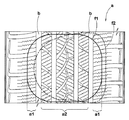
図1に、本実施形態の空気入りタイヤ1のトレッド部2の、タイヤ子午断面における輪郭線を示す。同図に示すように、前記空気入りタイヤ1は、トレッド接地端Teを含むタイヤショルダSHの輪郭線が、曲率半径Rが25mm以上の円弧曲線からなるラウンドショルダ形状のタイヤとして形成される。このようなラウンドショルダ形状のタイヤでは、旋回時等において横力が作用したとき、トレッド接地端Teよりも旋回中心外側の領域SHoが接地しうる。従って、スクエアショルダ形状やテーパショルダ形状のタイヤに比して、接地面積を増大させることができ、高いコーナリングフォースを確保しうるなど、本発明の効果を発揮させる上で重要となる。
In FIG. 1, the outline in the tire meridian cross section of the
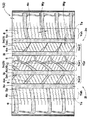
又図2には、本発明の空気入りタイヤ1が、乗用車用のスタッドレスタイヤである場合のトレッドパターンが例示される。同図に示すように、空気入りタイヤ1は、トレッド部2に、タイヤ周方向に連続してのびる縦主溝3と、この縦主溝3に交わる向きの横溝4とを具え、これにより前記トレッド部2に、該トレッド部2が複数のブロック5に区分されたブロックパターンを形成している。
FIG. 2 illustrates a tread pattern when the
前記縦主溝3は、タイヤ軸方向最外側に配される一対の外の縦主溝3oを含み、この外の縦主溝3oによって、前記トレッド部2を、外の縦主溝3oよりもタイヤ軸方向外側のショルダー側領域Yshと、外の縦主溝3o、3o間のクラウン側領域Ycrとに区分している。
The longitudinal
具体的には、縦主溝3は、タイヤ赤道Cの両側をのびる一対の内の縦主溝3iと、その外側に配される前記一対の外の縦主溝3oとの4本の縦主溝3からなり、前記クラウン側領域Ycrをさらに、内の縦主溝3i、3i間の内のクラウン側領域部分Ycr1と、内の縦主溝3iと外の縦主溝3oと間の外のクラウン側領域部分Ycr2とに区分している。
Specifically, the vertical
又前記横溝4は、前記内のクラウン側領域部分Ycr1に配され、この内のクラウン側領域部分Ycr1を中央のブロック5cが周方向に並ぶブロック列に形成する中央の横溝4cと、前記外のクラウン側領域部分Ycr2に配され、この外のクラウン側領域部分Ycr2を中間のブロック5mが周方向に並ぶブロック列に形成する中間の横溝4mと、前記ショルダー側領域Yshに配され、このショルダー側領域Yshを外のブロック5oが周方向に並ぶブロック列に形成する外の横溝4oとから構成される。
The
前記縦主溝3は、その溝巾Wgを3mm以上とした幅広溝である。この縦主溝3では、耐偏摩耗性の観点から、溝壁面とトレッド面とが交わるエッジ部が周方向に直線状にのびることが好ましく、さらには排水性や雪柱せん断力の観点から、溝断面形状を一定として周方向に直線状にのびる直線溝であるのが好ましい。又縦主溝3の溝深さDg(図示しない)は、特に規制されないが、乗用車用のスタッドレスタイヤの場合、8.0〜10.0mmの範囲が一般に採用される。又前記横溝4の溝巾Wy、及び溝深さDy(図示しない)も、従来的なスタッドレスタイヤと同様の範囲が採用でき、例えば前記溝巾Wy、溝深さDyは、前記縦主溝3の溝巾Wg、溝深さDg以下が一般的である。
The vertical
又各前記ブロック5の表面には、サイピング6が形成される。このサイピング6は、そのサイプ長さ方向にジグザグ状にのびるジグザグ部8を有し、サイピング6として、前記ジグザグ部8のみで形成することも、又ジグザグ部8の一端側、及び/又は他端にサイプ長さ方向に沿って直線状にのびる直線状部を形成することもできる。なおサイピング6の巾及び深さも従来的なスタッドレスタイヤと同様の範囲が採用でき、本例ではサイピング6の巾は0.5mm程度、又最大深さは4.0mm程度のものが採用されている。
A
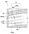
そして本実施形態のタイヤ1では、図3〜5に外、中間、中央のブロック5o、5m、5cをサイピング6とともに示すように、前記サイピング6のうちで、前記ショルダー側領域Yshに配されるサイピング6sh(即ち外のブロック5oに配されるサイピング6sh)のジグザグ部8におけるジグザグの振幅WshおよびジグザグのピッチPshを、前記クラウン側領域Ycrに配されるサイピング6cr(即ち中間及び中央のブロック5m、5cに配されるサイピング6cr)のジグザグ部8におけるジグザグの振幅WcrおよびジグザグのピッチPcrよりもそれぞれ大としている。即ち、Wsh>Wcr かつ Psh>Pcr に設定している。
In the
ここで、ジグザグの振幅およびジグザグのピッチが小なサイピング(小ジグザグのサイピングという場合がある)は、ジグザグの噛み合わせが小でありサイピング壁面間同士の拘束力が弱いため、ブロック剛性を緩和させることができる。その結果、接地する際に、ブロックが柔軟となって動きを持たせることが可能となり、雪上での雪噛み性や排雪性を向上させることができる。従って、本発明の如く、小ジグザグのサイピング6crを、雪上走行への影響が大なクラウン側領域Ycrに配することで、前記雪噛み性や排雪性をより有効に機能させることが可能となり、雪上性能を効果的に高めることができる。 Here, siping with small zigzag amplitude and zigzag pitch (sometimes referred to as small zigzag siping) reduces zigzag engagement and weakens the binding force between siping walls, thus reducing block rigidity. be able to. As a result, when contacting the ground, the block becomes flexible and can move, and the snow biting property and the snow discharging property on the snow can be improved. Therefore, by arranging the small zigzag siping 6cr in the crown side region Ycr that has a great influence on running on snow as in the present invention, it becomes possible to make the snow biting property and snow drainage function more effectively. The performance on snow can be effectively increased.
これに対して、ジグザグの振幅およびジグザグのピッチが大なサイピング(大ジグザグのサイピングという場合がある)は、ジグザグの噛み合わせが大でありサイピング壁面間同士の拘束力が強いため、ブロック剛性を高めることができる。その結果、この大ジグザグのサイピング6shを、ドライ操縦安定性への影響が大きいショルダー側領域Yshに配することにより、旋回時やレーンチェンジ時の横力に対して高い抗力を発揮させることが可能となる。従って、前述のクラウン側領域Ycrにおける小ジグザグのサイピング6crの採用と相俟って、雪上性能を高めつつドライ操縦安定性を向上させることができる。 On the other hand, siping with a large zigzag amplitude and zigzag pitch (sometimes called large zigzag siping) has a large zigzag engagement and a strong restraint force between the siping walls. Can be increased. As a result, this large zigzag siping 6sh can be placed in the shoulder side area Ysh, which has a large impact on dry handling stability, and it is possible to exert a high resistance against lateral forces during turning and lane changes. It becomes. Therefore, combined with the adoption of the small zigzag siping 6cr in the crown side region Ycr described above, it is possible to improve the dry maneuvering stability while improving the performance on snow.
なお前記ジグザグの振幅の比Wsh/Wcrが1.20より小、及びジグザグのピッチの比Psh/Pcrが1.20より小の場合には、ジグザグの大きさの差が過小となり、前述の効果を不充分に発揮することができなくなる。逆に比Wsh/Wcrが2.0より大、及び比Psh/Pcrが3.0より大の場合には、クラウン側領域Ycrに小ジグザグのサイピング6crを採用したことによるドライ操縦安定性へのディメリット、及びショルダー側領域Yshに大ジグザグのサイピング6shを採用したことによる雪上性能へのディメリットが大きくなり、同様に前述の効果を不充分に発揮することができなくなる。従って、比Wsh/Wcrの下限は1.20以上、さらには1.4以上が好ましく、又上限は2.0以下、さらには1.8以下が好ましい。又比Psh/Pcrの下限は1.20以上、さらには1.4以上が好ましく、又上限は3.0以下、さらには2.5以下が好ましい。 When the zigzag amplitude ratio Wsh / Wcr is smaller than 1.20 and the zigzag pitch ratio Psh / Pcr is smaller than 1.20, the difference in zigzag size is too small, and the above-described effect is achieved. Cannot be sufficiently exerted. On the contrary, when the ratio Wsh / Wcr is larger than 2.0 and the ratio Psh / Pcr is larger than 3.0, the dry steering stability is improved by adopting the small zigzag siping 6cr in the crown side region Ycr. The disadvantage and the disadvantage to the performance on the snow due to the adoption of the large zigzag siping 6sh in the shoulder side region Ysh become large, and similarly, the above-mentioned effects cannot be sufficiently exhibited. Therefore, the lower limit of the ratio Wsh / Wcr is preferably 1.20 or more, more preferably 1.4 or more, and the upper limit is preferably 2.0 or less, more preferably 1.8 or less. The lower limit of the ratio Psh / Pcr is preferably 1.20 or more, more preferably 1.4 or more, and the upper limit is preferably 3.0 or less, more preferably 2.5 or less.
又前記サイピング6においては、前記図3〜5に示すように、前記ショルダー側領域Yshに配されるサイピング6shのタイヤ軸方向に対する角度θshを、前記クラウン側領域Ycrに配されるサイピング6crのタイヤ軸方向に対する角度θcrよりも小とすることも重要である。これは、旋回時やレーンチェンジ時の横力に対して高い抗力を発揮させてドライ操縦安定性を向上させるためには、前記ショルダー側領域Yshにおけるタイヤ軸方向のブロック剛性をより高めることが重要であるからであり、そのために前記角度θshを相対的に小としている。又前記クラウン側領域Ycrに配されるサイピング6crの角度θcrを相対的に大とすることで、タイヤ軸方向及び周方向のエッジ成分をそれぞれ増やすことができ、雪路面だけでなく、特に摩擦抵抗μが低い氷路面などの低μ路面におけるグリップ性を高めることができる。
In the
そのためには、サイピング6shの前記角度θshは30°以下が好ましく、これを上回ると、ドライ操縦安定性の低下傾向となる。又前記サイピング6crの前記角度θcrは15〜60°の範囲が好ましく、これを外れると、低μ路面におけるグリップ性を充分に確保するのが難しくなる。このような観点から前記角度θshの上限は20°以下がさらに好ましく、又前記角度θcrでは、その下限を20°以上、上限を40°以下とするのがさらに好ましい。なおサイピング6のタイヤ軸方向に対する角度θsh、θchは、ジグザグ部8におけるジグザグ中心線iのタイヤ軸方向に対する角度を意味し、このジグザグ中心線iが曲線の場合には、その接線のタイヤ軸方向に対する角度で定義する。
For this purpose, the angle θsh of the siping 6sh is preferably 30 ° or less, and if it exceeds this, the dry steering stability tends to decrease. Further, the angle θcr of the siping 6cr is preferably in the range of 15 to 60 °. If the angle θcr is out of this range, it becomes difficult to ensure sufficient grip on the low μ road surface. From such a viewpoint, the upper limit of the angle θsh is more preferably 20 ° or less, and the lower limit of the angle θcr is more preferably 20 ° or more and the upper limit is more preferably 40 ° or less. The angles θsh and θch with respect to the tire axial direction of the
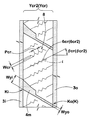
又本例では、前記サイピング6crのうち、内のクラウン側領域部分Ycr1(図5に示す)に配されるサイピング6cr1のタイヤ軸方向に対する傾斜の向きを、前記外のクラウン側領域部分Ycr2(図4に示す)に配されるサイピング6cr2のタイヤ軸方向に対する傾斜の向きと相違させている。具体的には、本例では、サイピング6cr1が「左上り」で傾斜し、サイピング6cr2が「右上り」で傾斜する場合が例示されている。なおサイピング6cr1の傾斜の角度θcr1は、サイピング6cr2の傾斜の角度θcr2とほぼ同角度であって、片流れ防止の観点から、その差|θcr1−θcr2|を15°以下とするのが好ましい。 Further, in this example, the direction of the inclination of the siping 6cr1 disposed in the inner crown side region portion Ycr1 (shown in FIG. 5) of the siping 6cr with respect to the tire axial direction is set to the outer crown side region portion Ycr2 (see FIG. The direction of the inclination with respect to the tire axial direction of the siping 6cr2 arranged in (4) is different. Specifically, in this example, the case where the siping 6cr1 is inclined “upward to the left” and the siping 6cr2 is inclined “upper right” is illustrated. The inclination angle θcr1 of the siping 6cr1 is substantially the same as the inclination angle θcr2 of the siping 6cr2, and the difference | θcr1−θcr2 | is preferably 15 ° or less from the viewpoint of preventing a single flow.
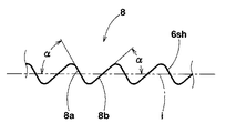
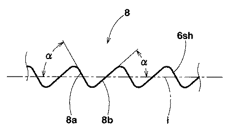
次に、図3に示すように、前記ショルダー側領域Yshに配されるサイピング6shの前記ジグザグ部8は、そのジグザグ中心線iのタイヤ軸方向に対する傾斜の向きが、前記ショルダー側領域Yshに配される外の横溝4oのタイヤ軸方向に対する傾斜の向きと同方向である。本例では、ジグザグ中心線iと外の横溝4oとが、それぞれ右上りに傾斜した場合が示されており、特に本例ではジグザグ中心線iと外の横溝4oとがほぼ並行に配される場合が示される。これにより、ブロック剛性の低下を最小限に抑えることができる。又前記ジグザグ部8は、図6に拡大して示すように、前記ジグザグ中心線iとの交差角度αが大な第1のジグザグ辺8aと、ジグザグ中心線iとの交差角度αが小な第2のジグザグ辺8bとが交互に連なる鋸歯状に形成されている。このとき、前記第1のジグザグ辺8aのタイヤ軸方向に対する傾斜の向きは、ジグザグ中心線iのタイヤ軸方向に対する傾斜の向きと相違し、かつ第2のジグザグ辺8bのタイヤ軸方向に対する傾斜の向きは、ジグザグ中心線iのタイヤ軸方向に対する傾斜の向きと同方向としている。本例では、ジグザグ中心線iと第2のジグザグ辺8bとが右上りに傾斜し、第1のジグザグ辺8aが左上りに傾斜している。このようにジグザグ部8を構成することで、ジグザグ中心線iをタイヤ軸方向に対して傾斜させつつ、特にジグザグ中心線iと外の横溝4oとを平行配列しつつ、第1のジグザグ辺8aのタイヤ軸方向エッジ成分と、第2のジグザグ辺8bのタイヤ軸方向エッジ成分との均衡化、及び第1のジグザグ辺8aの周方向エッジ成分と、第2のジグザグ辺8bの周方向エッジ成分との均衡化を図ることができる。これにより、ショルダー側領域Yshにおけるブロック剛性を高く確保しながら、エッジ効果をバランス化して直進性を高めることができる。
Next, as shown in FIG. 3, the
これに対して、内外のクラウン側領域部分Ycr1、Ycr2においては、そこに配されるサイピング6cr1、6cr2のジグザグ中心線iのタイヤ軸方向に対する傾斜の向きは、内外のクラウン側領域部分Ycr1、Ycr2に配される横溝4c、4mの傾斜の向きと相違している。本例では、内のクラウン側領域部分Ycr1においては、サイピング6cr1のジグザグ中心線iは左上りに傾斜し、又横溝4cは右上りに傾斜している。又
外のクラウン側領域部分Ycr2においては、サイピング6cr2のジグザグ中心線iは右上りに傾斜し、又横溝4mは左上りに傾斜している。特に本例では、サイピング6cr1のジグザグ中心線iと横溝4cとが30°以上の角度で交差し、又サイピング6cr2のジグザグ中心線iと横溝4mとが30°以上の角度で交差している。このような構成とすることで、クラウン側領域Ycrのブロック剛性を、バランス良く緩和でき、雪上性能にとって有利となる。
On the other hand, in the inner and outer crown side region portions Ycr1 and Ycr2, the direction of the inclination of the zigzag center line i of the sipings 6cr1 and 6cr2 disposed therein with respect to the tire axial direction is determined by the inner and outer crown side region portions Ycr1 and Ycr2 This is different from the direction of the inclination of the
なお本例では、前記内の横溝4cは、図5に示すように、緩傾斜の第1の溝部4c1と、急傾斜の第2の溝部4c2とを屈曲点Qで連結した略V字の屈曲溝であり、この内の横溝4c、4c間は、前記屈曲点Qからのびて前記急傾斜の第2の溝部4c2に交わる連結溝10により連結される。これにより排水性や雪上性能のさらなる向上が図られる。なお本例では、前記第2の溝部4c2と連結溝10とは、一つの円弧状曲線として滑らかに連なり、最も排水性が要求されるタイヤ赤道C上での排水性を高めている。
In the present example, the inner
次に、本例のトレッドパターンは、前記図2に示す如く、タイヤ赤道C両側が非対称をなす非対称パーンであって、トレッド部2は、車両装着時にタイヤ赤道Cよりも車両外側となる外のトレッド半部分2oにおけるランド比Loが、車両内側となる内のトレッド半部分2iにおけるランド比Liよりも大に設定される。このように旋回時に大きな荷重が作用する外のトレッド半部分2oに対して、ランド比Loを高めてパターン剛性を増大しているため、前述の優れた雪上性能を確保しながらドライ操縦安定性をさらに向上させることができる。このとき、前記ランド比Loは63.5〜69.5%、ランド比Liは59.5〜65.5%の範囲が好ましく、又その差(Lo−Li)は、雪上性能、ドライ操縦安定性、耐偏摩耗性の観点から2.0〜5.0%の範囲が好ましい。なお前記ランド比は、周知の如く、トレッド接地端Te、Te間におけるトレッド部2の全表面積(溝を全て埋めた状態での表面積)に占める、陸部(ブロック)の表面積の割合を意味する。
Next, as shown in FIG. 2, the tread pattern of the present example is an asymmetrical piane in which both sides of the tire equator C are asymmetric, and the
又本例では、図4、5に示すように、前記クラウン側領域Ycrに配される横溝4m、4cは、そのタイヤ軸方向両端に、前記縦主溝3と交差する交差部Kを有する。そして、車両装着時に車両外側となる外の交差部Koにおける前記横溝の溝巾Wyoは、車両内側となる内の交差部Kiにおける前記横溝の溝巾Wyiよりも小に設定されている。このように、横溝4m、4cにおいて、それぞれ、溝巾Wyo<溝巾Wyiとしているため、車両外側に向かって、パターン剛性を順次増大することができ、前記ランド比Li<ランド比Loと相俟って、ドライ操縦安定性をいっそう向上させることができる。なお横溝4m、4cの溝巾Wyは
外の交差部Koから内の交差部Kiに向かって、滑らかに、及び/又は段階的に増加している。
In this example, as shown in FIGS. 4 and 5, the
以上、本発明の特に好ましい実施形態について詳述したが、本発明は図示の実施形態に限定されることなく、種々の態様に変形して実施しうる。 As mentioned above, although especially preferable embodiment of this invention was explained in full detail, this invention is not limited to embodiment of illustration, It can deform | transform and implement in a various aspect.
図1の基本パターンを有し、かつ表1の仕様に基づきタイヤサイズが205/55R16の乗用車用のスタッドレスタイヤを試作し、ドライ操縦安定性、及び雪上性能についてテストするとともに、その結果を表1に記載した。各タイヤとも、サイピングにおけるジグザグの振幅、及びジグザグのピッチ以外は全て実質的に同仕様である。
(1)ドライ操縦安定性:
下記の条件にて全輪に供試タイヤを装着した車両を使用し、ドライアスファルト路面のタイヤテストコースを走行した時の操縦安定性(レーンチェンジ時の安定性、及び旋回性)を、ドライバーによる官能により、比較例1を100とする指数にて評価した。指数の大なほど良好である。
A prototype studless tire for a passenger car having the basic pattern shown in FIG. 1 and a tire size of 205 / 55R16 based on the specifications shown in Table 1 was tested and tested for dry handling stability and performance on snow. It was described in. Each tire has substantially the same specifications except for the zigzag amplitude and zigzag pitch in siping.
(1) Dry handling stability:
The driving stability (stability at the time of lane change and turning performance) when driving on a tire test course on a dry asphalt road using a vehicle equipped with test tires on all wheels under the following conditions depends on the driver The sensory evaluation was performed using an index with Comparative Example 1 as 100. The higher the index, the better.
リムサイズ:16×6.5J
内圧:200kPa
車両:乗用車(2000ccのFR車)
(2)雪上性能:
上記のテスト車両を用い、雪路タイヤテストコースを走行した時の操縦安定性(トラクション性、レーンチェンジ時の安定性、旋回性)を、ドライバーによる官能により、比較例1を100とする指数にて評価した。指数の大なほど良好である。
Rim size: 16 × 6.5J
Internal pressure: 200 kPa
Vehicle: Passenger car (2000cc FR car)
(2) Performance on snow:
Using the above test vehicle, the steering stability (traction, lane change stability, turning performance) when running on a snowy road tire test course is indexed with Comparative Example 1 as 100 based on the driver's sensuality. And evaluated. The higher the index, the better.
2 トレッド部
3 縦主溝
3i 内の縦主溝
3o 外の縦主溝
4 横溝
5 ブロック
6 サイピング
6sh サイピング
6cr サイピング
6cr1 サイピング
6cr2 サイピング
8 ジグザグ部
8a 第1のジグザグ辺
8b 第2のジグザグ辺
i ジグザグ中心線
K 交差部
SH タイヤショルダ
Te トレッド接地端
Ysh ショルダー側領域
Ycr クラウン側領域
Ycr1 外のクラウン側領域部分
Ycr2 内のクラウン側領域部分
2 Tread
Claims (7)
トレッド接地端を含むタイヤショルダは、タイヤ子午断面における輪郭線が曲率半径25mm以上の円弧曲線からなるラウンドショルダ形状をなし、
かつ前記サイピングは、そのサイプ長さ方向にジグザグ状にのびるジグザグ部を有し、
しかも前記外の縦主溝は、トレッド部を、該外の縦主溝よりもタイヤ軸方向外側のショルダー側領域と、外の縦主溝間のクラウン側領域とに区分するとともに、
前記サイピングのうちで、前記ショルダー側領域に配されるサイピングのジグザグ部におけるジグザグの振幅WshおよびジグザグのピッチPshは、前記クラウン側領域に配されるサイピングのジグザグ部におけるジグザグの振幅WcrおよびジグザグのピッチPcrよりも大であり、
しかも前記ショルダー側領域に配されるサイピングのタイヤ軸方向に対する角度θshは、前記クラウン側領域に配されるサイピングのタイヤ軸方向に対する角度θcrより小であることを特徴とする空気入りタイヤ。 By providing a longitudinal main groove including a pair of outer longitudinal main grooves continuously extending in the tire circumferential direction and arranged on the outermost side in the tire axial direction, and a lateral groove in a direction intersecting with the longitudinal main grooves in the tread portion , A pneumatic tire in which the tread portion is divided into blocks and siping is formed on the blocks,
The tire shoulder including the tread contact edge has a round shoulder shape in which the contour line in the tire meridional section is an arc curve having a curvature radius of 25 mm or more,
And the siping has a zigzag portion extending zigzag in the sipe length direction,
Moreover, the outer vertical main groove divides the tread portion into a shoulder side region on the tire axial direction outer side than the outer vertical main groove and a crown side region between the outer vertical main grooves,
Among the sipings, the zigzag amplitude Wsh and zigzag pitch Psh in the zigzag portion of the siping disposed in the shoulder side region are the zigzag amplitude Wcr and zigzag pitch in the zigzag portion of the siping disposed in the crown side region. Greater than the pitch Pcr,
Moreover, a pneumatic tire characterized in that an angle θsh with respect to the tire axial direction of siping disposed in the shoulder side region is smaller than an angle θcr with respect to the tire axial direction of siping disposed in the crown side region.
前記内のクラウン側領域部分に配されるサイピングのタイヤ軸方向に対する傾斜の向きは、前記外のクラウン側領域部分に配されるサイピングのタイヤ軸方向に対する傾斜の向きと相違することを特徴とする請求項1〜3記載の空気入りタイヤ。 The longitudinal main groove includes two or more of the longitudinal main grooves arranged in the crown side region, and the crown side region includes a crown side region portion between the longitudinal main grooves, It is divided into an outer crown side region portion between the longitudinal main groove and the outer longitudinal main groove,
The direction of inclination of the siping disposed in the inner crown side region portion with respect to the tire axial direction is different from the direction of inclination of the siping disposed in the outer crown side region portion with respect to the tire axial direction. The pneumatic tire according to claim 1.
かつ前記ジグザグ部は、前記ジグザグ中心線との交差角度が大な第1のジグザグ辺と、ジグザグ中心線との交差角度が小な第2のジグザグ辺とが交互に連なる鋸歯状をなすとともに、
前記第1のジグザグ辺のタイヤ軸方向に対する傾斜の向きは、ジグザグ中心線のタイヤ軸方向に対する傾斜の向きと相違し、第2のジグザグ辺のタイヤ軸方向に対する傾斜の向きは、ジグザグ中心線のタイヤ軸方向に対する傾斜の向きと同方向であることを特徴とする請求項1〜4記載の空気入りタイヤ。 In the zigzag portion of the siping disposed in the shoulder side region, the inclination direction of the zigzag center line with respect to the tire axial direction is the same as the inclination direction of the lateral groove disposed in the shoulder side region with respect to the tire axial direction. Yes,
And the zigzag portion has a sawtooth shape in which a first zigzag side having a large intersection angle with the zigzag centerline and a second zigzag side having a small intersection angle with the zigzag centerline are alternately connected,
The direction of inclination of the first zigzag side with respect to the tire axial direction is different from the direction of inclination of the zigzag center line with respect to the tire axial direction, and the direction of inclination of the second zigzag side with respect to the tire axial direction is different from that of the zigzag center line. The pneumatic tire according to claim 1, wherein the direction is the same as the direction of inclination with respect to the tire axial direction.
Priority Applications (6)
| Application Number | Priority Date | Filing Date | Title |
|---|---|---|---|
| JP2008325970A JP4759044B2 (en) | 2008-12-22 | 2008-12-22 | Pneumatic tire |
| US12/612,721 US8578985B2 (en) | 2008-12-22 | 2009-11-05 | Pneumatic tire with sipes |
| EP09014498.1A EP2199111B1 (en) | 2008-12-22 | 2009-11-20 | Pneumatic tire with sipes |
| KR1020090114608A KR101581960B1 (en) | 2008-12-22 | 2009-11-25 | Pneumatic tire |
| CN200910225699.0A CN101758745B (en) | 2008-12-22 | 2009-11-27 | Pneumatic tire |
| RU2009147155/11A RU2508204C2 (en) | 2008-12-22 | 2009-12-21 | Pneumatic tire with slitted drain grooves |
Applications Claiming Priority (1)
| Application Number | Priority Date | Filing Date | Title |
|---|---|---|---|
| JP2008325970A JP4759044B2 (en) | 2008-12-22 | 2008-12-22 | Pneumatic tire |
Publications (2)
| Publication Number | Publication Date |
|---|---|
| JP2010143532A true JP2010143532A (en) | 2010-07-01 |
| JP4759044B2 JP4759044B2 (en) | 2011-08-31 |
Family
ID=42083926
Family Applications (1)
| Application Number | Title | Priority Date | Filing Date |
|---|---|---|---|
| JP2008325970A Expired - Fee Related JP4759044B2 (en) | 2008-12-22 | 2008-12-22 | Pneumatic tire |
Country Status (6)
| Country | Link |
|---|---|
| US (1) | US8578985B2 (en) |
| EP (1) | EP2199111B1 (en) |
| JP (1) | JP4759044B2 (en) |
| KR (1) | KR101581960B1 (en) |
| CN (1) | CN101758745B (en) |
| RU (1) | RU2508204C2 (en) |
Cited By (8)
| Publication number | Priority date | Publication date | Assignee | Title |
|---|---|---|---|---|
| JP4905599B1 (en) * | 2011-04-27 | 2012-03-28 | 横浜ゴム株式会社 | Pneumatic tire |
| JP2012218596A (en) * | 2011-04-08 | 2012-11-12 | Toyo Tire & Rubber Co Ltd | Pneumatic tire |
| JP2012250610A (en) * | 2011-06-02 | 2012-12-20 | Yokohama Rubber Co Ltd:The | Pneumatic tire |
| JP2013028314A (en) * | 2011-07-29 | 2013-02-07 | Sumitomo Rubber Ind Ltd | Pneumatic tire |
| WO2013099675A1 (en) * | 2011-12-28 | 2013-07-04 | 住友ゴム工業株式会社 | Pneumatic tire |
| KR20130127922A (en) * | 2012-05-15 | 2013-11-25 | 스미토모 고무 고교 가부시키가이샤 | Pneumatic tire |
| JP2015131642A (en) * | 2015-04-20 | 2015-07-23 | 株式会社ブリヂストン | pneumatic tire |
| JP2021094922A (en) * | 2019-12-13 | 2021-06-24 | Toyo Tire株式会社 | Pneumatic tire |
Families Citing this family (19)
| Publication number | Priority date | Publication date | Assignee | Title |
|---|---|---|---|---|
| JP5012357B2 (en) * | 2007-09-20 | 2012-08-29 | 横浜ゴム株式会社 | Pneumatic tire |
| DE102011000813A1 (en) * | 2011-02-18 | 2012-08-23 | Continental Reifen Deutschland Gmbh | Tread pattern of a pneumatic vehicle tire |
| DE102011055915A1 (en) * | 2011-12-01 | 2013-06-06 | Continental Reifen Deutschland Gmbh | Vehicle tires |
| JP6329010B2 (en) * | 2014-06-13 | 2018-05-23 | 株式会社ブリヂストン | Pneumatic tire |
| DE102014226449A1 (en) * | 2014-12-18 | 2016-06-23 | Continental Reifen Deutschland Gmbh | Vehicle tires |
| FR3042738B1 (en) * | 2015-10-27 | 2017-11-24 | Michelin & Cie | PNEUMATIC WORKING LAYER COMPRISING MONOFILAMENTS AND GROOVED ROLLING BELT |
| JP6701919B2 (en) * | 2016-04-26 | 2020-05-27 | 横浜ゴム株式会社 | Pneumatic tire |
| JP6885170B2 (en) * | 2017-04-10 | 2021-06-09 | 住友ゴム工業株式会社 | Pneumatic tires |
| JP6859175B2 (en) * | 2017-04-27 | 2021-04-14 | Toyo Tire株式会社 | Pneumatic tires |
| EP3638517B1 (en) * | 2017-06-12 | 2021-05-12 | Pirelli Tyre S.p.A. | Tyre for vehicle wheels |
| JP2019104415A (en) * | 2017-12-13 | 2019-06-27 | Toyo Tire株式会社 | Pneumatic tire |
| JP7035740B2 (en) * | 2018-04-06 | 2022-03-15 | 住友ゴム工業株式会社 | tire |
| CN108482019B (en) * | 2018-05-30 | 2023-10-17 | 万达集团股份有限公司 | High-drainage pattern tire |
| EP3744537B1 (en) * | 2019-05-31 | 2021-12-08 | Sumitomo Rubber Industries, Ltd. | Tire |
| DE102019220135A1 (en) * | 2019-12-19 | 2021-06-24 | Continental Reifen Deutschland Gmbh | Pneumatic vehicle tires |
| CN111216497B (en) * | 2020-02-28 | 2022-05-31 | 安徽佳通乘用子午线轮胎有限公司 | Winter tyre with zigzag tread pattern |
| DE102020208125A1 (en) * | 2020-06-30 | 2021-12-30 | Continental Reifen Deutschland Gmbh | Pneumatic vehicle tires |
| JP7610971B2 (en) * | 2020-12-21 | 2025-01-09 | Toyo Tire株式会社 | Pneumatic tires |
| JP2023066314A (en) * | 2021-10-28 | 2023-05-15 | 株式会社ブリヂストン | tire |
Citations (4)
| Publication number | Priority date | Publication date | Assignee | Title |
|---|---|---|---|---|
| JPH11310013A (en) * | 1998-04-28 | 1999-11-09 | Toyo Tire & Rubber Co Ltd | Pneumatic radial tire |
| JP2005297880A (en) * | 2004-04-15 | 2005-10-27 | Bridgestone Corp | Pneumatic tire |
| JP2008155685A (en) * | 2006-12-21 | 2008-07-10 | Toyo Tire & Rubber Co Ltd | Pneumatic tire |
| JP2008201319A (en) * | 2007-02-21 | 2008-09-04 | Sumitomo Rubber Ind Ltd | studless tire |
Family Cites Families (11)
| Publication number | Priority date | Publication date | Assignee | Title |
|---|---|---|---|---|
| DE3540668C2 (en) * | 1985-11-16 | 1994-09-22 | Continental Ag | Pneumatic vehicle tires |
| JPS62265006A (en) * | 1986-05-14 | 1987-11-17 | Bridgestone Corp | Pneumatic tire |
| JPS63305009A (en) * | 1987-06-03 | 1988-12-13 | Yokohama Rubber Co Ltd:The | Tread pattern |
| JP2973024B2 (en) | 1990-10-22 | 1999-11-08 | 横浜ゴム株式会社 | Pneumatic tire |
| JPH06239110A (en) * | 1993-02-19 | 1994-08-30 | Ohtsu Tire & Rubber Co Ltd :The | Pneumatic tire for automobile |
| JP3878751B2 (en) * | 1998-09-22 | 2007-02-07 | 横浜ゴム株式会社 | Pneumatic tires for snow and snow |
| JP2005041393A (en) | 2003-07-24 | 2005-02-17 | Bridgestone Corp | Pneumatic tire |
| DE10352149A1 (en) | 2003-11-04 | 2005-06-02 | Continental Aktiengesellschaft | Vehicle tires |
| JP4294532B2 (en) * | 2004-04-09 | 2009-07-15 | 株式会社ブリヂストン | Pneumatic tire |
| EP1787826B1 (en) | 2004-08-25 | 2010-06-16 | Bridgestone Corporation | Pneumatic tire |
| DE102005058363A1 (en) | 2005-12-06 | 2007-06-14 | Continental Aktiengesellschaft | Tread pattern |
-
2008
- 2008-12-22 JP JP2008325970A patent/JP4759044B2/en not_active Expired - Fee Related
-
2009
- 2009-11-05 US US12/612,721 patent/US8578985B2/en not_active Expired - Fee Related
- 2009-11-20 EP EP09014498.1A patent/EP2199111B1/en not_active Not-in-force
- 2009-11-25 KR KR1020090114608A patent/KR101581960B1/en not_active Expired - Fee Related
- 2009-11-27 CN CN200910225699.0A patent/CN101758745B/en not_active Expired - Fee Related
- 2009-12-21 RU RU2009147155/11A patent/RU2508204C2/en active
Patent Citations (4)
| Publication number | Priority date | Publication date | Assignee | Title |
|---|---|---|---|---|
| JPH11310013A (en) * | 1998-04-28 | 1999-11-09 | Toyo Tire & Rubber Co Ltd | Pneumatic radial tire |
| JP2005297880A (en) * | 2004-04-15 | 2005-10-27 | Bridgestone Corp | Pneumatic tire |
| JP2008155685A (en) * | 2006-12-21 | 2008-07-10 | Toyo Tire & Rubber Co Ltd | Pneumatic tire |
| JP2008201319A (en) * | 2007-02-21 | 2008-09-04 | Sumitomo Rubber Ind Ltd | studless tire |
Cited By (14)
| Publication number | Priority date | Publication date | Assignee | Title |
|---|---|---|---|---|
| JP2012218596A (en) * | 2011-04-08 | 2012-11-12 | Toyo Tire & Rubber Co Ltd | Pneumatic tire |
| US9016338B2 (en) | 2011-04-27 | 2015-04-28 | The Yokohama Rubber Co., Ltd. | Pneumatic tire |
| JP4905599B1 (en) * | 2011-04-27 | 2012-03-28 | 横浜ゴム株式会社 | Pneumatic tire |
| JP2012250610A (en) * | 2011-06-02 | 2012-12-20 | Yokohama Rubber Co Ltd:The | Pneumatic tire |
| JP2013028314A (en) * | 2011-07-29 | 2013-02-07 | Sumitomo Rubber Ind Ltd | Pneumatic tire |
| WO2013099675A1 (en) * | 2011-12-28 | 2013-07-04 | 住友ゴム工業株式会社 | Pneumatic tire |
| JP2013139168A (en) * | 2011-12-28 | 2013-07-18 | Sumitomo Rubber Ind Ltd | Pneumatic tire |
| US9809060B2 (en) | 2011-12-28 | 2017-11-07 | Sumitomo Rubber Industries, Ltd. | Pneumatic tire |
| KR20130127922A (en) * | 2012-05-15 | 2013-11-25 | 스미토모 고무 고교 가부시키가이샤 | Pneumatic tire |
| JP2013237360A (en) * | 2012-05-15 | 2013-11-28 | Sumitomo Rubber Ind Ltd | Pneumatic tire |
| KR101857830B1 (en) * | 2012-05-15 | 2018-06-20 | 스미토모 고무 고교 가부시키가이샤 | Pneumatic tire |
| JP2015131642A (en) * | 2015-04-20 | 2015-07-23 | 株式会社ブリヂストン | pneumatic tire |
| JP2021094922A (en) * | 2019-12-13 | 2021-06-24 | Toyo Tire株式会社 | Pneumatic tire |
| JP7474046B2 (en) | 2019-12-13 | 2024-04-24 | Toyo Tire株式会社 | Pneumatic tires |
Also Published As
| Publication number | Publication date |
|---|---|
| RU2009147155A (en) | 2011-06-27 |
| RU2508204C2 (en) | 2014-02-27 |
| EP2199111B1 (en) | 2014-04-02 |
| KR101581960B1 (en) | 2015-12-31 |
| EP2199111A3 (en) | 2013-03-06 |
| US8578985B2 (en) | 2013-11-12 |
| US20100154952A1 (en) | 2010-06-24 |
| JP4759044B2 (en) | 2011-08-31 |
| CN101758745A (en) | 2010-06-30 |
| EP2199111A2 (en) | 2010-06-23 |
| CN101758745B (en) | 2014-03-05 |
| KR20100073983A (en) | 2010-07-01 |
Similar Documents
| Publication | Publication Date | Title |
|---|---|---|
| JP4759044B2 (en) | Pneumatic tire | |
| JP6346630B2 (en) | Pneumatic tire | |
| JP6852408B2 (en) | tire | |
| KR101793632B1 (en) | Pneumatic tire | |
| CN108621707B (en) | Tyre for vehicle wheels | |
| JP7081229B2 (en) | tire | |
| JP5432967B2 (en) | Pneumatic tire | |
| KR101962976B1 (en) | Pneumatic tire | |
| JP6724379B2 (en) | Pneumatic tire | |
| JP5932761B2 (en) | Pneumatic tire | |
| JP2017190123A (en) | Pneumatic tire | |
| JP2008307918A (en) | Pneumatic tire | |
| JP6790495B2 (en) | tire | |
| JP7081277B2 (en) | tire | |
| JP6907777B2 (en) | tire | |
| JP5798586B2 (en) | Pneumatic tire | |
| JP6558297B2 (en) | Pneumatic tire | |
| CN112238712B (en) | tire | |
| CN107878120B (en) | Pneumatic tires | |
| JP7056333B2 (en) | tire | |
| JP5480866B2 (en) | Pneumatic tire | |
| JP4025120B2 (en) | Pneumatic tire | |
| JP5282479B2 (en) | Pneumatic tire | |
| JP6551028B2 (en) | Pneumatic tire | |
| JP2013103567A (en) | Pneumatic tire |
Legal Events
| Date | Code | Title | Description |
|---|---|---|---|
| A977 | Report on retrieval |
Free format text: JAPANESE INTERMEDIATE CODE: A971007 Effective date: 20101111 |
|
| A131 | Notification of reasons for refusal |
Free format text: JAPANESE INTERMEDIATE CODE: A131 Effective date: 20101130 |
|
| A521 | Request for written amendment filed |
Free format text: JAPANESE INTERMEDIATE CODE: A523 Effective date: 20110126 |
|
| A131 | Notification of reasons for refusal |
Free format text: JAPANESE INTERMEDIATE CODE: A131 Effective date: 20110301 |
|
| A521 | Request for written amendment filed |
Free format text: JAPANESE INTERMEDIATE CODE: A523 Effective date: 20110304 |
|
| TRDD | Decision of grant or rejection written | ||
| A01 | Written decision to grant a patent or to grant a registration (utility model) |
Free format text: JAPANESE INTERMEDIATE CODE: A01 Effective date: 20110524 |
|
| A01 | Written decision to grant a patent or to grant a registration (utility model) |
Free format text: JAPANESE INTERMEDIATE CODE: A01 |
|
| A61 | First payment of annual fees (during grant procedure) |
Free format text: JAPANESE INTERMEDIATE CODE: A61 Effective date: 20110603 |
|
| R150 | Certificate of patent or registration of utility model |
Ref document number: 4759044 Country of ref document: JP Free format text: JAPANESE INTERMEDIATE CODE: R150 Free format text: JAPANESE INTERMEDIATE CODE: R150 |
|
| FPAY | Renewal fee payment (event date is renewal date of database) |
Free format text: PAYMENT UNTIL: 20140610 Year of fee payment: 3 |
|
| R250 | Receipt of annual fees |
Free format text: JAPANESE INTERMEDIATE CODE: R250 |
|
| R250 | Receipt of annual fees |
Free format text: JAPANESE INTERMEDIATE CODE: R250 |
|
| R250 | Receipt of annual fees |
Free format text: JAPANESE INTERMEDIATE CODE: R250 |
|
| R250 | Receipt of annual fees |
Free format text: JAPANESE INTERMEDIATE CODE: R250 |
|
| R250 | Receipt of annual fees |
Free format text: JAPANESE INTERMEDIATE CODE: R250 |
|
| R250 | Receipt of annual fees |
Free format text: JAPANESE INTERMEDIATE CODE: R250 |
|
| R250 | Receipt of annual fees |
Free format text: JAPANESE INTERMEDIATE CODE: R250 |
|
| R250 | Receipt of annual fees |
Free format text: JAPANESE INTERMEDIATE CODE: R250 |
|
| R250 | Receipt of annual fees |
Free format text: JAPANESE INTERMEDIATE CODE: R250 |
|
| LAPS | Cancellation because of no payment of annual fees |