JP2005297880A - Pneumatic tire - Google Patents
Pneumatic tire Download PDFInfo
- Publication number
- JP2005297880A JP2005297880A JP2004119821A JP2004119821A JP2005297880A JP 2005297880 A JP2005297880 A JP 2005297880A JP 2004119821 A JP2004119821 A JP 2004119821A JP 2004119821 A JP2004119821 A JP 2004119821A JP 2005297880 A JP2005297880 A JP 2005297880A
- Authority
- JP
- Japan
- Prior art keywords
- circumferential groove
- tread
- grooves
- center
- groove
- Prior art date
- Legal status (The legal status is an assumption and is not a legal conclusion. Google has not performed a legal analysis and makes no representation as to the accuracy of the status listed.)
- Granted
Links
- 230000001133 acceleration Effects 0.000 abstract description 12
- 239000010426 asphalt Substances 0.000 description 4
- 230000000052 comparative effect Effects 0.000 description 4
- 238000009434 installation Methods 0.000 description 3
- 238000005192 partition Methods 0.000 description 3
- XLYOFNOQVPJJNP-UHFFFAOYSA-N water Substances O XLYOFNOQVPJJNP-UHFFFAOYSA-N 0.000 description 3
- 238000011156 evaluation Methods 0.000 description 2
- 230000008094 contradictory effect Effects 0.000 description 1
- 230000002498 deadly effect Effects 0.000 description 1
- 230000002349 favourable effect Effects 0.000 description 1
- 238000005259 measurement Methods 0.000 description 1
- 230000008520 organization Effects 0.000 description 1
Images
Landscapes
- Tires In General (AREA)
Abstract
Description
本発明は、ネガティブキャンバを付与した状態の下での、操舵性と加減速性能との両立を図った、非対称パターンを有して車両への装着姿勢が指定された空気入りタイヤに関するものである。 The present invention relates to a pneumatic tire having an asymmetric pattern and designated to be mounted on a vehicle, which achieves both steering performance and acceleration / deceleration performance under a state where a negative camber is applied. .
トレッド踏面は、操舵時にはタイヤの横方向の力を路面に伝え、加減速時には前後方向の力を路面に伝える。これらの各々の方向の力を高める手段は、相反するものであり、横方向の力を高めるためには一般に、トレッド踏面のネガティブ率とサイプ密度を下げて、トレッド踏面の陸部剛性を高める必要があり、一方、前後方向の力を高めるためには、トレッド踏面のネガティブ率とサイプ密度をある程度の値に保ち、陸部にしなやかさを付与して路面グリップ力を高める必要がある。また後者においては、ネガティブ率をある程度の値に保つことによる排水性能の確保も必要になる。このため従来の対称パターンでは、要求される横方向の力と前後方向の力を得るための妥協策として、中庸の陸部剛性を選択して、操舵性と加減速性能とを両立させることが行われてきた。 The tread tread transmits the lateral force of the tire to the road during steering, and transmits the longitudinal force to the road during acceleration / deceleration. These means of increasing the force in each direction are contradictory, and in order to increase the lateral force, it is generally necessary to lower the tread tread surface negative rate and sipe density to increase the tread tread surface land rigidity. On the other hand, in order to increase the force in the front-rear direction, it is necessary to maintain the negative rate and the sipe density of the tread surface to a certain level and to give the land portion flexibility to increase the road surface grip force. In the latter case, it is also necessary to ensure drainage performance by keeping the negative rate at a certain value. For this reason, in the conventional symmetrical pattern, as a compromise to obtain the required lateral force and longitudinal force, it is possible to select the middle land rigidity to achieve both steering and acceleration / deceleration performance. Has been done.
ところで、近年の車両におけるホイールアライメントの設定、なかでもキャンバの設定は、ネガティブキャンバが主流となってきており、これによれば、操舵時にはトレッド踏面の装着外側部分の接地面積および接地圧が相対的に高まり、直進加減速時にはトレッド踏面の装着内側部分の接地面積および接地圧が相対的に高まる傾向にあるため、従来の左右対称のトレッドパターンでは、両性能をうまく、両立させることが困難である一方で非対称のトレッドパターンをもって装着外側部分および内側部分のそれぞれを機能分離させた場合には、両性能をうまく両立させることが可能となる。
非対称パターンとしては、特開平5−229310号公報に記載されているようなパターンがあるが、加減速性能および操舵性を、両立させるには依然として十分ではなかった。
As an asymmetric pattern, there is a pattern as described in JP-A-5-229310, but it is still not sufficient to achieve both acceleration / deceleration performance and steering performance.
この発明は、従来技術が抱えるこのような問題点を解決することを課題とするものであり、それの目的とするところは、ネガティブキャンバを付与した条件において、タイヤの操舵性と加減速性能とを高い次元で両立させた空気入りタイヤを提供することにある。 An object of the present invention is to solve such problems of the prior art, and the object of the present invention is to provide tire steerability and acceleration / deceleration performance under conditions where a negative camber is provided. The object is to provide a pneumatic tire that balances the tires at a high level.
本発明に係る空気入りタイヤは、トレッド踏面部に、タイヤ赤道線を隔てて位置してトレッド周方向に連続して延びる一対のセンター周溝を設け、それらのセンター周溝とトレッド踏面端との間にトレッド周方向に連続して延びる一対のサイド周溝を設けて、サイド周溝とトレッド踏面端との間にショルダー陸部を区画し、センター周溝とサイド周溝との間に中間陸部を区画してなる車両への装着姿勢が指定された非対称パターンを有する空気入りタイヤであって、
タイヤ赤道線より、装着内側部分のネガティブ率を、装着外側部分のネガティブ率に比して2〜5%大きくし、
装着内側のショルダー陸部に、トレッド踏面端とサイド周溝とを連通する複数の横溝を設けるとともに、隣り合う横溝のほぼ中央に位置して、トレッド踏面端からサイド周溝に向けて伸びてサイド周溝の手前で終了する複数の行止り横溝と、行止り横溝の終了端とサイド周溝とを連通する複数のサイプとを設け、
装着外側のショルダー陸部に、サイド周溝とトレッド踏面端とを連通する複数の横溝を設けるとともに、隣り合う横溝のほぼ中央に位置して、トレッド踏面端とサイド周溝とを連通するサイプを設け、
装着内側の中間陸部に、サイド周溝からセンター周溝に向かって延びてセンター周溝の手前で終了する複数の行止り傾斜溝を設けるとともに、行止り傾斜溝の終了端からトレッド周方向に向かって延び、隣接する傾斜溝の手前で終了する行止り周方向溝を設け、この行止り周方向溝の終了端と、隣接する行止り傾斜溝の終了端とを連通する周方向サイプを設け、隣り合う行止り傾斜溝のほぼ中央に位置して行止り周方向溝もしくは周方向サイプとサイド周溝とを連通するサイプを設け、
装着外側の中間陸部に、サイド周溝とセンター周溝とを連通する複数の傾斜溝を設け、隣り合う傾斜溝のほぼ中央に位置して、サイド周溝からセンター周溝に向かって延びてセンター周溝の手前で終了する複数のサイプを設けてなる。
The pneumatic tire according to the present invention is provided with a pair of center circumferential grooves that are located on the tread tread surface portion and that extend continuously in the tread circumferential direction with the tire equator line therebetween, and between the center circumferential groove and the tread tread edge. A pair of side circumferential grooves that extend continuously in the tread circumferential direction are provided, a shoulder land is defined between the side circumferential groove and the tread tread edge, and an intermediate land is formed between the center circumferential groove and the side circumferential groove. A pneumatic tire having an asymmetric pattern in which a mounting posture on a vehicle formed by dividing a part is specified,
From the tire equator line, the negative rate of the inner part of the wearing is 2-5% larger than the negative rate of the outer part of the wearing,
A plurality of lateral grooves that connect the tread tread edge and the side circumferential groove are provided on the shoulder land portion on the inner side of the mounting, and are located at the approximate center of the adjacent lateral grooves and extend from the tread tread edge toward the side circumferential groove. A plurality of dead-end lateral grooves that end before the circumferential groove, and a plurality of sipes that communicate the end edge of the dead-end lateral groove and the side circumferential groove,
A plurality of lateral grooves that communicate the side circumferential groove and the tread tread edge are provided on the shoulder land portion on the outer side of the wearing, and a sipe that communicates between the tread tread edge and the side circumferential groove is located substantially at the center of the adjacent lateral groove. Provided,
A plurality of dead-falling grooves extending from the side circumferential groove toward the central circumferential groove and ending before the central circumferential groove are provided in the intermediate land portion on the inner side of the mounting, and in the tread circumferential direction from the end of the dead-falling groove. A dead end circumferential groove extending toward the end of the adjacent inclined groove is provided, and a circumferential sipe is provided to communicate the end end of the dead end circumferential groove with the end end of the adjacent stop inclined groove. A sipe that is located approximately in the middle of the adjacent dead end inclined groove and communicates between the dead end circumferential groove or the circumferential sipe and the side circumferential groove,
A plurality of inclined grooves that connect the side circumferential groove and the center circumferential groove are provided in the intermediate land portion on the outer side of the mounting, and are located at substantially the center of the adjacent inclined grooves and extend from the side circumferential groove toward the center circumferential groove. A plurality of sipes ending before the center circumferential groove are provided.
これによれば、タイヤ赤道線より、装着内側のトレッド踏面部のネガティブ率を、装着外側のトレッド踏面部のネガティブ率に比して2〜5%大きくすることにより、装着外側のトレッド踏面部の剛性をより高めて操舵性の向上に寄与させるとともに、装着内側のトレッド踏面部にしなやかさを付与して路面グリップ力を高めて、加減速性能の向上に寄与させることができる。
また、ネガティブキャンバを付与した条件の下では、直進時に接地面積が大きくなり、接地圧が高くなる装着内側のショルダー陸部に、横溝を形成することに加えて、サイプより広幅の行止り横溝を形成することで区画されるブロックをよりしなやかなものとするとともに、ネガティブ率を増加させて、排水性能を高めることができる。
さらに、装着内側の中間陸部に、行止り傾斜溝と、行止り周方向溝と、周方向サイプとを組み合わせて設けることにより、傾斜溝をセンター周溝に開口させる場合に比べ、行止り傾斜溝と行止り周方向溝のトータル溝体積を大きくしてネガティブ率を大きくでき、かつ、それぞれの溝と周方向サイプとに囲繞されるブロックの表面寸法を小さくしてしなやかなものとするとができるため、トレッド踏面のタイヤ赤道線よりも装着内側の部分をしなやかなものとして加減速性能を高めることができる。
また、センター周溝と行止り傾斜溝および行止り周方向溝およびサイプとにより中間陸部のセンター周溝側にトレッド周方向に連続するリブが形成されるため、微小舵角における操舵性をも向上することができる。
According to this, by making the negative rate of the tread tread part on the inner side of the tire 2-5% larger than the negative rate of the tread tread part on the outer side of the tire equator line, The rigidity can be further increased to contribute to the improvement of steering performance, and the tread surface portion on the inner side of the mounting can be given flexibility to increase the road surface grip force, thereby contributing to the improvement of acceleration / deceleration performance.
In addition, under the condition that a negative camber is applied, in addition to forming a lateral groove in the shoulder land portion on the inner side where the ground contact area increases and the ground pressure increases when going straight, a dead groove lateral groove wider than Sipe is formed. By forming the blocks that are partitioned, the drainage performance can be enhanced by increasing the negative rate.
Furthermore, compared to the case where the inclined groove is opened to the center circumferential groove by providing a combination of the dead slope groove, the dead circumferential groove, and the circumferential sipe in the middle land portion on the inner side of the installation, the dead slope is increased. The total groove volume of the groove and the dead-end circumferential groove can be increased to increase the negative rate, and the surface dimensions of the blocks surrounded by the respective grooves and the circumferential sipe can be reduced to be supple. Therefore, acceleration / deceleration performance can be enhanced by making the inner part of the tread tread surface more flexible than the tire equator line.
In addition, since the center circumferential groove, the dead slope groove, the dead circumferential groove and the sipe form a continuous rib in the tread circumferential direction on the center circumferential groove side of the intermediate land portion, the steering performance at a small steering angle is also achieved. Can be improved.
さらに、操舵時に接地面積が大きくなり接地圧が高くなる、装着外側の中間陸部では、サイプの設け方を最小限度のものとして、実質的には傾斜溝間に区画されるブロックの剛性を高めることに加えて、装着外側のショルダー陸部においても、サイプの設け方を最小限度のものとして、陸部剛性を高めることにより、操舵性を高めることができる。また、装着内側の中間陸部のサイプをセンター周溝に開口させないことにより、装着外側の中間陸部のセンター周溝よりにリブに近い機能を発揮させることができるため、微小舵角における操舵性を向上することができる。また、操舵性を高めることができる。 Furthermore, in the middle land area outside the installation, where the ground contact area increases and the ground pressure increases during steering, the installation of sipes is minimized and the rigidity of the blocks partitioned between the inclined grooves is substantially increased. In addition, also in the shoulder land portion on the outer side of the wearing, the steering performance can be enhanced by increasing the rigidity of the land portion by minimizing the way of providing the sipe. In addition, by not opening the sipe of the middle land portion on the inner side of the mounting to the center circumferential groove, it is possible to exert a function closer to the rib than the center circumferential groove of the middle land portion on the outer side of the mounting. Can be improved. Further, the steering performance can be improved.
ここで好ましくは、請求項2に記載したように、行止り横溝の、幅を2〜6mmとし、深さをセンターおよびサイド周溝の深さの0.6〜0.9倍とするとともに、タイヤ幅方向に延びるサイプの、幅を0.5〜1.1mmとし、深さをセンターおよびサイド周溝の深さの0.6〜0.9倍とする。
ここでタイヤ幅方向に延びるとは、タイヤ幅方向に対して70度傾斜しているものまでを含むものとする。
これによれば、上記に述べたような操舵性の向上と加減速性能の向上および排水性能の向上を、バランスよく両立させることができる。
Preferably, as described in claim 2, the width of the dead groove is 2 to 6 mm, the depth is 0.6 to 0.9 times the depth of the center and side circumferential grooves, The width of the sipe extending in the tire width direction is 0.5 to 1.1 mm, and the depth is 0.6 to 0.9 times the depth of the center and side circumferential grooves.
Here, “extending in the tire width direction” includes up to 70 ° incline with respect to the tire width direction.
According to this, it is possible to balance the improvement in steering performance, the acceleration / deceleration performance, and the drainage performance as described above in a well-balanced manner.
さらに好ましくは、請求項3に記載したように、一対のセンター周溝の間にセンターリブを区画し、リブに、それの幅方向中央部分で終了する複数のサイプを設ける。
これによれば、センターリブにより微小舵角に対する安定した操舵性を得るとともに、センターリブの耐発熱性を向上することができる。
More preferably, as described in claim 3, a center rib is defined between the pair of center circumferential grooves, and a plurality of sipes ending at the center portion in the width direction are provided on the rib.
According to this, it is possible to obtain stable steering performance with respect to a minute rudder angle by the center rib and to improve the heat resistance of the center rib.
以上に述べたところから明らかなように、本発明の空気入りタイヤによれば、ネガティブキャンバを付与した条件において、タイヤの操舵性と加減速性能とを高い次元で両立させることができる。 As is apparent from the above description, according to the pneumatic tire of the present invention, it is possible to achieve both the steering performance and acceleration / deceleration performance of the tire at a high level under the condition where the negative camber is applied.
以下に、本発明の実施の形態を、図面に示すところに基づいて説明する。
図1は、本発明の実施の形態を、車両への装着姿勢の正面視で示すトレッドパターンの展開図である。
ここでは、トレッド踏面部1に、タイヤ赤道線Cを隔てて位置して、トレッド周方向に直線状に連続して延在する一対のセンター周溝2、3を設け、そのセンター周溝2とセンター周溝3によりセンターリブ4を区画し、それらのセンター周溝2、3とトレッド踏面端との間にタイヤ赤道線Cをトレッド幅Wのほぼ1/4隔てて位置してトレッド周方向に連続して延びる一対のサイド周溝5、6を設けて、サイド周溝6とトレッド踏面端との間に装着内側のショルダー陸部7を区画し、センター周溝3とサイド周溝6との間に装着内側の中間陸部8を区画し、センター周溝2とサイド周溝5との間に装着外側の中間陸部9を区画し、サイド周溝5とトレッド踏面端との間に装着外側のショルダー陸部10を区画する。
Hereinafter, embodiments of the present invention will be described with reference to the drawings.
FIG. 1 is a development view of a tread pattern showing an embodiment of the present invention in a front view of a mounting posture on a vehicle.
Here, the tread tread portion 1 is provided with a pair of center circumferential grooves 2, 3 that are located across the tire equator line C and extend linearly in the tread circumferential direction. A center rib 4 is defined by the center circumferential groove 3, and the tire equator line C is located approximately 1/4 of the tread width W between the center circumferential grooves 2, 3 and the tread tread edge in the tread circumferential direction. A pair of side
タイヤ赤道線Cより、装着内側のトレッド踏面部のネガティブ率を、装着外側のトレッド踏面部のネガティブ率に比して2〜5%大きくし、
装着内側のショルダー陸部7に、トレッド踏面端とサイド周溝6とを連通する複数の横溝11を設けてブロック12を区画するとともに、隣り合う横溝11のほぼ中央に位置して、トレッド踏面端からサイド周溝6に向けて伸びサイド周溝6の手前で終了する複数の行止り横溝13と、行止り横溝13の終了端とサイド周溝とを連通する複数のサイプ14とを設け、
装着外側のショルダー陸部10に、サイド周溝5とトレッド踏面端とを連通する複数の横溝15を設けてブロック16を区画するとともに、隣り合う横溝15のほぼ中央に位置して、トレッド踏面端とサイド周溝とを連通するサイプ17を設ける。
装着内側の中間陸部8に、サイド周溝6からセンター周溝3に向かって延びセンター周溝3の手前で終了する複数の行止り傾斜溝18を設けるとともに、行止り傾斜溝18の終了端からトレッド周方向に向かって延び、隣接する行止り傾斜溝18の手前で終了する行止り周方向溝19を設け、行止り周方向溝19の終了端と隣接する行止り傾斜溝18の終了端とを連通する周方向サイプ20を設け、これにより、中間陸部8を、周方向に連続するリブ21と、ブロック22とに区画する。ブロック22には、隣接する行止り傾斜溝18のほぼ中央にサイプ23を設ける。
装着外側の中間陸部9に、サイド周溝5とセンター周溝2とを連通する複数の傾斜溝24を設け、隣り合う傾斜溝24のほぼ中央に位置して、サイド周溝5からセンター周溝2に向かって延びてセンター周溝2の手前で終了する複数のサイプ25を設け、ブロック26を区画する。
センターリブ4にはトレッド周方向に対して傾斜する複数のサイプ27、28を設け、隣り合うサイプ28のほぼ中央に位置して、センター周溝3からタイヤ赤道線Cに向かって延びその手前で終了する傾斜溝29を設ける。
なお、傾斜溝29を設けることにより、センターリブ4の装着内側部分のしなやかさを確保するとともに、トレッド踏面の装着内側部分のネガティブ比を下げることができる。
From the tire equator line C, the negative rate of the tread tread on the inner side of the tire is increased by 2 to 5% compared to the negative rate of the tread tread on the outer side of the tire.
A plurality of lateral grooves 11 communicating the tread tread edge and the side circumferential groove 6 are provided on the shoulder land portion 7 on the inner side of the mounting to partition the
A plurality of
A plurality of deadly
A plurality of inclined grooves 24 that communicate the side
The center rib 4 is provided with a plurality of sipes 27 and 28 that are inclined with respect to the tread circumferential direction, and is located substantially at the center of the adjacent sipes 28 and extends from the center circumferential groove 3 toward the tire equator line C. An end inclined groove 29 is provided.
In addition, by providing the inclined groove 29, it is possible to secure the flexibility of the inner portion of the center rib 4 and to reduce the negative ratio of the inner portion of the tread surface.
ここでは、センター周溝2、3およびサイド周溝5、6は深さを8.2mm、横溝11、24の深さを8.2mm、行止り傾斜溝18、傾斜溝24、29の深さを6.7mm、行止り横溝13の深さを6.7mm(周溝の深さの0.81倍)、行止り周方向溝19の最深部の深さを5.5mm(周溝の深さの0.67倍)、サイプ14、17、23、27、28の最深部の深さを6.7mm(周溝の深さの0.81倍)、周方向サイプ20の幅を0.7mm、深さを1.5mmとしている。
Here, the center circumferential grooves 2 and 3 and the side
ここで、トレッド幅とは、タイヤを適用リムに装着するとともに、規定の空気圧を充填し、そこに最大負荷能力に対応する質量を負荷したときの接地幅をいうものとする。ここで適用リムとは下記の規格に規定されたリムをいい、最大負荷能力とは、下記の規格でタイヤに負荷することが許される最大の質量をいい、規定の空気圧とは、下記の規格において、最大負荷能力に対応して規定される空気圧をいう。
そして規格とは、タイヤが生産又は使用される地域に有効な産業規格によって決められている。例えば、アメリカ合衆国では”THE TIRE and RIM ASSOCIATION INC.のYEAR BOOK”であり、欧州では”The European Tyre and Rim Technical OrganisationのSTANDARDS MANUAL”であり、日本では日本自動車タイヤ協会の”JATMA YEAR BOOK”である。
Here, the tread width refers to a contact width when a tire is mounted on an applicable rim, a prescribed air pressure is filled, and a mass corresponding to the maximum load capacity is loaded thereon. The applicable rim here refers to the rim specified in the following standards, the maximum load capacity refers to the maximum mass allowed to be applied to the tire according to the following standards, and the specified air pressure refers to the following standards: Means the air pressure defined corresponding to the maximum load capacity.
The standard is determined by an industrial standard effective in the region where the tire is produced or used. For example, “THE TIRE and RIM ASSOCIATION INC. YEAR BOOK” in the United States, “The European Tire and Rim Technical Organization STANDARDS MANUAL” in Europe, and “JATMA YEAR BOOK” from the Japan Automobile Tire Association in Japan. .
以下に、本発明に係るタイヤの実施例について説明する。
供試タイヤとして、サイズが175/70 R13で、一種類の実施例タイヤ1と、一種類の比較例タイヤ1を用意した。実施例タイヤ1は図1に示したトレッドパターンを有するものとした。
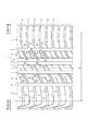
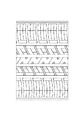
また、比較例タイヤ1は図2に示した従来タイプの点対称のトレッドパターンを有するものであり、従って、タイヤ赤道線を挟んで二分されるそれぞれのトレッド踏面のネガティブ率は同じであり、剛性も同じであるものである。
Below, the example of the tire concerning the present invention is described.
As a test tire, a size of 175/70 R13 and one type of example tire 1 and one type of comparative tire 1 were prepared. Example tire 1 has the tread pattern shown in FIG.
Moreover, the comparative example tire 1 has a tread pattern of the conventional type shown in FIG. 2, and therefore, the negative rate of each tread surface divided by the tire equator line is the same, and rigidity Is the same.
供試タイヤをサイズ5Jのリムにリム組すると共に、充填空気圧を220kPaとして試験車両に、ネガティブキャンバ角を2度として装着し、2名乗車に相当する荷重を付加した状態で、ドライ操縦性については、乾燥条件のアスファルト路面で実車走行を行い、直進安定性やレーンチェンジ性、コーナリング性についてのフィーリングの指数評価を行い、ウェット操縦性については水深10mmのアスファルト路面にて、直進安定性やレーンチェンジ性、コーナリング性についてのフィーリングの指数評価を行った。また、ウェット制動性能については、水深10mmのアスファルト路面において速度80km/hから制動試験を行いその制動距離を指数評価した。またハイドロプレーニング性については、水深10mmのアスファルト路面において、各種速度で制動試験を行い、ハイドロプレーニング現象が発生する限界速度をそれぞれ測定し、それらを指数評価した。なお、指数評価は比較例タイヤ1をコントロールとし、数値が大きいほど良好であることを示す。 About the dry maneuverability, with the test tire mounted on a rim of size 5J, with a filling air pressure of 220 kPa, a negative camber angle of 2 degrees, and a load equivalent to 2 passengers. The vehicle runs on dry asphalt roads, evaluates the index of feeling of straight running stability, lane changeability, cornering, and wet maneuverability on asphalt roads with a water depth of 10 mm. The index evaluation of feeling about lane change and cornering was performed. As for wet braking performance, a braking test was performed from a speed of 80 km / h on an asphalt road surface having a water depth of 10 mm, and the braking distance was evaluated as an index. Regarding the hydroplaning property, braking tests were performed at various speeds on asphalt road surfaces with a water depth of 10 mm, the critical speeds at which hydroplaning phenomenon occurred were measured, and these were indexed. In addition, index evaluation makes comparative example tire 1 control, and shows that it is so favorable that a numerical value is large.
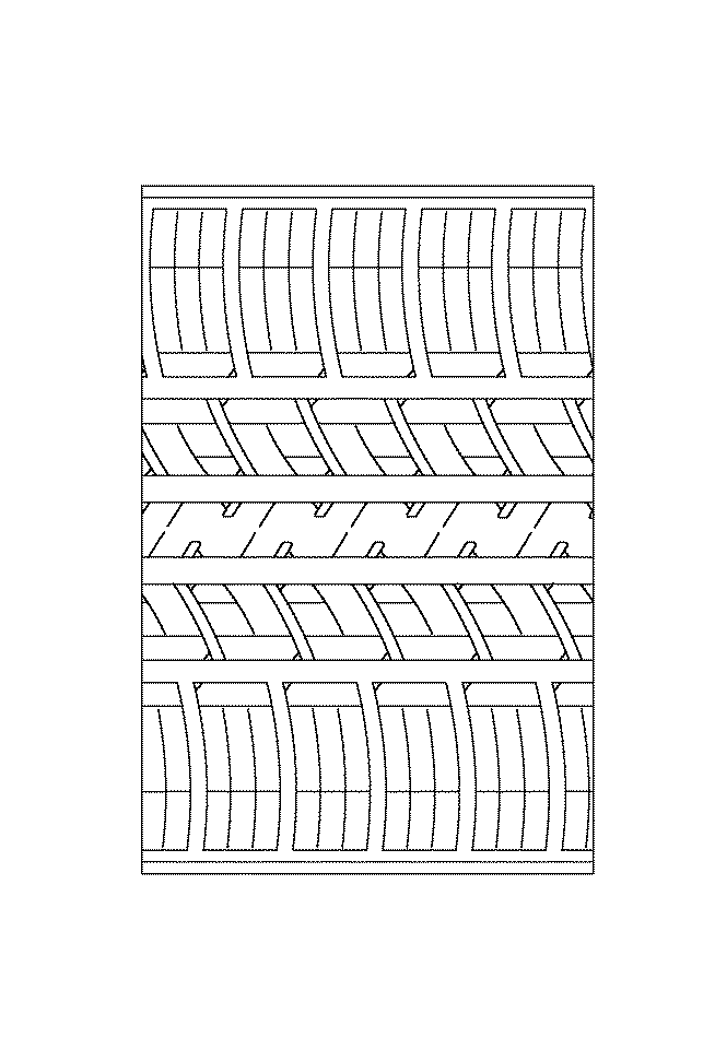
表1に示すところによれば、実施例タイヤ1は、ドライ操縦性能、ウェット操縦性能、ハイドロプレーニング性能の測定項目において、従来のパターンである比較例タイヤ1の性能を上回っていることが分かる。 According to the results shown in Table 1, it can be seen that the example tire 1 exceeds the performance of the comparative example tire 1 which is the conventional pattern in the measurement items of the dry handling performance, the wet handling performance, and the hydroplaning performance.
本発明は、ネガティブキャンバ角を付与した状態において、操舵性と加減速性能との両立を図った空気入りタイヤなどに適用して効果的なものである。 The present invention is effective when applied to a pneumatic tire or the like that achieves both steering performance and acceleration / deceleration performance in a state where a negative camber angle is provided.
1 トレッド踏面部
2 センター周溝(装着外側)
3 センター周溝(装着内側)
4 センターリブ
5 サイド周溝(装着外側)
6 サイド周溝(装着内側)
7 ショルダー陸部(装着内側)
8 中間陸部(装着内側)
9 中間陸部(装着外側)
10 ショルダー陸部(装着外側)
11 横溝
12 ブロック
13 行止り横溝
14 サイプ
15 横溝
16 ブロック
17 サイプ
18 行止り傾斜溝
19 行止り周方向溝
20 周方向サイプ
21 リブ
22 ブロック
23 サイプ
24 傾斜溝
25 サイプ
26 ブロック
27 サイプ
28 サイプ
29 傾斜溝
1 Tread surface 2 Center groove (outside)
3 Center circumferential groove (inside of mounting)
4
6 Side groove (inside of mounting)
7 Shoulder land (installed inside)
8 Middle land (installed inside)
9 Middle land (outside)
10 Shoulder land (outside)
11
Claims (3)
タイヤ赤道線より、装着内側部分のネガティブ率を、装着外側部分のネガティブ率に比して2〜5%大きくし、
装着内側のショルダー陸部に、トレッド踏面端とサイド周溝とを連通する複数の横溝を設けるとともに、隣り合う横溝のほぼ中央に位置して、トレッド踏面端からサイド周溝に向けて伸びてサイド周溝の手前で終了する複数の行止り横溝と、行止り横溝の終了端とサイド周溝とを連通する複数のサイプとを設け、
装着外側のショルダー陸部に、サイド周溝とトレッド踏面端とを連通する複数の横溝を設けるとともに、隣り合う横溝のほぼ中央に位置して、トレッド踏面端とサイド周溝とを連通するサイプを設け、
装着内側の中間陸部に、サイド周溝からセンター周溝に向かって延びてセンター周溝の手前で終了する複数の行止り傾斜溝を設けるとともに、行止り傾斜溝の終了端からトレッド周方向に向かって延び、隣接する傾斜溝の手前で終了する行止り周方向溝を設け、この行止り周方向溝の終了端と、隣接する行止り傾斜溝の終了端とを連通する周方向サイプを設け、隣り合う行止り傾斜溝のほぼ中央に位置して行止り周方向溝もしくは周方向サイプとサイド周溝とを連通するサイプを設け、
装着外側の中間陸部に、サイド周溝とセンター周溝とを連通する複数の傾斜溝を設け、隣り合う傾斜溝のほぼ中央に位置して、サイド周溝からセンター周溝に向かって延びてセンター周溝の手前で終了する複数のサイプを設けてなる空気入りタイヤ。 A tread tread surface portion is provided with a pair of center circumferential grooves that are located across the tire equator line and extend continuously in the tread circumferential direction, and continuously between the center circumferential groove and the tread tread edge in the tread circumferential direction. A vehicle is formed by providing a pair of extending side circumferential grooves, defining a shoulder land portion between the side circumferential groove and the tread tread edge, and defining an intermediate land portion between the center circumferential groove and the side circumferential groove. A pneumatic tire having an asymmetric pattern with a specified mounting posture,
From the tire equator line, the negative rate of the inner part of the wearing is 2-5% larger than the negative rate of the outer part of the wearing,
A plurality of lateral grooves that connect the tread tread edge and the side circumferential groove are provided on the shoulder land portion on the inner side of the mounting, and are located at the approximate center of the adjacent lateral grooves and extend from the tread tread edge toward the side circumferential groove. A plurality of dead-end lateral grooves that end before the circumferential groove, and a plurality of sipes that communicate the end edge of the dead-end lateral groove and the side circumferential groove,
A plurality of lateral grooves that connect the side circumferential groove and the tread tread surface end are provided on the shoulder land portion on the outer side of the wearing, and a sipe that communicates between the tread tread surface end and the side circumferential groove is located substantially at the center of the adjacent lateral groove. Provided,
A plurality of dead-falling grooves extending from the side circumferential groove toward the central circumferential groove and ending before the central circumferential groove are provided in the intermediate land portion on the inner side of the mounting, and in the tread circumferential direction from the end of the dead-falling groove. A dead end circumferential groove extending toward the end of the adjacent inclined groove is provided, and a circumferential sipe is provided to communicate the end end of the dead end circumferential groove with the end end of the adjacent stop inclined groove. , Provided in the middle of the adjacent dead end inclined groove, a dead end circumferential groove or a sipe communicating the circumferential sipe and the side circumferential groove,
A plurality of inclined grooves that connect the side circumferential groove and the center circumferential groove are provided in the intermediate land portion on the outer side of the mounting, and are located at substantially the center of the adjacent inclined grooves and extend from the side circumferential groove toward the center circumferential groove. A pneumatic tire provided with a plurality of sipes ending before the center circumferential groove.
タイヤ幅方向に延びるサイプの、幅を0.5〜1.1mmとし、深さをセンターおよびサイド周溝の深さの0.6〜0.9倍としてなる請求項1に記載の空気入りタイヤ。 The width of the dead end lateral groove is 2 to 6 mm, the depth is 0.6 to 0.9 times the depth of the center and side circumferential grooves,
The pneumatic tire according to claim 1, wherein the sipe extending in the tire width direction has a width of 0.5 to 1.1 mm and a depth of 0.6 to 0.9 times the depth of the center and side circumferential grooves. .
Priority Applications (1)
| Application Number | Priority Date | Filing Date | Title |
|---|---|---|---|
| JP2004119821A JP4373264B2 (en) | 2004-04-15 | 2004-04-15 | Pneumatic tire |
Applications Claiming Priority (1)
| Application Number | Priority Date | Filing Date | Title |
|---|---|---|---|
| JP2004119821A JP4373264B2 (en) | 2004-04-15 | 2004-04-15 | Pneumatic tire |
Publications (2)
| Publication Number | Publication Date |
|---|---|
| JP2005297880A true JP2005297880A (en) | 2005-10-27 |
| JP4373264B2 JP4373264B2 (en) | 2009-11-25 |
Family
ID=35329936
Family Applications (1)
| Application Number | Title | Priority Date | Filing Date |
|---|---|---|---|
| JP2004119821A Expired - Fee Related JP4373264B2 (en) | 2004-04-15 | 2004-04-15 | Pneumatic tire |
Country Status (1)
| Country | Link |
|---|---|
| JP (1) | JP4373264B2 (en) |
Cited By (20)
| Publication number | Priority date | Publication date | Assignee | Title |
|---|---|---|---|---|
| JP2007237816A (en) * | 2006-03-06 | 2007-09-20 | Bridgestone Corp | Pneumatic tire |
| JP2007237805A (en) * | 2006-03-06 | 2007-09-20 | Bridgestone Corp | Pneumatic tire |
| WO2008146851A1 (en) * | 2007-05-28 | 2008-12-04 | Bridgestone Corporation | Tire |
| WO2009157268A1 (en) * | 2008-06-25 | 2009-12-30 | 株式会社ブリヂストン | Tire |
| WO2010061631A1 (en) * | 2008-11-27 | 2010-06-03 | 株式会社ブリヂストン | Tire |
| WO2010061544A1 (en) * | 2008-11-27 | 2010-06-03 | 株式会社ブリヂストン | Tire |
| CN101758745A (en) * | 2008-12-22 | 2010-06-30 | 住友橡胶工业株式会社 | Pneumatic tire with sipes |
| WO2010122805A1 (en) * | 2009-04-22 | 2010-10-28 | 株式会社ブリヂストン | Pnuematic tire |
| JP2011042328A (en) * | 2009-08-24 | 2011-03-03 | Sumitomo Rubber Ind Ltd | Pneumatic tire |
| US8306387B2 (en) | 2008-07-24 | 2012-11-06 | Panasonic Corporation | Play back apparatus, playback method and program for playing back 3D video |
| US8522845B2 (en) | 2007-10-23 | 2013-09-03 | The Yokohama Rubber Co., Ltd. | Pneumatic tire |
| KR20160030525A (en) * | 2013-07-16 | 2016-03-18 | 피렐리 타이어 소시에떼 퍼 아찌오니 | Car tyre |
| JP2016137748A (en) * | 2015-01-26 | 2016-08-04 | 住友ゴム工業株式会社 | Pneumatic tire |
| CN105936197A (en) * | 2015-03-04 | 2016-09-14 | 住友橡胶工业株式会社 | Pneumatic tyre |
| CN108621710A (en) * | 2017-03-15 | 2018-10-09 | 住友橡胶工业株式会社 | Pneumatic tire |
| CN108944273A (en) * | 2012-03-15 | 2018-12-07 | 住友橡胶工业株式会社 | Pneumatic tire |
| JP2019051896A (en) * | 2017-09-19 | 2019-04-04 | 住友ゴム工業株式会社 | tire |
| JP2020131759A (en) * | 2019-02-13 | 2020-08-31 | 住友ゴム工業株式会社 | tire |
| CN113348096A (en) * | 2019-01-23 | 2021-09-03 | 横滨橡胶株式会社 | Pneumatic tire |
| JP2023078991A (en) * | 2021-11-26 | 2023-06-07 | 住友ゴム工業株式会社 | tire |
-
2004
- 2004-04-15 JP JP2004119821A patent/JP4373264B2/en not_active Expired - Fee Related
Cited By (49)
| Publication number | Priority date | Publication date | Assignee | Title |
|---|---|---|---|---|
| JP2007237805A (en) * | 2006-03-06 | 2007-09-20 | Bridgestone Corp | Pneumatic tire |
| JP2007237816A (en) * | 2006-03-06 | 2007-09-20 | Bridgestone Corp | Pneumatic tire |
| WO2008146851A1 (en) * | 2007-05-28 | 2008-12-04 | Bridgestone Corporation | Tire |
| US8851130B2 (en) | 2007-05-28 | 2014-10-07 | Bridgestone Corporation | Tire having rows of block land portions, lateral grooves and at least three circumferential grooves |
| US8522845B2 (en) | 2007-10-23 | 2013-09-03 | The Yokohama Rubber Co., Ltd. | Pneumatic tire |
| WO2009157268A1 (en) * | 2008-06-25 | 2009-12-30 | 株式会社ブリヂストン | Tire |
| JP5364706B2 (en) * | 2008-06-25 | 2013-12-11 | 株式会社ブリヂストン | tire |
| CN102105315B (en) * | 2008-06-25 | 2013-10-30 | 株式会社普利司通 | Tire |
| US9308779B2 (en) | 2008-06-25 | 2016-04-12 | Bridgestone Corporation | Tire |
| US8306387B2 (en) | 2008-07-24 | 2012-11-06 | Panasonic Corporation | Play back apparatus, playback method and program for playing back 3D video |
| WO2010061631A1 (en) * | 2008-11-27 | 2010-06-03 | 株式会社ブリヂストン | Tire |
| US8863796B2 (en) | 2008-11-27 | 2014-10-21 | Bridgestone Corporation | Tire |
| CN102227321A (en) * | 2008-11-27 | 2011-10-26 | 株式会社普利司通 | Tire |
| CN102227322A (en) * | 2008-11-27 | 2011-10-26 | 株式会社普利司通 | tire |
| US9073391B2 (en) | 2008-11-27 | 2015-07-07 | Bridgestone Corporation | Tire |
| CN102227321B (en) * | 2008-11-27 | 2015-07-08 | 株式会社普利司通 | Tire |
| JP2010125977A (en) * | 2008-11-27 | 2010-06-10 | Bridgestone Corp | Tire |
| WO2010061544A1 (en) * | 2008-11-27 | 2010-06-03 | 株式会社ブリヂストン | Tire |
| JP5497662B2 (en) * | 2008-11-27 | 2014-05-21 | 株式会社ブリヂストン | tire |
| KR101581960B1 (en) * | 2008-12-22 | 2015-12-31 | 스미토모 고무 고교 가부시키가이샤 | Pneumatic tire |
| CN101758745A (en) * | 2008-12-22 | 2010-06-30 | 住友橡胶工业株式会社 | Pneumatic tire with sipes |
| KR20100073983A (en) * | 2008-12-22 | 2010-07-01 | 스미토모 고무 고교 가부시키가이샤 | Pneumatic tire |
| JP2010143532A (en) * | 2008-12-22 | 2010-07-01 | Sumitomo Rubber Ind Ltd | Pneumatic tire |
| WO2010122805A1 (en) * | 2009-04-22 | 2010-10-28 | 株式会社ブリヂストン | Pnuematic tire |
| JP2011042328A (en) * | 2009-08-24 | 2011-03-03 | Sumitomo Rubber Ind Ltd | Pneumatic tire |
| US8640750B2 (en) | 2009-08-24 | 2014-02-04 | Sumitomo Rubber Industries, Ltd. | Pneumatic tire with tread having shoulder blocks and crown blocks |
| CN108944274A (en) * | 2012-03-15 | 2018-12-07 | 住友橡胶工业株式会社 | Pneumatic tire |
| CN108944273A (en) * | 2012-03-15 | 2018-12-07 | 住友橡胶工业株式会社 | Pneumatic tire |
| CN108944274B (en) * | 2012-03-15 | 2020-09-04 | 住友橡胶工业株式会社 | Pneumatic tires |
| CN108944273B (en) * | 2012-03-15 | 2021-02-12 | 住友橡胶工业株式会社 | Pneumatic tire |
| KR20160030525A (en) * | 2013-07-16 | 2016-03-18 | 피렐리 타이어 소시에떼 퍼 아찌오니 | Car tyre |
| JP2016525043A (en) * | 2013-07-16 | 2016-08-22 | ピレリ・タイヤ・ソチエタ・ペル・アツィオーニ | Tires for vehicles |
| EP3892477A1 (en) | 2013-07-16 | 2021-10-13 | Pirelli Tyre S.p.A. | Car tyre |
| US10933696B2 (en) | 2013-07-16 | 2021-03-02 | Pirelli Tyre S.P.A. | Car tyre |
| KR102220161B1 (en) | 2013-07-16 | 2021-02-25 | 피렐리 타이어 소시에떼 퍼 아찌오니 | Car tyre |
| EP3022069B1 (en) * | 2013-07-16 | 2019-12-04 | Pirelli Tyre S.p.A. | Car tyre |
| EP3616944A1 (en) | 2013-07-16 | 2020-03-04 | Pirelli Tyre S.p.A. | Car tyre |
| EP3616943A1 (en) | 2013-07-16 | 2020-03-04 | Pirelli Tyre S.p.A. | Car tyre |
| JP2016137748A (en) * | 2015-01-26 | 2016-08-04 | 住友ゴム工業株式会社 | Pneumatic tire |
| CN105936197B (en) * | 2015-03-04 | 2019-06-07 | 住友橡胶工业株式会社 | Pneumatic tire |
| CN105936197A (en) * | 2015-03-04 | 2016-09-14 | 住友橡胶工业株式会社 | Pneumatic tyre |
| CN108621710A (en) * | 2017-03-15 | 2018-10-09 | 住友橡胶工业株式会社 | Pneumatic tire |
| JP2019051896A (en) * | 2017-09-19 | 2019-04-04 | 住友ゴム工業株式会社 | tire |
| CN113348096A (en) * | 2019-01-23 | 2021-09-03 | 横滨橡胶株式会社 | Pneumatic tire |
| CN113348096B (en) * | 2019-01-23 | 2023-09-05 | 横滨橡胶株式会社 | pneumatic tire |
| JP2020131759A (en) * | 2019-02-13 | 2020-08-31 | 住友ゴム工業株式会社 | tire |
| JP7183848B2 (en) | 2019-02-13 | 2022-12-06 | 住友ゴム工業株式会社 | tire |
| JP2023078991A (en) * | 2021-11-26 | 2023-06-07 | 住友ゴム工業株式会社 | tire |
| JP7779108B2 (en) | 2021-11-26 | 2025-12-03 | 住友ゴム工業株式会社 | tire |
Also Published As
| Publication number | Publication date |
|---|---|
| JP4373264B2 (en) | 2009-11-25 |
Similar Documents
| Publication | Publication Date | Title |
|---|---|---|
| JP4373264B2 (en) | Pneumatic tire | |
| CN101195326B (en) | Pneumatic tire | |
| JP5993407B2 (en) | Pneumatic tire | |
| US9889708B2 (en) | Pneumatic tire | |
| US10286732B2 (en) | Tire | |
| US9150056B2 (en) | Pneumatic tire | |
| US8857483B2 (en) | Studless tire | |
| JP5265554B2 (en) | Pneumatic tire | |
| US9085201B2 (en) | Pneumatic tire | |
| JP6674414B2 (en) | Pneumatic tire | |
| KR101475670B1 (en) | Pneumatic tire | |
| EP3127715B1 (en) | Pneumatic tire | |
| CN107757260B (en) | Tyre for vehicle wheels | |
| CN109501524B (en) | Tyre for vehicle wheels | |
| US20170274708A1 (en) | Pneumatic Tire | |
| WO2017187734A1 (en) | Pneumatic tire | |
| KR20180025808A (en) | Pneumatic tire | |
| WO2015182022A1 (en) | Pneumatic tire | |
| JP7163136B2 (en) | pneumatic tire | |
| JP2014080112A (en) | Pneumatic tire | |
| JP4122179B2 (en) | Pneumatic tire | |
| JP2015077941A (en) | Pneumatic tire | |
| JP2010254049A (en) | Pneumatic tire | |
| JP6420694B2 (en) | Pneumatic tire | |
| JP2005263180A (en) | Pneumatic tire |
Legal Events
| Date | Code | Title | Description |
|---|---|---|---|
| A621 | Written request for application examination |
Free format text: JAPANESE INTERMEDIATE CODE: A621 Effective date: 20061226 |
|
| A977 | Report on retrieval |
Free format text: JAPANESE INTERMEDIATE CODE: A971007 Effective date: 20090727 |
|
| TRDD | Decision of grant or rejection written | ||
| A01 | Written decision to grant a patent or to grant a registration (utility model) |
Free format text: JAPANESE INTERMEDIATE CODE: A01 Effective date: 20090804 |
|
| A01 | Written decision to grant a patent or to grant a registration (utility model) |
Free format text: JAPANESE INTERMEDIATE CODE: A01 |
|
| A61 | First payment of annual fees (during grant procedure) |
Free format text: JAPANESE INTERMEDIATE CODE: A61 Effective date: 20090903 |
|
| FPAY | Renewal fee payment (event date is renewal date of database) |
Free format text: PAYMENT UNTIL: 20120911 Year of fee payment: 3 |
|
| R150 | Certificate of patent or registration of utility model |
Free format text: JAPANESE INTERMEDIATE CODE: R150 |
|
| LAPS | Cancellation because of no payment of annual fees |