JP2010142428A - Photographing apparatus, photographing method, program and recording medium - Google Patents
Photographing apparatus, photographing method, program and recording medium Download PDFInfo
- Publication number
- JP2010142428A JP2010142428A JP2008322956A JP2008322956A JP2010142428A JP 2010142428 A JP2010142428 A JP 2010142428A JP 2008322956 A JP2008322956 A JP 2008322956A JP 2008322956 A JP2008322956 A JP 2008322956A JP 2010142428 A JP2010142428 A JP 2010142428A
- Authority
- JP
- Japan
- Prior art keywords
- image
- subject
- schematic image
- photographing
- schematic
- Prior art date
- Legal status (The legal status is an assumption and is not a legal conclusion. Google has not performed a legal analysis and makes no representation as to the accuracy of the status listed.)
- Ceased
Links
Images

Classifications
-
- A—HUMAN NECESSITIES
- A61—MEDICAL OR VETERINARY SCIENCE; HYGIENE
- A61B—DIAGNOSIS; SURGERY; IDENTIFICATION
- A61B3/00—Apparatus for testing the eyes; Instruments for examining the eyes
- A61B3/10—Objective types, i.e. instruments for examining the eyes independent of the patients' perceptions or reactions
- A61B3/12—Objective types, i.e. instruments for examining the eyes independent of the patients' perceptions or reactions for looking at the eye fundus, e.g. ophthalmoscopes
-
- A—HUMAN NECESSITIES
- A61—MEDICAL OR VETERINARY SCIENCE; HYGIENE
- A61B—DIAGNOSIS; SURGERY; IDENTIFICATION
- A61B3/00—Apparatus for testing the eyes; Instruments for examining the eyes
- A61B3/10—Objective types, i.e. instruments for examining the eyes independent of the patients' perceptions or reactions
- A61B3/14—Arrangements specially adapted for eye photography
- A61B3/15—Arrangements specially adapted for eye photography with means for aligning, spacing or blocking spurious reflection ; with means for relaxing
- A61B3/152—Arrangements specially adapted for eye photography with means for aligning, spacing or blocking spurious reflection ; with means for relaxing for aligning
-
- A—HUMAN NECESSITIES
- A61—MEDICAL OR VETERINARY SCIENCE; HYGIENE
- A61B—DIAGNOSIS; SURGERY; IDENTIFICATION
- A61B3/00—Apparatus for testing the eyes; Instruments for examining the eyes
- A61B3/10—Objective types, i.e. instruments for examining the eyes independent of the patients' perceptions or reactions
- A61B3/102—Objective types, i.e. instruments for examining the eyes independent of the patients' perceptions or reactions for optical coherence tomography [OCT]
Landscapes
- Life Sciences & Earth Sciences (AREA)
- Health & Medical Sciences (AREA)
- Medical Informatics (AREA)
- Biophysics (AREA)
- Ophthalmology & Optometry (AREA)
- Engineering & Computer Science (AREA)
- Biomedical Technology (AREA)
- Heart & Thoracic Surgery (AREA)
- Physics & Mathematics (AREA)
- Molecular Biology (AREA)
- Surgery (AREA)
- Animal Behavior & Ethology (AREA)
- General Health & Medical Sciences (AREA)
- Public Health (AREA)
- Veterinary Medicine (AREA)
- Eye Examination Apparatus (AREA)
Abstract
【課題】 経時変化を伴う被写体について、比較観察に適した同一部位の詳細画像を精度よく容易に撮影するための技術を提供する。
【解決手段】 経時変化する被写体を撮影する撮影装置は、被写体の概略画像を取得する第1取得手段と、概略画像において経時変化が他の部分よりも小さい基準部分を決定する決定手段と、詳細な撮影を行うべき被写体の撮影位置を第1の概略画像において設定する設定手段と、第1の概略画像の被写体と同一の被写体について第2の概略画像が取得された場合、該第1の概略画像の基準部分と該第2の概略画像の基準部分とに基づいて、当該第2の概略画像を該第1の概略画像に対して位置合わせする位置合わせ手段と、位置合わせされた第2の概略画像の第1の概略画像の撮影位置に対応する位置について、被写体の詳細な撮影画像を取得する第2取得手段と、を備える。
【選択図】 図9PROBLEM TO BE SOLVED: To provide a technique for easily and accurately photographing a detailed image of the same part suitable for comparative observation with respect to a subject with a change with time.
An imaging apparatus that captures a subject that changes with time includes a first acquisition unit that acquires a schematic image of the subject, a determination unit that determines a reference portion in which the temporal change is smaller than other portions in the schematic image, and details Setting means for setting the shooting position of the subject to be shot in the first schematic image, and when the second schematic image is acquired for the same subject as the subject of the first schematic image, the first schematic Alignment means for aligning the second schematic image with respect to the first schematic image based on the reference portion of the image and the reference portion of the second schematic image; Second acquisition means for acquiring a detailed captured image of the subject at a position corresponding to the shooting position of the first schematic image of the schematic image.
[Selection] Figure 9
Description
本発明は撮影装置及び撮影方法、プログラム、記録媒体に関する。 The present invention relates to a photographing apparatus, a photographing method, a program, and a recording medium.
近年、眼部の検査は、生活習慣病や失明原因の上位を占める各種疾病の早期診断に効果的なことから、注目を集めている。中でも、眼科医院等において使用する眼底カメラや、光干渉断層計(OCT:Optical Coherence Tomography)などの眼部の断層像取得装置は、疾病の状態を客観的尺度で定量化することが可能である。このため、これらの装置は疾病の診断をより的確に行うのに有用であると期待されている。 In recent years, eye examinations have attracted attention because they are effective in early diagnosis of various diseases that account for the top causes of lifestyle-related diseases and blindness. Among them, a fundus camera used in an ophthalmic clinic or the like, and an ophthalmic tomogram acquisition device such as an optical coherence tomography (OCT) can quantify the state of a disease on an objective scale. . For this reason, these devices are expected to be useful for more accurately diagnosing diseases.
一般的なOCTでは、撮影者が断面画像の撮影パラメータ(例えば、対象部位、撮像範囲、詳細度、走査方法など)を決定し、その撮影パラメータに基づいて眼部の局所領域の断面画像の撮影が行われる。断面画像は眼底部の狭い領域の断面のみを投影した画像であるため、眼底全体を観察するには、膨大な枚数の断面画像を撮影することとなる。しかし、検診などとは異なり、特定部位の疾患や術後の経過観察においては、より少ない枚数の画像の比較が診断に適していることから、時間が経過しても同じ部位を撮影できることが望ましい。 In general OCT, a photographer determines imaging parameters (for example, a target region, imaging range, level of detail, scanning method, etc.) of a cross-sectional image, and captures a cross-sectional image of a local region of the eye based on the imaging parameters. Is done. Since the cross-sectional image is an image obtained by projecting only a cross section of a narrow region of the fundus, an enormous number of cross-sectional images are taken to observe the entire fundus. However, unlike medical examinations, it is desirable to compare the smaller number of images for diagnosis in diseases at specific sites and follow-up after surgery. .
一方、眼球の病状の進行度の観察や、薬品の処方や術後の経過観察等のような同じ患者の同一部位の状態の変化を観察する場合には、長期間にわたり、間隔をあけて同一部位の断面画像の撮影が必要となる。さらに、より少ない枚数で、広範囲、かつ、高精細な画像で病変部を捉えた同一部位の断面画像を比較することが経時変化の比較には適している。 On the other hand, when observing changes in the same part of the same patient, such as observation of the degree of progression of eyeballs, prescription of drugs, follow-up after surgery, etc., it is the same over a long period of time. It is necessary to take a cross-sectional image of the part. Furthermore, comparing cross-sectional images of the same site in which a lesion area is captured with a wide range and a high-definition image with a smaller number of images is suitable for comparing changes over time.
従来の技術によれば、例えば、初期のOCT装置では、診断に用いる断面画像の位置を指定できないために、指定された走査領域内を一定の間隔で複数枚撮影し、病変の診断に必要な断面画像を選択して診断に用いていた。近年では、追尾機構を備えた眼科撮影装置が考案されており、例えば、眼底カメラの画像を表示した画面上で断面画像の撮影位置の指定をユーザから受け付けて、断面画像の撮影を行う。あるいは、眼底カメラや走査型レーザー検眼鏡(SLO:Scanning Laser Ophthalmoscope)を用いて撮像される眼球の眼底部や前眼部の画像上の位置情報を用いて断面画像の撮影を行う構成も知られている。これらの構成は後述する特許文献1〜4に開示されている。 According to the conventional technique, for example, since the position of the cross-sectional image used for diagnosis cannot be specified in the initial OCT apparatus, a plurality of images are taken at a predetermined interval in the specified scanning region, and are necessary for the diagnosis of the lesion. A cross-sectional image was selected and used for diagnosis. In recent years, an ophthalmologic photographing apparatus having a tracking mechanism has been devised. For example, a cross-sectional image is photographed by receiving designation of a photographing position of a cross-sectional image from a user on a screen displaying an image of a fundus camera. Or the structure which image | photographs a cross-sectional image using the positional information on the image of the fundus part of an eyeball and an anterior eye part imaged using a fundus camera or a scanning laser ophthalmoscope (SLO) is also known. ing. These configurations are disclosed in Patent Documents 1 to 4 described later.
また、眼球は注視状態においても個視微動などの視線の動きがあり、被検者の眼の位置を固定することが困難である。このため、装置の座標系において同一座標に静止させて眼を撮影することは難しく、断面画像の撮影位置を記録するには眼の特徴を基準とすることが必要である。しかし、眼球の形状や特徴自体は経時変化する場合が多く、特に診断の必要があるケースでは病変による経時変化が発生しやすい。このため、眼の特徴を利用した位置情報の精度を維持することは従来の技術では困難であり、経時変化が予想され経過観察が必要な状況では、同一部位の断面画像を精度よく撮影する技術の必要性が高まっている。 In addition, the eyeball has a line-of-sight movement such as individual fine movement even in a gaze state, and it is difficult to fix the position of the eye of the subject. For this reason, it is difficult to image the eye while still at the same coordinate in the coordinate system of the apparatus, and it is necessary to use the eye feature as a reference in order to record the imaging position of the cross-sectional image. However, the shape and characteristics of the eyeball themselves often change over time, and changes with time are likely to occur due to lesions, particularly in cases where diagnosis is necessary. For this reason, it is difficult for conventional techniques to maintain the accuracy of positional information using eye features, and in situations where changes over time are expected and follow-up is required, a technique for accurately capturing cross-sectional images of the same part The need for is increasing.
撮像者による断層像の撮像を支援する技術として、特許文献1には、眼底カメラによる正面画像上においてOCTによる断面画像の撮像範囲を指示するユーザインタフェースに関する構成が開示されている。また、特許文献2には、SLOによる広域像上においてOCTによる断層像の撮像範囲を指定するユーザインタフェースに関する構成が開示されている。特許文献1や特許文献2の構成によれば、ユーザが眼底の正面画像の様子を参照しながら断層像の撮像範囲を決定することができる。 As a technique for assisting an imager to capture a tomographic image, Patent Document 1 discloses a configuration related to a user interface that instructs an imaging range of a cross-sectional image by OCT on a front image by a fundus camera. Patent Document 2 discloses a configuration related to a user interface for designating an imaging range of a tomographic image by OCT on a wide area image by SLO. According to the configurations of Patent Literature 1 and Patent Literature 2, the user can determine the imaging range of the tomographic image while referring to the state of the fundus front image.
また、撮影装置の各設定情報を断面画像ごとに記録しておく構成が特許文献3に述べられている。さらに、眼底画像の位置情報を記録し、断面画像の撮影に用いる構成が特許文献4に開示されている。
傷病の進行状況や治療効果を診断するため、医療分野では経過観察が広く行われている。経過観察は、長期間にわたり複数回の検査を行い、各調査結果を比較して診断を行うものである。特に、眼の疾患の診断には、患部等の注目部位の画像を取得し、その画像を比較することによって注目部位の経時的な変化を確認する作業が頻繁に行われる。 Follow-up is widely performed in the medical field in order to diagnose the progress of the wound and the therapeutic effect. In follow-up observation, a plurality of tests are performed over a long period of time, and each survey result is compared to make a diagnosis. In particular, for diagnosing an eye disease, an operation of acquiring an image of a site of interest such as an affected area and comparing the images with time is frequently performed.
このような画像を用いた経過観察のためには、同一部位の画像を複数回取得する必要がある。しかしながら、従来の眼底観察装置を用いた眼底検査においては、同一部位の画像を取得することは困難であった。異なる検査日時において、同じ患者の同一部位の画像を取得することは、固視微動等のため、撮影中に眼球の位置、向きを同一位置に固定することはできない。そのため、撮影装置の制御手順や設定値が同じであっても同一部位を撮影できるとは限らない。 For follow-up observation using such an image, it is necessary to acquire an image of the same part a plurality of times. However, in a fundus examination using a conventional fundus observation device, it is difficult to acquire an image of the same part. Acquiring images of the same part of the same patient at different examination dates and times cannot fix the position and orientation of the eyeball at the same position during imaging due to fixation movement and the like. Therefore, even if the control procedure and setting values of the imaging apparatus are the same, it is not always possible to image the same part.
さらに、OCTによって取得した眼底の断層画像を用いた診断では、撮像範囲が大きく、かつ、高精細な断面画像を撮影して過去の断面画像と比較観察することが、診断に適している。ところが、通常、このような断面画像の撮影には時間を要するため、走査領域をずらしながら複数枚の連続撮影を行う手法では、比較観察に適した同一位置の断面画像を得ることは難しい。このため、過去の断層画像撮影位置と同一部位が必ずしも撮影できず、所望の断面画像を得るまでには冗長な撮影数を必要としていた。そのため、撮影作業時間の増加、冗長な撮影画像からの選別、医師の指示による再撮影等、様々な点で、医師や撮影技師の作業の手間を増加させていた。 Further, in diagnosis using a fundus tomographic image acquired by OCT, it is suitable for diagnosis to take a high-definition cross-sectional image having a large imaging range and to compare with a past cross-sectional image. However, since it usually takes time to shoot such a cross-sectional image, it is difficult to obtain a cross-sectional image at the same position suitable for comparative observation by a method of performing continuous shooting of a plurality of sheets while shifting the scanning region. For this reason, the same part as the past tomographic image photographing position cannot always be photographed, and a redundant number of photographing is required to obtain a desired cross-sectional image. For this reason, the work of the doctor and the imaging engineer has been increased in various points such as an increase in the shooting time, selection from redundant shot images, and re-shooting according to the doctor's instructions.
さらに、経時変化を観察した診断が必要となる疾患の場合、長期間に渡り撮影を繰り返すことから、眼球、眼の血管、患部組織の形状や特徴が変化するケースが多く、経時変化を観察すべき疾患ほど、同一部位の撮影が難しいという課題があった。すなわち、たとえ、眼の断面画像の撮影位置を記録しても、現在の被検者の眼の形状や特徴が変化するため、これらを基準とした位置情報が、過去の撮影位置を正しく再現できなかった。 Furthermore, in the case of diseases that require diagnosis by observing changes over time, the shape and characteristics of the eyeball, blood vessels of the eye, and affected tissue are often changed because the imaging is repeated over a long period of time. There was a problem that imaging of the same part was more difficult as the disease should be. In other words, even if the photographing position of the cross-sectional image of the eye is recorded, the current shape and characteristics of the subject's eyes change, so position information based on these can correctly reproduce the past photographing position. There wasn't.
本発明は上記課題に鑑みなされたものであり、経時変化を伴う被写体について、比較観察に適した同一部位の詳細画像を精度よく容易に撮影するための技術を提供することを目的とする。 The present invention has been made in view of the above problems, and an object of the present invention is to provide a technique for easily and accurately photographing a detailed image of the same part suitable for comparative observation with respect to a subject that changes with time.
上記目的を達成するため、本発明による撮影装置は以下の構成を備える。即ち、
経時変化する被写体を撮影する撮影装置であって、
前記被写体の概略画像を取得する第1取得手段と、
前記概略画像において経時変化が他の部分よりも小さい基準部分を決定する決定手段と、
詳細な撮影を行うべき前記被写体の撮影位置を第1の前記概略画像において設定する設定手段と、
前記第1の概略画像の被写体と同一の被写体について第2の前記概略画像が取得された場合、該第1の概略画像の前記基準部分と該第2の概略画像の前記基準部分とに基づいて、当該第2の概略画像を該第1の概略画像に対して位置合わせする位置合わせ手段と、
前記位置合わせされた第2の概略画像の前記第1の概略画像の前記撮影位置に対応する位置について、前記被写体の詳細な撮影画像を取得する第2取得手段と、
を備える。
In order to achieve the above object, a photographing apparatus according to the present invention comprises the following arrangement. That is,
A photographing device for photographing a subject that changes over time,
First acquisition means for acquiring a schematic image of the subject;
Determining means for determining a reference portion whose temporal change is smaller in the schematic image than other portions;
Setting means for setting the shooting position of the subject to be subjected to detailed shooting in the first schematic image;
When the second schematic image is acquired for the same subject as the subject of the first schematic image, based on the reference portion of the first schematic image and the reference portion of the second schematic image Positioning means for aligning the second schematic image with respect to the first schematic image;
Second acquisition means for acquiring a detailed captured image of the subject for a position corresponding to the shooting position of the first schematic image of the aligned second schematic image;
Is provided.
また、本発明による撮影方法は以下の構成を有する。即ち、
経時変化する被写体を撮影する撮影装置における撮影方法であって、
前記被写体の概略画像を取得する第1取得工程と、
前記概略画像において経時変化が他の部分よりも小さい基準部分を決定する決定工程と、
詳細な撮影を行うべき前記被写体の撮影位置を第1の前記概略画像において設定する設定工程と、
前記第1の概略画像の被写体と同一の被写体について第2の前記概略画像が取得された場合、該第1の概略画像の前記基準部分と該第2の概略画像の前記基準部分とに基づいて、当該第2の概略画像を該第1の概略画像に対して位置合わせする位置合わせ工程と、
前記位置合わせされた第2の概略画像の前記第1の概略画像の前記撮影位置に対応する位置について、前記被写体の詳細な撮影画像を取得する第2取得工程と、
を有する。
The photographing method according to the present invention has the following configuration. That is,
A photographing method in a photographing device for photographing a subject that changes over time,
A first acquisition step of acquiring a schematic image of the subject;
A determination step of determining a reference portion whose temporal change is smaller than other portions in the schematic image;
A setting step of setting a shooting position of the subject to be subjected to detailed shooting in the first schematic image;
When the second schematic image is acquired for the same subject as the subject of the first schematic image, based on the reference portion of the first schematic image and the reference portion of the second schematic image An alignment step of aligning the second schematic image with respect to the first schematic image;
A second acquisition step of acquiring a detailed captured image of the subject for a position corresponding to the imaging position of the first schematic image of the aligned second schematic image;
Have
本発明によれば、経時変化を伴う被写体について、比較観察に適した同一部位の詳細画像を精度よく容易に撮影するための技術を提供することができる。 ADVANTAGE OF THE INVENTION According to this invention, the technique for image | photographing the detailed image of the same site | part suitable for comparative observation easily with sufficient precision can be provided about the photographic subject accompanying a time-dependent change.
以下、添付図面を参照して本発明に係る実施の形態を詳細に説明する。ただし、この実施の形態に記載されている構成要素はあくまでも例示であり、本発明の範囲をそれらのみに限定する趣旨のものではない。また、本実施の形態で説明されている特徴の組み合わせの全てが発明の解決手段に必須のものとは限らない。 Embodiments according to the present invention will be described below in detail with reference to the accompanying drawings. However, the constituent elements described in this embodiment are merely examples, and are not intended to limit the scope of the present invention only to them. In addition, not all the combinations of features described in the present embodiment are essential for the solving means of the invention.
(撮影装置)
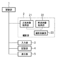
図1は本実施形態に係る撮影装置の機能ブロックを示す図である。図1を用いて本実施形態に係る撮影装置の機能構成を説明する。
(Shooting device)
FIG. 1 is a diagram showing functional blocks of the photographing apparatus according to the present embodiment. A functional configuration of the photographing apparatus according to the present embodiment will be described with reference to FIG.
図1の制御部1は、撮影装置およびシステム全体の制御や後述する基準決定処理のような画像処理等の制御を行う。制御部1は、一般的なCPU(Central Processing Unit)等で実現することができる。撮影部2は、被検眼の追尾や位置合わせを行いながら、眼底画像と断面画像の撮影を行い、撮影した画像を画像メモリに格納する。 The control unit 1 in FIG. 1 performs control such as image processing such as control of the entire photographing apparatus and system and reference determination processing described later. The control unit 1 can be realized by a general CPU (Central Processing Unit) or the like. The imaging unit 2 captures a fundus image and a cross-sectional image while tracking and positioning the eye to be examined, and stores the captured image in an image memory.
入力部3は、撮影装置の操作・設定の入力、後述する状態情報の入力や、本実施形態に係るユーザーの各操作入力を受け付ける。入力部3は、例えば、撮影装置上に用意されたテンキーや、ボタン等、あるいは、PCのキーボード、ポインティングデバイス等による操作入力を受け付ける。さらに、本実施形態に係る状態情報や、正面画像、断面画像、位置情報に加えて、撮影装置の動作や処理手順の制御に用いる設定データ等が保存されたファイルやメモリ、通信による入力も入力部3は受け付ける。
The
記憶部4は、撮影部2により撮影された眼底画像および断層画像、状態情報、眼底画像中の断層画像撮影位置を示す位置情報等の撮影に係る各種情報を記録する。記憶部4は、例えば、メモリやハードディスクのように撮影装置内の記憶装置で構成してもよいし、DVDのような媒体メディアであってもよいし、患者のカルテシステムのようなデータベースを用いて構成してもよい。 The storage unit 4 records various information related to imaging such as a fundus image and a tomographic image captured by the imaging unit 2, state information, and position information indicating a tomographic image capturing position in the fundus image. The storage unit 4 may be configured by a storage device in the photographing apparatus such as a memory or a hard disk, or may be a medium medium such as a DVD, or a database such as a patient chart system is used. May be configured.
表示部5は、後述する撮影処理の手順に従って撮影者に必要な表示を行う。例えば、撮影処理の手順に関する情報、撮影装置の状態や処理状況等の制御部1の制御情報をはじめ、撮影用のパラメータや、撮影時の正面画像、断面画像や被検者の眼の情報等のような撮影部2に関する情報、画像の表示を行う。表示部5は液晶パネルや有機ELパネルなどの表示デバイスを用いて実現することができる。
The
また、表示部5は、入力部3が入力を受け付けた撮影者の入力操作用の画面表示や、入力内容、操作状況を示す情報の表示も行うことができる。さらに表示部5は、記録部4により記録された過去の眼底画像、断層画像、状態情報、位置情報のような、保存されている画像、設定情報等の表示も行うことができる。
The
(撮影部)
撮影部2は、正面画像取得部21と断面画像取得部22、並びに撮影制御部23を備える。撮影制御部23は、正面画像取得部21と断面画像取得部22の動作を制御する機能要素である。以下、正面画像取得部21と断面画像取得部22について詳細に説明する。
(Shooting part)
The imaging unit 2 includes a front
●正面画像取得部21
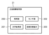
正面画像取得部21は、例えば、眼底画像、あるいは前眼部の画像のような正面画像を取得するための眼底カメラやSLOなどによって実現される。正面画像取得部21は、被写体の概略画像を取得する第1取得手段として機能する。図2は、正面画像取得部21が眼底カメラである場合の機能構成例を示すブロック図である。正面画像取得部21は眼の正面画像を撮影して取得する装置であり、例えば、照明部200、光学処理部201、センサ部202、固視目標提示部203等を備える。
● Front
The front
照明部200は、眼底照明系のユニットや前眼部の照明用光源のユニットなどの照明系ユニットを備える。光学処理部201は、光学系ユニットを備え光学処理を行う機能要素である。光学系ユニットとしては、例えば、被検眼に対抗する対物レンズ、孔部に撮影絞りを有する孔あきミラー、光路方向に移動してピントを調整するフォーカスレンズ、撮影レンズ、観察時には光路内にあり撮影時には光路から離脱する切替ミラーなどが含まれる。
The
センサ部202は、眼底画像を撮影する撮影用センサユニットや観察用センサユニットのセンサユニットを備える。固視目標提示部203は、固視目標を表示するための、複数個のセルがマトリクス状に配置された液晶素子とバックライトを備え、個々のセルの透過、不透過を設定することができる。
The
次に、正面画像取得部21における撮影操作の一例を説明する。撮影者は、まず、前眼部観察を行い、入力部3から操作を行って、被検眼と光学処理部201内の対物レンズの概略位置合わせを行う。この状態で照明部200の前眼部照明用光源が点灯され、照明された前眼部像は、光学処理部201内でのレンズ、ミラーで制御され、センサユニット202内の観察用センサユニットの撮像面に結像する。そして、観察用センサユニットで光電変換された前眼部画像が表示部5に表示される。撮影者が手動で調整する場合は、撮影者は、この前眼部画像を見ながら、撮影部2を搭載したステージを移動させることにより被検眼に対する眼底カメラの位置を調整し、撮影する。
Next, an example of the photographing operation in the front
一方、眼底画像を表示する場合は、照明部200内の眼底照明系ユニットから、光学処理部201内の孔あきミラー部で反射させ、対物レンズを介して被検眼の瞳孔を通して眼底を照明する。照明された眼底像は、光学処理部201内の対物レンズやミラーを透過し、センサ部202内の観察用センサユニットの撮像面に結像する。この結像画像は観察用センサユニットで光電変換されて、眼底画像が表示部5に表示される。なお、撮影者は眼底画像を見ながら撮影部2を搭載したステージを移動させて被検眼に対する眼底カメラの位置を調整し、撮影することもできる。
On the other hand, when displaying a fundus image, the fundus illumination system unit in the
●断面画像取得部22
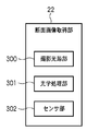
次に、断面画像取得部22の構成について図3を参照して説明する。図3はOCT装置で実現した場合の断面画像取得部22の機能構成例を示すブロック図である。
● Section
Next, the configuration of the cross-sectional
断面画像取得部22は、眼部の断層のような断面画像を撮影する装置であり、例えばタイムドメイン方式のOCTやフーリエドメイン方式のOCTで構成することができる。断面画像取得部22は、被写体の詳細な撮影画像を取得する第2取得手段として機能する。図3の断面画像取得部22は、タイムドメインOCTである場合の機能構成例を示している。
The cross-sectional
図3において、撮影光源部300は、例えば、OCT装置の低コヒーレンス光源のような断面画像撮影用の光源である。光学処理部301は、参照ミラー、ガルバノミラ‐、ミラー駆動機構等を備えた光学処理を行う光学処理系のユニット群で構成された機能要素である。センサ部302は、例えば、CCDのような受光素子であり、各ユニットに必要な制御は撮影制御部23が行う。
In FIG. 3, an imaging
次に、断面画像取得部22を用いた断面画像取得の操作手順の一例を説明する。撮影者は、はじめに、撮影のためのパラメータの設定等の入力を行った後、断面像の撮影を入力部3から指示する。撮影のためのパラメータには、例えば、断面画像の取得部位、断面画像の空間的範囲、スキャンライン間隔などの詳細度、走査順や走査方向といった走査法を指示するパラメータが含まれる。入力部3が入力を受け付けた設定と撮影指示は、制御部1を介して撮影部2に通知される。
Next, an example of an operation procedure for obtaining a cross-sectional image using the cross-sectional
撮影部2の断面画像取得部22は、撮影制御部23の制御のもと、撮影光源部300の低コヒーレンス光源から照射された光の被検眼の眼底部からの反射光をセンサ部302の受光素子で受光して、眼部の断面画像を撮影する。撮影が終了し、取得された断面画像は撮影制御部23内のメモリに格納され、制御部1を介して、表示部5に表示される。
Under the control of the imaging control unit 23, the cross-sectional
このとき、撮影制御部23は、入力部からの1つの撮影指示に対し、断面画像を1枚取得することも、あるいは、設定情報に応じて複数枚の断層画像を取得することも可能である。また、複数の断面画像を連続的に撮影しながら、撮影制御部23が取捨選択して取得画像を決定することも可能である。 At this time, the imaging control unit 23 can acquire one cross-sectional image in response to one imaging instruction from the input unit, or can acquire a plurality of tomographic images according to the setting information. . It is also possible for the imaging control unit 23 to select and determine an acquired image while continuously capturing a plurality of cross-sectional images.
ここで、初期の眼底カメラでは、撮影者がステージを移動させて撮影する方法が一般的であった。また、OCT装置も、手動で撮影パラメータを調整し、走査領域を決定して撮影する方法が一般的であった。しかし、近年では、前述の前眼部画像や眼底画像の特徴や画像処理や、眼、視線検出センサなどの手段を用いて眼の動きを追尾する機能を備えた撮影装置が考案されている。本実施形態では、撮影部2がこのような追尾機能を有する撮影装置である場合を想定するが、追尾機能を有しなくても構わない。さらに正面画像取得部の眼底カメラ以外の例として、例えば、眼、走査型レーザー検眼鏡(SLO:Scanning Laser Ophthalmoscope)であってもよい。さらに、SLOと眼底カメラの両方を備える構成であってもよい。 Here, in an early fundus camera, a method in which a photographer moves a stage to shoot is common. In addition, the OCT apparatus also generally has a method in which imaging parameters are manually adjusted, a scanning region is determined, and imaging is performed. However, in recent years, an imaging apparatus has been devised that has the function of tracking the movement of the eye using features such as the above-described anterior eye part image and fundus image, image processing, and eye and eye detection sensors. In the present embodiment, it is assumed that the photographing unit 2 is a photographing device having such a tracking function, but the photographing unit 2 may not have the tracking function. Furthermore, as an example other than the fundus camera of the front image acquisition unit, for example, an eye or a scanning laser ophthalmoscope (SLO) may be used. Furthermore, the structure provided with both SLO and a fundus camera may be sufficient.
また、撮影部2で用いられる撮影パラメータ等の設定値は、必ずしも撮影者による入力が必要ではなく、撮影装置が撮影を自動制御することも可能である。例えば、断面画像取得部22内で保持する設定の初期値を用いたり、断面画像の深さ方向をオートゲインで適切な範囲に設定したりして撮影してもよい。あるいは、追尾機構を用いて被検眼の向き等を追尾し、所望の向きの眼底画像の撮影や、指定された位置の断面画像を撮影することもできる。
Further, the setting values such as the shooting parameters used in the shooting unit 2 do not necessarily need to be input by the photographer, and the shooting apparatus can automatically control the shooting. For example, the image may be shot by using an initial value of the setting held in the cross-sectional
このような撮影パラメータ等の設定値は、撮影制御部23が正面画像取得部21と断面画像取得部22の個々の情報に応じて、各設定値を変更したり撮影のタイミングを制御することもできる。すなわち、正面画像取得部21で得られる被検眼の情報や追尾機構を用いながら断面画像22で用いる設定値を設定したり、撮影のタイミングを制御することも可能である。また逆に、断面画像取得部22の情報を用いて正面画像取得部21の設定変更や撮影の制御を行うこともできる。
For such setting values such as imaging parameters, the imaging control unit 23 may change each setting value or control the timing of imaging according to the individual information of the front
(撮影処理)
図4は、本実施形態に係る撮影処理の手順を示すフローチャートである。本実施形態では、現在の診断に用いると共に今後継続的な経過観察が必要な部位の撮影であって、経時変化による病変の影響を受けずに精度よく同じ部位の撮影を繰り返す必要がある撮影の処理を説明する。本実施形態では、特に、眼球の黄斑部に異常があり、黄斑部周辺の形状や特徴が経時変化により変化するような場合について、図4を参照して説明する。なお、撮影処理で取得される正面画像は、第1の概略画像(第1の前記概略画像)の一例である。
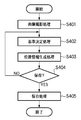
(Shooting process)
FIG. 4 is a flowchart showing the procedure of the photographing process according to the present embodiment. In the present embodiment, imaging of a part that is used for the current diagnosis and needs to be continuously monitored in the future, and it is necessary to repeat imaging of the same part accurately without being affected by a lesion due to a change over time. Processing will be described. In the present embodiment, in particular, a case where there is an abnormality in the macular portion of the eyeball and the shape and characteristics around the macular portion change with time will be described with reference to FIG. Note that the front image acquired by the imaging process is an example of a first schematic image (first schematic image).
本実施形態の撮影処理は、入力部3で被検眼の撮影指示が入力されると開始される。図4の各処理ステップは制御部1を実現するCPUの制御に基づいて実行される。
The imaging process of this embodiment is started when an imaging instruction for the eye to be examined is input through the
●画像撮影処理(S401)
S401では、被検眼の眼底画像とOCTの断面画像を撮影し、表示部5に表示する(画像撮影処理)。被検眼の眼底画像と断面画像は同時に撮影されることが望ましいが、断面画像の撮影位置を眼底画像に精度よく関連づけられれば、必ずしも同時に撮影する必要はない。また、断面画像撮影と同時にSLOを撮影し、SLOの画像と眼底カメラの眼底画像の位置合わせを行って、眼底カメラの眼底画像に断面画像の撮影位置を関連づけても構わない。
Image capturing process (S401)
In S401, the fundus image of the eye to be examined and the cross-sectional image of the OCT are captured and displayed on the display unit 5 (image capturing process). Although it is desirable that the fundus image and the cross-sectional image of the eye to be inspected be simultaneously photographed, it is not always necessary to photograph simultaneously if the photographing position of the cross-sectional image is accurately associated with the fundus image. Further, the SLO may be taken simultaneously with the cross-sectional image photographing, the SLO image and the fundus image of the fundus camera may be aligned, and the photographing position of the cross-sectional image may be associated with the fundus image of the fundus camera.
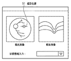
なお、撮影直後に断面画像の撮影位置情報を記録する。この撮影位置情報は、このステップでは、後のステップで眼底画像上の位置情報に変換できる位置情報(例えば、撮影装置の操作位置の座標値等)であればどのような位置情報でもよい。このようにして、詳細な撮影を行うべき被写体の撮影位置が概略画像(正面画像)において設定される。撮影した眼底画像、及び断面画像は、例えば図5で示すような画面で表示部5が表示する。図5は、表示部5が表示する画面の一例を示す模式図である。
Note that the shooting position information of the cross-sectional image is recorded immediately after shooting. This imaging position information may be any position information in this step as long as it is position information (for example, coordinate values of the operation position of the imaging apparatus) that can be converted into position information on the fundus image in a later step. In this way, the shooting position of the subject to be subjected to detailed shooting is set in the schematic image (front image). The captured fundus image and cross-sectional image are displayed by the
●基準決定処理(S402)
次に、S402では基準決定処理を行う。基準決定処理(S402)では、ユーザから入力された後述の状態情報を用いて正面画像上での断面画像の撮影位置を決定するための基準点を抽出すべく、特徴の抽出領域を決定する(抽出領域の決定)。そして、この抽出領域内の特徴を用いて、後述する位置情報生成処理(S403)において断面画像撮影位置の位置情報を生成する際に用いる基準点を決定する(基準点の決定)。なお、本実施形態では、概略画像(正面画像)における経時変化が他の部分よりも小さい基準部分が点(基準点)である場合について説明するが、後述するように、線や一定の範囲を占める領域でもよい。
● Standard decision processing (S402)
Next, in S402, a reference determination process is performed. In the reference determination process (S402), a feature extraction region is determined in order to extract a reference point for determining the photographing position of the cross-sectional image on the front image using state information (described later) input by the user ( Determination of extraction area). Then, using the feature in the extraction region, a reference point used when generating position information of the cross-sectional image photographing position in position information generation processing (S403) described later is determined (determination of reference point). In the present embodiment, a case is described where the reference portion in which the temporal change in the schematic image (front image) is smaller than other portions is a point (reference point). However, as described later, a line or a certain range is used. It may be an area occupied.
(1)抽出領域の決定
この抽出領域は、状態情報をもとに眼底画像内の病変の影響が小さいことが予想される領域である。本実施形態では、抽出領域は、まず眼底画像領域内で病変の可能性の高い領域を非抽出領域として決定し、眼底画像領域内の非抽出領域を除いた領域として決定する。ただし、抽出領域をじかに指定するようにしてもよい。
(1) Determination of extraction region This extraction region is a region where the influence of a lesion in the fundus image is expected to be small based on state information. In the present embodiment, the extraction area is first determined as a non-extraction area in the fundus image area as a non-extraction area, and is determined as an area excluding the non-extraction area in the fundus image area. However, the extraction area may be designated directly.
S402で実行する基準点決定処理は、撮影者が被検眼の眼の状態を識別できる情報、すなわち、被検体の状態情報が入力部3から入力されたことに応じて実行を開始する。ここで、状態情報は被写体の状態を示す情報である。本実施形態では、被写体は患者の患部であるため、状態情報としては、例えば、眼底画像上の特定部位の疾患を識別できる、病名(例:黄斑浮腫)や、特定部位に異常があることを示す所見の情報を用いることができる。また、被検体の特定部位に経時変化が発生している、または、発生すると予測される領域を特定できるような、被検体の状態を示す情報でもよい。あるいは、状態情報は、疾患の進行度や患部の名称でもよい。
The reference point determination process executed in S <b> 402 starts in response to information that allows the photographer to identify the eye state of the subject's eye, i.e., the subject state information, is input from the
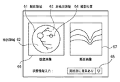
このように、被検体の状態を識別できる情報であれば、状態情報に特に制約はない。また、状態情報の入力も、任意の手法を用いて行うことができる。本実施形態では黄斑部に異常がある点を基準点として入力する例を説明する。この場合、状態情報の入力は、例えば、表示部5に表示される画面上から、あらかじめ用意された黄斑部に異常がある項目をユーザが選択して入力するような手法で実現することができる。図6は、このような状態情報の入力画面の一例を示す図である。
As described above, the state information is not particularly limited as long as it is information that can identify the state of the subject. In addition, input of state information can be performed using any method. In this embodiment, an example will be described in which a point having an abnormality in the macula is input as a reference point. In this case, the input of the state information can be realized, for example, by a method in which the user selects and inputs an item having an abnormality in a previously prepared macular part from the screen displayed on the
図6では、GUI(Graphical User Interface)上で状態情報の内容を選択するための入力画面の一例を示している(65)。制御部1が識別できるならば、本実施形態に係る撮影処理の手順を適用することができる。例えば、テキストの文章入力や、病名などの特定のキーワードの入力、さらには、各状態情報を複数個入力してもよい。このようにして、ユーザインタフェースを介してユーザから指定された状態情報を入力することができる。 FIG. 6 shows an example of an input screen for selecting the contents of status information on a GUI (Graphical User Interface) (65). If the control unit 1 can be identified, the procedure of the imaging process according to the present embodiment can be applied. For example, text text input, input of specific keywords such as disease names, and a plurality of pieces of status information may be input. In this way, state information designated by the user can be input via the user interface.
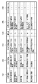
本実施形態では、被写体の状態を示す状態情報と、経時変化が他の部分よりも大きい領域との対応関係を示す対応情報を参照テーブルとして記憶装置に記憶しておく。そして、状態情報が入力されると参照テーブルを読み出す読出処理を行って、入力された状態情報に対応する領域を正面画像から除いた部分を基準部分を抽出する抽出領域として決定する。図7は、制御部1が参照するテーブルの一例を示す図である。本実施形態に係る撮影装置で使用される情報は、任意のキーワードの登録や、各状態情報の優先度、複数の状態情報を適用する場合のルール等を撮影者が事前に編集して参照テーブルとして登録される。 In the present embodiment, the state information indicating the state of the subject and the correspondence information indicating the correspondence relationship between the area where the change over time is larger than that of other portions are stored in the storage device as a reference table. Then, when the state information is input, a read process for reading the reference table is performed, and a portion obtained by removing the region corresponding to the input state information from the front image is determined as an extraction region for extracting the reference portion. FIG. 7 is a diagram illustrating an example of a table referred to by the control unit 1. The information used in the image capturing apparatus according to the present embodiment is a reference table in which a photographer edits in advance the registration of arbitrary keywords, the priority of each state information, rules for applying a plurality of state information, and the like. Registered as
図7において、701は状態情報であり、患部の状態に関する情報が記載されている。702は非抽出領域であり、病変の可能性が高く基準点を抽出するのがふさわしくない領域の情報が記載されている。703は非抽出領域情報であり、非抽出領域を特定するための情報が記載されている。704は優先度であり、複数の非抽出領域の特定方法が適用できる状態情報がある場合に非抽出領域の特定方法を適用する優先度をA,B,C,・・・のランクで示している。705、706は基準点抽出方法1、2であり、抽出領域から基準点を抽出する方法が記載されている。
In FIG. 7,
状態情報の入力画面には、図6で示した例のように撮影者が非抽出領域を把握できるように眼底画像66と断面画像67を表示してもよい。図6において、眼底画像66中の眼底領域61は眼底画像中の眼底の領域である。非抽出領域63は、基準を抽出しない領域として算出された非抽出領域である。抽出領域62は、眼底領域61から非抽出領域63を除いた領域であり、図7で示した参照テーブルで既定されている方法により基準点とする特徴を抽出する領域である。また、撮影位置64は断面画像の撮影位置である。本実施形態では、撮影位置64の断面画像67がGUI画面上に表示される。
On the state information input screen, a
非抽出領域の決定は、本実施形態のように黄斑部に異常がある場合には、眼底画像から黄斑部を抽出し、あらかじめ制御部1の保持している参照テーブルを参照して、基準とする特徴の非抽出領域を決定することで実行できる。非抽出領域の決定に必要なパラメータや設定情報は、図7で一例を示した参照テーブルのような情報を、制御部1があらかじめ保持していればよい。あるいは、例えば図5のようなGUI画面上で、ユーザがポインティングデバイス等で任意の領域を指定し、指定された領域を非抽出領域として入力するようにして、非抽出領域を決定してもよい。 In the determination of the non-extraction region, when there is an abnormality in the macular portion as in the present embodiment, the macular portion is extracted from the fundus image, and the reference and the reference table held in advance by the control unit 1 are referred to. This can be executed by determining the non-extraction region of the feature to be. For the parameters and setting information necessary for determining the non-extraction area, the control unit 1 may hold information such as the reference table shown in FIG. 7 in advance. Alternatively, for example, on the GUI screen as shown in FIG. 5, the user may designate an arbitrary area with a pointing device or the like and input the designated area as a non-extraction area to determine the non-extraction area. .
非抽出領域は眼底画像とは区別できるように表示することが望ましいが、撮影者がGUI上から非抽出領域に任意の色を指定して着色できるようにしてもよい。また、複数の非抽出領域を同時に表示する場合や、特徴を抽出する領域ごとの優先度が異なる場合に、それぞれを色分けして表示してもよい。 Although it is desirable to display the non-extraction area so that it can be distinguished from the fundus image, the photographer may be able to specify and color the non-extraction area from the GUI. In addition, when a plurality of non-extracted areas are displayed simultaneously or when the priorities of the areas from which features are extracted are different, they may be displayed in different colors.
なお、図6、図7では、まず非抽出領域を決定してから眼底画像の残りの領域を抽出領域として決定する場合を例示したが、抽出領域を最初から決定しても構わない。すなわち、参照テーブルと表示画面に関して、図7の例では、非抽出領域を扱う場合が記述されていた。また、図6では、領域指定や領域表示について、まず非抽出領域を決定する例を示した。しかし、本実施形態においては、これら参照テーブル内の設定データや、GUIの操作や表示について、非抽出領域に限るものではなく、抽出領域を扱うようにしても同じように実行可能である。 6 and 7 illustrate the case where the non-extraction region is first determined and then the remaining region of the fundus image is determined as the extraction region. However, the extraction region may be determined from the beginning. That is, with respect to the reference table and the display screen, the example of FIG. 7 describes a case where a non-extraction area is handled. FIG. 6 shows an example in which a non-extraction area is first determined for area designation and area display. However, in the present embodiment, the setting data in these reference tables, GUI operation and display are not limited to non-extraction areas, and can be executed in the same way even when handling extraction areas.
(2)基準点の決定
抽出領域からの特徴抽出においては、例えば、眼底画像中の黄斑部や神経乳頭の中心や血管の形状や分岐点などにおける様々な情報を特徴として抽出することができる。これらの特徴の画素の輝度値の最大値、平均値、中央値、分散、標準偏差、閾値以上の点の数やその割合等を特徴として抽出することができる。更に、小領域に分割し、濃度ヒストグラム、平均濃度、濃度分散値、コントラスト等の濃度を特徴として抽出してもよい。
(2) Determination of the reference point In the feature extraction from the extraction region, for example, various information on the macular portion, the center of the nerve papilla, the shape of the blood vessel, the branch point, etc. in the fundus image can be extracted as the feature. The maximum value, the average value, the median value, the variance, the standard deviation, the number of points above the threshold, the ratio thereof, and the like can be extracted as the features. Further, the image may be divided into small regions, and density such as density histogram, average density, density dispersion value, and contrast may be extracted as features.
一例として、黄斑部を除いた領域を抽出領域とし、眼底画像内の血管を抽出しその分岐点を基準とする場合の特徴抽出の一例を示す。はじめに、眼底画像中から、黄斑部の領域を非抽出領域として決定する。黄斑部の領域は、黄斑部を示す所定の色の範囲の画素が占める領域や、所定の色の範囲の画素の領域を内部に含む領域として決定することができる。このとき、眼底画像中のノイズなどから、複数箇所に領域の候補がある場合には、ユーザーによる眼底画像上のおおよその位置の指定と、画素の色による判定の併用するなど、領域の決定方法も様々な方法を使用できる。黄斑部を含む非抽出領域が決定されるご眼底画像の領域と非抽出領域の情報から、抽出領域が決定される。 As an example, an example of feature extraction in a case where a region excluding the macular portion is set as an extraction region, a blood vessel in a fundus image is extracted, and a branch point thereof is used as a reference is shown. First, the macular region is determined as a non-extraction region from the fundus image. The area of the macular part can be determined as an area occupied by pixels in a predetermined color range indicating the macular part or an area including a pixel area in the predetermined color range. At this time, if there are region candidates at a plurality of locations due to noise in the fundus image, the region determination method such as the approximate designation of the position on the fundus image by the user and the determination based on the pixel color are used in combination. Various methods can also be used. The extraction area is determined from the information of the fundus image area and the non-extraction area where the non-extraction area including the macula is determined.
次に、抽出領域内から血管をあらわす所定の色の範囲の画素を抽出する。このとき、より健康で経時変化に強い血管の色を所定の閾値を用いた範囲で判定し、必ずしも血管をあらわす色すべてではなく、特徴として抽出すべき血管の色を示す画素を抽出する。そして、抽出された血管の分岐点から、例えば、神経乳頭と血管の境界上の点や、神経乳頭から血管の伸びる向きや、何番目の分岐点であるか等のルールから基準点とすべき特徴を決定することができる。これらの特徴の選定方法は撮影時と再撮影時で、同じ選定方法を用いることができれば、どのような方法であっても実施することができる。 Next, pixels in a predetermined color range representing a blood vessel are extracted from the extraction region. At this time, the color of the blood vessel that is healthier and more resistant to changes with time is determined in a range using a predetermined threshold value, and pixels that indicate the color of the blood vessel to be extracted as features are extracted, not necessarily all the colors that represent the blood vessels. Then, from the branch point of the extracted blood vessel, for example, it should be a reference point based on rules such as a point on the boundary between the nerve papilla and the blood vessel, the direction in which the blood vessel extends from the nerve papilla, and the number of the branch point. Features can be determined. These characteristics can be selected by any method as long as the same selection method can be used at the time of shooting and at the time of re-shooting.
このようにして決定された基準点を用いて、例えば2点の基準点を決定したときは眼底画像上で座標系を決定し、断面画像の撮影位置を基準点を元にした座標系の位置として相対的な位置情報を生成することができる。また、これらの特徴は本実施形態における再撮影処理の手順において、過去の眼底画像と被検眼の眼底画像との位置合わせにも用いることができる。なお、基準決定処理の開始は、状態情報の入力終了と同時に自動的に開始してもよいし、入力部3から基準決定処理の開始を指定されたことに応じて開始してもよい。
For example, when two reference points are determined using the reference points determined in this way, the coordinate system is determined on the fundus image, and the position of the coordinate system based on the reference point is determined from the photographing position of the cross-sectional image. Relative position information can be generated. These features can also be used for alignment of the past fundus image and the fundus image of the eye to be examined in the procedure of the re-imaging process in the present embodiment. The start of the reference determination process may be automatically started simultaneously with the end of the input of the state information, or may be started when the start of the reference determination process is designated from the
●位置情報生成処理(S403)
S403では位置情報生成処理を実行し、断面画像の撮影位置を、基準決定処理(S402)で決定された基準点に対する眼底画像上の撮影位置情報に変換し、保存用の位置情報を生成する。ここで、位置情報は、正面画像に対して設定された撮影位置の基準部分に対する相対位置を示す情報とすることができる。撮影位置情報はS402で決定された基準点に基づく位置情報であればどのような位置情報でもよい。その一例としては、S402で決定された2点の基準点を通る第1の直線と基準点のうちの1点で第1の直線と直交するようなXY平面を定義し、断面画像の撮影位置の始点の座標値と終点の座標値を記録するようにすることができる。さらに複数の断面画像の撮影位置も記録できるようにする場合は、前述の始点と終点の座標値に加えて、断面画像の向きや枚数、断面画像の長さあたりのピクセル数を示す解像度、撮影のスライス間隔等の情報を合わせて位置情報に加えるようにしてもよい。
Position information generation process (S403)
In S403, position information generation processing is executed to convert the photographing position of the cross-sectional image into photographing position information on the fundus image with respect to the reference point determined in the reference determination processing (S402), and generate position information for storage. Here, the position information can be information indicating a relative position with respect to the reference portion of the shooting position set for the front image. The shooting position information may be any position information as long as it is position information based on the reference point determined in S402. As an example, an XY plane that is orthogonal to the first straight line at one of the reference lines and the first straight line passing through the two reference points determined in S402 is defined, and the photographing position of the cross-sectional image is defined. The coordinate value of the start point and the coordinate value of the end point can be recorded. In addition, in order to be able to record the shooting position of multiple cross-sectional images, in addition to the coordinate values of the start point and end point described above, the resolution and shooting indicating the direction and number of cross-sectional images, the number of pixels per length of the cross-sectional image Information such as the slice interval may be added to the position information.
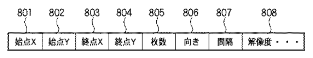
図8は撮影位置情報として記録する情報の項目例を示す図である。図8において、801は断面画像の撮影位置の始点のX座標であり、802はそのY座標である。803は断面画像の撮影位置の終点のX座標であり、804はそのY座標である。805は撮影する断面画像の枚数であり、806は撮影する断面画像の向きである。807は一定間隔をあけた複数の断面画像を一度に撮影する場合の撮影位置の間隔であり、808は断面画像の解像度である。例えば、撮影する断面画像が1枚の場合は、始点と終点が断面画像の位置を指定する線分の両端となる。また、複数の断面画像を一定間隔で撮影する場合には、始点と終点は、複数の断面画像群が占める矩形の対角をなす2点として矩形領域を示し、その矩形領域内を断面画像の枚数805、又は、撮影位置の間隔807の情報で断面画像の撮影位置を指定できる。
FIG. 8 is a diagram showing an example of information items recorded as shooting position information. In FIG. 8, 801 is the X coordinate of the starting point of the photographing position of the cross-sectional image, and 802 is the Y coordinate.
また、これらの撮影位置情報を簡略化するために、図8の座標値以外の情報を制御部1内部に撮影装置の撮影位置のルールとしてあらかじめ用意しておいてもよい。この場合、そのルールを識別する識別子を保存対象の位置情報に加えるだけで、撮影位置を簡単に設定することができる。 Further, in order to simplify the shooting position information, information other than the coordinate values in FIG. 8 may be prepared in advance in the control unit 1 as a shooting position rule of the shooting apparatus. In this case, the shooting position can be easily set simply by adding an identifier for identifying the rule to the position information to be stored.
さらに、あらかじめ、状態情報ごとに、これらの撮影位置のルールを割り当てられる場合がある。例えば、特定の疾患は特定の位置に発症することが予め分かっている場合や検診等の目的で撮影位置が決まっている場合がある。このような場合には、図7で示した参照テーブルの1項目として、撮影ルールを割り当てておくことで、撮影位置の座標を詳細に記述する必要がなく、生成する位置情報の情報量を軽減することも可能である。 Furthermore, these shooting position rules may be assigned in advance for each state information. For example, there is a case where it is known in advance that a specific disease develops at a specific position, or a photographing position is determined for the purpose of medical examination or the like. In such a case, by assigning a shooting rule as one item of the reference table shown in FIG. 7, it is not necessary to describe the coordinates of the shooting position in detail, and the amount of position information to be generated is reduced. It is also possible to do.
●保存指示の受け付け(S404)
位置情報生成処理(S403)が終了すると、S404において、撮影者はこの情報で保存してよいかを確認して、入力部3から保存(保持)を指示する。ここで、撮影者が保存を指示しなかった場合(S404でNO)、S402に戻って基準点決定処理から、再度、処理をやり直すことも可能である。撮影条件に関する情報、例えば、撮影装置にあらかじめプリセットされている図7の参照テーブルのような設定情報や、撮影ルールのような既存の設定情報をそのまま使うか判断する場合はここで行う。既存の設定値とルールによりS402、S403で決定された非抽出領域(抽出領域でもよい)や基準点や位置情報を表示部5の表示で確認後、ユーザは、任意の領域指定や設定変更を行い、再度S402から処理を行うように指示を行う。
● Reception of save instruction (S404)
When the position information generation process (S403) ends, in S404, the photographer confirms whether or not the information can be saved, and instructs the
●保存処理(S405)
S404において、撮影者が入力部3より保存指示を行った場合(S404でYES)は、S405に進んで保存処理を実行する。S405の保存処理では、記憶部4に、S401で撮影した眼底画像とS402で入力された眼の状態情報、S403で生成された位置情報を、S401で撮影した断面画像と関連づけて保存(保持)する。ここで、断面画像との関連づけは、後に診断で用いる各断面画像の撮影位置情報として識別可能であれば、どのような手法を用いて行っても構わない。例えば、同じ値の識別子をファイル名に付加してもよいし、断面画像ごとに作成されるフォルダ内にまとめて保存してもよい。
● Save processing (S405)
In S404, when the photographer gives a save instruction from the input unit 3 (YES in S404), the process proceeds to S405 to execute a save process. In the storage process in S405, the fundus image captured in S401, the eye state information input in S402, and the position information generated in S403 are stored (stored) in the storage unit 4 in association with the cross-sectional image captured in S401. To do. Here, associating with a cross-sectional image may be performed using any method as long as it can be identified as photographing position information of each cross-sectional image used in diagnosis later. For example, an identifier having the same value may be added to the file name, or may be stored together in a folder created for each cross-sectional image.
また、撮影装置内のハードディスクのような記憶装置以外に、ネットワークを介して他の計算機の記憶装置に記憶したり、DVD−RAM等の記録メディアに書き出すようにしてS405保存処理を行っても構わない。さらに、データベースサーバや電子カルテシステム等の1データとして登録するように構成することもできる。以上のようにして、本実施形態における撮影処理の各手順は実行される。 In addition to the storage device such as a hard disk in the photographing apparatus, the S405 storage process may be performed by storing in a storage device of another computer via a network or writing to a recording medium such as a DVD-RAM. Absent. Furthermore, it can also be configured to register as one data such as a database server or an electronic medical record system. As described above, each procedure of the photographing process in the present embodiment is executed.
(再撮影処理)
図9は、本実施形態における再撮影処理の手順を示すフローチャートである。再撮影処理は、例えば、本実施形態に係る撮影処理を実施後、長時間が経過した後、眼の病状の進行度などを確認するために、同一部位の断面画像を取得して比較診断を行うように行う撮影処理である。図9を参照して、本実施形態における再撮影処理について詳細に説明する。なお、再撮影処理で取得される正面画像は、第2の概略画像(第2の前記概略画像)の一例である。
(Re-shooting process)
FIG. 9 is a flowchart showing the procedure of the re-photographing process in the present embodiment. In the re-imaging process, for example, after performing the imaging process according to the present embodiment, after a long time has passed, a cross-sectional image of the same part is acquired and a comparative diagnosis is performed in order to confirm the degree of progression of the eye pathology. This is a photographing process to be performed. With reference to FIG. 9, the re-photographing process in the present embodiment will be described in detail. Note that the front image acquired by the re-photographing process is an example of a second schematic image (second schematic image).
●情報取得処理(S901)
まず、図9のS901において、入力部3を介した撮影者の指示に応じて、本実施形態に係る撮影装置は、本実施形態に係る再撮影処理に必要な情報を取得して表示する。このような情報には、再撮影処理で用いられる比較診断したい同じ被検眼の断面画像と眼底画像、状態情報、位置情報等が含まれる。情報の取得は、例えば、記憶部4に記憶されている情報を読み込むことの他に、入力部3から指示された別の媒体のファイルを読み込むことなどによって行うことができる。なお、同一部位の撮影だけが目的の場合、必ずしも断面画像を読み込む必要はない。また、S901の処理では情報の表示は必須ではないが、本実施形態では表示を行う場合の例を説明する。図10は、取得した情報を表示した場合の表示画面の一例を示す図である。
● Information acquisition process (S901)
First, in S901 of FIG. 9, in response to a photographer's instruction via the
図10において、過去画像情報表示部1001は、過去の断面画像と眼底画像、状態情報、位置情報を表示するGUI画面例である。過去画像情報表示部1001は、S901で読み込んだ各画像や情報とそこから算出される過去の画像と情報に関連する表示を行う。図10では、撮影位置が1011、基準点が1012で示されている。 In FIG. 10, a past image information display unit 1001 is an example of a GUI screen that displays past cross-sectional images, fundus images, state information, and position information. The past image information display unit 1001 performs display related to each image and information read in S901 and past images and information calculated therefrom. In FIG. 10, the photographing position is indicated by 1011 and the reference point is indicated by 1012.
撮影位置指定部1002は、被検眼の眼底画像を静止画で表示し、再撮影処理で撮影する、断面画像の撮影位置を決定するGUI画面例である。図10では、基準点が1013、撮影の指定位置が1014で示されている。
The imaging
被検眼画像表示部1003は、現在の被検眼を動画表示する画面例である。表示されている眼底画像や断面画像は、最終的に診断に用いる画像と同等の画像が望ましいが、断面画像撮影作業の補助的な用途に使えれば異なる画像であってもよい。被検眼画像表示部1003は、撮影準備中の被検眼の状況を撮影者が確認したり、撮影位置指定用の眼底画像撮影等に用いることができる。図10では、表示中の断面画像の位置が1015で示されている。
An eye
●正面画像撮影処理(S902)
S901の情報取得処理の各画像と情報の読み込みを終了すると、S902において、現在の被検眼の眼底画像を撮影部2で撮影し、断面画像撮影位置を指定する撮影位置指定部1002に撮影した眼底画像を表示する。図10の撮影位置指定部1002内の眼底画像例には、病変により黄斑部の形状が変化した現在の被検眼の画像の例を示す。なお、眼底画像は撮影部2の追尾機構によりS901で読み込んだ眼底画像と、同じ向きで撮影される。例えば、被検眼画像表示部1003で示すような眼底画像の動画表示画面を撮影者が確認しながら、撮影位置指定部1002内の撮影位置指定用の眼底画像の撮影ボタンを押すような操作手順で眼底画像を撮影してもよい。また、時系列に連続撮影を行い、複数の眼底画像から位置指定用の眼底画像を選択して表示させるようにしてもよい。正面画像の撮影処理が終わるとS903基準決定処理に移行する。
● Front image shooting process (S902)
When reading of each image and information in the information acquisition process of S901 is completed, in S902, the fundus image of the current eye to be examined is captured by the imaging unit 2, and the fundus imaged by the imaging
●基準決定処理(S903)
S903の基準決定処理は、被検眼の過去の眼底画像の基準点を算出するとともに、被検眼の現在の眼底画像の基準点を決定する処理である。S903の基準決定処理では、まず、S901で読み込まれた過去の眼底画像に対し、過去の眼底画像の撮影処理で実行されたS402の基準決定処理と同様の基準決定処理を行い、過去の眼底画像の抽出領域内で基準点1012を決定する。なお、過去の眼底画像について以前決定された基準点が記憶装置に記憶されている場合は、その情報を読み出すだけでよい。
● Standard decision processing (S903)
The reference determination process of S903 is a process of calculating the reference point of the past fundus image of the subject eye and determining the reference point of the current fundus image of the subject eye. In the reference determination process of S903, first, the same reference determination process as the reference determination process of S402 executed in the past fundus image photographing process is performed on the past fundus image read in S901, and the past fundus image is obtained. The
次に、S902で撮影された現在の被検者の眼底画像に対し、撮影処理におけるS402と同様の基準決定処理を行う。すなわち、S901で読み込まれた状態情報を使用し、図7で例示したような制御部1が保持する参照テーブルを参照して、現在の被検眼の眼底画像内に読み込まれた眼底画像と同様の手順で決定された抽出領域内から基準点1013を決定する。
Next, a reference determination process similar to S402 in the imaging process is performed on the current fundus image of the subject imaged in S902. That is, using the state information read in S901, referring to the reference table held by the control unit 1 illustrated in FIG. 7, the same as the fundus image read in the current fundus image of the eye to be examined. A
●位置合わせ処理(S904)
S904の位置合わせ処理は、S901で入力された被検眼の過去の眼底画像(第1の領域)の座標系と、S902で撮影された現在の被検眼の眼底画像(第2の領域)の座標系との相対的な位置姿勢関係を求める処理である。ここでは、S903で算出した被検眼の2つの眼底画像の基準点が合うように2つの眼底画像の位置合わせ処理を行う。この位置合わせ処理における位置合わせは、経時変化のない抽出領域から抽出された特徴に基づいて基準点の位置合わせを行う処理であれば、どのような手法を用いて行ってもよい。前述の第1の領域と、第2の領域が2次元画像上であれば、2点以上の基準点、3次元領域に同様の手法を適用する場合は、3点以上の基準点を用いることで実現できる。本実施形態では、2次元の眼底画像の位置合わせとして適用した例を説明しているがこれに限られない。例えば、眼底部を撮像して作成したボリュームデータを用いて、同様の処理を3次元領域に拡張して実行することも可能である。
● Alignment processing (S904)
The alignment processing in S904 includes the coordinate system of the past fundus image (first region) of the eye to be examined input in S901 and the coordinates of the current fundus image (second region) of the eye to be examined photographed in S902. This is a process for obtaining a relative position and orientation relationship with the system. Here, the alignment processing of the two fundus images is performed so that the reference points of the two fundus images of the eye to be examined calculated in S903 match. The alignment in this alignment process may be performed using any technique as long as it is a process for aligning the reference points based on the features extracted from the extraction region that does not change with time. If the first area and the second area are on a two-dimensional image, use two or more reference points. If the same technique is applied to a three-dimensional area, use three or more reference points. Can be realized. In the present embodiment, an example in which the two-dimensional fundus image is applied is described. However, the present invention is not limited to this. For example, it is also possible to execute the same process by expanding volume data to a three-dimensional area using volume data created by imaging the fundus.
このようにして、以前撮影された正面画像の被写体と同一の被写体について正面画像が取得された場合、以前の正面画像の基準部分と現在取得された正面画像との基準部分に基づいて、位置合わせが行われる。なお、位置合わせは、記憶装置に保存(保持)されている以前の正面画像を読み出して実行される。 In this way, when a front image is acquired for the same subject as the subject of the front image that was previously captured, alignment is performed based on the reference portion of the reference portion of the previous front image and the currently acquired front image. Is done. The alignment is executed by reading the previous front image stored (held) in the storage device.
●撮影位置決定処理(S905)
S905の撮影位置決定処理では、S905で位置合わせされた正面画像の以前の撮影位置に対応する位置を撮影位置として決定する。具体的には、S901で読み込まれ、S904の位置合わせ処理によって位置合わせがなされた、以前の眼底画像上の位置情報を、現在の被検眼の眼底画像における位置情報に変換する。この変換済みの位置情報を現在の被検眼における断面画像の撮影位置として、図10の指定位置1014のように眼底画像上に撮影指定位置として表示する。なお、指定位置1014では、撮影指定位置は1つの線分の表示例を示しているが、これに限られない。例えば、複数の断面画像の撮影位置を示す場合には、複数の線分、または、一定間隔の断面画像の撮影枚数と共に、撮影領域を示す矩形領域として表示することもできる。
● Shooting position determination processing (S905)
In the shooting position determination process in S905, the position corresponding to the previous shooting position of the front image aligned in S905 is determined as the shooting position. Specifically, the position information on the previous fundus image read in S901 and aligned by the alignment process in S904 is converted into position information in the fundus image of the current eye to be examined. The converted position information is displayed as a photographing designated position on the fundus image as a designated position 1014 in FIG. 10 as the current photographing position of the cross-sectional image in the eye to be examined. Note that, at the designated position 1014, the shooting designated position shows a display example of one line segment, but is not limited thereto. For example, when the shooting positions of a plurality of cross-sectional images are shown, it can be displayed as a rectangular area indicating a shooting area together with a plurality of line segments or the number of cross-sectional images shot at a constant interval.
このとき、指定位置1014は被検眼画像表示部1003の眼底動画上に重畳表示することもできる。なお、指定位置1014は、診断に用いるための断面画像の撮影位置を指定するものであり、被検眼画像表示部1003における動画表示の断面画像の位置とは異なる。そのため、表示中の断面画像の撮影位置を表示する場合には、指定位置1014とは別の位置情報であることがわかるような表示を行う必要がある。このような断面画像の位置情報の表示例を表示中断面画像位置1015に示す。
At this time, the designated position 1014 can be superimposed and displayed on the fundus moving image of the eye
●撮影処理(S906)
S906撮影処理は、S905で決定された撮影位置情報をもとに撮影を行う処理である。S905の撮影位置決定処理の終了後、例えば、図10の撮影ボタンの押下のような指示で、入力部3から制御部1に撮影指示が届くと、制御部1は、撮影部2に指示して断面画像の撮影を実行する。現在の眼底画像における撮影位置を指定した位置情報であれば、装置制御系の撮影パラメータになるように撮影部2が自動的に制御し、指定された位置の断面画像の撮影を行う。
● Shooting process (S906)
The S906 shooting process is a process of shooting based on the shooting position information determined in S905. After completion of the shooting position determination process in S905, for example, when a shooting instruction arrives from the
以上のように、本実施形態では、新たな正面画像が取得された場合、被写体が同一の以前の正面画像の基準部分と新たに取得された正面画像の基準部分とに基づいて、この新たな正面画像を以前の正面画像に対して位置合わせする。そして位置合わせされた新たな正面画像の、以前の正面画像に設定された撮影位置に対応する位置について、被写体の詳細な撮影画像を取得する。このため、被写体が経時変化する場合であっても、長期にわたる撮影において、同一箇所を自動的に追跡して詳細な撮影を取得することができる。 As described above, in the present embodiment, when a new front image is acquired, the new front image based on the reference portion of the previous front image and the newly acquired reference portion of the front image with the same subject are acquired. Align the front image with the previous front image. Then, a detailed photographed image of the subject is acquired for a position corresponding to the photographing position set in the previous front image of the new front image that has been aligned. For this reason, even when the subject changes with time, it is possible to automatically track the same part and acquire detailed imaging in long-term imaging.
また、本実施形態では、被写体の状態を示す状態情報と経時変化が他の部分よりも大きい領域との対応関係を参照テーブルとして予め記憶しておき、入力された状態情報に対応する領域を正面画像から除いた部分を基準部分として決定する。このため、ユーザは、例えば、病名、疾患の進行度、患部の名称、診断による所見のような状態情報をユーザインタフェースを介して入力するだけで基準部分を容易に決定することができる。 Further, in the present embodiment, the correspondence relationship between the state information indicating the state of the subject and the region where the change over time is larger than that of other portions is stored in advance as a reference table, and the region corresponding to the input state information is displayed in front. The part removed from the image is determined as the reference part. Therefore, for example, the user can easily determine the reference portion simply by inputting state information such as a disease name, a degree of disease progression, a name of an affected area, and a finding by diagnosis through a user interface.
以上のように、本実施形態に係る処理手順によれば、経時変化の影響を受けない領域から抽出した基準点を用いた位置合わせ処理を行って撮影位置を決定する。このため、撮影日時が異なり、経時変化による黄斑部付近形状や特徴の変化が発生する場合であっても、経時変化を比較しやすい黄斑部の疾患の精度のよい同一部位の断面画像を、冗長な作業や冗長な撮影枚数を増やさずに、容易に撮影できるようになる。 As described above, according to the processing procedure according to the present embodiment, the imaging position is determined by performing the alignment process using the reference point extracted from the region not affected by the change with time. For this reason, even when the photographing date / time is different and changes in shape and features near the macula occur due to changes over time, cross-sectional images of the same site with high accuracy of macular diseases that are easy to compare changes over time are redundant. This makes it possible to easily shoot without increasing the number of tedious tasks and redundant shots.
なお、本実施形態においては、眼球の黄斑部の疾患により、黄斑部が変形することにより、眼底画像の特徴が変化するような経時変化の例を示したが、経時変化は時間により状態が変化するものであればどのような変化でもよい。 In this embodiment, an example of a change over time is shown in which the features of the fundus image change due to the macular part deforming due to a disease of the macular part of the eyeball. Any change is acceptable.
(変形例1)
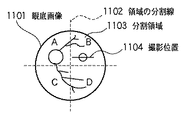
上記実施形態では、S402において、状態情報からあらかじめ定められた非抽出領域の算出ルールに則り、眼底画像領域内の非抽出領域以外の領域を基準点となる特徴の抽出領域として決定する例を示したが、これに限られない。例えば、図7の参照テーブルの別項目にあるように、あらかじめ眼底画像領域2を4分割した領域(部分領域)として認識し、眼底画像から黄斑部を抽出し、状態情報で所見のあることがわかっている黄斑部を含まない領域を抽出領域として決定してもよい。図11は、正面画像を分割した様子の一例を示す図である。図11の例では、Bを除く、A、C、Dの領域が抽出領域に該当する。
(Modification 1)
In the above embodiment, an example is shown in which, in S402, a region other than the non-extraction region in the fundus image region is determined as the feature extraction region serving as a reference point in accordance with a predetermined non-extraction region calculation rule from the state information. However, it is not limited to this. For example, as shown in another item of the reference table in FIG. 7, the fundus image area 2 is recognized as an area (partial area) obtained by dividing the fundus image area 2 into four in advance, and the macula is extracted from the fundus image, and there is a finding in the state information You may determine the area | region which does not contain the known macular part as an extraction area | region. FIG. 11 is a diagram illustrating an example of a state in which the front image is divided. In the example of FIG. 11, areas A, C, and D excluding B correspond to the extraction areas.
また、これらの抽出領域に優先ルールを設けて実施してもよい。例えば、黄斑部を含む領域Bから、黄斑部の影響を最も受けにくい位置として、経時変化の可能性の高い分割領域から、最も遠い分割領域を特徴を抽出する領域とする場合、領域Cのみを特徴の抽出領域とすることもできる。 Further, priority rules may be provided for these extraction areas. For example, in a case where a region from which a feature is extracted is selected from a divided region having a high possibility of change with time as a position that is most unlikely to be affected by the macular portion from the region B including the macular portion, only the region C is selected. It can also be a feature extraction area.
(変形例2)
また、上記実施形態では、S402において、入力された状態情報をもとに、基準とする特徴の抽出領域を決定する例を示したが、これに限られない。例えば、状態情報の入力ではなく、撮影者によりGUIを介して指定された領域に基づいてS402の基準点決定処理を実行してもよい。具体的には、撮影者によって指定された、経時変化の可能性の低い領域(特徴の抽出領域)や、または、経時変化の可能性の高い領域(特徴の非抽出領域)に基づいて基準点を決定してもよい。また、変形例1のような表示部5に表示制御して提示された分割領域の選択をユーザ(撮影者)から受け付ける受付処理を行って、選択を受け付けた部分領域に基づいて抽出領域、ひいては、基準部分を決定してもよい。さらに、選択を受け付けた部分領域を正面画像から除いた部分を基準部分として決定してもよい。このような構成とすることで、ユーザは基準部分を容易に設定することができる。
(Modification 2)
In the above-described embodiment, the example in which the reference feature extraction area is determined based on the input state information in S402 is described, but the present invention is not limited thereto. For example, the reference point determination process in S402 may be executed based on an area designated by the photographer via the GUI instead of inputting state information. Specifically, a reference point based on a region specified by the photographer that is not likely to change over time (feature extraction region) or a region that is likely to change over time (feature non-extraction region). May be determined. In addition, an acceptance process is performed in which selection of a divided area presented by display control on the
(変形例3)
また、上記実施形態の撮影処理では、S402の基準点決定処理において、入力された状態情報をもとに、基準とする特徴の抽出領域を決定する例を示したが、これに限られない。例えば、撮影者は入力をせず、断面画像の撮影位置の情報を用いて、基準の特徴の抽出領域を決定してもよい。例えば、変形例1で参照した図11の例であれば、黄斑部を抽出せずに撮影位置が経時変化の可能性の高い位置として捉え、撮影位置を含む分割領域Bを非抽出領域とし、変形例1と同様の処理で制御部1が自動的に抽出領域を決定するようにしてもよい。
(Modification 3)
In the imaging process of the above-described embodiment, an example in which the reference feature extraction region is determined based on the input state information in the reference point determination process in S402 is described, but the present invention is not limited thereto. For example, the photographer may determine the reference feature extraction region by using information on the photographing position of the cross-sectional image without input. For example, in the example of FIG. 11 referred to in the first modification, the macular portion is not extracted and the shooting position is regarded as a position that is likely to change with time, and the divided area B including the shooting position is set as a non-extraction area. The control unit 1 may automatically determine the extraction region by the same processing as that of the first modification.
(変形例4)
また、S402の基準点決定処理では、複数の状態情報による抽出領域、非抽出領域のAND、または、ORをとって生成した領域で、基準点とする特徴の抽出領域を決定してもよい。また、状態情報以外の入力部3から撮影者が任意指定した領域や制御部1により自動的に決定された領域も同様にAND、または、ORをとって生成した領域を特徴の抽出領域として決定してもよい。
(Modification 4)
In the reference point determination process in S402, the feature extraction region may be determined as a reference point in a region generated by taking AND or OR of an extraction region based on a plurality of state information and a non-extraction region. In addition, the region arbitrarily selected by the photographer from the
(変形例5)
また、上記実施形態では、S905において、S901で取得され、S904で位置合わせされた過去の眼底画像の位置情報を現在の被検眼の眼底画像上の位置情報に変換した撮影位置を撮影位置する例を示したが、これに限られない。例えば、最終的な撮影位置を決定する前に、撮影者による修正を加えられるようにしてもよい。例えば、S905の処理の終了前に、GUIの画面に表示した撮影位置を示す線分、矩形などの領域を示すグラフィックオブジェクトについて、ポインティングデバイスの操作などによってその位置や範囲の変更を可能としてもよい。
(Modification 5)
Further, in the above embodiment, in S905, the imaging position obtained by converting the positional information of the past fundus image acquired in S901 and aligned in S904 into the positional information on the fundus image of the current eye to be examined is set as the imaging position. However, the present invention is not limited to this. For example, the photographer may make corrections before determining the final shooting position. For example, before the end of the processing of S905, the position and range of a graphic object indicating an area such as a line segment or a rectangle indicating the shooting position displayed on the GUI screen may be changed by operating a pointing device or the like. .
(変形例6)
また、上記実施形態では、S905の撮影位置決定処理において、現在の被検眼の眼底画像や撮影位置を画面上に表示する例を示したが、必ずしも画面上に表示する必要はない。例えば、S905で決定された撮影位置をそのまま用いて、撮影の指示を待たず、S906の撮影処理を行ってもよい。
(Modification 6)
In the above-described embodiment, an example in which the current fundus image and the photographing position of the eye to be examined is displayed on the screen in the photographing position determination process in S905 is not necessarily displayed on the screen. For example, the shooting position determined in S905 may be used as it is, and the shooting process in S906 may be performed without waiting for a shooting instruction.
(変形例7)
また、上記実施形態では、S905の撮影位置決定処理において、現在の被検者の眼底画像上の相対的な位置情報を生成する例を示したが、これに限られない。例えば、現在の被検者の正面画像の座標系と対応づけることのできる撮影装置の座標系で示された位置情報に直接変換された撮影位置情報としてもよい。この場合、S906の撮影処理は、装置座標系の撮影位置情報を用いて撮影処理を行うことになる。
(Modification 7)
In the above-described embodiment, an example in which the relative position information on the fundus image of the current subject is generated in the imaging position determination process in S905 is described, but the present invention is not limited to this. For example, it is good also as imaging | photography position information converted directly into the positional information shown with the coordinate system of the imaging device which can be matched with the coordinate system of the front image of the present subject. In this case, the shooting process in S906 is performed using the shooting position information in the apparatus coordinate system.
(変形例8)
また、上記の実施形態では、処理対象の画像が眼の眼底画像である例について説明したが、眼底に限らず前眼部のような別の正面画像であっても同様の手法を適用することができる。また、上記の構成では、基準を点(基準点)とした場合の例を説明したが、基準線や基準領域としてもよい。また、眼底画像のような2次元画像ではなく、眼底部を撮像して再構成された眼底部のボリュームデータのような3次元領域内から基準を決定するような位置合わせを実行することも可能である。さらに、上記の実施形態においては被検眼は片方の眼の画像に着目した場合の構成例を説明したが、同じ被検者の両眼や複数の被検者の複数の眼を扱ってもよい。
(Modification 8)
In the above-described embodiment, an example in which the image to be processed is the fundus image of the eye has been described. However, the same technique may be applied to another front image such as an anterior eye segment as well as the fundus. Can do. In the above configuration, an example in which the reference is a point (reference point) has been described, but a reference line or a reference region may be used. It is also possible to perform positioning so as to determine a reference from within a three-dimensional area such as volume data of the fundus reconstructed by imaging the fundus instead of a two-dimensional image such as a fundus image It is. Further, in the above-described embodiment, the configuration example in which the eye to be examined focuses on the image of one eye has been described, but both eyes of the same subject or a plurality of eyes of a plurality of subjects may be handled. .
(その他の実施形態)
また、本発明の目的は、コンピュータプログラムやコンピュータプログラムを格納したコンピュータ読み取り可能な記録媒体によっても実現可能である。例えば、次のようにすることによっても本発明の目的は達成される。すなわち、前述した実施形態の機能を実現するソフトウェアのプログラムコードを記録した記録媒体(または記憶媒体)を、システムあるいは装置に供給する。そして、そのシステムあるいは装置のコンピュータ(またはCPUやMPU)が記録媒体に格納されたプログラムコードを読み出し実行する。この場合、記録媒体から読み出されたプログラムコード自体が前述の機能を実現することになり、そのプログラムコードを記録した記録媒体は本発明の技術的範囲に含まれる。
(Other embodiments)
The object of the present invention can also be realized by a computer program or a computer-readable recording medium storing the computer program. For example, the object of the present invention can also be achieved by the following. That is, a recording medium (or storage medium) in which a program code of software that realizes the functions of the above-described embodiments is recorded is supplied to the system or apparatus. Then, the computer (or CPU or MPU) of the system or apparatus reads and executes the program code stored in the recording medium. In this case, the program code itself read from the recording medium realizes the above-described function, and the recording medium on which the program code is recorded is included in the technical scope of the present invention.
また、コンピュータが読み出したプログラムコードを実行することにより、そのプログラムコードの指示に基づき、コンピュータ上で稼働しているオペレーティングシステム(OS)などが実際の処理の一部または全部を行う。その処理によって前述した実施形態の機能が実現される場合も本発明の技術的範囲に含まれることは言うまでもない。 Also, by executing the program code read by the computer, an operating system (OS) or the like running on the computer performs part or all of the actual processing based on the instruction of the program code. It goes without saying that the case where the functions of the above-described embodiments are realized by the processing is also included in the technical scope of the present invention.
さらに、記録媒体から読み出されたプログラムコードが、コンピュータに挿入された機能拡張カードやコンピュータに接続された機能拡張ユニットに備わるメモリに書込まれたとする。その後、そのプログラムコードの指示に基づき、その機能拡張カードや機能拡張ユニットに備わるCPUなどが実際の処理の一部または全部を行い、その処理によって前述した実施形態の各機能が実現される場合も、本発明の技術的範囲に含まれる。 Furthermore, it is assumed that the program code read from the recording medium is written in a memory provided in a function expansion card inserted into the computer or a function expansion unit connected to the computer. Thereafter, the CPU of the function expansion card or function expansion unit performs part or all of the actual processing based on the instruction of the program code, and the functions of the above-described embodiments may be realized by the processing. Are included in the technical scope of the present invention.
なお、本発明を上記記録媒体に適用する場合、その記録媒体には、先に説明したフローチャートで示される処理を実行するプログラムコードが格納されることになる。 When the present invention is applied to the recording medium, the recording medium stores program code for executing the processing shown in the flowchart described above.
以上のように、上記構成によれば、経時変化がおきるような長期間に渡った同一部位の断面画像の撮影においても、精度よく同一部位の断面画像の撮影を行うことが可能である。また、経過観察に適した比較用画像撮影の冗長な作業時間、不要な枚数の撮影画像の生成、および、撮影画像から、診断に適した画像の選別や撮影のやりなおしに要した作業時間等を縮小できることから、撮影作業の効率化につながる。 As described above, according to the above configuration, it is possible to capture a cross-sectional image of the same part with high accuracy even when capturing a cross-sectional image of the same part over a long period of time that changes with time. In addition, there are redundant work time for taking comparative images suitable for follow-up observation, generation of unnecessary number of shot images, and work time required for selecting images suitable for diagnosis and re-shooting from the taken images. Since it can be reduced, it leads to the efficiency of shooting work.
Claims (15)
前記被写体の概略画像を取得する第1取得手段と、
前記概略画像において経時変化が他の部分よりも小さい基準部分を決定する決定手段と、
詳細な撮影を行うべき前記被写体の撮影位置を第1の前記概略画像において設定する設定手段と、
前記第1の概略画像の被写体と同一の被写体について第2の前記概略画像が取得された場合、該第1の概略画像の前記基準部分と該第2の概略画像の前記基準部分とに基づいて、当該第2の概略画像を該第1の概略画像に対して位置合わせする位置合わせ手段と、
前記位置合わせされた第2の概略画像の前記第1の概略画像の前記撮影位置に対応する位置について、前記被写体の詳細な撮影画像を取得する第2取得手段と、
を備えることを特徴とする撮影装置。 A photographing device for photographing a subject that changes over time,
First acquisition means for acquiring a schematic image of the subject;
Determining means for determining a reference portion whose temporal change is smaller in the schematic image than other portions;
Setting means for setting the shooting position of the subject to be subjected to detailed shooting in the first schematic image;
When the second schematic image is acquired for the same subject as the subject of the first schematic image, based on the reference portion of the first schematic image and the reference portion of the second schematic image Positioning means for aligning the second schematic image with respect to the first schematic image;
Second acquisition means for acquiring a detailed captured image of the subject for a position corresponding to the shooting position of the first schematic image of the aligned second schematic image;
An imaging apparatus comprising:
前記状態情報を入力する入力手段と、
を更に備え、
前記決定手段は、前記入力手段に入力された状態情報に対応する前記領域を前記概略画像から除いた部分を前記基準部分として決定する
ことを特徴とする請求項1又は2に記載の撮影装置。 Reading means for reading out correspondence information indicating the correspondence between the state information indicating the state of the subject and the region where the change over time is larger than that of the other part from the storage unit;
Input means for inputting the state information;
Further comprising
3. The photographing apparatus according to claim 1, wherein the determining unit determines, as the reference portion, a portion obtained by removing the region corresponding to the state information input to the input unit from the schematic image.
前記状態情報には、病名と、疾患の進行度と、患部の名称と、診断による所見と、の少なくともいずれか1つが含まれる
ことを特徴とする請求項3に記載の撮影装置。 The subject is an affected area of a patient;
The imaging apparatus according to claim 3, wherein the state information includes at least one of a disease name, a disease progression degree, an affected area name, and a diagnosis finding.
前記部分領域の選択をユーザから受け付ける受付手段と、
を更に備え、
前記決定手段は、前記受付手段が選択を受け付けた部分領域に基づいて前記基準部分を決定することを特徴とする請求項1又は2に記載の撮影装置。 Display control means for displaying on the display means what is obtained by dividing the schematic image into a plurality of partial areas;
Accepting means for accepting selection of the partial area from a user;
Further comprising
The photographing apparatus according to claim 1, wherein the determination unit determines the reference portion based on a partial region that the reception unit has received a selection.
前記第1の概略画像と前記位置情報とを関連づけて保持する保持手段を更に備え、
前記位置合わせ手段は、前記保持手段から前記第1の概略画像を読み出して前記位置合わせを行い、
前記第2取得手段は、第2の概略画像の前記第1の概略画像の前記撮影位置に対応する位置を前記位置情報を用いて決定して、当該位置について前記詳細な撮影画像を取得する
ことを特徴とする請求項1から7のいずれか1項に記載の撮影装置。 Generating means for generating position information indicating a relative position of the photographing position set with respect to the first schematic image with respect to the reference portion;
Holding means for holding the first schematic image and the position information in association with each other;
The alignment means reads the first schematic image from the holding means and performs the alignment.
The second acquisition means determines a position corresponding to the shooting position of the first schematic image of a second schematic image using the position information, and acquires the detailed captured image for the position. The imaging device according to claim 1, wherein:
前記正面画像は、前記眼の眼底または前眼部の正面画像である
ことを特徴とする請求項9に記載の撮影装置。 The subject is an eye that is an affected area of a patient,
The imaging apparatus according to claim 9, wherein the front image is a front image of a fundus or an anterior segment of the eye.
前記第2取得手段はOCTにより前記断面画像を取得する
ことを特徴とする請求項11に記載の撮影装置。 The first acquisition means acquires the front image by a fundus camera,
The imaging apparatus according to claim 11, wherein the second acquisition unit acquires the cross-sectional image by OCT.
前記被写体の概略画像を取得する第1取得工程と、
前記概略画像において経時変化が他の部分よりも小さい基準部分を決定する決定工程と、
詳細な撮影を行うべき前記被写体の撮影位置を第1の前記概略画像において設定する設定工程と、
前記第1の概略画像の被写体と同一の被写体について第2の前記概略画像が取得された場合、該第1の概略画像の前記基準部分と該第2の概略画像の前記基準部分とに基づいて、当該第2の概略画像を該第1の概略画像に対して位置合わせする位置合わせ工程と、
前記位置合わせされた第2の概略画像の前記第1の概略画像の前記撮影位置に対応する位置について、前記被写体の詳細な撮影画像を取得する第2取得工程と、
を有することを特徴とする撮影方法。 A photographing method in a photographing device for photographing a subject that changes over time,
A first acquisition step of acquiring a schematic image of the subject;
A determination step of determining a reference portion whose temporal change is smaller than other portions in the schematic image;
A setting step of setting a shooting position of the subject to be subjected to detailed shooting in the first schematic image;
When the second schematic image is acquired for the same subject as the subject of the first schematic image, based on the reference portion of the first schematic image and the reference portion of the second schematic image An alignment step of aligning the second schematic image with respect to the first schematic image;
A second acquisition step of acquiring a detailed captured image of the subject for a position corresponding to the imaging position of the first schematic image of the aligned second schematic image;
A photographing method characterized by comprising:
Priority Applications (3)
| Application Number | Priority Date | Filing Date | Title |
|---|---|---|---|
| JP2008322956A JP2010142428A (en) | 2008-12-18 | 2008-12-18 | Photographing apparatus, photographing method, program and recording medium |
| US13/122,858 US8803964B2 (en) | 2008-12-18 | 2009-11-26 | Imaging apparatus and imaging method, program, and recording medium |
| PCT/JP2009/070263 WO2010071024A1 (en) | 2008-12-18 | 2009-11-26 | Imaging apparatus and imaging method, program, and recording medium |
Applications Claiming Priority (1)
| Application Number | Priority Date | Filing Date | Title |
|---|---|---|---|
| JP2008322956A JP2010142428A (en) | 2008-12-18 | 2008-12-18 | Photographing apparatus, photographing method, program and recording medium |
Related Child Applications (1)
| Application Number | Title | Priority Date | Filing Date |
|---|---|---|---|
| JP2015031912A Division JP5883173B2 (en) | 2015-02-20 | 2015-02-20 | Imaging apparatus, imaging method, program, and recording medium |
Publications (1)
| Publication Number | Publication Date |
|---|---|
| JP2010142428A true JP2010142428A (en) | 2010-07-01 |
Family
ID=42268697
Family Applications (1)
| Application Number | Title | Priority Date | Filing Date |
|---|---|---|---|
| JP2008322956A Ceased JP2010142428A (en) | 2008-12-18 | 2008-12-18 | Photographing apparatus, photographing method, program and recording medium |
Country Status (3)
| Country | Link |
|---|---|
| US (1) | US8803964B2 (en) |
| JP (1) | JP2010142428A (en) |
| WO (1) | WO2010071024A1 (en) |
Cited By (18)
| Publication number | Priority date | Publication date | Assignee | Title |
|---|---|---|---|---|
| JP2012030054A (en) * | 2010-07-05 | 2012-02-16 | Canon Inc | Ophthalmologic apparatus, ophthalmologic system, and storage medium |
| JP2012071113A (en) * | 2010-08-31 | 2012-04-12 | Canon Inc | Image processing apparatus, method for controlling the same, and program |
| JP2012125490A (en) * | 2010-12-17 | 2012-07-05 | Canon Inc | Ophthalmologic apparatus and control method therefor |
| JP2012161426A (en) * | 2011-02-04 | 2012-08-30 | Nidek Co Ltd | Ophthalmic photographing apparatus |
| WO2012132499A1 (en) | 2011-03-31 | 2012-10-04 | 株式会社吉田製作所 | Control device, control method and control program for optical coherence tomographic image-generating apparatuses |
| JP2012213466A (en) * | 2011-03-31 | 2012-11-08 | Canon Inc | Optical coherence tomography apparatus, method for controlling optical coherence tomography apparatus, program, and ophthalmologic system |
| JP2013075035A (en) * | 2011-09-30 | 2013-04-25 | Canon Inc | Ophthalmic apparatus, ophthalmic image processing method, and recording medium |
| JP2013135965A (en) * | 2013-04-08 | 2013-07-11 | Canon Inc | Ophthalmic apparatus |
| JP2013146445A (en) * | 2012-01-20 | 2013-08-01 | Canon Inc | Image processing apparatus and image processing method |
| JP2015195950A (en) * | 2014-04-01 | 2015-11-09 | キヤノン株式会社 | Ophthalmic apparatus and control method |
| US9204793B2 (en) | 2011-10-19 | 2015-12-08 | Canon Kabushiki Kaisha | Ophthalmologic apparatus and ophthalmologic photographing method |
| JP2016010728A (en) * | 2015-10-08 | 2016-01-21 | キヤノン株式会社 | Ophthalmic information processing system, ophthalmic information processing method, and program |
| JP2017056050A (en) * | 2015-09-17 | 2017-03-23 | キヤノン株式会社 | Ophthalmologic photographing apparatus, control method therefor, and program |
| JP2017158867A (en) * | 2016-03-10 | 2017-09-14 | キヤノン株式会社 | Ophthalmic imaging equipment |
| US9993152B2 (en) | 2012-01-20 | 2018-06-12 | Canon Kabushiki Kaisha | Image processing apparatus and image processing method |
| JP2022185838A (en) * | 2021-06-03 | 2022-12-15 | 株式会社ニデック | OCT device and imaging control program |
| WO2023100985A1 (en) * | 2021-12-03 | 2023-06-08 | 田辺三菱製薬株式会社 | Information processing system, information processing method, and program |
| JP2023096011A (en) * | 2020-05-14 | 2023-07-06 | 株式会社トプコン | Methods for Optical Coherence Tomography Angiography |
Families Citing this family (13)
| Publication number | Priority date | Publication date | Assignee | Title |
|---|---|---|---|---|
| JP4909378B2 (en) | 2009-06-02 | 2012-04-04 | キヤノン株式会社 | Image processing apparatus, control method therefor, and computer program |
| JP5436076B2 (en) | 2009-07-14 | 2014-03-05 | キヤノン株式会社 | Image processing apparatus, image processing method, and program |
| JP5917004B2 (en) | 2011-03-10 | 2016-05-11 | キヤノン株式会社 | IMAGING DEVICE AND IMAGING DEVICE CONTROL METHOD |
| DE102011015149B4 (en) * | 2011-03-25 | 2013-01-17 | Carl Zeiss Meditec Ag | Surgical microscopy system |
| JP5220155B2 (en) * | 2011-03-31 | 2013-06-26 | キヤノン株式会社 | Ophthalmic apparatus and method for controlling ophthalmic apparatus |
| JP5836634B2 (en) | 2011-05-10 | 2015-12-24 | キヤノン株式会社 | Image processing apparatus and method |
| JP5926533B2 (en) * | 2011-10-27 | 2016-05-25 | キヤノン株式会社 | Ophthalmic equipment |
| JP6188297B2 (en) * | 2012-01-25 | 2017-08-30 | キヤノン株式会社 | Image processing apparatus, image processing method, and program |
| JP5297541B2 (en) | 2012-01-26 | 2013-09-25 | キヤノン株式会社 | Ophthalmic apparatus, method for controlling ophthalmic apparatus, and program |
| EP2633804B1 (en) * | 2012-03-02 | 2017-12-06 | Nidek Co., Ltd | Ophthalmologic photographing apparatus |
| PH12013000227A1 (en) * | 2012-07-30 | 2015-03-09 | Canon Kk | Ophthalmologic apparatus and ophthalmologic method |
| JP2017072902A (en) * | 2015-10-05 | 2017-04-13 | 富士通株式会社 | Program, information processing apparatus and information processing method |
| CN108197594B (en) * | 2018-01-23 | 2020-12-11 | 北京七鑫易维信息技术有限公司 | Method and apparatus for determining pupil position |
Citations (4)
| Publication number | Priority date | Publication date | Assignee | Title |
|---|---|---|---|---|
| JPH04333972A (en) * | 1991-05-10 | 1992-11-20 | Toshiba Corp | Medical diagnosis supporting system |
| JP2001291088A (en) * | 2000-04-07 | 2001-10-19 | Ge Yokogawa Medical Systems Ltd | Medical image display device |
| JP2002140688A (en) * | 2000-11-01 | 2002-05-17 | Fuji Photo Film Co Ltd | Measurment processor for geometrically measuring image |
| JP2007252692A (en) * | 2006-03-24 | 2007-10-04 | Topcon Corp | Fundus observation device |
Family Cites Families (11)
| Publication number | Priority date | Publication date | Assignee | Title |
|---|---|---|---|---|
| JP2002219123A (en) * | 2001-01-26 | 2002-08-06 | Mitsubishi Space Software Kk | Projection transformation apparatus and method, and temporal difference image creation apparatus and method |
| US7679581B2 (en) * | 2004-08-02 | 2010-03-16 | Searete Llc | Medical overlay mirror |
| JP4034776B2 (en) * | 2004-11-12 | 2008-01-16 | 株式会社東芝 | Digital watermark detection apparatus, digital watermark detection method, and program |
| JP4916779B2 (en) | 2005-09-29 | 2012-04-18 | 株式会社トプコン | Fundus observation device |
| JP4969925B2 (en) | 2006-06-28 | 2012-07-04 | 株式会社トプコン | Fundus observation device |
| JP4822969B2 (en) * | 2006-07-27 | 2011-11-24 | 株式会社ニデック | Ophthalmic imaging equipment |
| JP4939156B2 (en) * | 2006-09-19 | 2012-05-23 | 東京エレクトロン株式会社 | Re-registration method of registration object and recording medium recording the method |
| DE602007012450D1 (en) * | 2006-10-02 | 2011-03-24 | Hansen Medical Inc | SYSTEM FOR THREE-DIMENSIONAL ULTRASOUND PICTURE |
| US8223143B2 (en) * | 2006-10-27 | 2012-07-17 | Carl Zeiss Meditec, Inc. | User interface for efficiently displaying relevant OCT imaging data |
| JP5582772B2 (en) * | 2009-12-08 | 2014-09-03 | キヤノン株式会社 | Image processing apparatus and image processing method |
| JP5025715B2 (en) * | 2009-12-08 | 2012-09-12 | キヤノン株式会社 | Tomographic imaging apparatus, image processing apparatus, image processing system, control method and program for image processing apparatus |
-
2008
- 2008-12-18 JP JP2008322956A patent/JP2010142428A/en not_active Ceased
-
2009
- 2009-11-26 US US13/122,858 patent/US8803964B2/en not_active Expired - Fee Related
- 2009-11-26 WO PCT/JP2009/070263 patent/WO2010071024A1/en not_active Ceased
Patent Citations (4)
| Publication number | Priority date | Publication date | Assignee | Title |
|---|---|---|---|---|
| JPH04333972A (en) * | 1991-05-10 | 1992-11-20 | Toshiba Corp | Medical diagnosis supporting system |
| JP2001291088A (en) * | 2000-04-07 | 2001-10-19 | Ge Yokogawa Medical Systems Ltd | Medical image display device |
| JP2002140688A (en) * | 2000-11-01 | 2002-05-17 | Fuji Photo Film Co Ltd | Measurment processor for geometrically measuring image |
| JP2007252692A (en) * | 2006-03-24 | 2007-10-04 | Topcon Corp | Fundus observation device |
Cited By (22)
| Publication number | Priority date | Publication date | Assignee | Title |
|---|---|---|---|---|
| JP2012030054A (en) * | 2010-07-05 | 2012-02-16 | Canon Inc | Ophthalmologic apparatus, ophthalmologic system, and storage medium |
| JP2012071113A (en) * | 2010-08-31 | 2012-04-12 | Canon Inc | Image processing apparatus, method for controlling the same, and program |
| JP2012125490A (en) * | 2010-12-17 | 2012-07-05 | Canon Inc | Ophthalmologic apparatus and control method therefor |
| JP2012161426A (en) * | 2011-02-04 | 2012-08-30 | Nidek Co Ltd | Ophthalmic photographing apparatus |
| US9084562B2 (en) | 2011-03-31 | 2015-07-21 | The Yoshida Dental Mfg. Co., Ltd. | Control device, control method and control program for optical coherence tomographic image-generating apparatuses |
| JP2012213466A (en) * | 2011-03-31 | 2012-11-08 | Canon Inc | Optical coherence tomography apparatus, method for controlling optical coherence tomography apparatus, program, and ophthalmologic system |
| WO2012132499A1 (en) | 2011-03-31 | 2012-10-04 | 株式会社吉田製作所 | Control device, control method and control program for optical coherence tomographic image-generating apparatuses |
| JP2013075035A (en) * | 2011-09-30 | 2013-04-25 | Canon Inc | Ophthalmic apparatus, ophthalmic image processing method, and recording medium |
| US9204793B2 (en) | 2011-10-19 | 2015-12-08 | Canon Kabushiki Kaisha | Ophthalmologic apparatus and ophthalmologic photographing method |
| JP2013146445A (en) * | 2012-01-20 | 2013-08-01 | Canon Inc | Image processing apparatus and image processing method |
| US9717409B2 (en) | 2012-01-20 | 2017-08-01 | Canon Kabushiki Kaisha | Image processing apparatus and image processing method |
| US9993152B2 (en) | 2012-01-20 | 2018-06-12 | Canon Kabushiki Kaisha | Image processing apparatus and image processing method |
| JP2013135965A (en) * | 2013-04-08 | 2013-07-11 | Canon Inc | Ophthalmic apparatus |
| JP2015195950A (en) * | 2014-04-01 | 2015-11-09 | キヤノン株式会社 | Ophthalmic apparatus and control method |
| US10524654B2 (en) | 2014-04-01 | 2020-01-07 | Canon Kabushiki Kaisha | Ophthalmologic apparatus and control method thereof, processing apparatus and processing method |
| JP2017056050A (en) * | 2015-09-17 | 2017-03-23 | キヤノン株式会社 | Ophthalmologic photographing apparatus, control method therefor, and program |
| JP2016010728A (en) * | 2015-10-08 | 2016-01-21 | キヤノン株式会社 | Ophthalmic information processing system, ophthalmic information processing method, and program |
| JP2017158867A (en) * | 2016-03-10 | 2017-09-14 | キヤノン株式会社 | Ophthalmic imaging equipment |
| JP2023096011A (en) * | 2020-05-14 | 2023-07-06 | 株式会社トプコン | Methods for Optical Coherence Tomography Angiography |
| JP2022185838A (en) * | 2021-06-03 | 2022-12-15 | 株式会社ニデック | OCT device and imaging control program |
| JP7714916B2 (en) | 2021-06-03 | 2025-07-30 | 株式会社ニデック | OCT device and imaging control program |
| WO2023100985A1 (en) * | 2021-12-03 | 2023-06-08 | 田辺三菱製薬株式会社 | Information processing system, information processing method, and program |
Also Published As
| Publication number | Publication date |
|---|---|
| WO2010071024A1 (en) | 2010-06-24 |
| US20110234785A1 (en) | 2011-09-29 |
| US8803964B2 (en) | 2014-08-12 |
Similar Documents
| Publication | Publication Date | Title |
|---|---|---|
| JP2010142428A (en) | Photographing apparatus, photographing method, program and recording medium | |
| JP5820154B2 (en) | Ophthalmic apparatus, ophthalmic system, and storage medium | |
| JP5436076B2 (en) | Image processing apparatus, image processing method, and program | |
| KR101736728B1 (en) | Information processing apparatus, information processing method and computer readable storage medium | |
| US6698885B2 (en) | Judging changes in images of the eye | |
| CN102186406A (en) | Method and apparatus for obtaining an image of an ocular feature | |
| US10165939B2 (en) | Ophthalmologic apparatus and ophthalmologic apparatus control method | |
| US9782071B2 (en) | Ophthalmologic photographing apparatus and ophthalmologic photographing method | |
| WO2014207901A9 (en) | Image processing device and image processing method | |
| JP5883173B2 (en) | Imaging apparatus, imaging method, program, and recording medium | |
| JP6289462B2 (en) | Image processing apparatus and image processing method | |
| JP2025147226A (en) | Image processing method, image processing device, and image processing program | |
| JP2018147387A (en) | System and method for processing ophthalmic examination information | |
| CN111526779B (en) | Image processing method, image processing program, image processing device, image display device, and image display method | |
| JP6825292B2 (en) | Fundus image observation program | |
| JP6723843B2 (en) | Ophthalmic equipment | |
| JP6645003B2 (en) | Ophthalmic examination information processing apparatus and ophthalmic examination information processing program | |
| JP5653055B2 (en) | Ophthalmic apparatus and control method thereof | |
| JP6957852B2 (en) | Fundus image observation program | |
| JP2018147386A (en) | System and method for processing ophthalmic examination information | |
| JP2025091832A (en) | Medical image processing device and medical image processing program | |
| JP2023158821A (en) | Information processing device, control method for information processing device, and program | |
| WO2023203992A1 (en) | Information processing device, method for controlling information processing device, and program | |
| JP2023148522A (en) | Ophthalmology image processing device, ophthalmology image processing program | |
| JP2020065695A (en) | Ophthalmologic information processing system, ophthalmologic information processing method, and program |
Legal Events
| Date | Code | Title | Description |
|---|---|---|---|
| A621 | Written request for application examination |
Free format text: JAPANESE INTERMEDIATE CODE: A621 Effective date: 20111213 |
|
| A131 | Notification of reasons for refusal |
Free format text: JAPANESE INTERMEDIATE CODE: A131 Effective date: 20121026 |
|
| A521 | Request for written amendment filed |
Free format text: JAPANESE INTERMEDIATE CODE: A523 Effective date: 20121214 |
|
| A131 | Notification of reasons for refusal |
Free format text: JAPANESE INTERMEDIATE CODE: A131 Effective date: 20130614 |
|
| A521 | Request for written amendment filed |
Free format text: JAPANESE INTERMEDIATE CODE: A523 Effective date: 20130807 |
|
| A131 | Notification of reasons for refusal |
Free format text: JAPANESE INTERMEDIATE CODE: A131 Effective date: 20140331 |
|
| A521 | Request for written amendment filed |
Free format text: JAPANESE INTERMEDIATE CODE: A523 Effective date: 20140526 |
|
| A131 | Notification of reasons for refusal |
Free format text: JAPANESE INTERMEDIATE CODE: A131 Effective date: 20141107 |
|
| A521 | Request for written amendment filed |
Free format text: JAPANESE INTERMEDIATE CODE: A523 Effective date: 20141217 |
|
| A01 | Written decision to grant a patent or to grant a registration (utility model) |
Free format text: JAPANESE INTERMEDIATE CODE: A01 Effective date: 20150123 |
|
| A045 | Written measure of dismissal of application [lapsed due to lack of payment] |
Free format text: JAPANESE INTERMEDIATE CODE: A045 Effective date: 20150525 |