JP6645003B2 - Ophthalmic examination information processing apparatus and ophthalmic examination information processing program - Google Patents
Ophthalmic examination information processing apparatus and ophthalmic examination information processing program Download PDFInfo
- Publication number
- JP6645003B2 JP6645003B2 JP2014135476A JP2014135476A JP6645003B2 JP 6645003 B2 JP6645003 B2 JP 6645003B2 JP 2014135476 A JP2014135476 A JP 2014135476A JP 2014135476 A JP2014135476 A JP 2014135476A JP 6645003 B2 JP6645003 B2 JP 6645003B2
- Authority
- JP
- Japan
- Prior art keywords
- examination
- data
- unit
- image
- ophthalmic
- Prior art date
- Legal status (The legal status is an assumption and is not a legal conclusion. Google has not performed a legal analysis and makes no representation as to the accuracy of the status listed.)
- Active
Links
- 230000010365 information processing Effects 0.000 title claims description 35
- 238000007689 inspection Methods 0.000 claims description 134
- 238000003384 imaging method Methods 0.000 claims description 85
- 238000012014 optical coherence tomography Methods 0.000 claims description 54
- 238000012360 testing method Methods 0.000 claims description 27
- 230000003287 optical effect Effects 0.000 description 130
- 238000000034 method Methods 0.000 description 29
- 238000005259 measurement Methods 0.000 description 24
- 206010025421 Macule Diseases 0.000 description 21
- 238000005286 illumination Methods 0.000 description 16
- 210000001747 pupil Anatomy 0.000 description 13
- 210000002445 nipple Anatomy 0.000 description 8
- 238000005457 optimization Methods 0.000 description 8
- 230000035945 sensitivity Effects 0.000 description 8
- 230000007246 mechanism Effects 0.000 description 7
- 238000010586 diagram Methods 0.000 description 6
- 238000001514 detection method Methods 0.000 description 5
- 210000004220 fundus oculi Anatomy 0.000 description 5
- 238000012937 correction Methods 0.000 description 4
- 230000006870 function Effects 0.000 description 4
- 239000011521 glass Substances 0.000 description 4
- 238000003780 insertion Methods 0.000 description 4
- 230000037431 insertion Effects 0.000 description 4
- 230000007774 longterm Effects 0.000 description 4
- 230000010287 polarization Effects 0.000 description 4
- 230000008569 process Effects 0.000 description 4
- 230000008859 change Effects 0.000 description 3
- 238000012790 confirmation Methods 0.000 description 3
- 210000004087 cornea Anatomy 0.000 description 3
- 238000012545 processing Methods 0.000 description 3
- 230000002207 retinal effect Effects 0.000 description 3
- 230000000007 visual effect Effects 0.000 description 3
- 206010027146 Melanoderma Diseases 0.000 description 2
- 206010064127 Solar lentigo Diseases 0.000 description 2
- 230000004913 activation Effects 0.000 description 2
- 230000004907 flux Effects 0.000 description 2
- 230000004048 modification Effects 0.000 description 2
- 238000012986 modification Methods 0.000 description 2
- 238000000926 separation method Methods 0.000 description 2
- 238000001228 spectrum Methods 0.000 description 2
- 238000004458 analytical method Methods 0.000 description 1
- 238000013459 approach Methods 0.000 description 1
- 230000005540 biological transmission Effects 0.000 description 1
- 230000004397 blinking Effects 0.000 description 1
- 230000008878 coupling Effects 0.000 description 1
- 238000010168 coupling process Methods 0.000 description 1
- 238000005859 coupling reaction Methods 0.000 description 1
- 238000003745 diagnosis Methods 0.000 description 1
- 229910052736 halogen Inorganic materials 0.000 description 1
- 150000002367 halogens Chemical class 0.000 description 1
- 238000010191 image analysis Methods 0.000 description 1
- 230000002911 mydriatic effect Effects 0.000 description 1
- 239000013307 optical fiber Substances 0.000 description 1
- 230000004044 response Effects 0.000 description 1
- 230000003595 spectral effect Effects 0.000 description 1
- 230000009466 transformation Effects 0.000 description 1
Images


Landscapes
- Eye Examination Apparatus (AREA)
Description
被検眼の検査データを扱うための眼科検査情報処理装置、及び眼科検査情報処理プログラムに関する。 The present invention relates to an ophthalmic examination information processing apparatus for handling examination data of an eye to be inspected, and an ophthalmic examination information processing program.
被検眼の検査するための眼科検査装置として、眼科用光干渉断層計(OCT:optical coherence tomography)、眼底カメラ、レーザ走査検眼鏡(SLO:scanning laser ophthalmoscope)、等の様々なモダリティ、視野計等が知られている。また、複数のモダリティを備えるコンボ機も提案され、あるモダリティによって得られた画像と、それとは別のモダリティによって得られた画像(つまり、別モダリティ画像)が同一画面上に表示される(特許文献1参照)。 Various modalities such as an ophthalmic optical coherence tomography (OCT), a fundus camera, a laser scanning ophthalmoscope (SLO), a perimeter, and the like as an ophthalmic examination apparatus for examining an eye to be examined. It has been known. In addition, a combo machine having a plurality of modalities has been proposed, and an image obtained by one modality and an image obtained by another modality (that is, another modality image) are displayed on the same screen (Japanese Patent Application Laid-Open No. H10-163873). 1).
ところで、第1のモダリティにて異なる撮影モードにて画像をそれぞれ取得する場合がある。例えば、OCTと眼底カメラの複合装置においては、OCT画像とカラー眼底画像を連続的に取得する第1モードと、OCT画像或いはカラー眼底画像を個別に取得する第2モードが設けられている場合がある。また、OCTにおいては、異なる走査位置あるいは走査パターンにてOCT画像を得る場合がよくあり、第2モードも多く用いられている。 By the way, there are cases where images are respectively acquired in different shooting modes in the first modality. For example, in a combined apparatus of an OCT and a fundus camera, a first mode for continuously acquiring an OCT image and a color fundus image and a second mode for separately acquiring an OCT image or a color fundus image may be provided. is there. In OCT, an OCT image is often obtained at different scanning positions or scanning patterns, and the second mode is often used.
しかしながら、従来装置では、第1モードを用いた場合においては、OCT画像とカラー眼底画像をセットで表示することが可能であるが、第2モードにて得られたOCT画像は、カラー眼底画像とセットで表示することは難しい。あるいは、各OCT画像とカラー眼底画像をセットで表示するには、第1モードを複数回行うという手法がありうるが、撮影を複数回行う必要があり、被検眼にとって負担である。 However, in the conventional device, when the first mode is used, the OCT image and the color fundus image can be displayed as a set, but the OCT image obtained in the second mode is the same as the color fundus image. It is difficult to display as a set. Alternatively, in order to display each OCT image and the color fundus image as a set, there may be a method of performing the first mode a plurality of times, but it is necessary to perform the imaging a plurality of times, which is a burden on the eye to be examined.
本発明は、上記問題点を鑑み、異なる眼科検査ユニットによって得られた検査データ同士を容易に確認できる眼科検査情報処理装置、及び眼科検査情報処理プログラムを提供することを技術課題とする。 The present invention has been made in consideration of the above problems, and has as its technical object to provide an ophthalmic examination information processing apparatus and an ophthalmic examination information processing program that can easily confirm examination data obtained by different ophthalmic examination units.
上記課題を解決するために、本発明は以下のような構成を備えることを特徴とする。 In order to solve the above problems, the present invention is characterized by having the following configuration.
(1) 第1の眼科検査ユニットによって得られた被検眼の第1の検査データであって、画像データである第1の検査データと、第2の眼科検査ユニットによって得られた前記被検眼の第2の検査データと、を記憶部に記憶し表示部に出力する眼科検査情報処理装置であって、
前記第1の眼科検査ユニットでの検査時に設定された撮影モードが互いに異なる複数の第1の検査データと、前記第1の検査データと同じ日にて得られた前記第2の検査データとを同一グループとして関連付けるグループ設定手段と、
前記記憶部に記憶され前記複数の第1の検査データであって前記表示部に表示された前記複数の第1の検査データのいずれかを表示部上で選択するための選択指示を受け付ける指示受付手段と、
前記指示受付手段によって選択指示された第1の検査データを前記表示部に表示すると共に、前記選択指示された第1の検査データと同一グループとして関連付けられた第2の検査データを前記記憶部から取り出し、前記第1の検査データと同時に前記表示部に表示する表示制御手段と、
を備えることを特徴とする。
(2) 眼科用光干渉断層撮影ユニットによって得られた被検眼の第1の検査データであって、画像データである第1の検査データと、眼科用光干渉断層撮影ユニットとは異なる眼科検査ユニットによって得られた前記被検眼の第2の検査データと、を記憶部に記憶し表示部に出力する眼科検査情報処理装置であって、
前記眼科用光干渉断層撮影ユニットでの検査時に設定された撮影モードが互いに異なる複数の第1の検査データと、前記第1の検査データと同じ日にて得られた前記第2の検査データとを同一グループとして関連付けるグループ設定手段と、
前記記憶部に記憶された前記複数の第1の検査データであって前記表示部に表示された前記複数の第1の検査データのいずれかを表示部上で選択するための選択指示を受け付ける指示受付手段と、
前記指示受付手段によって選択指示された第1の検査データを前記表示部に表示すると共に、前記選択指示された第1の検査データと同一グループとして関連付けられた第2の検査データを前記記憶部から取り出し、前記第1の検査データと同時に前記表示部に表示する表示制御手段と、
を備えることを特徴とする。
(3) 第1の眼科検査ユニットによって得られた被検眼の第1の検査データであって、画像データである第1の検査データと、第2の眼科検査ユニットによって得られた前記被検眼の第2の検査データと、を記憶部に記憶し表示部に出力する眼科検査情報処理装置において実行される眼科検査情報処置プログラムであって、
前記眼科検査情報処理装置のプロセッサに実行されることで、
前記第1の眼科検査ユニットでの検査時に設定された撮影モードが互いに異なる複数の第1の検査データと、前記第1の検査データと同じ日にて得られた前記第2の検査データとを同一グループとして関連付けるグループ設定ステップと、
前記記憶部に記憶された前記複数の第1の検査データであって前記表示部に表示された前記複数の第1の検査データのいずれかを表示部上で選択するための選択指示を受け付ける指示受付ステップと、
前記指示受付ステップにおいて選択指示された第1の検査データを前記表示部に表示すると共に、前記選択指示された第1の検査データと同一グループとして関連付けられた第2の検査データを前記記憶部から取り出し、前記第1の検査データと同時に前記表示部に表示する表示制御ステップと、
を前記眼科検査情報処理装置に実行させることを特徴とする。
(1) First examination data of the subject's eye obtained by the first ophthalmic examination unit, the first examination data being image data, and the first examination data of the subject's eye obtained by the second ophthalmic examination unit. An ophthalmologic examination information processing apparatus that stores second examination data in a storage unit and outputs the same to a display unit,
A plurality of first examination data having different imaging modes set at the time of examination by the first ophthalmic examination unit, and the second examination data obtained on the same day as the first examination data. Group setting means to associate as the same group;
Instruction reception for receiving a selection instruction for selecting any of the plurality of first inspection data stored in the storage unit and displayed on the display unit on the display unit Means,
The first inspection data selected and instructed by the instruction receiving means is displayed on the display unit, and the second inspection data associated as the same group with the first inspection data instructed by the selection is stored in the storage unit. Display control means for extracting and displaying the first inspection data on the display unit simultaneously with the first inspection data;
It is characterized by having.
(2) First examination data of the eye to be inspected obtained by the ophthalmic optical coherence tomography unit, the first examination data being image data, and an ophthalmic examination unit different from the ophthalmic optical coherence tomography unit An ophthalmologic examination information processing apparatus that stores the second examination data of the subject's eye obtained by the above and a storage unit and outputs the same to a display unit,
A plurality of first inspection data in which imaging modes set at the time of inspection in the ophthalmic optical coherence tomography unit are different from each other; and the second inspection data obtained on the same day as the first inspection data. Group setting means for associating
An instruction for receiving a selection instruction for selecting any of the plurality of first inspection data displayed on the display unit on the display unit, the plurality of first inspection data stored in the storage unit Reception means,
The first inspection data selected and instructed by the instruction receiving unit is displayed on the display unit, and the second inspection data associated with the selected first inspection data as the same group is stored in the storage unit. Display control means for taking out and displaying on the display unit simultaneously with the first inspection data;
It is characterized by having.
(3) First examination data of the subject's eye obtained by the first ophthalmic examination unit, the first examination data being image data, and the first examination data of the subject's eye obtained by the second ophthalmic examination unit. An ophthalmic examination information processing program executed in an ophthalmic examination information processing device that stores second examination data in a storage unit and outputs the second examination data to a display unit,
When executed by the processor of the ophthalmic examination information processing apparatus,
A plurality of first examination data having different imaging modes set at the time of examination in the first ophthalmic examination unit, and the second examination data obtained on the same day as the first examination data. A group setting step to associate as the same group,
An instruction for receiving a selection instruction for selecting any of the plurality of first inspection data displayed on the display unit on the display unit, the plurality of first inspection data stored in the storage unit Receiving step,
The first inspection data selected and instructed in the instruction receiving step is displayed on the display unit, and the second inspection data associated with the selected first inspection data as the same group is stored in the storage unit. A display control step of taking out and displaying on the display unit simultaneously with the first inspection data;
Is executed by the ophthalmic examination information processing apparatus.
<概要>
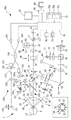
以下、本実施例の概要を図面に基づいて説明する。本実施例の眼科検査情報処理装置の説明において、被検眼のカラー眼底画像および断層画像を取得するための装置に関する例を用いる(図1参照)。なお、本実施例においては、被検眼の奥行き方向をZ方向(光軸L1方向)、奥行き方向に垂直(被検者の顔面と同一平面)な平面上の水平方向成分をX方向、鉛直方向成分をY方向として説明する。
<Overview>
Hereinafter, an outline of the present embodiment will be described with reference to the drawings. In the description of the ophthalmologic examination information processing apparatus of the present embodiment, an example relating to an apparatus for acquiring a color fundus image and a tomographic image of an eye to be examined will be used (see FIG. 1). In this embodiment, the depth direction of the subject's eye is defined as the Z direction (the direction of the optical axis L1), and the horizontal component on a plane perpendicular to the depth direction (the same plane as the face of the subject) is defined as the X direction and the vertical direction. The component is described as the Y direction.
本実施例の眼科検査情報処理装置(以下、本装置ともいう)は、例えば、第1の眼科検査ユニットによって得られた被検眼の第1の検査データと、第2の眼科検査ユニットによって得られた第2の検査データと、を記憶部72に記憶し表示部に出力する。眼科検査情報処理装置(例えば、制御部70、コンピュータ90など)は、例えば、グループ設定部(例えば、制御部70、コンピュータ90など)と、指示受付部(例えば、制御部70、コンピュータ90など)と、表示制御部(例えば、制御部70、コンピュータ90など)と、を主に備える。
The ophthalmic examination information processing apparatus according to the present embodiment (hereinafter, also referred to as the present apparatus) includes, for example, first examination data of an eye to be examined obtained by a first ophthalmic examination unit and obtained by a second ophthalmic examination unit. The stored second inspection data is stored in the
グループ設定部は、例えば、第1の眼科検査ユニットでの検査時に設定された検査モードが互いに異なる複数の第1の検査データと、第2の検査データとを同一グループとして関連付けてもよい。なお、第1の検査データは第1の画像データであってもよい。なお、第2の検査データは第2の画像データであってもよい。指示受付部は、例えば、記憶部72に記憶された複数の第1の検査データのいずれかを選択するための選択指示を受け付けてもよい。表示制御部は、例えば、指示受付部によって選択指示された第1の検査データを表示部(例えば、表示部75、表示部95など)に表示してもよい。これと共に、表示制御部は、選択指示された第1の検査データと同一グループとして関連付けられた第2の検査データを記憶部72から取り出し、第1の検査データと同時に表示部に表示してもよい。
The group setting unit may, for example, associate a plurality of pieces of first examination data having different examination modes set at the time of the examination with the first ophthalmic examination unit with the second examination data as the same group. Note that the first inspection data may be first image data. Note that the second inspection data may be second image data. The instruction receiving unit may receive, for example, a selection instruction for selecting any one of the plurality of first inspection data stored in the
本装置1において、例えば、検査モードの異なる複数の第1の検査データと、第2の検査データとが同一グループとして関連付けされるので、第1の検査データが表示される際、同一グループとして関連付けられた第2の検査データを容易に表示部に表示できる。これによって、複数の眼科検査データを用いた診断作業の効率、精度の向上が期待される。
In the
なお、グループ設定部は、同じ日にて得られた同一被検者に関する複数の第1の検査データと第2の検査データとを同一グループとして関連付けてもよい。これによって、検者は、同じ日に取得した同一被検者に関する検査データをまとめて観察しやすい。 Note that the group setting unit may associate a plurality of first test data and a plurality of second test data for the same subject obtained on the same day as the same group. This makes it easier for the examiner to collectively observe test data on the same subject acquired on the same day.
なお、グループ設定部は、互いに異なるフォルダに格納された複数の第1の検査データと、第1の検査データのいずれかと同一又は異なるフォルダに格納された第2の検査データとを同一グループとして関連づけてもよい。この場合、指示受付部によって選択指示された第1の検査データを表示部に表示すると共に、選択指示された第1の検査データと同一グループとして関連づけされた第2の検査データを記憶部72から取り出してもよい。さらに、表示制御部は、互いに異なるフォルダに格納された第1の検査データと第2の検査データとを同時に表示部に表示してもよい。
Note that the group setting unit associates the plurality of first inspection data stored in different folders with the second inspection data stored in the same or different folder as any one of the first inspection data as the same group. You may. In this case, the first inspection data selected and instructed by the instruction receiving unit is displayed on the display unit, and the second inspection data associated with the selected first inspection data as the same group is stored in the
なお、付加情報として、各検査データがどのグループに属するかを規定するグループ情報が用いられ、グループ情報が各検査データに対して設定されてもよい。この場合、グループ設定部は、グループ情報に基づいて、複数の第1の検査データと第2の検査データとを同一グループとして関連づけてもよい。グループ情報は、検査日時、撮影情報、装置本体あるいは装置の動作プログラムに関するフラグ等の付加情報に基づいて設定されてもよい。 Note that group information that defines which group each test data belongs to may be used as the additional information, and the group information may be set for each test data. In this case, the group setting unit may associate the plurality of first inspection data and the second inspection data as the same group based on the group information. The group information may be set based on additional information such as an examination date and time, photographing information, and a flag relating to an apparatus main body or an operation program of the apparatus.
なお、付加情報として検査日時、撮影情報、装置本体あるいは装置の動作プログラムに関するフラグ等が用いられ、このような付加情報が検査データに対して設定されてもよい。グループ設定部は、前述の付加情報に基づいて、設定された基準(例えば、同一の検査日か否か、撮影ソフトの一回の起動から終了まで得られた検査データか否か等)を満たすような複数の第1の検査データと第2の検査データとを同一グループとして関連づけてもよい。 As the additional information, an examination date and time, photographing information, a flag related to the apparatus main body or an operation program of the apparatus, or the like may be used, and such additional information may be set for the examination data. The group setting unit satisfies the set criteria (for example, whether the test date is the same, whether the test data is obtained from one start of the imaging software to the end thereof, etc.) based on the additional information described above. Such a plurality of first inspection data and second inspection data may be associated as the same group.
なお、グループ設定部は、付加情報として、第1の眼科検査ユニット及び第2の眼科検査ユニットの少なくともいずれかを備える眼科検査装置本体1の動作情報、眼科検査装置本体1を検者の操作に応じて動作させるためのソフトウェアに対する操作情報、電子カルテ上で予め設定された一連の検査指示情報、各検査データに関する眼底上での検査位置情報の少なくともいずれかに応じて、複数の第1の検査データと第2の検査データとを同一グループとして関連付けてもよい。なお、動作情報とは、例えば、光源の点灯に関する動作情報、または測定光の走査に関する動作情報であってもよい。なお、操作情報とは、例えば、被検者の設定動作に関する操作情報、ソフトウェアの起動・終了に関する操作情報、設定された検査日時に関する操作情報、ユーザが前回表示したデータに関する操作情報であってもよい。なお、検査指示情報とは、例えば、OCT200にて黄斑部のライン撮影とマップ撮影を行い、眼底カメラ30で標準撮影を行う等の検査指示情報であってもよい。例えば、検査指示に対応して取得された検査データは、同一のグループとして関連付けられてもよい。
In addition, the group setting unit is configured to use the operation information of the ophthalmic examination apparatus
なお、グループ設定部は、第1の眼科検査ユニット及び第2の眼科検査ユニットの両方を備える眼科検査装置1による同一被検眼への一連の検査動作を経て取得された第1の検査データ及び第2の検査データを同一グループとして関連付けてもよい。なお、一連の検査動作とは、両眼検査時において片眼に対する検査ソフトの起動・終了、被検者の選択操作、新規被検者の設定動作等であってもよい。
In addition, the group setting unit includes the first examination data and the second examination data acquired through a series of examination operations on the same subject's eye by the
なお、グループ設定部は、記憶部72への検査データの記憶を確定させる検者からの操作信号に応じて同一グループへの関連付けを行ってもよい。例えば、グループ設定部は、検査データを長期的に保存するための保存ボタンからの操作信号、検査データをデータ管理ソフトに登録させるための登録ボタンからの操作信号等に応じて同一グループへの関連付けを行ってもよい。
Note that the group setting unit may perform association with the same group in accordance with an operation signal from an examiner who determines storage of the test data in the
なお、指示受付部は、記憶部72に記憶された第2の検査データを選択するための選択指示を受け付けてもよい。この場合、表示制御部は、指示受付部によって選択指示された第2の検査データを表示部に表示すると共に、選択指示された第2の検査データと同一グループとして関連付けられた第1の検査データを選択し、第2の検査データと同時に表示部に表示してもよい。
The instruction receiving unit may receive a selection instruction for selecting the second test data stored in the
なお、表示制御部は、第1の検査データの表示と同時に、第2の検査データを自動的に表示してもよい。表示制御部は、例えば、第1の検査データが表示された状態において、表示部上のスイッチ操作に基づいて、第1の検査データと同一グループとして関連付けられた第2の検査データを表示するようにしてもよい。第2の検査データが複数ある場合、同一グループの検査データのいずれかを選択できるようにしてもよい。 The display control unit may automatically display the second inspection data at the same time as the display of the first inspection data. The display control unit displays, for example, in a state where the first inspection data is displayed, the second inspection data associated with the first inspection data as the same group based on a switch operation on the display unit. It may be. When there are a plurality of second inspection data, any of the inspection data of the same group may be selected.
なお、表示制御部は、第1の検査データに近い第2の検査データを優先的に表示部に表示してもよい。例えば、表示制御部は、検査位置(眼底上の検査部位、固視位置)が重複する或いは近接する検査データ、検査日時が近い検査データ、画像の類似度が大きい検査データ等を優先的に表示部に表示してもよい。 Note that the display control unit may preferentially display the second inspection data close to the first inspection data on the display unit. For example, the display control unit preferentially displays test data in which test positions (test sites on the fundus, fixation positions) overlap or approach, test data with close test dates and times, test data with high image similarity, and the like. It may be displayed in the section.
なお、表示制御部は、表示部に表示された第1の検査データと第2の検査データとを位置的に対応づけて表示してもよい。第1の検査データと第2の検査データとを位置的に対応づけて表示する場合、種々の表示形態がありうる。例えば、表示制御部は、第1の検査データと第2の検査データのいずれか一方において、第1の検査データと第2の検査データの他方に対応する検査位置を電子的に表示するようにしてもよい。例えば、表示制御部は、第1の検査データと第2の検査データとを画像処理によってマッチングさせることによって、これらを合成して表示するようにしてもよい。 In addition, the display control unit may display the first inspection data and the second inspection data displayed on the display unit in a position-related manner. When displaying the first inspection data and the second inspection data in a position-related manner, there are various display forms. For example, the display control unit electronically displays an inspection position corresponding to the other of the first inspection data and the second inspection data in one of the first inspection data and the second inspection data. You may. For example, the display control unit may match the first inspection data and the second inspection data by image processing, and combine and display them.
なお、表示制御部は、例えば、第1の検査データと第2の検査データに対し、位置的に共通する基準を付加して表示するようにしてもよい。例えば、各検査データ中の黄斑に対応する位置にマークを付加してもよい。 Note that the display control unit may display the first inspection data and the second inspection data, for example, by adding a common reference in position. For example, a mark may be added to a position corresponding to the macula in each test data.
例えば、第1の検査データが、眼科用光干渉断層撮影ユニット(例えば、OCT光学系200)によって取得されたOCTデータであって、第2の検査データが、眼底正面画像の場合、表示制御部は、眼底正面画像上においてOCTデータの走査位置を電子的に表示してもよい。表示制御部は、OCTデータに付加された走査位置情報に基づいて走査位置を電子的に表示してもよい。 For example, if the first inspection data is OCT data acquired by an ophthalmic optical coherence tomography unit (for example, the OCT optical system 200) and the second inspection data is a fundus front image, the display control unit May electronically display the scanning position of the OCT data on the fundus front image. The display control unit may electronically display the scanning position based on the scanning position information added to the OCT data.
なお、第1の眼科検査ユニットは、光干渉断層計(例えば、OCT光学系200)、眼底カメラ(例えば、眼底カメラ光学系30)、光走査型レーザ検眼装置(SLO)、視野計のいずれかであってもよい。この場合、第2の眼科検査ユニットは、光干渉断層計、眼底カメラ、光走査型レーザ検眼装置、視野計のいずれかであってもよく、第1の眼科検査ユニットとは異なってもよい。例えば、第1の眼科検査ユニットは、光干渉断層計であって、第2の眼科検査ユニットは、光干渉断層計とは異なってもよい。 Note that the first ophthalmic examination unit is any one of an optical coherence tomography (for example, OCT optical system 200), a fundus camera (for example, fundus camera optical system 30), an optical scanning laser optometer (SLO), and a perimeter. It may be. In this case, the second ophthalmic examination unit may be any one of an optical coherence tomograph, a fundus camera, an optical scanning laser ophthalmoscope, and a perimeter, and may be different from the first ophthalmic examination unit. For example, the first ophthalmic examination unit may be an optical coherence tomography and the second ophthalmic examination unit may be different from the optical coherence tomography.
なお、眼科用光干渉断層撮影ユニットとしては、例えば、眼底及び前眼部の少なくともいずれかの断層画像を取得可能なOCTユニット200が考えられる。眼科用光干渉断層計によって得られた被検眼の第1の検査データとしては、断層画像の他、断層画像を解析することによって得られた解析データ(例えば、層厚マップ)、血管造影画像、ドップラ―画像、偏光特性画像等が考えられる。
Note that, as the ophthalmic optical coherence tomography unit, for example, an
なお、眼科検査情報処理装置は、第1の眼科検査ユニット及び第2の眼底検ユニットの両方を備える複合型眼科検査装置(例えば、眼科検査装置1など)と接続されたシステム300(図1参照)であってもよい。この場合、複合型眼科検査装置は、例えば、モード設定部(例えば、制御部70、コンピュータ90など)を備えてもよい。モード設定部は、例えば、連続検査モードと、個別検査モードと、を設定してもよい。連続検査モードは、例えば、第1の眼科検査ユニット及び第2の眼科検査ユニットによる検査データの取得を1回のトリガ信号に基づいて連続して行う検査モードであってもよい。個別検査モードは、例えば、第1の眼科検査ユニット及び第2の眼科検査ユニットによる検査データの取得を個別のトリガ信号に基づいてそれぞれ行う個別検査モードであって、第1の眼科検査ユニットによる検査データの取得を行う第1検査モードと、第2の眼科検査ユニットによる検査データの取得を行う第2検査モードとを少なくとも有する検査モードであってもよい。グループ設定部は、連続検査モードによって得られた第2の検査データと、個別検査モードによって得られた第1の検査データとを同一グループとして関連付けてもよい。
Note that the ophthalmic examination information processing apparatus is a system 300 (see FIG. 1) connected to a combined ophthalmic examination apparatus (for example, the
なお、眼科検査情報処理装置と、第1の眼科検査ユニット及び第2の眼底検ユニットの両方を備える複合型眼科検査装置とは、別々の装置であってもよいし、一体化されていてもよい。 The ophthalmic examination information processing apparatus and the combined ophthalmic examination apparatus including both the first ophthalmic examination unit and the second fundus examination unit may be separate apparatuses or may be integrated. Good.
なお、第1の眼科検査ユニット及び第2の眼底検ユニット等を制御する制御部(例えば、制御部70)は、眼科検査情報処理装置(例えば、制御部70、コンピュータ90など)とは別に設けられてもよいし、兼用されてもよい。
Note that a control unit (for example, the control unit 70) for controlling the first ophthalmic examination unit and the second fundus examination unit and the like is provided separately from the ophthalmic examination information processing apparatus (for example, the
なお、眼科検査情報処理装置1のプロセッサ(例えば、制御部70、コンピュータ90など)は、眼科検査情報処理プログラムを実行してもよい。眼科検査情報プログラムは、例えば、設定ステップと、指示受付ステップと、表示制御ステップと、で構成されてもよい。
Note that the processor (for example, the
設定ステップは、例えば、第1の眼科検査ユニットでの検査時に設定された検査モードが互いに異なる複数の第1の検査データと、第2の検査データとを同一グループとして関連付けるステップであってもよい。指示受付ステップは、例えば、記憶部に記憶された複数の第1の検査データのいずれかを選択するための選択指示を受け付けるステップであってもよい。表示制御ステップは、例えば、指示受付ステップにおいて選択指示された第1の検査データを表示部に表示すると共に、選択指示された第1の検査データと同一グループとして関連付けられた第2の検査データを記憶部から取り出し、第1の検査データと同時に表示部に表示するステップであってもよい。 The setting step may be, for example, a step of associating a plurality of pieces of first test data having different test modes set at the time of the test with the first ophthalmic examination unit with the second test data as the same group. . The instruction receiving step may be, for example, a step of receiving a selection instruction for selecting any one of the plurality of first inspection data stored in the storage unit. In the display control step, for example, the first inspection data selected and instructed in the instruction receiving step is displayed on the display unit, and the second inspection data associated with the selected first inspection data as the same group is displayed. It may be a step of taking out from the storage unit and displaying it on the display unit simultaneously with the first inspection data.
<実施例>
図1に示すように、本実施例の眼科検査装置1の光学系は、照明光学系10、眼底カメラ光学系30、干渉光学系200(以下、OCT光学系ともいう)、固視光学系80、を主に備える。さらに、光学系は、フォーカス指標投影光学系40、アライメント指標投影光学系50、前眼部観察光学系60を備えても良い。眼底カメラ光学系30は、眼底を可視光によって撮影(例えば、無散瞳状態)することによってカラー眼底画像を得るための眼底カメラ光学系として用いられる。OCT光学系200は、被検眼眼底の断層画像を光干渉の技術を用いて非侵襲で得る。
<Example>
As shown in FIG. 1, the optical system of the
<照明光学系>
照明光学系10は、例えば、観察照明光学系と撮影照明光学系を有する。撮影照明光学系は、光源14、コンデンサレンズ15、リングスリット17、リレーレンズ18、ミラー19、黒点板20、リレーレンズ21、孔あきミラー22、対物レンズ25を主に備える。撮影光源14は、フラッシュランプ等であってもよい。黒点板20は、中心部に黒点を有する。
<Illumination optical system>
The illumination
また、観察照明光学系は、光源11、赤外フィルタ12、コンデンサレンズ13、ダイクロイックミラー16、リングスリット17から対物レンズ25までの光学系を主に備える。光源11は、ハロゲンランプ等であってもよい。赤外フィルタ12は、波長750nm以上の近赤外光を透過する。ダイクロックミラー16は、コンデンサレンズ13とリングスリット17との間に配置される。また、ダイクロイックミラー16は、光源11からの光を反射し撮影光源14からの光を透過する特性を持つ。
The observation illumination optical system mainly includes a
<眼底カメラ光学系>
眼底カメラ光学系30は、例えば、対物レンズ25、撮影絞り31、フォーカシングレンズ32、結像レンズ33、受光素子35が主に配置されている。撮影絞り31は、孔あきミラー22の開口近傍に位置する。フォーカシングレンズ32は、光軸方向に移動可能である。受光素子35は、可視域に感度を有する撮影に利用可能である。撮影絞り31は対物レンズ25に関して被検眼Eの瞳孔と略共役な位置に配置されている。フォーカシングレンズ32は、モータを備える移動機構49により光軸方向に移動される。
<Fundus camera optical system>
The retinal camera
また、結像レンズ33と受光素子35の間には、赤外光及び可視光の一部を反射し、可視光の大部分を透過する特性を有するダイクロイックミラー34が配置される。ダイクロイックミラー37の反射方向には、赤外域に感度を有する受光素子38が配置されている。ダイクロイックミラー34は、眼底カメラ光学系30の光軸と固視光学系80の光軸とを同軸にするための光路結合部材として用いられる。ダイクロイックミラー34は、例えば、眼底観察時に光路に挿入され、眼底撮影時に光路から退避される。ダイクロイックミラー34は、ハーフミラーであってよい。
Further, a
また、対物レンズ25と孔あきミラー22の間には、光路分岐部材としての挿脱可能なダイクロイックミラー(波長選択性ミラー)24が斜設されている。ダイクロイックミラー24は、OCT測定光の波長光、及びアライメント指標投影光学系50及び前眼部照明光源58の波長光(中心波長940nm)を反射する。また、ダイクロイックミラー24は、眼底観察用照明の波長光の光源波長(中心波長880nm)を含む波長900nm以下を透過する特性を有する。撮影時には、ダイクロイックミラー24は挿脱機構66により連動して跳ね上げられ、光路外に退避する。挿脱機構66は、ソレノイドとカム等により構成することができる。
A dichroic mirror (wavelength selective mirror) 24 as an optical path branching member that can be inserted and removed is provided obliquely between the
また、ダイクロイックミラー24の受光素子35側には、挿脱機構66の駆動により光路補正ガラス28が跳ね上げ可能に配置されている。光路挿入時には、光路補正ガラス28は、ダイクロイックミラー24によってシフトされた光軸L1の位置を補正する役割を持つ。
An optical
観察用の光源11を発した光束は、赤外フィルタ12により赤外光束とされ、コンデンサレンズ13、ダイクロイックミラー16により反射されてリングスリット17を照明する。そして、リングスリット17を透過した光は、リレーレンズ18、ミラー19、黒点板20、リレーレンズ21を経て孔あきミラー22に達する。孔あきミラー22で反射された光は、補正ガラス28、ダイクロイックミラー24を透過し、対物レンズ25によって被検眼Eの瞳孔付近で一旦収束した後、拡散して被検眼眼底部を照明する。
A light beam emitted from the observation
また、眼底からの反射光は、対物レンズ25、ダイクロイックミラー24、補正ガラス28、孔あきミラー22の開口部、撮影絞り31、フォーカシングレンズ32、結像レンズ33、ダイクロイックミラー37、を介して受光素子38に結像する。なお、受光素子38の出力は制御部70に入力され、制御部70は、受光素子38によって撮像される被検眼の眼底観察画像を表示部75に表示してもよい。
Light reflected from the fundus is received via the
また、撮影光源14から発した光束は、コンデンサレンズ15を介して、ダイクロイックミラー16を透過する。その後、眼底観察用の照明光と同様の光路を経て、眼底は可視光により照明される。そして、眼底からの反射光は対物レンズ25、孔あきミラー22の開口部、撮影絞り31、フォーカシングレンズ32、結像レンズ33を経て、受光素子35に結像する。
Further, a light beam emitted from the
<フォーカス指標投影光学系>
フォーカス指標投影光学系40は、赤外光源41、スリット指標板42、2つの偏角プリズム43、投影レンズ47、照明光学系10の光路に斜設されたスポットミラー44を主に備える。2つの偏角プリズム43は、スリット視標板42に取り付けられる。スポットミラー44は、照明光学系10の航路に斜設される。また、スポットミラー44はレバー45の先端に固着されている。スポットミラー44は、通常は光軸に斜設されるが、撮影前の所定のタイミングで、ロータリソレノイド46の軸の回転により、光路外に退避させられる。なお、スポットミラー44は被検眼Eの眼底と共役な位置に配置される。光源41、スリット指標板42、偏角プリズム43、投影レンズ47、スポットミラー44及びレバー45は、フォーカシングレンズ32と連動して移動機構49により光軸方向に移動される。また、フォーカス指標投影光学系40のスリット指標板42の光束は、偏角プリズム43及び投影レンズ47を介してスポットミラー44により反射された後、リレーレンズ21、孔あきミラー22、ダイクロイックミラー24、対物レンズ25を経て被検眼Eの眼底に投影される。眼底へのフォーカスが合っていないとき、不図示の指標像は、ずれ方向及びずれ量に応じて分離された状態で眼底上に投影される。一方、フォーカスが合っているときには、指標像は、合致した状態で眼底上に投影される。
<Focus index projection optical system>
The focus index projection
<アライメント指標投影光学系>
アライメント用指標光束を投影するアライメント指標投影光学系50には、図1における左上の点線内の図に示すように、撮影光軸L1を中心として同心円上に45度間隔で赤外光源が複数個配置されている。本実施例における眼科検査装置は、第1視標投影光学系(0度、及び180)と、第2視標投影光学系と、を主に備える。第1視標投影光学系は、赤外光源51とコリメーティングレンズ52を持つ。第2視標投影光学系は、第1指標投影光学系とは異なる位置に配置され、6つの赤外光源53を持つ。赤外光源51は、撮影光軸L1を通る垂直平面を挟んで左右対称に配置される。この場合、第1指標投影光学系は被検眼Eの角膜に無限遠の指標を左右方向から投影する。第2指標投影光学系は被検眼Eの角膜に有限遠の指標を上下方向もしくは斜め方向から投影する構成となっている。なお、図1の本図には、便宜上、第1指標投影光学系(0度、及び180度)と、第2指標投影光学系の一部のみ(45度、135度)が図示されている。
<Alignment index projection optical system>
The alignment target projection
<前眼部観察光学系>
被検眼の前眼部を撮像する前眼部観察(撮影)光学系60は、ダイクロイックミラー24の反射側に、ダイクロイックミラー61、絞り63、リレーレンズ64、受光素子65を主に備える。受光素子65は、赤外域の感度を持つ。また、受光素子65はアライメント指標検出用の撮像手段を兼ね、赤外光を発する前眼部照明光源58により照明された前眼部とアライメント指標が撮像される。前眼部照明光源58により照明された前眼部は、対物レンズ25、ダイクロイックミラー24及びダイクロイックミラー61からリレーレンズ64の光学系を介して受光素子65により受光される。また、アライメント指標投影光学系50が持つ光源から発せられたアライメント光束は被検眼角膜に投影される。その角膜反射像は対物レンズ25〜リレーレンズ64を介して受光素子65に受光(投影)される。
<Anterior eye observation optical system>
An anterior segment observation (photographing)
受光素子65の出力は制御部70に入力され、受光素子65によって撮像された前眼部像が表示部75に表示される。なお、前眼部観察光学系60は、被検眼に対する装置本体1のアライメント状態を検出するための検出光学系を兼用する。
The output of the
<OCT光学系>
OCT光学系200は、いわゆる眼科用光断層干渉計(OCT:Optical coherence tomography)の装置構成を持ち、眼Eの断層像を撮像する。OCT光学系200は、測定光源102から出射された光をカップラー(光分割器)104によって測定光(試料光)と参照光に分割する。OCT光学系200は、対物レンズを有する測定光学系250によって測定光を眼Eの眼底Efに導く。また、参照光を参照光学系110に導く。測定光学系250は、例えば、コリメータレンズ123、フォーカスレンズ124、走査部108、対物レンズ25などを備えてもよい。測定光は、コリメータレンズ123、フォーカスレンズ124を介し、走査部108に達し、例えば、2つのガルバノミラーの駆動によって反射方向が変えられる。そして、走査部108で反射された測定光は、リレーレンズ22を介して、ダイクロイックミラー24で反射された後、対物レンズ25を介して、被検眼眼底に集光される。その後、眼底Efによって反射された測定光と,参照光との合成による干渉光を検出器(受光素子)120に受光させる。フォーカスレンズ124は、駆動部124aの駆動によって光軸方向に移動可能である。
<OCT optical system>
The OCT
検出器120は、測定光と参照光との干渉状態を検出する。フーリエドメインOCTの場合では、干渉光のスペクトル強度が検出器120によって検出され、スペクトル強度データに対するフーリエ変換によって所定範囲における深さプロファイル(Aスキャン信号)が取得される。例えば、Spectral-domain OCT(SD−OCT)、Swept-source OCT(SS−OCT)が挙げられる。Spectral-domain OCT(SD−OCT)の場合、例えば、光源102として広帯域光源が用いられ、検出器120として分光器(スペクトロメータ)が用いられる。Swept-source OCTの場合、例えば、光源102として波長可変光源が用いられ、検出器120として単一のフォトダイオードが用いられる(平衡検出を行ってもよい)。また、Time-domain OCT(TD−OCT)であってもよい。
The
走査部108は、測定光源から発せられた光を被検眼眼底上で走査させる。例えば、走査部108は、眼底上で二次元的(XY方向(横断方向))に測定光を走査させる。走査部108は、瞳孔と略共役な位置に配置される。走査部108は、例えば、2つのガルバノミラーであり、その反射角度が駆動部151によって任意に調整される。
The
これにより、光源102から出射された光束はその反射(進行)方向が変化され、眼底上で任意の方向に走査される。これにより、眼底Ef上における撮像位置が変更される。走査部108としては、光を偏向させる構成であればよい。例えば、反射ミラー(ガルバノミラー、ポリゴンミラー、レゾナントスキャナ)の他、光の進行(偏向)方向を変化させる音響光学素子(AOM)等が用いられる。
Thus, the light beam emitted from the
参照光学系110は、眼底Efでの測定光の反射によって取得される反射光と合成される参照光を生成する。参照光学系110は、マイケルソンタイプであってもよいし、マッハツェンダタイプであっても良い。
The reference
参照光学系110は、参照光路中の光学部材を移動させることにより、測定光と参照光との光路長差を変更してもよい。例えば、参照ミラーが光軸方向に移動される。光路長差を変更するための構成は、測定光学系250の測定光路中に配置されてもよい。
The reference
より詳細には、参照光学系110は、例えば、コリメータレンズ129、参照ミラー131、参照ミラー駆動部150を主に備える。参照ミラー駆動部150は、参照光路中に配置され、参照光の光路長を変化させるべく、光軸方向に移動可能な構成になっている。光を参照ミラー131により反射することにより再度カップラー104に戻し、検出器120に導く。他の例としては、参照光学系110は、透過光学系(例えば、光ファイバー)によって形成され、カップラー104からの光を戻さず透過させることにより検出器120へと導く。
More specifically, the reference
<固視光学系>
固視光学系は、被検眼に向けて固視標を投影するために設けられている。被検者によって固視標が視認されると、視線の動きが抑制される。固視光学系80は、例えば、固視標表示体81、リレーレンズ83を備え、ダイクロイックミラー34から対物レンズ25までの眼底カメラ光学系30の光路を共用してもよい。固視標表示体81は、可視光を発する。
<Fixation optical system>
The fixation optical system is provided for projecting a fixation target toward the eye to be inspected. When the subject sees the fixation target, the movement of the line of sight is suppressed. The fixation
固視光学系80は、ダイクロイックミラー34によって、その光軸L2がOCT光学系200及び眼底カメラ光学系30の光軸L1と同軸になるように配置されている。ダイクロイックミラー34は、眼底からの反射光を透過する。
The fixation
固視標表示体81から発せられた可視光は、リレーレンズ83、ダイクロイックミラー34、結像レンズ33、フォーカシングレンズ32、孔あきミラー22、ダイクロイックミラー24、対物レンズ25を通過して被検眼眼底に集光する。被検者は可視光束を固視標として視認する。
The visible light emitted from the fixation
<操作部>
操作部74は、検者からの操作を受け付け、後述の制御部70へ操作信号を送信する。操作部74としては、各種ユーザーインターフェース(例えば、マウス、キーボード、タッチパネル、各種操作ボタン等)が用いられる。タッチパネル式のディスプレイは、表示部75として兼用されてもよい。
<Operation section>
The
<制御部>
制御部70は、装置全体の制御を司る。例えば、制御部70は、眼科検査装置1の各種制御(例えば、後述するグループ化の制御など)を司る。制御部70は、例えば、記憶部72等と接続される。記憶部72は、プログラム、画像等を記憶する。記憶部72は、例えば、ROM72a、RAM72b、不揮発性メモリ72c等を備えてもよい。ROM72aには、眼科検査装置1の動作を制御するための各種プログラム、初期値等が記憶されている。RAM72bには、各種情報が一時的に記憶される。不揮発性メモリ72cは、電源の供給が遮断されても記憶内容を保持できる非一過性の記憶媒体である。もちろん、記憶部72は、USB、フラッシュメモリ等の記憶媒体であってもよい。
<Control unit>
The
記憶部72は、例えば、第1記憶領域、第2記憶領域、第3記憶領域を備えてもよい。第1記憶領域は、例えば、画像取得手段によって取得された画像を一時的に記憶するための記憶領域である。第2記憶領域は、例えば、画像取得手段によって取得された画像を長期的に記憶するための記憶領域である。第3記憶領域は、例えば、画像取得手段によって取得された画像を複数の画像グループにグループ化するためのグループ情報が記憶されていてもよい。グループ情報とは、例えば、同一画像グループにグループ化された画像の識別番号などをグループ単位で一括りにまとめた情報である。例えば、制御部70は、画像IDを画像グループごとにまとめて記憶部72に記憶させてもよい。例えば、図2に示すように、制御部70は、振り分けられた画像の識別番号を画像グループごとに記憶部72に記憶させてもよい。
The
本実施形態の制御部70には、表示部75と、撮影開始スイッチ73、操作部74、記憶部72、コンピュータ90、各受光素子、各光源(図は略す)、各種アクチュエータ(図は略す)、固視標表示体81等が接続される。なお、撮影開始スイッチ73は、検者に操作されると、撮影開始信号を制御部70に送信する。
The
<撮影時の制御動作>
以上のような構成を備える装置において、その撮影時の制御動作について説明する。まず、検者は、例えば、黄斑撮影用の固視標を点灯させるための操作信号を操作部74への入力によって制御部70に送信する。制御部70は、指示された固視灯81を点灯させる。
<Control operation during shooting>
A control operation at the time of photographing in the apparatus having the above configuration will be described. First, the examiner transmits an operation signal for turning on a fixation target for macular imaging to the
次に、検者は、点灯した固視灯81の出射光によって形成された固視標を注視するように被検者に指示する。初期段階では、ダイクロイックミラー24は眼底カメラ光学系30の光路に挿入されており、受光素子65に撮像された前眼部画像が表示部75に表示される。
Next, the examiner instructs the subject to gaze at the fixation target formed by the emitted light of the illuminated
検者は、上下左右方向のアライメント調整として、例えば、図示無きジョイスティックを操作し、図示無き前眼部画像が表示部75に現れるように装置1の測定部を左右上下に移動させる。前眼部像が表示部75に現れるようになると、前眼部像に8つの指標像が現れるようになる。
The examiner operates a joystick (not shown) as an alignment adjustment in the up / down / left / right direction, and moves the measurement unit of the
<アライメント検出及びXYZ方向に関する自動アライメント>
8つのアライメント指標像が受光素子65に検出されると、制御部70は、自動アライメント制御を開始する。制御部70は、受光素子65から出力される撮像信号に基づいて被検眼に対する測定部のアライメント偏位量を検出する。
<Alignment detection and automatic alignment in XYZ directions>
When the eight alignment index images are detected by the
そして、制御部70は、この偏位量がアライメント完了の許容範囲に入るように、測定部を駆動制御し、自動アライメントを行う。
Then, the
また、制御部70は、前述のように検出される8つの指標からZ方向のアライメントを行う。アライメントの方法としては、例えば、特開平6−46999号に記載のアライメント方法を利用してもよい。
Further, the
また、制御部70は、Z方向についても、Z方向のアライメント基準位置に対する偏位量を求め、その偏位量が、アライメントが完了したとされるアライメント許容範囲に入るように、測定部を駆動制御し、自動アライメントを行う。
The
前述したアライメント動作によって、XYZ方向のアライメント状態がアライメント完了の条件を満たしたら、制御部70はXYZ方向のアライメントが合致したと判定し、次のステップに移行する。ここで、XYZ方向におけるアライメントが完了すると、制御部70は、アライメント完了信号を出力する。
When the alignment state in the XYZ directions satisfies the condition of completion of the alignment by the above-described alignment operation, the
<瞳孔径の判定>
アライメント完了後、制御部70は、被検眼の瞳孔状態の適否の判定を開始する。この場合、瞳孔径の適否は、受光素子65による前眼部像から検出される瞳孔エッジが、所定の瞳孔判定エリアから外れているか否かで判定される。瞳孔判定エリアの大きさは、画像中心(撮影光軸中心)を基準に、眼底照明光束が通過可能な径(例えば、直径4mm)として設定されているものである。簡易的には、画像中心を基準に左右方向及び上下方向で検出される4点の瞳孔エッジを使用する。瞳孔エッジの点が瞳孔判定エリアよりも外にあれば、撮影時の照明光量が十分に確保される(詳しくは、本出願人による特開2005−160549号公報を参考にされたい)。なお、瞳孔径の適否判定は、撮影が実行されるまで継続され、その判定結果が表示部75上に表示される。
<Determination of pupil diameter>
After the alignment is completed, the
<フォーカス状態の検出/オートフォーカス>
また、受光素子65を用いたアライメントが完了されると、制御部70は、被検眼の眼底に対するオートフォーカスを行う。表示部75または表示部95には、受光素子38で撮像された眼底画像が表示されており、眼底画像の中心にフォーカス視標投影光学系40によるフォーカス指標像が投影されている。ここで、フォーカス指標像は、フォーカスが合っていないときには分離され、フォーカスが合っているときに一致して投影される。制御部70は、指標像を画像処理により検出し、その分離情報を得る。そして、制御部70は、指標像の分離情報を基に移動機構49の駆動を制御し、眼底に対するピントが合うようにレンズ32を移動させる。
<Detection of focus state / auto focus>
When the alignment using the
<最適化制御>
アライメント完了信号が出力されると、制御部70は、最適化制御を開始するためのトリガ信号を発し、最適化の制御動作を開始する。制御部70は、最適化を行うことによって、検者が所望する眼底部位が高感度・高解像度で観察できるようにする。なお、本実施例において、最適化の制御は、光路長調整、フォーカス調整、偏光状態の調整(ポラライザ調整)、の制御である。なお、最適化の制御において、眼底に対する一定の許容条件を満たすことができればよく、最も適切な状態に調整する必要は必ずしもない。
<Optimization control>
When the alignment completion signal is output,
最適化制御において、制御部70は、初期化の制御として、参照ミラー131とフォーカシングレンズ124の位置を初期位置に設定する。初期化完了後、制御部70は、設定した初期位置から参照ミラー131を一方向に所定ステップで移動させ、第1光路長調整を行う(第1自動光路長調整)。また、第1光路長調整と並行するように、制御部70は、受光素子38から出力される受光信号によって取得される眼底画像に基づいて被検眼眼底に対する合焦位置情報を取得する。合焦位置情報が取得されると、制御部70は、フォーカスシングレンズ124を合焦位置に移動させ、オートフォーカス調整(フォーカス調整)を行う。なお、合焦位置とは、観察画像として許容できる断層画像のコントラストを取得できる位置であればよく、必ずしも、フォーカス状態の最適位置である必要はない。
In the optimization control, the
そして、フォーカス調整完了後、制御部70は、再度、参照ミラー131を光軸方向に移動させ、光路長の再調整(光路長の微調整)をする第2光路長調整を行う。第2光路長調整完了後、制御部70は、参照光の偏光状態を調節するためのポラライザ133を駆動させ、測定光の偏光状態を調整する(詳しくは、特願2012−56292号参照)。
After the focus adjustment is completed, the
以上のようにして、最適化の制御が完了されることにより、検者が所望する眼底部位が高感度・高解像度で観察できるようになる。そして、制御部70は、各撮影モードによって設定された走査方法に基づいて走査部108の駆動を制御し、眼底上で測定光を走査する。
By completing the optimization control as described above, the examiner can observe the desired fundus region with high sensitivity and high resolution. Then, the
検出器120によって検出された撮像信号(スペクトルデータ)は、コンピュータ90に送信される。コンピュータ90は、検出器120によって検出された撮像信号を受信し、撮像信号を演算処理することによって被検眼の断層画像を生成する。
The imaging signal (spectral data) detected by the
アライメント及び画質調整が完了されると、制御部70は、走査部108の駆動を制御し、眼底上で測定光を所定方向に関して走査させ、走査中に検出器120から出力される出力信号から所定の走査領域に対応する受光信号を取得して断層画像を形成する。
When the alignment and the image quality adjustment are completed, the
続いて、眼底カメラ光学系30によるカラー眼底画像の撮影について説明する。検者は、例えば、眼底カメラの標準撮影をするために、標準撮影用の固視灯を点灯させるための操作信号を操作部74への入力によって制御部70に送信する。制御部70は、操作部74からの操作信号を受け取ると、眼底カメラの標準撮影用の固視灯を点灯させる。
Next, shooting of a color fundus image by the fundus camera
次に、検者は、固視灯81の出射光によって形成された固視標を注視するように被検者に指示する。標準撮影の場合、例えば、眼底カメラ光学系30は、被検眼の黄斑と視神経乳頭の中間部分が中心に配置されるような画像を撮影できる。
Next, the examiner instructs the subject to gaze at the fixation target formed by the light emitted from the
検者は、表示部75に表示される眼底画像を観察しながら、所望する状態で撮影できるように、アライメントとフォーカスの微調整を行う。そして、検者による撮影開始スイッチ73の入力があると、撮影が実行される。制御部70は、撮影開始スイッチ73による撮影開始のトリガ信号に基づいて、挿脱機構66を駆動することによって、ダイクロイックミラー24を光路から離脱させると共に、撮影光源14を発光させる。
While observing the fundus image displayed on the
撮影光源14が発光されることによって、被検眼眼底は可視光によって照射される。眼底からの反射光は対物レンズ25、孔あきミラー22の開口部、撮影絞り31、フォーカシングレンズ32、結像レンズ33、ダイクロイックミラー37を通過し、2次元受光素子35に結像する。2次元受光素子35で撮影された眼底画像82は、制御部に受信され、その後、記憶部72に記憶される。
When the
<グループ化及び表示制御>
以下、個別撮影モード(個別検査モード)によって撮影されたモダリティの異なる画像をグループ化し、表示部75に表示するときの流れを説明する。例えば、検者は、個別撮影モードによって、黄斑ライン撮影、黄斑マップ撮影、カラー眼底画像撮影を別々に撮影する。検者は、撮影したい画像の撮影モードに切り替え、撮影を行う。検者は、撮影が終わるごとに撮影モードを切り替えることによって、黄斑ライン撮影、黄斑マップ撮影、カラー眼底画像撮影等の撮影を順に行う。
<Grouping and display control>
Hereinafter, the flow of grouping images having different modalities photographed in the individual photographing mode (individual inspection mode) and displaying the images on the
なお、黄斑ライン撮影モードとは、OCT光学系200を用いて、眼底黄斑部において直線状に測定光を走査させる撮影モードである。黄斑マップ撮影とは、OCT光学系200を用いて、眼底黄斑部において測定光を二次元的に走査させる撮影モード(好ましくは、ラスタースキャン)である。カラー眼底画像撮影とは、眼底カメラ光学系30を用いて、カラー眼底正面画像を撮影する撮影モードである。
Note that the macular line imaging mode is an imaging mode in which the OCT
[黄斑ライン撮影]
図3のステップ1において、制御部70は、黄斑ライン撮影を開始する。まず、検者は操作部74の操作によって黄斑ライン撮影モードを選択する(図4参照)。操作部74は、検者からの操作に基づいて制御部70に操作信号を送信する。制御部70は、操作部74からの操作信号を受け付け、撮影モードを黄斑ライン撮影モードに設定する。
[Macular line photography]
In
制御部70は、例えば、検者によって撮影開始スイッチ73から出力された撮影開始信号(レリーズ信号)を受け付け、黄斑ライン撮影を開始する。例えば、制御部70は、走査部30の駆動を制御し、黄斑部に対してラインスキャンを行う。制御部70は、図5(a)に示すような黄斑ライン画像(黄斑部の断層画像)を取得する。取得動作が完了されると、制御部70は、表示画面を撮影操作画面から画像確認画面に移行させ、黄斑ライン画像を表示部75に表示させる。これによって、検者は、黄斑ライン画像が良好に撮影されたかどうか確認することができる。
The
ここで、検者による操作部74からの操作信号に基づいて、黄斑ライン画像がOKである旨が受け付けられると、制御部70は、例えば、取得された黄斑ライン画像に対してタグ情報(付加情報)を設定し、記憶部72に一時的に記憶させる。タグ情報とは、例えば、画像の識別番号、被検者名、撮影日時、左眼・右眼、撮影部位、走査パターン、固視位置等の撮影画像に関連する情報である。制御部70は、黄斑ライン画像を一時的に記憶させると、撮影操作画面に移行し、ステップ2に進む。
Here, when it is received that the macular line image is OK based on the operation signal from the
[黄斑マップ撮影]
ステップ2において、制御部70は、黄斑マップ撮影を行う。まず、検者は、操作部74の操作によって黄斑マップ撮影モードを選択する。操作部74は、検者からの操作に基づいて制御部70に操作信号を送信する。制御部70は、操作部74からの操作信号を受け付け、撮影モードを黄斑マップ撮影モードに切り替える。
[Macula map shooting]
In step 2, the
撮影モードが黄斑マップ撮影モードに切り替えられ、調整作業が完了されると、検者は、再度撮影開始スイッチ73を押す。制御部70は、撮影開始スイッチ73から出力された撮影開始信号を受け付けると、黄斑マップ撮影を開始する。例えば、制御部70は走査部の駆動を制御し、黄斑部に対してラスタースキャンを行う。制御部70は、図5(b)に示すような黄斑マップ画像(黄斑部に関する3次元OCTデータ)を取得する。3次元OCTデータは、例えば、ラスタースキャンを形成するスキャンライン毎の断層画像からなる。
When the photographing mode is switched to the macular map photographing mode and the adjustment work is completed, the examiner presses the photographing start switch 73 again. When receiving the shooting start signal output from the shooting start switch 73, the
制御部70は、表示画面を撮影操作画面から画像確認画面に移行させ、黄斑マップ画像を表示部75に表示させる(例えば、3次元OCTデータに基づいて形成されるOCT正面画像が表示される)。これによって、検者は、黄斑マップ画像が良好に撮影されたかどうか確認することができる。
The
続いて、検者による操作部74からの操作信号に基づいて、黄斑マップ画像がOKである旨が受け付けられると、制御部70は、取得された黄斑マップ画像にタグ情報を設定し、記憶部72に一時的に記憶させる。ここで、付加されるタグ情報は、前述の黄斑ライン画像に対して設定されたタグ情報とは、異なる情報となる。制御部70は、黄斑マップ画像を一時的に記憶させると、撮影操作画面に移行し、ステップ3に進む。
Subsequently, when it is received that the macular map image is OK based on the operation signal from the
[カラー眼底撮影]
ステップ3において、制御部70は、黄斑中心のカラー眼底撮影を行う。まず、検者は、操作部74の操作によってカラー眼底撮影モードを選択する。操作部74は、検者からの操作に基づいて制御部70に操作信号を送信する。制御部70は、操作部74からの操作信号を受け付け、撮影モードをカラー眼底撮影モードに切り替える。
[Color fundus photography]
In
撮影モードがカラー眼底撮影モードに切り替わると、検者は、再度撮影開始スイッチ73を押す。制御部70は、撮影開始スイッチ73から出力された撮影開始信号を受け付けると、カラー眼底撮影を開始する。例えば、制御部70は、撮影光源14を発光させ、2次元受光素子35によって被検眼のカラー眼底正面画像を取得する。制御部70は、図5(c)に示すような黄斑中心のカラー眼底正面画像を取得する。
When the imaging mode is switched to the color fundus imaging mode, the examiner presses the imaging start switch 73 again. When receiving the imaging start signal output from the imaging start switch 73, the
制御部70は、表示画面を撮影操作画面から画像確認画面に移行させ、カラー眼底正面画像を表示部75に表示させる。これによって、検者は、カラー眼底正面画像が良好に撮影されたかどうか確認することができる。
The
続いて、検者による操作部74からの操作信号に基づいて、カラー眼底正面画像がOKである旨が受け付けられると、制御部70は、取得された黄斑中心のカラー眼底正面画像にタグ情報を設定し、記憶部72に記憶させる。ここで、付加されるタグ情報は、前述の黄斑ライン画像及び黄斑マップ画像に対して設定されたタグ情報とは、異なる情報となる。制御部70は、カラー眼底正面画像を一時的に記憶させる。上記のようにして撮影作業が終了され、操作部74からの操作信号に基づいて、画像解析画面に移行する旨、或いは撮影ソフトを終了する旨が受け付けられると、制御部70は、ステップ4に進む。
Subsequently, when it is received that the color fundus front image is OK based on the operation signal from the
[画像の記憶]
ステップ4において、制御部70は、各撮影モードで撮影された画像を長期的に記憶部72に記憶させる。
[Image storage]
In step 4, the
一例としては、記憶部72に一時的に記憶された黄斑ライン画像、黄斑マップ画像、カラー眼底正面画像をまとめて記憶部72に長期的に記憶させる。制御部70は、画像を長期的に記憶部72に記憶させると、ステップ5に進む。
As an example, the macular line image, the macular map image, and the color fundus front image temporarily stored in the
[画像のグループ化]
ステップ5において、例えば、制御部70は、取得された黄斑ライン画像、黄斑マップ画像、及びカラー眼底正面画像をグループ化し、同一の画像グループとして関連づける。制御部70は、関連付けされたグループとして識別するためのグループ情報を記憶部72に記憶させる。ここで、グループ情報は、各検査データがどのグループに属するかを規定する。
[Grouping Images]
In step 5, for example, the
より詳細には、例えば、図6に示すように、撮影された画像の患者名、撮影日、撮影パターン等の情報とともに、グループの番号が記憶される。図6の例では、○○日に患者Aに関して、黄斑ライン撮影、黄斑マップ撮影、カラー眼底撮影を行っている。そして、△△日とは異なる△△日に患者Aに関して、黄斑マップ撮影、カラー眼底撮影を行い、患者Bに関して、乳頭マップ撮影、カラー眼底撮影を行っている。この場合、記憶部72のデータベース上では、○○日に撮影された患者Aに関する黄斑ライン画像、黄斑マップ画像、カラー眼底画像に対して第1のグループ番号が設定され、第1の画像グループにグループ化される。そして、△△日に撮影された患者Aに関する黄斑マップ画像、カラー眼底画像に対して第2のグループ番号が設定され、第2の画像グループにグループ化される。さらに、△△日に撮影された患者Bに関する乳頭マップ画像と、カラー眼底画像に対して第3のグループ番号が設定され、第3の画像グループにグループ化される。図6のように、撮影日、患者という順に優先的にグループ化されてもよい。さらに、図6に示すように、1つの画像データは複数の画像グループ(例えば、第1〜第5の画像グループなど)にグループ化されてもよい。
More specifically, for example, as shown in FIG. 6, a group number is stored together with information such as a patient name, a photographing date, and a photographing pattern of a photographed image. In the example of FIG. 6, macular line imaging, macular map imaging, and color fundus imaging are performed on patient A on day XX. On day △△ different from day △△, patient A performs macular map photography and color fundus photography, and patient B performs nipple map photography and color fundus photography. In this case, on the database of the
なお、グループ化の方法として、例えば、前述のように長期的に記憶部72に記憶されたタイミングが同じ画像を同一の画像グループとして登録する方法であってもよい。例えば、ステップ4において同じタイミングでまとめて記憶された黄斑ライン画像、黄斑マップ画像、カラー眼底正面画像のそれぞれの識別番号を抽出し、グループ情報として記憶部72に記憶させてもよい。したがって、例えば、「2014年4月30日13時20分15秒」に記憶された画像は、第1の画像グループとしてグループ化され、「2014年4月30日13時22分50秒」に記憶された画像は、第1の画像グループとは別の第2画像グループとしてグループ化される。
Note that, as a grouping method, for example, a method of registering images having the same timing stored in the
上記のような方法によって、制御部70は異なるモダリティによって取得された画像のグループ化を行う。なお、制御部70は、上記の方法を個別に用いてもよいし、組み合わせた方法を用いてもよい。このように制御部70は、画像をグループ化するグループ設定手段として機能する。制御部70は、グループ情報を記憶部72に記憶させると、ステップ6に進む。なお、グループ化の方法については、種々の方法があるので、変容例にて説明する。
In the above-described manner, the
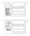
[表示]
ステップ6において、制御部70は、例えば、画像選択画面を表示部75に表示させる。例えば、図7に示すように、制御部70は、ある被検者に関する画像の一覧画面を表示部75に表示させる。一覧画面には、例えば、様々なモダリティによって取得された画像がフォルダ毎に一覧表示される。制御部70は、画像選択画面を表示部75に表示させると、ステップ7に進む。各フォルダには、1回の撮影モードにて得られた少なくとも一つの撮影画像が格納されており、表示部75には、各フォルダに格納された少なくとも一部の画像がサムネイル画像として表示部75上に表示される。なお、フォルダ毎にサムネイル画像が表示されるレイアウトではなく、フォルダに分類されていない状態で各撮影画像が一覧表示されるレイアウトであってもよい。
[display]
In step 6, the
ステップ7において、制御部70は、様々なモダリティによって得られた画像(フォルダ)の中から、あるモダリティの画像を選択するための選択指示を受け付ける。一例としては、一覧画面に表示された眼底断層画像および眼底正面画像のいずれかが検者によって選択され、タッチされる。このとき、制御部70は、操作部74として用いられるタッチパネルの検出信号に基づいて、検者からの選択指示を受け付ける。このように、制御部70は、第1画像の選択指示を受け付ける指示受付手段として機能する。制御部70は、選択指示を受け付けるとステップ8に進む。なお、制御部70は、マウスのクリック操作によって検者からの選択指示を受け付けてもよい。
In step 7, the
ステップ8において、制御部70は、前述のように選択された画像(第1の画像)と同一グループとして関連付けられた画像を検索する。例えば、制御部70は、ステップ7の選択指示によって選択された第1の画像グループに属する画像データを検索する。この場合、例えば、制御部70は、記憶部72に記憶されたグループ情報の中から、第1の画像グループとして設定された画像を検索する。制御部70は、第1の画像グループを検索するとステップ9に進む。
In step 8, the
ステップ9において、制御部70は、第1の画像グループにおいて、選択された画像とは別のモダリティによって取得された画像が存在するか判定する。制御部70は、第1画像とは別のモダリティによって取得された画像が存在しないと判定した場合はステップ10に進み、存在すると判定した場合は、ステップ11に進む。
In
ステップ10において、制御部70は、選択指示された画像を表示部75に拡大して表示させる。より詳細には、選択されたフォルダに格納された撮影画像を、表示部75に拡大して表示させる。制御部70は、第1画像を表示部75に表示させると、画像の表示制御を終了する。
In
ステップ11において、制御部70は、第1の画像グループの中で、選択された画像とは別のモダリティによって取得された複数の画像のいずれかを選出する。別のモダリティによって取得された複数の画像のいずれか(以下、第2の画像)は、選択指示された画像とともに表示部75に表示される。より詳細には、第1の画像とは別のフォルダに格納され、かつ、別のモダリティによって取得された複数の画像のいずれかを選出する。なお、制御部70は、第1の画像とともに表示部75に表示させることに適した画像を第2の画像として選出してもよい。
In
同一の画像グループとして関連付けられた複数の画像から第2画像を選出する方法として、例えば、眼底上の撮影部位に基づいて画像を選出する方法が考えられる。例えば、制御部70は、第1の画像のタグ情報から撮影部位情報を取得し、同じ画像グループ内の撮影部位がより近い画像を第2画像として選出してもよい。
As a method of selecting a second image from a plurality of images associated as the same image group, for example, a method of selecting an image based on an imaging region on the fundus can be considered. For example, the
一例として、第1の画像が黄斑ライン撮影によって取得された断層画像である場合を説明する。仮に、第1の画像と同一の画像グループにおいて、黄斑中心が撮影部位として設定されたカラー眼底正面画像と、乳頭中心が撮影部位として設定されたカラー眼底正面画像とが存在したとき、制御部70は、撮影部位が重複する黄斑中心のカラー眼底画像を第2の画像として選出してもよい。
As an example, a case where the first image is a tomographic image obtained by macular line imaging will be described. In the same image group as the first image, when there is a color fundus front image in which the macula center is set as the imaging region and a color fundus front image in which the nipple center is set as the imaging region, the
なお、別のモダリティによって取得された画像が一つしかない場合、制御部70は、この一つの画像を第2の画像として選出してもよい。
When there is only one image acquired by another modality, the
以上のように、制御部70は、画像グループ内の複数の画像の中から一つの第2画像を選出するデータ選出手段として機能する。制御部70は、第2画像を選出すると、ステップ12に進む。
As described above, the
ステップ12において、制御部70は、ステップ11で選出した第2画像を記憶部72から取り出し、第1の画像と同時に表示部75に表示させる(図8参照)。制御部70は、第1画像と第2画像を表示部75に表示させると、表示制制御を終了する。
In
以上のように、取得された画像が自動的にグループ化されることによって、検者は、画像ごとに別の画像との関連付けを設定する手間が省ける。さらに、画像グループが定まっているため、関連データの表示が容易である。例えば、別のモダリティによって得られた画像が関連付けられるため、検者は、複数の検査データを容易に確認でき、診断を行い易い。 As described above, the acquired images are automatically grouped, so that the examiner does not have to set the association with another image for each image. Further, since the image group is determined, the display of the related data is easy. For example, since images obtained by different modalities are associated with each other, the examiner can easily confirm a plurality of pieces of examination data and can easily make a diagnosis.
より詳細には、撮影モードが異なる複数の第1の画像データと、第2の画像データとが同一グループとして関連付けされるので、第1の画像データが表示部75に表示される際、同一グループとして関連付けられた第2の画像データが容易に表示部75に表示される。
More specifically, since the plurality of first image data having different shooting modes and the second image data are associated as the same group, when the first image data is displayed on the
なお、画像グループの中から第2の画像として適した画像が自動で選出されることによって、検者は、グループ内の画像から適した画像を選ぶ手間が省ける。 In addition, by automatically selecting an image suitable as the second image from the image group, the examiner can save the trouble of selecting an appropriate image from the images in the group.
<変容例>
なお、グループ化の方法としては、以下のように種々の変容がありうる。上記の方法を個別に用いてもよいし、組み合わせた方法を用いてもよい。
<Transformation example>
Note that the grouping method may have various modifications as described below. The above methods may be used individually or in combination.
例えば、複数の撮影モードでの撮影が予め設定されたコンボ撮影モードが設定されてから解除されるまでの間に、撮影された画像を同一の画像グループとして登録する方法が考えられる。コンボ撮影モードとしては、例えば、黄斑ライン撮影モード、黄斑ライン撮影モード、カラー眼底撮影モードを順に行うことが予め設定されたモードが考えられる。 For example, a method is conceivable in which the captured images are registered as the same image group between the time when the preset combo shooting mode is set and the time when the shooting in the plurality of shooting modes is canceled until the shooting is canceled. As the combo shooting mode, for example, a mode in which a macular line shooting mode, a macula line shooting mode, and a color fundus shooting mode are sequentially set may be considered.
この場合、コンボ撮影モードとして予め設定された各撮影モードでの撮影が完了した場合、制御部70は、コンボ撮影モードにおいて撮影された各画像を、同一の画像グループとしてグループ化してもよい。より詳細には、第1のコンボ撮影モードが設定された場合、得られた各画像は、第1の画像グループに登録され、次の第2のコンボ撮影モードが設定された場合、得られた各画像は、第2の画像グループに登録される。
In this case, when shooting in each shooting mode preset as the combo shooting mode is completed, the
他の例としては、眼科検査装置1を用いて撮影を行うための撮影ソフトウェアが起動されてから終了されるまでに撮影された画像が同一の画像グループとしてグループ化されてもよい。したがって、撮影ソフトの起動・終了ごとに別の画像グループとしてグループ化が行われる。
As another example, images captured from when the imaging software for performing imaging using the
また、グループ化の方法として、例えば、撮影条件の近い画像を同一の画像グループとして登録する方法が考えられる。例えば、制御部70は、画像を取得した撮影日時、右眼左眼、撮影パターン、固視位置情報などを画像のタグ情報から参照し、画像のグループ化を行ってもよい。より詳細には、制御部70は、画像の撮影日時が同じ、または近い画像を同一の画像グループとしてグループ化してもよい。さらに、制御部70は、例えば、右眼の画像グループと、左眼の画像グループとに分けてグループ化してもよい。さらに、制御部70は、例えば、黄斑ライン撮影、黄斑マップ撮影、乳頭サークル撮影、乳頭ラジアル等の断層画像の撮影モード毎に分けてグループ化してもよい。さらに、制御部70は、例えば、黄斑中心撮影、乳頭中心撮影、黄斑と乳頭の中間点撮影、パノラマ撮影等の眼底正面画像の固視灯の点灯位置によってグループ化してもよい。
As a grouping method, for example, a method of registering images having similar shooting conditions as the same image group can be considered. For example, the
この場合、例えば、撮影日が異なる画像は、別の画像グループとしてグループ化される。さらに、右眼左眼、撮影パターン、固視位置情報等の異なる画像は、別の画像グループとしてグループ化されてもよい。 In this case, for example, images having different shooting dates are grouped as different image groups. Further, different images such as right eye left eye, photographing pattern, fixation position information, and the like may be grouped as another image group.
また、グループ化の方法として、例えば、予め指定されたモダリティによって取得された画像を同一グループとして登録する方法が考えられる。例えば、被検者の検査項目が予め決まっている場合、制御部70は、予定された検査に関係するモダリティの画像を同一グループに設定してもよい。一例としては、制御部70は、電子カルテ等から被検者が受ける検査項目を取得し、それらの検査に用いられるモダリティの画像を同一の画像グループとしてグループ化してもよい。この場合、例えば、検査項目に関係しないモダリティによって取得された画像は、別の画像グループとしてグループ化される。なお、制御部70は、検査項目を取得する検査項目取得手段として機能する。
As a method of grouping, for example, a method of registering images acquired by a modality specified in advance as the same group can be considered. For example, when the examination items of the subject are predetermined, the
また、グループ化の方法として、例えば、連続撮影モード(連続検査モード)によって連続して撮影された画像を同一の画像グループとして登録する方法が考えられる。例えば、連続撮影モードは、黄斑ライン撮影、黄斑マップ撮影、カラー眼底撮影等の撮影を連続して行う撮影モードである。例えば、図4に例示する画面において、検者は、連続して撮影したい項目を選択する。撮影項目が選択されると、制御部70は、選択された項目について連続で撮影を行う。制御部70は、連続撮影モードによって取得された黄斑ライン画像、黄斑マップ画像、黄斑中心のカラー眼底正面画像をグループ化してもよい。この場合、連続撮影モードが終了した時点で画像がグループ化され、次に撮影された画像は別の画像グループとしてグループされてもよい。
Further, as a grouping method, for example, a method of registering images consecutively photographed in the continuous photographing mode (continuous inspection mode) as the same image group can be considered. For example, the continuous photographing mode is a photographing mode in which photographing such as macular line photographing, macular map photographing, and color fundus photographing is continuously performed. For example, on the screen illustrated in FIG. 4, the examiner selects items to be continuously photographed. When a shooting item is selected, the
なお、以上の説明において、黄斑ライン撮影、黄斑マップ撮影、カラー眼底撮影の順で撮影する場合を説明したが、撮影の順番は、入れ替わってもよい。なお、一般的にカラー眼底撮影は、フラッシュの発光が被検者の負担となるため、最後に撮影する場合が多い。また、撮影パターンも前述のものに限らない。眼底断層像撮影の場合は、黄斑クロス撮影、黄斑ラジアル撮影、乳頭マップ撮影、乳頭ラジアル撮影、乳頭サークル撮影等の撮影モードで撮影されてもよい。 Note that, in the above description, the case of imaging in the order of macular line imaging, macular map imaging, and color fundus imaging has been described, but the order of imaging may be switched. In general, in the color fundus imaging, the emission of the flash is a burden on the subject, and therefore the imaging is often performed last. Further, the photographing pattern is not limited to the one described above. In the case of fundus tomographic imaging, imaging may be performed in an imaging mode such as macular cross imaging, macular radial imaging, nipple map imaging, nipple radial imaging, or nipple circle imaging.
なお、以上の説明において、制御部70は、画像を長期的に保存するタイミングによってグループ化できるとしたが、これに限らない。例えば、制御部70は、記憶部72に記憶された画像を画像管理ソフトに登録するタイミングに基づいて画像をグループ化してもよい。
In the above description, the
なお、制御部70によって自動的にグループ化されグループ情報は、後で修正できてもよい。例えば、グループ修正画面等で、検者によってグループ情報を修正できるようにしてもよい。例えば、画像をあとからグループに追加したい場合、グループ情報を編集することによって、画像を追加することができる。また、グループ情報を編集して新たに画像グループを作成してもよい。
Note that the group information may be automatically grouped by the
なお、本実施例において、グループ情報が、各画像に対して付加されることによって管理される。これによって、各画像をグループごとに同じ場所(例えば、同一のフォルダ)に記憶させる必要がなく、画像を別の場所(例えば、別のフォルダ)に分けて記憶させることができる。したがって、画像を記憶する記憶部(例えば、ハードディスクドライブ)の容量が削減される。 In this embodiment, the group information is managed by being added to each image. Thus, it is not necessary to store each image in the same location (for example, the same folder) for each group, and images can be stored separately in different locations (for example, different folders). Therefore, the capacity of a storage unit (for example, a hard disk drive) for storing images is reduced.
<第2の画像の選択>
なお、複数の画像から第2の画像を選出する方法の変容例を以下に示す。例えば、撮影時の固視灯の点灯位置に基づいて画像を選出する方法が考えられる。例えば、制御部70は、第1の画像のタグ情報から固視灯の位置情報を取得し、同じ画像グループ内の固視灯位置の近い画像を第2の画像として選出してもよい。
<Selection of second image>
In addition, a modified example of a method of selecting a second image from a plurality of images will be described below. For example, a method of selecting an image based on a lighting position of a fixation lamp at the time of photographing can be considered. For example, the
また、複数の画像から第2の画像を選出する方法として、例えば、第1の画像に対する位置ずれ量に基づいて画像を選出する方法が考えられる。例えば、制御部70は、第1の画像と画像グループ内の画像とのずれ量を算出し、ずれ量の小さい画像を第2画像として選出してもよい。なお、ずれ量は、例えば、第1の画像とのマッチング処理によって算出されてもよい。
Further, as a method of selecting a second image from a plurality of images, for example, a method of selecting an image based on a positional shift amount with respect to the first image is considered. For example, the
さらに、制御部70は、第1の画像に対する画像の類似度に基づいて、第2の画像を選出してもよい。例えば、第1の画像に対して、同一の画像グループ内での異なるモダリティによって得られた画像との類似度を解析し、類似度の大きい画像を第2画像として選出してもよい。これによって、例えば、被検者の瞬き等によって上手く撮影されなかった画像は選出されなくなる。なお、類似度は、例えば画像の一部をマッチングした際の、重複領域の画素数、輝度分布の相関性、相互相関係数等に基づいて求めてもよい。このような制御は、断層画像と同時に取得される赤外正面画像と、カラー正面画像と同時に取得される赤外正面画像とを用いて、断層画像とカラー正面画像とを関連付けるような場合に有利である。
Further, the
なお、以上の説明において、制御部70は、同一画像グループの中から、第2の画像として適したものを第1の画像とともに表示させることとしたが、これに限らない。例えば、制御部70は、図9(a)に示すように、第1の画像を表示する際に、第1画像と同一の画像グループに属する画像の一覧を表示できてもよい。例えば、検者は、一覧の中から第1の画像とともに表示させる画像を選択できてもよい。制御部70は、画像グループの中から選択された第2の画像を第1の画像とともに表示してもよい。このように、制御部70は、第2の画像を選択的に表示できてもよい。
In the above description, the
なお、以上の説明において、制御部70は、選択された第1の画像と同一画像グループに属する画像の中から適した第2の画像を選出し、第1の画像とともに表示部75に表示させるものとしたが、必ずしも適した画像を選出しなくともよい。同一画像グループに属する画像であればどの画像を選出してもよい。
In the above description, the
なお、制御部70は、眼底断層画像、眼底正面画像とは別の検査情報を取得し、グループ化してもよい。例えば、制御部70は、被検者の前眼部正面画像、前眼部断層画像等をグループ化してもよい。加えて、制御部70は、眼底断層画像を解析することで取得された被検眼の網膜の厚さ情報をグループ化してもよい。その他、制御部70は、図示無き視野計で測定された被検眼の視野感度情報等をグループ化してもよい。つまり、扱われるデータは、眼の検査に関する検査データであればよい。
Note that the
そして、制御部70は、選択された検査データ(例えば、眼底断層画像、眼底正面画像)と同一のグループとして関連付けられた第1のグループから、前眼部正面画像、前眼部断層画像、厚さ情報、視野感度情報の少なくともいずれかを第2画像として選出し、表示部75に表示させてもよい。例えば、図9(b)に示すように、制御部70は、網膜の厚さ情報や、被検眼の視野感度情報を眼底正面画像等に重畳表示させてもよい。
Then, the
なお、眼科検査装置1は、眼科用光干渉断層計(OCT:optical coherence tomography)、眼底カメラの他に、レーザ走査検眼鏡(SLO:scanning laser ophthalmoscope)、等の様々なモダリティが一体的に設けられてもよい。また、制御部70は、外部装置のモダリティによって取得された被検眼のデータを取得してもよい。
The
1 眼科検査装置
34 ダイクロックミラー
70 制御部
72 記憶部
75 表示部
80 固視光学系
90 コンピュータ
95 表示部
104 カップラー
110 参照光学系
200 OCT光学系
Claims (8)
前記第1の眼科検査ユニットでの検査時に設定された撮影モードが互いに異なる複数の第1の検査データと、前記第1の検査データと同じ日にて得られた前記第2の検査データとを同一グループとして関連付けるグループ設定手段と、
前記記憶部に記憶され前記複数の第1の検査データであって前記表示部に表示された前記複数の第1の検査データのいずれかを表示部上で選択するための選択指示を受け付ける指示受付手段と、
前記指示受付手段によって選択指示された第1の検査データを前記表示部に表示すると共に、前記選択指示された第1の検査データと同一グループとして関連付けられた第2の検査データを前記記憶部から取り出し、前記第1の検査データと同時に前記表示部に表示する表示制御手段と、
を備えることを特徴とする眼科検査情報処理装置。 First examination data of an eye to be examined obtained by a first ophthalmic examination unit, the first examination data being image data, and a second examination data of the eye to be examined acquired by a second ophthalmic examination unit. An ophthalmic examination information processing apparatus that stores test data and a storage unit and outputs the same to a display unit,
A plurality of first examination data having different imaging modes set at the time of examination by the first ophthalmic examination unit, and the second examination data obtained on the same day as the first examination data. Group setting means to associate as the same group,
Instruction reception for receiving a selection instruction for selecting any of the plurality of first inspection data stored in the storage unit and displayed on the display unit on the display unit Means,
The first inspection data selected and instructed by the instruction receiving unit is displayed on the display unit, and the second inspection data associated with the selected first inspection data as the same group is stored in the storage unit. Display control means for extracting and displaying the first inspection data on the display unit simultaneously with the first inspection data;
An ophthalmologic examination information processing apparatus, comprising:
前記指示受付手段によって選択指示された第1の検査データを前記表示部に表示すると共に、前記選択指示された第1の検査データと同一グループとして関連づけされた前記第2の検査データを前記記憶部から取り出すことによって、互いに異なるフォルダに格納された前記第1の検査データと前記第2の検査データとを同時に前記表示部に表示可能であることを特徴とする請求項1の眼科検査情報処理装置。 The group setting means sets the plurality of first inspection data stored in different folders and the second inspection data stored in the same or different folder as any one of the first inspection data as the same group Association,
The first inspection data selected and instructed by the instruction receiving unit is displayed on the display unit, and the second inspection data associated with the selected first inspection data as a same group is stored in the storage unit. 2. The ophthalmologic examination information processing apparatus according to claim 1, wherein the first examination data and the second examination data stored in different folders can be simultaneously displayed on the display unit by taking out the first examination data and the second examination data. .
前記表示制御手段は、前記指示受付手段によって選択指示された第2の検査データを表示部に表示すると共に、前記選択指示された第2の検査データと同一グループとして関連付けられた第1の検査データを選択し、前記第2の検査データと同時に前記表示部に表示することを特徴とする請求項1または2の眼科検査情報処理装置。 The instruction receiving means receives a selection instruction for selecting the second inspection data stored in the storage unit,
The display control means displays the second inspection data selected and instructed by the instruction receiving means on a display unit, and the first inspection data associated with the second inspection data selected and instructed as the same group. 3. The ophthalmic examination information processing apparatus according to claim 1, wherein the information is selected and displayed on the display unit simultaneously with the second examination data.
前記眼科用光干渉断層撮影ユニットでの検査時に設定された撮影モードが互いに異なる複数の第1の検査データと、前記第1の検査データと同じ日にて得られた前記第2の検査データとを同一グループとして関連付けるグループ設定手段と、
前記記憶部に記憶された前記複数の第1の検査データであって前記表示部に表示された前記複数の第1の検査データのいずれかを表示部上で選択するための選択指示を受け付ける指示受付手段と、
前記指示受付手段によって選択指示された第1の検査データを前記表示部に表示すると共に、前記選択指示された第1の検査データと同一グループとして関連付けられた第2の検査データを前記記憶部から取り出し、前記第1の検査データと同時に前記表示部に表示する表示制御手段と、
を備えることを特徴とする眼科検査情報処理装置。 First examination data of the subject's eye obtained by the ophthalmic optical coherence tomography unit, the first examination data being image data, and an ophthalmic examination unit different from the ophthalmic optical coherence tomography unit. An ophthalmologic examination information processing apparatus that stores the second examination data of the subject's eye in a storage unit and outputs it to a display unit,
A plurality of first inspection data having different imaging modes set at the time of inspection in the ophthalmic optical coherence tomography unit; and the second inspection data obtained on the same day as the first inspection data. Group setting means for associating as a same group,
An instruction for receiving a selection instruction for selecting any of the plurality of first inspection data displayed on the display unit on the display unit, the plurality of first inspection data stored in the storage unit Reception means,
The first inspection data selected and instructed by the instruction receiving unit is displayed on the display unit, and the second inspection data associated with the selected first inspection data as the same group is stored in the storage unit. Display control means for extracting and displaying the first inspection data on the display unit simultaneously with the first inspection data;
An ophthalmologic examination information processing apparatus, comprising:
第1の眼科検査ユニット及び前記第2の眼科検査ユニットの両方を備える複合型眼科検査装置と接続されたシステムであって、
前記複合型眼科検査装置は、
前記第1の眼科検査ユニット及び前記第2の眼科検査ユニットによる検査データの取得を1回のトリガ信号に基づいて連続して行う連続検査モードと、
前記第1の眼科検査ユニット及び前記第2の眼科検査ユニットによる検査データの取得を個別のトリガ信号に基づいてそれぞれ行う個別検査モードであって、前記第1の眼科検査ユニットによる検査データの取得を行う第1検査モードと、前記第2の眼科検査ユニットによる検査データの取得を行う第2検査モードとを少なくとも有する個別検査モードと、
を設定可能なモード設定手段を備え、
前記グループ設定手段は、
前記連続検査モードによって得られた第2の検査データと、前記個別検査モードによって得られた第1の検査データとを同一グループとして関連付けることを特徴とする眼科検査情報処理装置。 The ophthalmologic examination information processing apparatus according to any one of claims 1 to 6,
A system connected to a combined ophthalmic examination apparatus including both a first ophthalmic examination unit and the second ophthalmic examination unit,
The combined ophthalmic examination apparatus,
A continuous examination mode in which acquisition of examination data by the first ophthalmic examination unit and the second ophthalmic examination unit is continuously performed based on one trigger signal;
An individual examination mode in which acquisition of examination data by the first ophthalmic examination unit and the second ophthalmic examination unit is performed based on an individual trigger signal, wherein acquisition of examination data by the first ophthalmic examination unit is performed. A first examination mode to be performed, and an individual examination mode having at least a second examination mode for acquiring examination data by the second ophthalmic examination unit;
Mode setting means that can set
The group setting means,
An ophthalmologic examination information processing apparatus, wherein the second examination data obtained in the continuous examination mode and the first examination data obtained in the individual examination mode are associated as the same group.
前記眼科検査情報処理装置のプロセッサに実行されることで、
前記第1の眼科検査ユニットでの検査時に設定された撮影モードが互いに異なる複数の第1の検査データと、前記第1の検査データと同じ日にて得られた前記第2の検査データとを同一グループとして関連付けるグループ設定ステップと、
前記記憶部に記憶された前記複数の第1の検査データであって前記表示部に表示された前記複数の第1の検査データのいずれかを表示部上で選択するための選択指示を受け付ける指示受付ステップと、
前記指示受付ステップにおいて選択指示された第1の検査データを前記表示部に表示すると共に、前記選択指示された第1の検査データと同一グループとして関連付けられた第2の検査データを前記記憶部から取り出し、前記第1の検査データと同時に前記表示部に表示する表示制御ステップと、
を前記眼科検査情報処理装置に実行させることを特徴とする眼科検査情報処置プログラム。 First examination data of an eye to be examined obtained by a first ophthalmic examination unit, the first examination data being image data, and a second examination data of the eye to be examined acquired by a second ophthalmic examination unit. Examination data, an ophthalmic examination information processing program executed in the ophthalmic examination information processing device that stores in the storage unit and outputs to the display unit,
When executed by the processor of the ophthalmic examination information processing apparatus,
A plurality of first examination data having different imaging modes set at the time of examination by the first ophthalmic examination unit, and the second examination data obtained on the same day as the first examination data. A group setting step to associate as the same group,
An instruction for receiving a selection instruction for selecting any of the plurality of first inspection data displayed on the display unit on the display unit, the plurality of first inspection data stored in the storage unit Receiving step,
The first inspection data selected and instructed in the instruction receiving step is displayed on the display unit, and the second inspection data associated with the selected first inspection data as a same group is stored in the storage unit. A display control step of taking out and displaying on the display unit simultaneously with the first inspection data;
An ophthalmic examination information processing program causing the ophthalmic examination information processing apparatus to execute the above.
Priority Applications (1)
| Application Number | Priority Date | Filing Date | Title |
|---|---|---|---|
| JP2014135476A JP6645003B2 (en) | 2014-06-30 | 2014-06-30 | Ophthalmic examination information processing apparatus and ophthalmic examination information processing program |
Applications Claiming Priority (1)
| Application Number | Priority Date | Filing Date | Title |
|---|---|---|---|
| JP2014135476A JP6645003B2 (en) | 2014-06-30 | 2014-06-30 | Ophthalmic examination information processing apparatus and ophthalmic examination information processing program |
Publications (3)
| Publication Number | Publication Date |
|---|---|
| JP2016013210A JP2016013210A (en) | 2016-01-28 |
| JP2016013210A5 JP2016013210A5 (en) | 2017-07-27 |
| JP6645003B2 true JP6645003B2 (en) | 2020-02-12 |
Family
ID=55229957
Family Applications (1)
| Application Number | Title | Priority Date | Filing Date |
|---|---|---|---|
| JP2014135476A Active JP6645003B2 (en) | 2014-06-30 | 2014-06-30 | Ophthalmic examination information processing apparatus and ophthalmic examination information processing program |
Country Status (1)
| Country | Link |
|---|---|
| JP (1) | JP6645003B2 (en) |
Families Citing this family (3)
| Publication number | Priority date | Publication date | Assignee | Title |
|---|---|---|---|---|
| JP6922350B2 (en) * | 2017-03-31 | 2021-08-18 | 株式会社ニデック | Imaging device and imaging control program |
| JP6935725B2 (en) * | 2017-10-31 | 2021-09-15 | 株式会社ニデック | Ophthalmologic imaging equipment |
| JP7135346B2 (en) | 2018-03-06 | 2022-09-13 | 株式会社ニデック | OCT data processor and OCT data processing program |
Family Cites Families (13)
| Publication number | Priority date | Publication date | Assignee | Title |
|---|---|---|---|---|
| JPS61170434A (en) * | 1985-01-25 | 1986-08-01 | キヤノン株式会社 | Opthalmic measuring apparatus |
| JP2000300517A (en) * | 1999-04-19 | 2000-10-31 | Topcon Corp | Ophthalmologic diagnostic support device and recording medium therefor |
| JP2002032245A (en) * | 2000-07-17 | 2002-01-31 | Nidek Co Ltd | Medical image processing method and medical image processing system |
| JP4233439B2 (en) * | 2003-11-28 | 2009-03-04 | 株式会社ニデック | Ophthalmic equipment |
| EP2233065B8 (en) * | 2009-03-23 | 2015-11-25 | Nidek Co., Ltd. | Ophthalmic observation apparatus |
| JP5242472B2 (en) * | 2009-03-23 | 2013-07-24 | 株式会社ニデック | Ophthalmic observation device |
| EP2347701B1 (en) * | 2010-01-21 | 2017-01-04 | Nidek Co., Ltd | Ophthalmic photographing apparatus |
| JP5545630B2 (en) * | 2010-01-21 | 2014-07-09 | 株式会社ニデック | Ophthalmic imaging equipment |
| JP5767014B2 (en) * | 2011-05-07 | 2015-08-19 | 株式会社ニデック | Ophthalmic observation system and image processing method |
| CN103491851B (en) * | 2011-05-30 | 2016-04-27 | 奥林巴斯株式会社 | Medical information recording device |
| EP4201304A1 (en) * | 2012-10-24 | 2023-06-28 | Nidek Co., Ltd. | Ophthalmic analysis apparatus |
| JP6229255B2 (en) * | 2012-10-24 | 2017-11-15 | 株式会社ニデック | Ophthalmic analysis apparatus and ophthalmic analysis program |
| JP6236761B2 (en) * | 2012-10-24 | 2017-11-29 | 株式会社ニデック | Ophthalmic analysis apparatus and ophthalmic analysis program |
-
2014
- 2014-06-30 JP JP2014135476A patent/JP6645003B2/en active Active
Also Published As
| Publication number | Publication date |
|---|---|
| JP2016013210A (en) | 2016-01-28 |
Similar Documents
| Publication | Publication Date | Title |
|---|---|---|
| JP6354979B2 (en) | Fundus photographing device | |
| JP4819478B2 (en) | Ophthalmic imaging equipment | |
| JP6566541B2 (en) | Ophthalmic equipment | |
| JP6213708B2 (en) | Ophthalmic photographing apparatus and ophthalmic photographing program | |
| JP2007252693A (en) | Eyeground observation apparatus | |
| JP6498398B2 (en) | Ophthalmic equipment | |
| JP6349878B2 (en) | Ophthalmic photographing apparatus, ophthalmic photographing method, and ophthalmic photographing program | |
| JP4949504B2 (en) | Ophthalmic imaging equipment | |
| US9848767B2 (en) | Ophthalmological apparatus | |
| JP6407631B2 (en) | Ophthalmic equipment | |
| JP6645003B2 (en) | Ophthalmic examination information processing apparatus and ophthalmic examination information processing program | |
| JP5807371B2 (en) | Ophthalmic imaging equipment | |
| JP6421919B2 (en) | Ophthalmic imaging equipment | |
| JP6108845B2 (en) | Ophthalmic observation device | |
| JP5319010B2 (en) | Ophthalmic imaging equipment | |
| JP5255711B2 (en) | Ophthalmic imaging equipment | |
| JP2016049368A (en) | Ophthalmological photographing apparatus | |
| JP6507536B2 (en) | Ophthalmic imaging apparatus and ophthalmologic imaging program | |
| JP6311045B2 (en) | Ophthalmic observation device | |
| JP6464565B2 (en) | Fundus photographing device | |
| JP5306554B2 (en) | Ophthalmic imaging equipment | |
| JP5319009B2 (en) | Fundus image display apparatus and ophthalmologic photographing apparatus including the same. | |
| WO2023203992A1 (en) | Information processing device, method for controlling information processing device, and program | |
| JP6349879B2 (en) | Fundus photographing device | |
| JP2023158821A (en) | Information processing unit, control method of information processing unit, and program |
Legal Events
| Date | Code | Title | Description |
|---|---|---|---|
| A521 | Request for written amendment filed |
Free format text: JAPANESE INTERMEDIATE CODE: A523 Effective date: 20170615 |
|
| A621 | Written request for application examination |
Free format text: JAPANESE INTERMEDIATE CODE: A621 Effective date: 20170615 |
|
| A977 | Report on retrieval |
Free format text: JAPANESE INTERMEDIATE CODE: A971007 Effective date: 20180405 |
|
| A131 | Notification of reasons for refusal |
Free format text: JAPANESE INTERMEDIATE CODE: A131 Effective date: 20180517 |
|
| A601 | Written request for extension of time |
Free format text: JAPANESE INTERMEDIATE CODE: A601 Effective date: 20180717 |
|
| A521 | Request for written amendment filed |
Free format text: JAPANESE INTERMEDIATE CODE: A523 Effective date: 20180918 |
|
| A131 | Notification of reasons for refusal |
Free format text: JAPANESE INTERMEDIATE CODE: A131 Effective date: 20190305 |
|
| A601 | Written request for extension of time |
Free format text: JAPANESE INTERMEDIATE CODE: A601 Effective date: 20190425 |
|
| A521 | Request for written amendment filed |
Free format text: JAPANESE INTERMEDIATE CODE: A523 Effective date: 20190704 |
|
| TRDD | Decision of grant or rejection written | ||
| A01 | Written decision to grant a patent or to grant a registration (utility model) |
Free format text: JAPANESE INTERMEDIATE CODE: A01 Effective date: 20191210 |
|
| A61 | First payment of annual fees (during grant procedure) |
Free format text: JAPANESE INTERMEDIATE CODE: A61 Effective date: 20191223 |
|
| R150 | Certificate of patent or registration of utility model |
Ref document number: 6645003 Country of ref document: JP Free format text: JAPANESE INTERMEDIATE CODE: R150 |
|
| R250 | Receipt of annual fees |
Free format text: JAPANESE INTERMEDIATE CODE: R250 |
|
| R250 | Receipt of annual fees |
Free format text: JAPANESE INTERMEDIATE CODE: R250 |