JP2010096374A - Absorption heat pump - Google Patents

Absorption heat pump Download PDF

Info

Publication number
JP2010096374A
JP2010096374A JP2008265863A JP2008265863A JP2010096374A JP 2010096374 A JP2010096374 A JP 2010096374A JP 2008265863 A JP2008265863 A JP 2008265863A JP 2008265863 A JP2008265863 A JP 2008265863A JP 2010096374 A JP2010096374 A JP 2010096374A
Authority
JP
Japan
Prior art keywords
solution
concentrated solution
pipe
regenerator
pump
Prior art date
Legal status (The legal status is an assumption and is not a legal conclusion. Google has not performed a legal analysis and makes no representation as to the accuracy of the status listed.)
Granted
Application number
JP2008265863A
Other languages
Japanese (ja)
Other versions
JP5501597B2 (en
Inventor
Osayuki Inoue
修行 井上
Current Assignee (The listed assignees may be inaccurate. Google has not performed a legal analysis and makes no representation or warranty as to the accuracy of the list.)
Ebara Refrigeration Equipment and Systems Co Ltd
Original Assignee
Ebara Refrigeration Equipment and Systems Co Ltd
Priority date (The priority date is an assumption and is not a legal conclusion. Google has not performed a legal analysis and makes no representation as to the accuracy of the date listed.)
Filing date
Publication date
Application filed by Ebara Refrigeration Equipment and Systems Co Ltd filed Critical Ebara Refrigeration Equipment and Systems Co Ltd
Priority to JP2008265863A priority Critical patent/JP5501597B2/en
Publication of JP2010096374A publication Critical patent/JP2010096374A/en
Application granted granted Critical
Publication of JP5501597B2 publication Critical patent/JP5501597B2/en
Active legal-status Critical Current
Anticipated expiration legal-status Critical

Links

Images

Classifications

    • YGENERAL TAGGING OF NEW TECHNOLOGICAL DEVELOPMENTS; GENERAL TAGGING OF CROSS-SECTIONAL TECHNOLOGIES SPANNING OVER SEVERAL SECTIONS OF THE IPC; TECHNICAL SUBJECTS COVERED BY FORMER USPC CROSS-REFERENCE ART COLLECTIONS [XRACs] AND DIGESTS
    • Y02TECHNOLOGIES OR APPLICATIONS FOR MITIGATION OR ADAPTATION AGAINST CLIMATE CHANGE
    • Y02ATECHNOLOGIES FOR ADAPTATION TO CLIMATE CHANGE
    • Y02A30/00Adapting or protecting infrastructure or their operation
    • Y02A30/27Relating to heating, ventilation or air conditioning [HVAC] technologies
    • YGENERAL TAGGING OF NEW TECHNOLOGICAL DEVELOPMENTS; GENERAL TAGGING OF CROSS-SECTIONAL TECHNOLOGIES SPANNING OVER SEVERAL SECTIONS OF THE IPC; TECHNICAL SUBJECTS COVERED BY FORMER USPC CROSS-REFERENCE ART COLLECTIONS [XRACs] AND DIGESTS
    • Y02TECHNOLOGIES OR APPLICATIONS FOR MITIGATION OR ADAPTATION AGAINST CLIMATE CHANGE
    • Y02BCLIMATE CHANGE MITIGATION TECHNOLOGIES RELATED TO BUILDINGS, e.g. HOUSING, HOUSE APPLIANCES OR RELATED END-USER APPLICATIONS
    • Y02B30/00Energy efficient heating, ventilation or air conditioning [HVAC]
    • Y02B30/62Absorption based systems

Abstract

<P>PROBLEM TO BE SOLVED: To provide an absorption heat pump capable of stably avoiding crystallization of absorption solution even when a solution pump cannot be operated before dilution operation of the absorption solution is completed. <P>SOLUTION: The absorption heat pump 1 includes: an absorber 10; a regenerator 30; a diluted solution line 16; a concentrated solution line 35 having the solution pump 35p pressure feeding concentrated solution Sa; and a dilution pipe 58A (58B) having a backflow prevention means 59A (59B) allowing a flow of diluted solution Sw from the diluted solution line 16 side to the concentrated solution line 35 side and blocking a flow of the concentrated solution Sa pressure fed by the solution pump 35p from the concentrated solution line 35 side to the diluted solution line 16 side. Even when the solution pump 35p cannot be operated, the diluted solution Sw can be mixed with the concentrated solution Sa via the dilution pipe 58A (58B) so as to dilute the concentrated solution Sa. <P>COPYRIGHT: (C)2010,JPO&INPIT

Description

本発明は吸収ヒートポンプに関し、特に吸収ヒートポンプの吸収溶液の結晶防止に関する。   The present invention relates to an absorption heat pump, and more particularly to prevention of crystallization of an absorption solution of an absorption heat pump.

低温の熱源から熱を汲み上げて高温の熱源にする機器であるヒートポンプのうち、熱駆動のものとして、吸収ヒートポンプが知られている。吸収ヒートポンプは、吸収溶液が冷媒の蒸気を吸収する際に発生する吸収熱で被加熱媒体を加熱して熱を汲み上げる。吸収ヒートポンプは、吸収溶液に対して冷媒の吸収及び蒸発を適宜行わせることにより、吸収溶液の濃度及び露点温度を適宜変化させて吸収ヒートポンプサイクルを継続させている。   Among heat pumps that are devices that pump heat from a low-temperature heat source into a high-temperature heat source, an absorption heat pump is known as a heat pump. The absorption heat pump heats the medium to be heated with the absorption heat generated when the absorption solution absorbs the vapor of the refrigerant, and pumps up the heat. The absorption heat pump causes the absorption solution to appropriately absorb and evaporate the refrigerant, thereby changing the concentration of the absorption solution and the dew point temperature as appropriate to continue the absorption heat pump cycle.

吸収ヒートポンプサイクルにおいて、吸収ヒートポンプの運転中は温度が高い吸収溶液の濃度が高い部分は、そのままの濃度で温度が低下すると結晶してしまい、吸収溶液が流れなくなってしまう。このような不都合を回避するため、一般に、吸収ヒートポンプの運転を停止する際は、吸収溶液を循環させる溶液ポンプの運転を継続させて、吸収溶液の濃度が高い部分を希釈する希釈運転が行われる。吸収溶液の希釈が必要なのは、通常の停止工程における場合のみならず、停電や溶液ポンプが故障した場合でも同様である。停電の発生等があった場合でも吸収溶液を希釈する技術として、非通電時に解放する電磁弁が取り付けられた管で蒸発器の冷媒液貯留部と再生器から吸収器へ吸収溶液を搬送する管又は再生器とを接続し、溶液ポンプを運転することができなくなった場合に蒸発器の冷媒液を再生器に流入させて吸収溶液を希釈するものがある(例えば、特許文献1参照。)。
特開昭58−31262号公報(第2頁左下欄、図1等)
In the absorption heat pump cycle, during the operation of the absorption heat pump, the portion where the concentration of the absorption solution having a high temperature is crystallized when the temperature is lowered at the same concentration, and the absorption solution does not flow. In order to avoid such inconvenience, generally, when the operation of the absorption heat pump is stopped, the operation of the solution pump for circulating the absorption solution is continued, and a dilution operation for diluting a portion having a high concentration of the absorption solution is performed. . The absorption solution needs to be diluted not only in the normal shutdown process but also in the case of a power failure or failure of the solution pump. As a technology to dilute the absorbing solution even if a power failure occurs, a tube that carries the absorbing solution from the refrigerant liquid storage part of the evaporator and the regenerator to the absorber with a tube attached with a solenoid valve that is released when not energized Alternatively, there is one that dilutes the absorbing solution by connecting the regenerator and allowing the refrigerant liquid of the evaporator to flow into the regenerator when the solution pump cannot be operated (see, for example, Patent Document 1).
JP 58-31262 A (2nd page, lower left column, FIG. 1 etc.)

しかしながら、蒸発器の冷媒液を再生器に流入させる場合は、再生器から吸収器へ吸収溶液を搬送する管に高濃度の吸収溶液が残ってしまう。また、蒸発器の冷媒液を再生器から吸収器へ吸収溶液を搬送する管内に流入させる場合も、蒸発器内の冷媒液の量が再生器から吸収器へ吸収溶液を搬送する管内に保有される吸収溶液の量に比べて少ないので、再生器から吸収器へ吸収溶液を搬送する管内の吸収溶液を十分に希釈することができない場合があった。   However, when the refrigerant liquid of the evaporator is caused to flow into the regenerator, the high-concentration absorbing solution remains in the pipe that conveys the absorbing solution from the regenerator to the absorber. In addition, when the refrigerant liquid of the evaporator is caused to flow into the pipe that transports the absorbing solution from the regenerator to the absorber, the amount of the refrigerant liquid in the evaporator is held in the pipe that transports the absorbing solution from the regenerator to the absorber. In some cases, the absorbent solution in the tube that transports the absorbent solution from the regenerator to the absorber cannot be sufficiently diluted.

本発明は上述の課題に鑑み、吸収溶液の希釈運転が完了する前に溶液ポンプを運転することができなくなった場合でも吸収溶液が結晶することを安定的に回避することができる吸収ヒートポンプを提供することを目的とする。   In view of the above-described problems, the present invention provides an absorption heat pump that can stably avoid crystallization of an absorption solution even when the solution pump cannot be operated before the dilution operation of the absorption solution is completed. The purpose is to do.

上記目的を達成するために、本発明の第1の態様に係る吸収ヒートポンプは、例えば図1に示すように、吸収溶液Saが冷媒蒸気Veを吸収して濃度が低下した希溶液Swとなる際に発生する吸収熱で被加熱媒体Wqを加熱する吸収器10と;希溶液Swを導入し加熱して、希溶液Swから冷媒Vgを蒸発させて濃度が上昇した濃溶液Saを生成する再生器30と;希溶液Swを吸収器10から再生器30に導く希溶液ライン16と;濃溶液Saを再生器30から吸収器10に導く濃溶液ライン35であって、濃溶液Saを圧送する溶液ポンプ35pを有する濃溶液ライン35と;希溶液ライン16内の希溶液Swを濃溶液ライン35内に導く希釈管58A(58B)であって、希溶液ライン16側から濃溶液ライン35側への希溶液Swの流れを許し、濃溶液ライン35側から希溶液ライン16側への溶液ポンプ35pで圧送された濃溶液Saの流れを遮断する逆流防止手段59A(59B)を有する希釈管58A(58B)とを備える。   In order to achieve the above object, the absorption heat pump according to the first aspect of the present invention, for example, as shown in FIG. 1, the absorption solution Sa absorbs the refrigerant vapor Ve and becomes a diluted solution Sw having a reduced concentration. An absorber 10 that heats the medium Wq to be heated with absorption heat generated in the regenerator; a regenerator that generates a concentrated solution Sa having an increased concentration by introducing and heating the diluted solution Sw to evaporate the refrigerant Vg from the diluted solution Sw 30; a dilute solution line 16 for introducing the dilute solution Sw from the absorber 10 to the regenerator 30; and a concentrated solution line 35 for introducing the concentrated solution Sa from the regenerator 30 to the absorber 10, and a solution for pumping the concentrated solution Sa A concentrated solution line 35 having a pump 35p; a dilution pipe 58A (58B) for introducing the diluted solution Sw in the diluted solution line 16 into the concentrated solution line 35, from the diluted solution line 16 side to the concentrated solution line 35 side Of dilute solution Sw And a dilution pipe 58A (58B) having backflow prevention means 59A (59B) for blocking the flow of the concentrated solution Sa pumped by the solution pump 35p from the concentrated solution line 35 side to the diluted solution line 16 side. .

このように構成すると、希溶液ライン内の希溶液を濃溶液ライン内に導く希釈管であって、希溶液ライン側から濃溶液ライン側への希溶液の流れを許し、濃溶液ライン側から希溶液ライン側への溶液ポンプで圧送された濃溶液の流れを遮断する逆流防止手段を有する希釈管を備えるので、吸収溶液の希釈運転が完了する前に溶液ポンプを運転することができなくなった場合でも希溶液を濃溶液に混合させることができて濃溶液を希釈することができ、濃溶液が結晶することを安定的に回避することができる。   With this configuration, the dilution pipe guides the dilute solution in the dilute solution line into the concentrated solution line, allowing the dilute solution to flow from the dilute solution line side to the concentrated solution line side, and diluting from the concentrated solution line side. When equipped with a dilution tube with backflow prevention means that blocks the flow of concentrated solution pumped by the solution pump to the solution line side, the solution pump cannot be operated before the absorption solution dilution operation is completed However, the dilute solution can be mixed with the concentrated solution, the concentrated solution can be diluted, and the concentrated solution can be stably prevented from crystallizing.

また、本発明の第2の態様に係る吸収ヒートポンプは、例えば図1に示すように、上記本発明の第1の態様に係る吸収ヒートポンプ1において、冷媒液Vfを導入し加熱して、導入した冷媒液Vfの一部を蒸発させて吸収器10に供給する冷媒蒸気Veを生成し、導入した冷媒液Vfの残りを下部に貯留する蒸発器20と;蒸発器20の下部に貯留された冷媒液Vfを吸収器10に導く連通管28であって、吸収器10内の吸収溶液Swが蒸発器20に流入しないように構成された連通管28と;連通管28に配設された自動弁29であって、電気の供給が遮断されているときに流路を開放する自動弁29とを備え;自動弁29への電気の供給が遮断されているときには、蒸発器20の下部に貯留された冷媒液Vfが、連通管28及び吸収器10を介して希溶液ライン16に流入するように構成されている。   Further, for example, as shown in FIG. 1, the absorption heat pump according to the second aspect of the present invention is introduced in the absorption heat pump 1 according to the first aspect of the present invention by introducing and heating the refrigerant liquid Vf. An evaporator 20 for evaporating a part of the refrigerant liquid Vf to generate refrigerant vapor Ve to be supplied to the absorber 10 and storing the remaining refrigerant liquid Vf in the lower part; and a refrigerant stored in the lower part of the evaporator 20 A communication pipe 28 for leading the liquid Vf to the absorber 10, the communication pipe 28 configured so that the absorbing solution Sw in the absorber 10 does not flow into the evaporator 20; and an automatic valve disposed in the communication pipe 28 29, and an automatic valve 29 that opens the flow path when the supply of electricity is cut off; when the supply of electricity to the automatic valve 29 is cut off, it is stored in the lower part of the evaporator 20. The refrigerant liquid Vf is connected to the communication pipe 28 and the absorber. It is configured to flow into the dilute solution line 16 through 0.

このように構成すると、自動弁への電気の供給が遮断されているときに、蒸発器の下部に貯留された冷媒液が、連通管及び吸収器を介して希溶液ラインに流入するので、希釈管を介して濃溶液ライン内に流入する希釈用の流体の量を、蒸発器に貯留された冷媒液を直接濃溶液ラインに供給する場合の量に比べて多くすることができて、濃溶液ラインのより広範囲にわたり希釈用の流体を行き渡らせることができる。   With this configuration, when the supply of electricity to the automatic valve is shut off, the refrigerant liquid stored in the lower part of the evaporator flows into the dilute solution line via the communication pipe and the absorber. The amount of the fluid for dilution flowing into the concentrated solution line through the pipe can be made larger than the amount when the refrigerant liquid stored in the evaporator is directly supplied to the concentrated solution line. Dilution fluid can be spread over a wider area of the line.

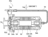
また、本発明の第3の態様に係る吸収ヒートポンプは、例えば図2に示すように、上記本発明の第1の態様又は第2の態様に係る吸収ヒートポンプ1(例えば図1参照)において、溶液ポンプ35pが、羽根車52pを回転させる電動機53mを収容するハウジング53を有し、吐出した流体の一部をハウジング53内に導入してハウジング53内を冷却するように構成され;希釈管58Bが、希溶液ライン16(例えば図1参照)内の希溶液Swをハウジング53内に導くように溶液ポンプ35pに接続されて構成されている。   Moreover, the absorption heat pump according to the third aspect of the present invention is a solution in the absorption heat pump 1 according to the first aspect or the second aspect of the present invention (see, for example, FIG. 1) as shown in FIG. The pump 35p has a housing 53 that houses an electric motor 53m that rotates the impeller 52p, and is configured to introduce a part of the discharged fluid into the housing 53 to cool the housing 53; The dilute solution Sw in the dilute solution line 16 (see, for example, FIG. 1) is connected to the solution pump 35p so as to guide it into the housing 53.

このように構成すると、比較的流路の断面積が小さく濃溶液が留まりがちな溶液ポンプの冷却系統内の濃溶液を希溶液で確実に希釈することができる。   If comprised in this way, the concentrated solution in the cooling system of the solution pump with which the cross-sectional area of a flow path is comparatively small and a concentrated solution tends to stay can be reliably diluted with a diluted solution.

また、本発明の第4の態様に係る吸収ヒートポンプは、例えば図2、図3に示すように、上記本発明の第2の態様に係る吸収ヒートポンプにおいて、溶液ポンプ35pが、羽根車52pを回転させる電動機53mを収容するハウジング53を有し、吐出した流体の一部をハウジング53内に導入してハウジング53内を冷却するように構成され;蒸発器20の下部に貯留された冷媒液Vfをハウジング53内に導く溶液ポンプ希釈管58B’をさらに備える。   Moreover, the absorption heat pump which concerns on the 4th aspect of this invention is the absorption heat pump which concerns on the said 2nd aspect of this invention, for example, as shown to FIG. 2, FIG. 3, The solution pump 35p rotates the impeller 52p. A housing 53 that houses an electric motor 53m to be introduced, and a part of the discharged fluid is introduced into the housing 53 to cool the inside of the housing 53; the refrigerant liquid Vf stored in the lower part of the evaporator 20 is A solution pump dilution pipe 58B ′ leading into the housing 53 is further provided.

このように構成すると、比較的流路の断面積が小さく濃溶液が留まりがちな溶液ポンプの冷却系統内の濃溶液を冷媒液で確実に希釈することができる。   If comprised in this way, the concentrated solution in the cooling system of the solution pump with which the cross-sectional area of a flow path is comparatively small and a concentrated solution tends to stay can be reliably diluted with a refrigerant liquid.

また、本発明の第5の態様に係る吸収ヒートポンプは、例えば図1に示すように、上記本発明の第1の態様乃至第4の態様のいずれか1つの態様に係る吸収ヒートポンプ1において、再生器30で発生した冷媒蒸気Vgを導入し冷却し凝縮させる凝縮器40と;凝縮器40内に存在する不凝縮ガスNgを凝縮器40内から抜き出す抽気流路64、66と;抽気流路64、66を介して抜き出された不凝縮ガスNgを集める抽気タンク62と;再生器30から導出された濃溶液Saを抽気タンク62に導く抽気溶液流路65、66と;抽気タンク62内の吸収溶液Saを再生器30に導く戻り溶液流路67と;希溶液ライン16を流れる希溶液Swを抽気タンク62へ導く希溶液抽気希釈管68とを備え;濃溶液Saを抽気溶液流路65、66を介して抽気タンク62に搬送することにより凝縮器40内から抽気流路64、66を介して抽気タンク62へ不凝縮ガスNgを抜き出すように構成されている。   In addition, the absorption heat pump according to the fifth aspect of the present invention is regenerated in the absorption heat pump 1 according to any one of the first to fourth aspects of the present invention as shown in FIG. A condenser 40 for introducing and cooling and condensing the refrigerant vapor Vg generated in the condenser 30; and extraction passages 64 and 66 for extracting the non-condensable gas Ng existing in the condenser 40 from the condenser 40; , 66, an extraction tank 62 that collects the non-condensable gas Ng extracted through 66; an extraction solution flow path 65, 66 that guides the concentrated solution Sa derived from the regenerator 30 to the extraction tank 62; A return solution flow path 67 for introducing the absorption solution Sa to the regenerator 30; a dilute solution extraction pipe 68 for introducing the dilute solution Sw flowing through the dilute solution line 16 to the extraction tank 62; and a extraction solution flow path 65 for the concentrated solution Sa. 66 Via is configured to extract the non-condensable gas Ng to extraction tank 62 through the bleed passage 64, 66 from the condenser 40 within by conveying the gas extraction tank 62.

このように構成すると、濃溶液を抽気タンクに搬送することで不凝縮ガスを抽気する抽気系統内の吸収溶液を希溶液で希釈することができる。   If comprised in this way, the absorption solution in the extraction system which extracts a non-condensable gas by conveying a concentrated solution to an extraction tank can be diluted with a dilute solution.

また、本発明の第6の態様に係る吸収ヒートポンプは、例えば図3に示すように、上記本発明の第2の態様又は第4の態様に係る吸収ヒートポンプにおいて、再生器30で発生した冷媒蒸気Vgを導入し冷却し凝縮させる凝縮器40と;凝縮器40内に存在する不凝縮ガスNgを凝縮器40内から抜き出す抽気流路64、66と;抽気流路64、66を介して抜き出された不凝縮ガスNgを集める抽気タンク62と;再生器30から導出された濃溶液Saを抽気タンク62に導く抽気溶液流路65、66と;抽気タンク62内の吸収溶液Saを再生器30に導く戻り溶液流路67と;蒸発器20の下部に貯留された冷媒液Vfを抽気タンク62へ導く冷媒液抽気希釈管68Aとを備え;濃溶液Saを抽気溶液流路65、66を介して抽気タンク62に搬送することにより凝縮器40内から抽気流路64、66を介して抽気タンク62へ不凝縮ガスNgを抜き出すように構成されている。   Moreover, the absorption heat pump which concerns on the 6th aspect of this invention is the refrigerant | coolant vapor | steam which generate | occur | produced in the regenerator 30 in the absorption heat pump which concerns on the said 2nd aspect or 4th aspect of this invention, for example, as shown in FIG. A condenser 40 that introduces Vg, cools and condenses; and extraction passages 64 and 66 for extracting non-condensable gas Ng existing in the condenser 40 from the condenser 40; and extraction through the extraction passages 64 and 66. An extraction tank 62 for collecting the non-condensed gas Ng; extraction solution flow paths 65 and 66 for guiding the concentrated solution Sa derived from the regenerator 30 to the extraction tank 62; and an absorption solution Sa in the extraction tank 62 for the regenerator 30 A return solution flow path 67 for guiding the refrigerant liquid Vf stored in the lower part of the evaporator 20 to the extraction tank 62; a concentrated solution Sa through the extraction solution flow paths 65 and 66; Extraction tongue 62 is configured to extract the non-condensable gas Ng to extraction tank 62 through the bleed passage 64, 66 from the condenser 40 within the transport to.

このように構成すると、濃溶液を抽気タンクに搬送することで不凝縮ガスを抽気する抽気系統内の吸収溶液を冷媒液で希釈することができる。   If comprised in this way, the absorption solution in the extraction system which extracts non-condensable gas by conveying a concentrated solution to an extraction tank can be diluted with a refrigerant | coolant liquid.

また、本発明の第7の態様に係る吸収ヒートポンプは、例えば図1に示すように、上記本発明の第1の態様乃至第6の態様のいずれか1つの態様に係る吸収ヒートポンプ1において、溶液ポンプ35pで吐出された濃溶液Saが流れる方向を順方向として、溶液ポンプ35pの吐出側の濃溶液ライン35に設けられた逆流制限手段35cであって、逆方向に流れる流体の流量を溶液ポンプ35pに損傷を与えない流量に制限する逆流制限手段35cを備える。   Moreover, the absorption heat pump according to the seventh aspect of the present invention is the solution of the absorption heat pump 1 according to any one of the first to sixth aspects of the present invention as shown in FIG. The reverse flow restricting means 35c provided in the concentrated solution line 35 on the discharge side of the solution pump 35p, with the flow direction of the concentrated solution Sa discharged by the pump 35p as the forward direction, There is provided a backflow restricting means 35c for restricting the flow rate so as not to damage 35p.

このように構成すると、溶液ポンプが停止した際に吸収器と再生器との圧力差及び位置ヘッドにより生ずる濃溶液ライン内の吸収溶液の逆流によって溶液ポンプが損傷することを防ぐことができる。   If comprised in this way, when a solution pump stops, it can prevent that a solution pump is damaged by the backflow of the absorption solution in the concentrated solution line which arises by the pressure difference of an absorber and a regenerator, and a position head.

また、本発明の第8の態様に係る吸収ヒートポンプは、例えば図6に示すように、上記本発明の第1の態様乃至第7の態様のいずれか1つの態様に係る吸収ヒートポンプにおいて、濃溶液ライン35内の濃溶液Saと希溶液ライン16内の希溶液Swとで熱交換させる溶液熱交換器38であって、導入された濃溶液Sa及び希溶液Swが再生器30の下部に貯留される濃溶液Saの停止中の液位よりも高所に位置するように設けられた溶液熱交換器38を備える。   Moreover, the absorption heat pump according to the eighth aspect of the present invention is the concentrated heat solution according to any one of the first to seventh aspects of the present invention as shown in FIG. The solution heat exchanger 38 exchanges heat between the concentrated solution Sa in the line 35 and the diluted solution Sw in the diluted solution line 16, and the introduced concentrated solution Sa and diluted solution Sw are stored below the regenerator 30. The solution heat exchanger 38 is provided so as to be positioned higher than the liquid level during the stop of the concentrated solution Sa.

このように構成すると、溶液ポンプが停止した際に吸収器と再生器との圧力差及び位置ヘッドにより濃溶液ライン内の吸収溶液が逆流したときに、濃溶液が溶液熱交換器から導出されるので、溶液熱交換器内で吸収溶液が結晶することを回避することができる。   With this configuration, when the absorption pump in the concentrated solution line flows backward due to the pressure difference between the absorber and the regenerator and the position head when the solution pump is stopped, the concentrated solution is led out from the solution heat exchanger. Therefore, it is possible to avoid the absorption solution from being crystallized in the solution heat exchanger.

また、本発明の第9の態様に係る吸収ヒートポンプは、例えば図6に示すように、上記本発明の第1の態様乃至第7の態様のいずれか1つの態様に係る吸収ヒートポンプにおいて、濃溶液ライン35内の濃溶液Saと希溶液ライン16内の希溶液Swとで熱交換させる溶液熱交換器38を備え;希釈管58A’が、溶液熱交換器38よりも上流側の希溶液ライン16と溶液熱交換器38よりも下流側の濃溶液ライン35とを連絡するように接続されている。   In addition, the absorption heat pump according to the ninth aspect of the present invention is the concentrated heat pump according to any one of the first to seventh aspects of the present invention as shown in FIG. A solution heat exchanger 38 for exchanging heat between the concentrated solution Sa in the line 35 and the diluted solution Sw in the diluted solution line 16; the dilution pipe 58A ′ is disposed upstream of the diluted solution line 16 from the solution heat exchanger 38; And the concentrated solution line 35 on the downstream side of the solution heat exchanger 38 are connected to each other.

このように構成すると、希釈管から濃溶液ラインに合流した希溶液が再生器に向かって流れる際に濃溶液を溶液熱交換器から押し出すこととなり、溶液熱交換器内に濃溶液が滞留することを回避することができる。   With this configuration, the concentrated solution is pushed out of the solution heat exchanger when the dilute solution joined from the dilution pipe to the concentrated solution line flows toward the regenerator, and the concentrated solution stays in the solution heat exchanger. Can be avoided.

本発明によれば、希溶液ライン内の希溶液を濃溶液ライン内に導く希釈管であって、希溶液ライン側から濃溶液ライン側への希溶液の流れを許し、濃溶液ライン側から希溶液ライン側への溶液ポンプで圧送された濃溶液の流れを遮断する逆流防止手段を有する希釈管を備えるので、吸収溶液の希釈運転が完了する前に溶液ポンプを運転することができなくなった場合でも希溶液を濃溶液に混合させることができて濃溶液を希釈することができ、濃溶液が結晶することを安定的に回避することができる。   According to the present invention, a dilution pipe that guides a dilute solution in a dilute solution line into the concentrated solution line, allowing the flow of the dilute solution from the dilute solution line side to the concentrated solution line side, and diluting from the concentrated solution line side. When equipped with a dilution tube with backflow prevention means that blocks the flow of concentrated solution pumped by the solution pump to the solution line side, the solution pump cannot be operated before the absorption solution dilution operation is completed However, the dilute solution can be mixed with the concentrated solution, the concentrated solution can be diluted, and the concentrated solution can be stably prevented from crystallizing.

以下、図面を参照して本発明の実施の形態について説明する。なお、各図において互いに同一又は相当する部材には同一あるいは類似の符号を付し、重複した説明は省略する。   Embodiments of the present invention will be described below with reference to the drawings. In the drawings, the same or similar members are denoted by the same or similar reference numerals, and redundant description is omitted.

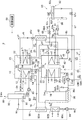
まず図1を参照して、本発明の第1の実施の形態に係る吸収ヒートポンプ1を説明する。図1は、吸収ヒートポンプ1の模式的系統図である。吸収ヒートポンプ1は、吸収ヒートポンプサイクルを行う主要構成機器である吸収器10、蒸発器20、再生器30、及び凝縮器40と、希溶液Swを吸収器10から再生器30に導く希溶液ラインとしての希溶液管16と、濃溶液Saを再生器30から吸収器10に導く濃溶液ラインとしての濃溶液管35及び溶液ポンプ35pと、希溶液管16内の希溶液Swを濃溶液管35に導く希釈管としての流路希釈管58A及び溶液ポンプ35pに導く希釈管としてのポンプ希釈管58Bと、制御装置99とを備えている。吸収ヒートポンプ1は、比較的利用価値の低い低温(例えば80℃〜90℃程度)の排温水を熱源媒体として再生器30及び蒸発器20に供給して、利用価値の高い蒸気(例えば、圧力が約0.1MPa(ゲージ圧)を超え、望ましくは0.8MPa(ゲージ圧)程度)を気液分離器80から取り出すことができるものである。   First, an absorption heat pump 1 according to a first embodiment of the present invention will be described with reference to FIG. FIG. 1 is a schematic system diagram of the absorption heat pump 1. The absorption heat pump 1 includes an absorber 10, an evaporator 20, a regenerator 30, and a condenser 40 that are main components that perform an absorption heat pump cycle, and a dilute solution line that guides the dilute solution Sw from the absorber 10 to the regenerator 30. The diluted solution tube 16, the concentrated solution tube 35 as a concentrated solution line for introducing the concentrated solution Sa from the regenerator 30 to the absorber 10, the solution pump 35 p, and the diluted solution Sw in the diluted solution tube 16 into the concentrated solution tube 35. A flow path dilution pipe 58A as a dilution pipe for guiding, a pump dilution pipe 58B as a dilution pipe leading to the solution pump 35p, and a control device 99 are provided. The absorption heat pump 1 supplies low temperature (for example, about 80 ° C. to 90 ° C.) waste water having relatively low utility value as a heat source medium to the regenerator 30 and the evaporator 20, and steam having high utility value (for example, pressure is increased). A pressure exceeding about 0.1 MPa (gauge pressure), desirably about 0.8 MPa (gauge pressure)) can be taken out from the gas-liquid separator 80.

なお、以下の説明においては、吸収溶液に関し、ヒートポンプサイクル上における区別を容易にするために、性状やヒートポンプサイクル上の位置に応じて「希溶液Sw」や「濃溶液Sa」等と呼称するが、性状等を不問にするときは総称して「吸収溶液S」又は「溶液S」ということとする。同様に、冷媒に関し、ヒートポンプサイクル上における区別を容易にするために、性状やヒートポンプサイクル上の位置に応じて「蒸発器冷媒蒸気Ve」、「再生器冷媒蒸気Vg」、「冷媒液Vf」等と呼称するが、性状等を不問にするときは総称して「冷媒V」ということとする。本実施の形態では、吸収溶液S(吸収剤と冷媒Vとの混合物)としてLiBr水溶液が用いられており、冷媒Vとして水(HO)が用いられている。また、被加熱媒体Wは、液体の被加熱媒体Wである被加熱媒体液Wq、気体の被加熱媒体である被加熱媒体蒸気Wv、被加熱媒体液Wqと被加熱媒体蒸気Wvとが混合した混合被加熱媒体Wmの総称である。本実施の形態では、被加熱媒体Wとして水(HO)が用いられている。 In the following description, the absorption solution is referred to as “dilute solution Sw”, “concentrated solution Sa” or the like depending on the properties and the position on the heat pump cycle in order to facilitate the distinction on the heat pump cycle. When the properties are not questioned, they are collectively referred to as “absorbing solution S” or “solution S”. Similarly, in order to easily distinguish the refrigerant on the heat pump cycle, “evaporator refrigerant vapor Ve”, “regenerator refrigerant vapor Vg”, “refrigerant liquid Vf”, etc., depending on the properties and positions on the heat pump cycle. However, when the properties and the like are not asked, they are collectively referred to as “refrigerant V”. In the present embodiment, an LiBr aqueous solution is used as the absorbing solution S (a mixture of the absorbent and the refrigerant V), and water (H 2 O) is used as the refrigerant V. The heated medium W is a heated medium liquid Wq which is a liquid heated medium W, a heated medium vapor Wv which is a gaseous heated medium, and the heated medium liquid Wq and the heated medium vapor Wv are mixed. A general term for the mixed medium Wm to be heated. In the present embodiment, water (H 2 O) is used as the heating medium W.

吸収器10は、被加熱媒体Wの流路を構成する加熱管11と、濃溶液Saを散布する濃溶液散布ノズル12を内部に有している。濃溶液散布ノズル12は、散布した濃溶液Saが加熱管11に降りかかるように、加熱管11の上方に配設されている。吸収器10は、濃溶液散布ノズル12から濃溶液Saが散布され、濃溶液Saが蒸発器冷媒蒸気Veを吸収する際に吸収熱を発生させる。この吸収熱を、加熱管11を流れる被加熱媒体Wが受熱して、被加熱媒体Wが加熱されるように構成されている。吸収器10の下部には、散布された濃溶液Saが蒸発器冷媒蒸気Veを吸収して濃度が低下した希溶液Swが貯留される貯留部13が形成されている。加熱管11は、希溶液Swに没入しないように、貯留部13よりも上方に配設されている。このようにすると、加熱管11の表面に濡れ広がった濃溶液Saに蒸発器冷媒蒸気Veが吸収されるようになるため、濃溶液Saと蒸発器冷媒蒸気Veとの接触面積を大きくできると共に、発生した吸収熱が加熱管11を流れる被加熱媒体Wに速やかに伝わり、吸収能力の回復を早めることができる。貯留部13には、貯留された希溶液Swの液位を検出する吸収器液位検出器14が配設されている。   The absorber 10 includes a heating tube 11 that forms a flow path of the medium to be heated W and a concentrated solution spray nozzle 12 that sprays the concentrated solution Sa. The concentrated solution spray nozzle 12 is disposed above the heating tube 11 so that the sprayed concentrated solution Sa falls on the heating tube 11. The absorber 10 generates heat of absorption when the concentrated solution Sa is sprayed from the concentrated solution spray nozzle 12 and the concentrated solution Sa absorbs the evaporator refrigerant vapor Ve. The heated medium W flowing through the heating tube 11 receives this absorbed heat so that the heated medium W is heated. In the lower part of the absorber 10, a storage part 13 is formed in which the diluted solution Sa that has been dispersed absorbs the evaporator refrigerant vapor Ve to store the diluted solution Sw having a reduced concentration. The heating tube 11 is disposed above the storage unit 13 so as not to be immersed in the dilute solution Sw. In this way, the evaporator refrigerant vapor Ve is absorbed by the concentrated solution Sa wetted and spread on the surface of the heating tube 11, so that the contact area between the concentrated solution Sa and the evaporator refrigerant vapor Ve can be increased, The generated absorption heat is quickly transmitted to the heated medium W flowing through the heating tube 11, and the recovery of the absorption capacity can be accelerated. The storage unit 13 is provided with an absorber liquid level detector 14 that detects the liquid level of the stored diluted solution Sw.

蒸発器20は、熱源媒体としての熱源温水hの流路を構成する熱源管21と、冷媒液Vfを散布する冷媒液散布ノズル22を内部に有している。冷媒液散布ノズル22は、散布した冷媒液Vfが熱源管21に降りかかるように、熱源管21の上方に配設されている。冷媒液散布ノズル22は、凝縮器40内の冷媒液Vfを蒸発器20に導く冷媒液管45と接続されている。蒸発器20は、冷媒液散布ノズル22から冷媒液Vfが散布され、散布された冷媒液Vfが熱源管21内を流れる熱源温水hの熱で蒸発して蒸発器冷媒蒸気Veが発生するように構成されている。蒸発器20は、散布された冷媒液Vfのうち蒸発しなかった冷媒液Vfが下部に貯留されるように構成されている。熱源管21は、典型的には、下部に貯留された冷媒液Vfに浸らないように配設されている。蒸発器20の下部には、貯留された冷媒液Vfの液位を検出する蒸発器液位検出器24が配設されている。蒸発器液位検出器24は、冷媒液管45に配設された二方弁45vと信号ケーブルで接続されており、検出した冷媒液Vfの液位に応じて蒸発器20に導入する冷媒液Vfの流量を調節することができるように構成されている。蒸発器20の底部には、貯留されている冷媒液Vfを凝縮器40に戻す冷媒液管25と、冷媒液Vfを吸収器10の貯留部13に導く連通管28が接続されている。冷媒液管25には、冷媒熱交換器48が配設されている。連通管28には、電気が供給されているときに閉となり、電気の供給が遮断されているときに開となる自動弁としての電磁弁29が配設されている。電磁弁29は、いわゆるノーマリオープンの電磁弁である。   The evaporator 20 includes therein a heat source pipe 21 that forms a flow path of a heat source hot water h as a heat source medium, and a refrigerant liquid spray nozzle 22 that sprays the refrigerant liquid Vf. The refrigerant liquid spray nozzle 22 is disposed above the heat source pipe 21 so that the sprayed refrigerant liquid Vf falls on the heat source pipe 21. The refrigerant liquid spray nozzle 22 is connected to a refrigerant liquid pipe 45 that guides the refrigerant liquid Vf in the condenser 40 to the evaporator 20. In the evaporator 20, the refrigerant liquid Vf is sprayed from the refrigerant liquid spray nozzle 22, and the sprayed refrigerant liquid Vf is evaporated by the heat of the heat source hot water h flowing in the heat source pipe 21 to generate the evaporator refrigerant vapor Ve. It is configured. The evaporator 20 is configured such that the refrigerant liquid Vf that has not evaporated out of the dispersed refrigerant liquid Vf is stored in the lower part. The heat source pipe 21 is typically arranged so as not to be immersed in the refrigerant liquid Vf stored in the lower part. An evaporator liquid level detector 24 that detects the liquid level of the stored refrigerant liquid Vf is disposed below the evaporator 20. The evaporator liquid level detector 24 is connected to a two-way valve 45v disposed in the refrigerant liquid pipe 45 by a signal cable, and the refrigerant liquid introduced into the evaporator 20 according to the detected liquid level of the refrigerant liquid Vf. The flow rate of Vf can be adjusted. Connected to the bottom of the evaporator 20 are a refrigerant liquid pipe 25 that returns the stored refrigerant liquid Vf to the condenser 40 and a communication pipe 28 that guides the refrigerant liquid Vf to the storage section 13 of the absorber 10. A refrigerant heat exchanger 48 is disposed in the refrigerant liquid pipe 25. The communication pipe 28 is provided with an electromagnetic valve 29 as an automatic valve that closes when electricity is supplied and opens when the supply of electricity is interrupted. The solenoid valve 29 is a so-called normally open solenoid valve.

吸収器10と蒸発器20とは、相互に連通するように1つの缶胴内に形成されている。吸収器10と蒸発器20とが連通することにより、蒸発器20で発生した蒸発器冷媒蒸気Veを吸収器10に供給することができるように構成されている。吸収器10と蒸発器20とは、典型的には、濃溶液散布ノズル12より上方及び冷媒液散布ノズル22より上方で連通している。また、蒸発器20は、連通管28を介して吸収器10内の吸収溶液Sが蒸発器20内に流入しないように、蒸発器20の底面が吸収器10の貯留部13の液面よりも高くなるように配設されている。換言すれば、連通管28は、吸収器10との接続部よりも蒸発器20との接続部の方が高所に位置するように構成されている。   The absorber 10 and the evaporator 20 are formed in one can body so as to communicate with each other. By connecting the absorber 10 and the evaporator 20, the evaporator refrigerant vapor Ve generated in the evaporator 20 can be supplied to the absorber 10. The absorber 10 and the evaporator 20 typically communicate with each other above the concentrated solution spray nozzle 12 and above the refrigerant liquid spray nozzle 22. Further, the evaporator 20 has a bottom surface of the evaporator 20 that is lower than the liquid level of the storage unit 13 of the absorber 10 so that the absorbing solution S in the absorber 10 does not flow into the evaporator 20 via the communication pipe 28. It arrange | positions so that it may become high. In other words, the communication pipe 28 is configured such that the connection portion with the evaporator 20 is positioned higher than the connection portion with the absorber 10.

再生器30は、希溶液Swを加熱する熱源媒体としての熱源温水hを内部に流す熱源管31と、希溶液Swを散布する希溶液散布ノズル32とを有している。再生器30は、散布された希溶液Swから冷媒Vが蒸発して濃度が上昇した濃溶液Saが下部に貯留されるように構成されている。再生器30では、希溶液Swが熱源温水hに加熱されることにより、濃溶液Saと再生器冷媒蒸気Vgとが生成されるように構成されている。再生器30の濃溶液Saが貯留される部分と吸収器10の濃溶液散布ノズル12とは、濃溶液Saを流す濃溶液管35で接続されている。濃溶液管35には、再生器30の濃溶液Saを吸収器10に圧送する溶液ポンプ35pが配設されている。溶液ポンプ35pは、吸収器液位検出器14と信号ケーブルで接続されたインバータ35vを有しており、吸収器液位検出器14が検出する液位に応じて回転速度が調節されて吸収器10に圧送する濃溶液Saの流量を調節することができるように構成されている。希溶液散布ノズル32と吸収器10の貯留部13とは希溶液Swを流す希溶液管16で接続されている。濃溶液管35及び希溶液管16には、濃溶液Saと希溶液Swとの間で熱交換を行わせる溶液熱交換器38が配設されている。   The regenerator 30 has a heat source pipe 31 for flowing heat source hot water h as a heat source medium for heating the dilute solution Sw, and a dilute solution spray nozzle 32 for spraying the dilute solution Sw. The regenerator 30 is configured such that a concentrated solution Sa whose concentration is increased by evaporation of the refrigerant V from the sprayed diluted solution Sw is stored in the lower part. The regenerator 30 is configured such that the concentrated solution Sa and the regenerator refrigerant vapor Vg are generated by heating the dilute solution Sw to the heat source hot water h. A portion where the concentrated solution Sa of the regenerator 30 is stored and the concentrated solution spray nozzle 12 of the absorber 10 are connected by a concentrated solution pipe 35 through which the concentrated solution Sa flows. The concentrated solution tube 35 is provided with a solution pump 35p that pumps the concentrated solution Sa of the regenerator 30 to the absorber 10. The solution pump 35p has an inverter 35v connected to the absorber liquid level detector 14 by a signal cable, and the rotational speed is adjusted according to the liquid level detected by the absorber liquid level detector 14, and the absorber. The flow rate of the concentrated solution Sa to be pumped to 10 can be adjusted. The dilute solution spray nozzle 32 and the storage unit 13 of the absorber 10 are connected by a dilute solution tube 16 through which the dilute solution Sw flows. The concentrated solution tube 35 and the diluted solution tube 16 are provided with a solution heat exchanger 38 that performs heat exchange between the concentrated solution Sa and the diluted solution Sw.

ここで図2を参照して、溶液ポンプ35pの構造について説明する。溶液ポンプ35pは、機外から供給された電力で稼働する遠心式のキャンドモータポンプであり、羽根車52pを収容するケーシング52と、電動機53mを収容するハウジング53とを有している。電動機53mは、ロータ53rと、ロータ53rを囲むように配設されたステータ53sとを有している。ロータ53rと羽根車52pとは軸受け54bに支持された軸54を介して接続されており、ロータ53rの回転により羽根車52pを回転させることができるように構成されている。また、溶液ポンプ35pは、羽根車52pの回転によって吐出された流体(本実施の形態では濃溶液Sa)の一部を、ケーシング52からハウジング53の反ケーシング52側に導く冷却用管55を有している。冷却用管55を流れる流体は、ハウジング53内に流入し、ロータ53rとステータ53sとの間を通ってケーシング52内の羽根車52p部分に到達するように構成されている。このように流体が流れることにより、電動機53m及び軸受け54bを冷却することができるように構成されている。冷却用管55には、ポンプ希釈管58Bが接続されている。   Here, the structure of the solution pump 35p will be described with reference to FIG. The solution pump 35p is a centrifugal canned motor pump that operates with electric power supplied from outside the apparatus, and includes a casing 52 that houses an impeller 52p and a housing 53 that houses an electric motor 53m. The electric motor 53m includes a rotor 53r and a stator 53s disposed so as to surround the rotor 53r. The rotor 53r and the impeller 52p are connected via a shaft 54 supported by a bearing 54b, and the impeller 52p can be rotated by the rotation of the rotor 53r. Further, the solution pump 35p has a cooling pipe 55 that guides a part of the fluid (concentrated solution Sa in the present embodiment) discharged by the rotation of the impeller 52p from the casing 52 to the side opposite to the casing 52 of the housing 53. is doing. The fluid flowing through the cooling pipe 55 flows into the housing 53, passes between the rotor 53r and the stator 53s, and reaches the impeller 52p portion in the casing 52. Thus, it is comprised so that the electric motor 53m and the bearing 54b can be cooled by the fluid flowing. A pump dilution pipe 58 </ b> B is connected to the cooling pipe 55.

再び図1に戻って吸収ヒートポンプ1の構成の説明を続ける。凝縮器40は、冷却媒体流路を形成する冷却水管41を有している。冷却水管41には、冷却媒体としての冷却水cが流れる。凝縮器40は、再生器30で発生した再生器冷媒蒸気Vgを導入し、これを冷却水cで冷却して凝縮させるように構成されている。冷却水管41は、再生器冷媒蒸気Vgを直接冷却することができるように、再生器冷媒蒸気Vgが凝縮した冷媒液Vfに浸らないように配設されている。凝縮器40には凝縮した冷媒液Vfを蒸発器20に送る冷媒液管45が接続されている。冷媒液管45には、冷媒液Vfを蒸発器20に圧送するための冷媒ポンプ46と、蒸発器20から凝縮器40に向かう冷媒液Vfと凝縮器40から蒸発器20に向かう冷媒液Vfとで熱交換を行わせる冷媒熱交換器48と、蒸発器20への冷媒液Vfの供給を調節する二方弁45vとが、冷媒液Vfの流れる方向にこの順で配設されている。   Returning to FIG. 1 again, the description of the configuration of the absorption heat pump 1 will be continued. The condenser 40 has a cooling water pipe 41 that forms a cooling medium flow path. The cooling water c as a cooling medium flows through the cooling water pipe 41. The condenser 40 is configured to introduce the regenerator refrigerant vapor Vg generated in the regenerator 30, cool it with the cooling water c, and condense it. The cooling water pipe 41 is disposed so that the regenerator refrigerant vapor Vg is not immersed in the condensed refrigerant liquid Vf so that the regenerator refrigerant vapor Vg can be directly cooled. The condenser 40 is connected to a refrigerant liquid pipe 45 that sends the condensed refrigerant liquid Vf to the evaporator 20. The refrigerant liquid pipe 45 includes a refrigerant pump 46 for pumping the refrigerant liquid Vf to the evaporator 20, a refrigerant liquid Vf going from the evaporator 20 to the condenser 40, and a refrigerant liquid Vf going from the condenser 40 to the evaporator 20. The refrigerant heat exchanger 48 that performs heat exchange in the above and the two-way valve 45v that regulates the supply of the refrigerant liquid Vf to the evaporator 20 are arranged in this order in the direction in which the refrigerant liquid Vf flows.

再生器30と凝縮器40とは、相互に連通するように1つの缶胴内に形成されている。再生器30と凝縮器40とが連通することにより、再生器30で発生した再生器冷媒蒸気Vgを凝縮器40に供給することができるように構成されている。再生器30と凝縮器40とは、典型的には、希溶液散布ノズル32より上方で連通している。また、再生器30の下部と凝縮器40の下部とは、凝縮器40内の冷媒液Vfが所定の液位よりも上昇しようとしたときに冷媒液Vfを再生器30に導くオーバーフロー管44で接続されている。オーバーフロー管44は、凝縮器40側では、凝縮器40の底部を貫通して内部に立ち上げられ、端部が所定の液位に位置するように配設されている。また、再生器30の下部と凝縮器40の下部とは、ノーマリオープンの電磁弁47vが配設された連絡管47で接続されている。連絡管47は、再生器30側ではオーバーフロー管44を介して冷媒液Vfを再生器30に流入させることができるようにオーバーフロー管44に接続され、凝縮器40側ではオーバーフロー管44の立ち上がり高さよりも低い位置に管端が位置するように配設されている。吸収器10と再生器30とは、不凝縮ガス移動管15を介して連通可能に構成されている。不凝縮ガス移動管15は、吸収器10内に生じた不凝縮ガスNgを再生器30に移動させることができるように、吸収器10の気相部と再生器30の気相部とを連通している。不凝縮ガス移動管15には、連通を遮断する遮断弁15vが配設されている。また、吸収器10及び蒸発器20が再生器30及び凝縮器40よりも高所に配設されており、位置ヘッドで吸収器10内の吸収溶液Sを再生器30へ及び蒸発器20内の冷媒液Vfを凝縮器40へそれぞれ搬送可能に構成されている。   The regenerator 30 and the condenser 40 are formed in one can body so as to communicate with each other. By connecting the regenerator 30 and the condenser 40, the regenerator refrigerant vapor Vg generated in the regenerator 30 can be supplied to the condenser 40. The regenerator 30 and the condenser 40 typically communicate with each other above the dilute solution spray nozzle 32. The lower part of the regenerator 30 and the lower part of the condenser 40 are an overflow pipe 44 that guides the refrigerant liquid Vf to the regenerator 30 when the refrigerant liquid Vf in the condenser 40 is about to rise above a predetermined liquid level. It is connected. On the condenser 40 side, the overflow pipe 44 passes through the bottom of the condenser 40 and rises inside, and is arranged so that the end is positioned at a predetermined liquid level. The lower part of the regenerator 30 and the lower part of the condenser 40 are connected by a communication pipe 47 provided with a normally open electromagnetic valve 47v. The connecting pipe 47 is connected to the overflow pipe 44 so that the refrigerant liquid Vf can flow into the regenerator 30 via the overflow pipe 44 on the regenerator 30 side, and from the rising height of the overflow pipe 44 on the condenser 40 side. Also, the pipe end is disposed at a lower position. The absorber 10 and the regenerator 30 are configured to communicate with each other via the non-condensable gas moving pipe 15. The non-condensable gas moving tube 15 communicates the gas phase part of the absorber 10 and the gas phase part of the regenerator 30 so that the non-condensable gas Ng generated in the absorber 10 can be moved to the regenerator 30. is doing. The non-condensable gas moving pipe 15 is provided with a shutoff valve 15v that cuts off communication. Further, the absorber 10 and the evaporator 20 are disposed higher than the regenerator 30 and the condenser 40, and the absorbing solution S in the absorber 10 is transferred to the regenerator 30 and in the evaporator 20 by the position head. Each of the refrigerant liquids Vf is configured to be able to be conveyed to the condenser 40.

流路希釈管58Aは、溶液熱交換器38と希溶液散布ノズル32との間の希溶液管16と、溶液ポンプ35pと溶液熱交換器38との間の濃溶液管35とに接続されており、希溶液管16と濃溶液管35とを連絡している。流路希釈管58Aには、逆流防止手段としてのチェッキ弁59Aが設けられている。チェッキ弁59Aは、メカニカルな構造で流体の逆流を防止するように構成されており、希溶液管16から濃溶液管35への希溶液Swの流れを許し、濃溶液管35から希溶液管16への濃溶液Saの流れを遮断するように配設されている。流路希釈管58Aの接続部分と溶液熱交換器38との間の濃溶液管35には、逆流制限手段としての有孔チェッキ弁35cが設けられている。有孔チェッキ弁35cは、流体の逆流を防ぐための弁体に小孔が形成されており、所定流量の流体の逆流を許す点で一般的なチェッキ弁(逆止弁)と異なっている点以外は一般的なチェッキ弁(逆止弁)と同じ構造になっている。有孔チェッキ弁35cが逆流を許す所定の流量は、流体の逆流によって溶液ポンプ35pの羽根車52p(図2参照)が回転させられることにより溶液ポンプ35pが損傷することを回避することができる範囲内でできるだけ多い流量である。有孔チェッキ弁35cは、吸収器10側から再生器30側への吸収溶液Sが上記の逆流を許す所定の流量となるように配設されている。   The flow path dilution pipe 58A is connected to the dilute solution pipe 16 between the solution heat exchanger 38 and the dilute solution spray nozzle 32 and the concentrated solution pipe 35 between the solution pump 35p and the solution heat exchanger 38. The dilute solution tube 16 and the concentrated solution tube 35 communicate with each other. The flow path dilution pipe 58A is provided with a check valve 59A as a backflow prevention means. The check valve 59A has a mechanical structure and is configured to prevent the backflow of fluid. The check valve 59A allows the dilute solution Sw to flow from the dilute solution tube 16 to the dilute solution tube 35. It arrange | positions so that the flow of the concentrated solution Sa to may be interrupted | blocked. The concentrated solution pipe 35 between the connection portion of the flow path dilution pipe 58A and the solution heat exchanger 38 is provided with a perforated check valve 35c as a backflow restricting means. The perforated check valve 35c is different from a general check valve (check valve) in that a small hole is formed in a valve body for preventing a back flow of fluid, and a back flow of a fluid having a predetermined flow rate is allowed. Other than that, it has the same structure as a general check valve (check valve). The predetermined flow rate at which the perforated check valve 35c allows reverse flow is a range in which the solution pump 35p can be prevented from being damaged by rotating the impeller 52p (see FIG. 2) of the solution pump 35p by the reverse flow of the fluid. The flow rate is as high as possible. The perforated check valve 35c is disposed so that the absorbing solution S from the absorber 10 side to the regenerator 30 side has a predetermined flow rate that allows the above-described reverse flow.

ポンプ希釈管58Bは、流路希釈管58Aの接続部分よりも下流側の希溶液管16と、溶液ポンプ35pの冷却用管55(図2参照)とに接続されており、希溶液管16内の希溶液Swを溶液ポンプ35pのハウジング53(図2参照)内に導入することができるように構成されている。ポンプ希釈管58Bには、通電時に閉となり電気の供給が遮断されているときに開となる電磁弁59B(ノーマリオープンの電磁弁)が配設されている。   The pump dilution pipe 58B is connected to the dilute solution pipe 16 downstream of the connection part of the flow path dilution pipe 58A and the cooling pipe 55 (see FIG. 2) of the solution pump 35p. The dilute solution Sw can be introduced into the housing 53 (see FIG. 2) of the solution pump 35p. The pump dilution pipe 58B is provided with a solenoid valve 59B (normally open solenoid valve) that is closed when energized and opened when the supply of electricity is interrupted.

吸収ヒートポンプ1は、気液分離器80と、抽気系統60とをさらに備えている。気液分離器80は、吸収器10の加熱管11を流れて加熱された被加熱媒体Wを導入し、被加熱媒体蒸気Wvと被加熱媒体液Wqとを分離する機器である。気液分離器80には、内部に貯留する被加熱媒体液Wqの液位を検出する気液分離器液位検出器81が設けられている。気液分離器80の下部と吸収器10の加熱管11の一端とは、被加熱媒体液Wqを加熱管11に導く被加熱媒体液管82で接続されている。被加熱媒体液管82には、被加熱媒体液Wqを加熱管11に向けて圧送する被加熱媒体ポンプ83が配設されている。内部が気相部となる気液分離器80の側面と加熱管11の他端とは、加熱された被加熱媒体Wを気液分離器80に導く加熱後被加熱媒体管84で接続されている。   The absorption heat pump 1 further includes a gas-liquid separator 80 and an extraction system 60. The gas-liquid separator 80 is a device that introduces the heated medium W that flows through the heating tube 11 of the absorber 10 and separates the heated medium vapor Wv and the heated medium liquid Wq. The gas-liquid separator 80 is provided with a gas-liquid separator liquid level detector 81 that detects the liquid level of the heated medium liquid Wq stored inside. The lower part of the gas-liquid separator 80 and one end of the heating pipe 11 of the absorber 10 are connected by a heated medium liquid pipe 82 that guides the heated medium liquid Wq to the heating pipe 11. The heated medium liquid pipe 82 is provided with a heated medium pump 83 that pumps the heated medium liquid Wq toward the heated pipe 11. The side surface of the gas-liquid separator 80 whose inside is a gas phase portion and the other end of the heating tube 11 are connected by a heated medium tube 84 after heating that guides the heated medium W to the gas-liquid separator 80. Yes.

また、気液分離器80には、蒸気として系外に供給された分の被加熱媒体Wを補うための補給水Wsを系外から導入する補給水管85が接続されている。補給水管85には、気液分離器80に向けて補給水Wsを圧送する補給水ポンプ86と、逆止弁85cと、補給水Wsを温水で予熱する補給水熱交換器87Bと、希溶液Swと熱交換させて補給水Wsをさらに加熱する補給水熱交換器87Aとが、補給水Wsの流れ方向に向かってこの順に配設されている。補給水ポンプ86は、気液分離器液位検出器81と信号ケーブルで接続されており、気液分離器80内の被加熱媒体液Wqの液位に応じて発停が制御されるように構成されている。補給水熱交換器87Aは、補給水Wsと希溶液Swとを熱交換させるように、補給水管85及び溶液熱交換器38よりも上流側の希溶液管16に配設されている。また、気液分離器80には、被加熱媒体蒸気Wvを系外に供給する被加熱媒体蒸気供給管89が上部(典型的には頂部)に接続されている。   The gas-liquid separator 80 is connected to a makeup water pipe 85 that introduces makeup water Ws for supplementing the heated medium W supplied to the outside of the system as steam from outside the system. The make-up water pipe 85 includes a make-up water pump 86 for pumping make-up water Ws toward the gas-liquid separator 80, a check valve 85c, a make-up water heat exchanger 87B for preheating the make-up water Ws with warm water, and a dilute solution. A make-up water heat exchanger 87A that further heats the make-up water Ws by exchanging heat with Sw is arranged in this order toward the flow direction of the make-up water Ws. The make-up water pump 86 is connected to the gas-liquid separator liquid level detector 81 through a signal cable so that the start / stop is controlled according to the liquid level of the heated medium liquid Wq in the gas-liquid separator 80. It is configured. The make-up water heat exchanger 87A is disposed in the dilute solution pipe 16 upstream of the make-up water pipe 85 and the solution heat exchanger 38 so as to exchange heat between the make-up water Ws and the dilute solution Sw. Further, the heated liquid vapor supply pipe 89 for supplying the heated medium vapor Wv to the outside of the system is connected to the upper part (typically the top) of the gas-liquid separator 80.

気液分離器80は、加熱管11内で被加熱媒体液Wqの一部が蒸発して被加熱媒体液Wqと被加熱媒体蒸気Wvとが混合した混合被加熱媒体Wmを導入してもよく、被加熱媒体液Wqのまま気液分離器80に導いて減圧し一部を気化させて混合被加熱媒体Wmとしたものを気液分離させるようにしてもよい。被加熱媒体液Wqを減圧気化するには、オリフィス等の絞り手段を用いることができる。加熱管11内で被加熱媒体液Wqの一部を蒸発させるか否かは、典型的には、被加熱媒体ポンプ83及び/又は補給水ポンプ86の吐出圧力を調節することにより、加熱管11内の圧力を被加熱媒体液Wqの温度に相当する飽和圧力よりも高くするか否かによって調節することができる。   The gas-liquid separator 80 may introduce a mixed heated medium Wm in which part of the heated medium liquid Wq is evaporated in the heating tube 11 and the heated medium liquid Wq and the heated medium vapor Wv are mixed. Alternatively, the heated medium liquid Wq may be guided to the gas-liquid separator 80, and the pressure may be reduced to partially vaporize the mixed heated medium Wm for gas-liquid separation. In order to vaporize the medium to be heated Wq under reduced pressure, a throttle means such as an orifice can be used. Whether or not a part of the heated medium liquid Wq is evaporated in the heating pipe 11 is typically determined by adjusting the discharge pressure of the heated medium pump 83 and / or the make-up water pump 86. The internal pressure can be adjusted by whether or not the internal pressure is higher than a saturation pressure corresponding to the temperature of the heated medium liquid Wq.

抽気系統60は、エジェクタ61と抽気タンク62とを有している。エジェクタ61は、駆動源としての濃溶液Saを減圧して加速させるノズル(不図示)と、吸引物としての不凝縮ガスNgを導入する導入口61aとを有している。エジェクタ61の導入口61aには、抽気流路を構成する凝縮器抽気管64が接続されている。凝縮器抽気管64には、流体の流れを遮断する抽気逆流防止弁としての凝縮器抽気遮断弁64vが配設されている。凝縮器抽気遮断弁64vには、典型的にはノーマリオープンの電磁弁が用いられるが、手動の弁や、エジェクタ61側から凝縮器40側への流体の流れを遮断する逆止弁(チェッキ弁)が用いられてもよい。エジェクタ61のノズルの吸い込み側には、溶液ポンプ35pと有孔チェッキ弁35cとの間で濃溶液管35から分岐した抽気溶液流路を構成する駆動溶液供給管65が接続されている。エジェクタ61のノズルの吐出側には、駆動源の濃溶液Saと吸引物の不凝縮ガスNgとの混合流体を抽気タンク62へと導く抽気溶液流路を構成する気液混合管66が接続されている。つまり、抽気溶液流路は、再生器30から駆動溶液供給管65の接続部までの濃溶液管35と、駆動溶液供給管65と、気液混合管66とで構成されている。また、溶液ポンプ35pは、再生器30の濃溶液Saを吸収器10に圧送するポンプであると共に、再生器30の濃溶液Saを抽気タンク62に圧送する抽気溶液ポンプを兼ねている。抽気溶液ポンプとして機能する溶液ポンプ35pは、典型的には、再生器30内の吸収溶液Sを大気圧以上に昇圧できるヘッドを持つように構成されている。   The extraction system 60 includes an ejector 61 and an extraction tank 62. The ejector 61 has a nozzle (not shown) that depressurizes and accelerates the concentrated solution Sa as a drive source, and an inlet 61a that introduces a non-condensable gas Ng as an aspirated material. A condenser bleed pipe 64 that constitutes a bleed flow path is connected to the inlet 61 a of the ejector 61. The condenser bleeder pipe 64 is provided with a condenser bleeder shutoff valve 64v as a bleeder backflow prevention valve that shuts off the fluid flow. Typically, a normally open solenoid valve is used as the condenser bleed-off valve 64v. However, a manual valve or a check valve (checker) that shuts off the flow of fluid from the ejector 61 side to the condenser 40 side is used. Valve) may be used. Connected to the suction side of the nozzle of the ejector 61 is a drive solution supply pipe 65 that constitutes an extraction solution flow path branched from the concentrated solution pipe 35 between the solution pump 35p and the perforated check valve 35c. Connected to the discharge side of the nozzle of the ejector 61 is a gas-liquid mixing tube 66 that constitutes an extraction solution flow path that guides the mixed fluid of the concentrated solution Sa of the driving source and the non-condensable gas Ng of the suction material to the extraction tank 62. ing. That is, the extraction solution flow path is constituted by the concentrated solution pipe 35 from the regenerator 30 to the connection portion of the drive solution supply pipe 65, the drive solution supply pipe 65, and the gas-liquid mixing pipe 66. The solution pump 35p is a pump that pumps the concentrated solution Sa of the regenerator 30 to the absorber 10 and also serves as an extraction solution pump that pumps the concentrated solution Sa of the regenerator 30 to the extraction tank 62. The solution pump 35p that functions as a bleed solution pump is typically configured to have a head that can raise the absorption solution S in the regenerator 30 to atmospheric pressure or higher.

抽気タンク62は、駆動源の濃溶液Saと吸引物の不凝縮ガスNgとを導入し、捕集した不凝縮ガスNgを溜めておくことができるタンクである。抽気タンク62は、天板に気体溜まり62cが形成されており、気体溜まり62cの上部に不凝縮ガスNgを導出する導出弁62vが設けられている。気体溜まり62cにはフロート62fが設けられており、抽気タンク62内の濃溶液Saの液位の上昇と共にフロート62fが上昇することにより、不凝縮ガスNgを機外に排出する排出口を閉塞するように構成されている。抽気タンク62の底部には、気液混合管66が接続されている。気液混合管66は、液トラップを形成するように、下に凸のU字状に配設されている。抽気タンク62の底部にはまた、抽気タンク62内の濃溶液Saを再生器30に戻す戻り溶液流路を構成する戻り溶液管67が接続されている。戻り溶液管67には、濃溶液Saの流れを遮断する戻り溶液遮断弁67v(ノーマリオープンの電磁弁)が配設されている。戻り溶液管67もまた、液トラップを形成するように、抽気タンク62の底部及び再生器30の底部よりも下方へ一旦下がるように配設されている。抽気タンク62の天板には、希溶液抽気希釈管68の一端が接続されている。希溶液抽気希釈管68の他端は、吸収器10近傍の希溶液管16に接続されており、希溶液管16を流れる希溶液Swを抽気タンク62へ流入させることができるように構成されている。希溶液抽気希釈管68には、通電時に閉となり電気の供給が遮断されているときに開となる電磁弁69(ノーマリオープンの電磁弁)が配設されている。   The extraction tank 62 is a tank that can introduce the concentrated solution Sa of the driving source and the non-condensable gas Ng of the sucked material and store the collected non-condensable gas Ng. In the extraction tank 62, a gas reservoir 62c is formed on the top plate, and a derivation valve 62v for deriving the non-condensable gas Ng is provided above the gas reservoir 62c. The gas reservoir 62c is provided with a float 62f. The float 62f rises as the liquid level of the concentrated solution Sa in the extraction tank 62 rises, thereby closing the discharge port for discharging the noncondensable gas Ng to the outside of the apparatus. It is configured as follows. A gas-liquid mixing pipe 66 is connected to the bottom of the extraction tank 62. The gas-liquid mixing tube 66 is disposed in a U-shape projecting downward so as to form a liquid trap. Also connected to the bottom of the extraction tank 62 is a return solution pipe 67 that constitutes a return solution flow path for returning the concentrated solution Sa in the extraction tank 62 to the regenerator 30. The return solution pipe 67 is provided with a return solution cutoff valve 67v (normally open electromagnetic valve) that blocks the flow of the concentrated solution Sa. The return solution pipe 67 is also disposed so as to be temporarily lowered below the bottom of the extraction tank 62 and the bottom of the regenerator 30 so as to form a liquid trap. One end of a diluted solution extraction dilution pipe 68 is connected to the top plate of the extraction tank 62. The other end of the diluted solution extraction pipe 68 is connected to the diluted solution pipe 16 in the vicinity of the absorber 10, and is configured to allow the diluted solution Sw flowing in the diluted solution pipe 16 to flow into the extraction tank 62. Yes. The diluted solution extraction pipe 68 is provided with a solenoid valve 69 (normally open solenoid valve) that is closed when energized and opened when the supply of electricity is interrupted.

制御装置99は、吸収ヒートポンプ1の運転を制御する機器である。制御装置99は、冷媒ポンプ46及び被加熱媒体ポンプ83とそれぞれ信号ケーブルで接続されており、これらの発停や回転速度の調節を行うことができるように構成されている。これまでの説明では吸収器液位検出器14の出力を直接入力して制御されることとした溶液ポンプ35p、及び気液分離器液位検出器81の出力を直接入力して制御されることとした補給水ポンプ86も、制御装置99を介して(検出器の出力信号を一旦制御装置99に入力して)制御されることとしてもよい。また、制御装置99は、遮断弁15v、電磁弁29、電磁弁47v、電磁弁59B、凝縮器抽気遮断弁64v、戻り溶液遮断弁67v、電磁弁69にそれぞれ信号を送信して弁の開閉動作をさせることができるように構成されている。これまでの説明では蒸発器液位検出器24の出力を直接入力して制御されることとした二方弁45vも、制御装置99を介して(検出器の出力信号を一旦制御装置99に入力して)制御されることとしてもよい。   The control device 99 is a device that controls the operation of the absorption heat pump 1. The control device 99 is connected to the refrigerant pump 46 and the heated medium pump 83 through signal cables, respectively, and is configured to be able to start / stop and adjust the rotation speed. In the description so far, the output of the absorber liquid level detector 14 is directly input and controlled, and the solution pump 35p and the output of the gas-liquid separator liquid level detector 81 are directly input and controlled. The make-up water pump 86 may be controlled via the control device 99 (the detector output signal is temporarily input to the control device 99). Further, the control device 99 sends signals to the shutoff valve 15v, the solenoid valve 29, the solenoid valve 47v, the solenoid valve 59B, the condenser bleed shutoff valve 64v, the return solution shutoff valve 67v, and the solenoid valve 69 to open and close the valves. It is comprised so that it can be made. In the description so far, the two-way valve 45v that is controlled by directly inputting the output of the evaporator liquid level detector 24 is also input to the control device 99 via the control device 99 (the output signal of the detector is once input to the control device 99). It may be controlled).

上述のノーマリオープンの電磁弁29、47v、59B、69、及び凝縮器抽気遮断弁64v、戻り溶液遮断弁67vは、溶液ポンプ35pに電気が供給されなくなると併せて電気の供給が遮断されるように構成されており、典型的には、溶液ポンプ35pに接続される電気ケーブルが接続された分電盤を介して機外から電気の供給を受ける(典型的には、溶液ポンプ35p及び各電磁弁29、47v、59B、69、64v、67v共に商用電源から電力の供給を受ける)ように構成されている。   The normally open solenoid valves 29, 47v, 59B, 69, the condenser bleeder shutoff valve 64v, and the return solution shutoff valve 67v are shut off when electricity is not supplied to the solution pump 35p. Typically, electricity is supplied from outside the machine via a distribution board to which an electric cable connected to the solution pump 35p is connected (typically, the solution pump 35p and each The solenoid valves 29, 47v, 59B, 69, 64v, and 67v are configured to receive power from a commercial power source).

引き続き図1を参照して、吸収ヒートポンプ1の作用を説明する。吸収ヒートポンプ1の被加熱媒体Wを昇温する運転中は、各電磁弁29、47v、59B、69に電気が供給されており、各電磁弁29、47v、59B、69は閉になっている。まず、冷媒側のサイクルを説明する。凝縮器40では、再生器30で蒸発した再生器冷媒蒸気Vgを受け入れて、冷却水管41を流れる冷却水cで冷却して凝縮し、冷媒液Vfとする。凝縮した冷媒液Vfは、冷媒ポンプ46で蒸発器20の冷媒液散布ノズル22に送られる。このとき、蒸発器20の下部に貯留される冷媒液Vfが所定の液位になるように、蒸発器液位検出器24の検出液位に応じて二方弁45vが制御される。冷媒液散布ノズル22に送られた冷媒液Vfは、熱源管21に向けて散布され、熱源管21内を流れる熱源温水hによって加熱され、蒸発して蒸発器冷媒蒸気Veとなる。蒸発器20で発生した蒸発器冷媒蒸気Veは、蒸発器20と連通する吸収器10へと移動する。凝縮器40内の冷媒液Vfが所定の液位を超える場合は、超える分の冷媒液Vfがオーバーフロー管44を介して再生器30に移動する。これにより、吸収ヒートポンプ1の運転中の吸収溶液Sの濃度が結晶しない濃度に維持される。   With continued reference to FIG. 1, the operation of the absorption heat pump 1 will be described. During operation of heating the heated medium W of the absorption heat pump 1, electricity is supplied to the electromagnetic valves 29, 47v, 59B, 69, and the electromagnetic valves 29, 47v, 59B, 69 are closed. . First, the refrigerant side cycle will be described. In the condenser 40, the regenerator refrigerant vapor Vg evaporated in the regenerator 30 is received, cooled and condensed with the cooling water c flowing through the cooling water pipe 41, and the refrigerant liquid Vf is obtained. The condensed refrigerant liquid Vf is sent to the refrigerant liquid spray nozzle 22 of the evaporator 20 by the refrigerant pump 46. At this time, the two-way valve 45v is controlled according to the detected liquid level of the evaporator liquid level detector 24 so that the refrigerant liquid Vf stored in the lower part of the evaporator 20 becomes a predetermined liquid level. The refrigerant liquid Vf sent to the refrigerant liquid spraying nozzle 22 is sprayed toward the heat source pipe 21, heated by the heat source hot water h flowing through the heat source pipe 21, and evaporated to become the evaporator refrigerant vapor Ve. The evaporator refrigerant vapor Ve generated in the evaporator 20 moves to the absorber 10 that communicates with the evaporator 20. When the refrigerant liquid Vf in the condenser 40 exceeds a predetermined liquid level, the excess refrigerant liquid Vf moves to the regenerator 30 via the overflow pipe 44. Thereby, the density | concentration of the absorption solution S during operation | movement of the absorption heat pump 1 is maintained at the density | concentration which does not crystallize.

次に吸収ヒートポンプ1の溶液側のサイクルを説明する。吸収器10では、濃溶液Saが濃溶液散布ノズル12から散布され、この散布された濃溶液Saが蒸発器20から移動してきた蒸発器冷媒蒸気Veを吸収する。蒸発器冷媒蒸気Veを吸収した濃溶液Saは、濃度が低下して希溶液Swとなる。吸収器10では、濃溶液Saが蒸発器冷媒蒸気Veを吸収する際に吸収熱が発生する。この吸収熱により、加熱管11を流れる被加熱媒体液Wqが加熱される。ここで、被加熱媒体蒸気Wvを取り出すための気液分離器80まわりの作用について説明する。   Next, the cycle on the solution side of the absorption heat pump 1 will be described. In the absorber 10, the concentrated solution Sa is sprayed from the concentrated solution spray nozzle 12, and the sprayed concentrated solution Sa absorbs the evaporator refrigerant vapor Ve that has moved from the evaporator 20. The concentrated solution Sa that has absorbed the evaporator refrigerant vapor Ve is reduced in concentration to become a diluted solution Sw. In the absorber 10, heat of absorption is generated when the concentrated solution Sa absorbs the evaporator refrigerant vapor Ve. The absorbed medium liquid Wq flowing through the heating tube 11 is heated by the absorbed heat. Here, the operation around the gas-liquid separator 80 for taking out the heated medium vapor Wv will be described.

気液分離器80には、系外から補給水Wsが補給水管85を介して導入される。補給水Wsは、補給水ポンプ86により補給水管85を圧送され、まず補給水熱交換器87Bで温度が上昇した後に、補給水熱交換器87Aで希溶液Swと熱交換してさらに温度が上昇して、気液分離器80に導入される。気液分離器80に導入された補給水Wsは、被加熱媒体液Wqとして気液分離器80の下部に貯留される。気液分離器80の下部に貯留される被加熱媒体液Wqが所定の液位になるように、補給水ポンプ86が制御される。気液分離器80の下部に貯留されている被加熱媒体液Wqは、被加熱媒体ポンプ83で吸収器10の加熱管11に送られる。加熱管11に送られた被加熱媒体液Wqは、吸収器10における上述の吸収熱により加熱される。加熱管11で加熱された被加熱媒体液Wqは、一部が蒸発して被加熱媒体蒸気Wvとなった混合被加熱媒体Wmとして、あるいは温度が上昇した被加熱媒体液Wqとして、気液分離器80に向けて加熱後被加熱媒体管84を流れる。加熱後被加熱媒体管84を、温度が上昇した被加熱媒体液Wqが流れる場合、被加熱媒体液Wqは、気液分離器80に導入される際に減圧され、一部が蒸発して被加熱媒体蒸気Wvとなった混合被加熱媒体Wmとして気液分離器80に導入される。気液分離器80に導入された混合被加熱媒体Wmは、被加熱媒体液Wqと被加熱媒体蒸気Wvとが分離される。分離された被加熱媒体液Wqは、気液分離器80の下部に貯留され、再び吸収器10の加熱管11に送られる。他方、分離された被加熱媒体蒸気Wvは、被加熱媒体蒸気供給管89に導出され、蒸気利用場所に供給される。   The gas-liquid separator 80 is introduced with makeup water Ws from outside the system via a makeup water pipe 85. The make-up water Ws is pumped through the make-up water pipe 85 by the make-up water pump 86. After the temperature rises first in the make-up water heat exchanger 87B, the temperature is further raised by exchanging heat with the dilute solution Sw in the make-up water heat exchanger 87A. Then, it is introduced into the gas-liquid separator 80. The makeup water Ws introduced into the gas-liquid separator 80 is stored in the lower part of the gas-liquid separator 80 as the heated medium liquid Wq. The makeup water pump 86 is controlled so that the heated medium liquid Wq stored in the lower part of the gas-liquid separator 80 becomes a predetermined liquid level. The heated medium liquid Wq stored in the lower part of the gas-liquid separator 80 is sent to the heating pipe 11 of the absorber 10 by the heated medium pump 83. The heated medium liquid Wq sent to the heating tube 11 is heated by the absorption heat described above in the absorber 10. The heated medium liquid Wq heated by the heating tube 11 is gas-liquid separated as a mixed heated medium Wm partially evaporated to become a heated medium vapor Wv, or as a heated medium liquid Wq whose temperature has increased. Flows through the heated medium tube 84 after heating toward the vessel 80. When the heated medium liquid Wq whose temperature has risen flows through the heated medium pipe 84 after heating, the heated medium liquid Wq is depressurized when being introduced into the gas-liquid separator 80, and a part of the heated medium liquid Wq is evaporated and covered. The mixed medium to be heated Wm that has become the heating medium vapor Wv is introduced into the gas-liquid separator 80. In the mixed heated medium Wm introduced into the gas-liquid separator 80, the heated medium liquid Wq and the heated medium vapor Wv are separated. The separated heated medium liquid Wq is stored in the lower part of the gas-liquid separator 80 and sent to the heating tube 11 of the absorber 10 again. On the other hand, the separated heated medium vapor Wv is led out to the heated medium vapor supply pipe 89 and supplied to the vapor use place.

再び吸収ヒートポンプ1の溶液側のサイクルの説明に戻る。吸収器10で蒸発器冷媒蒸気Veを吸収した濃溶液Saは、濃度が低下して希溶液Swとなり、貯留部13に貯留される。貯留部13内の希溶液Swは、重力及び吸収器10と再生器30との内圧の差により再生器30に向かって希溶液管16を流れ、補給水熱交換器87Aで補給水Wsと熱交換して温度が低下した後に、溶液熱交換器38で濃溶液Saと熱交換してさらに温度が低下して、再生器30に至る。このとき、溶液ポンプ35pの吐出圧力がチェッキ弁59Aにかかっているので、また、電磁弁59Bが閉になっているので、希溶液Swは流路希釈管58Aを介して及びポンプ希釈管58Bを介して濃溶液管35に流入することなく再生器30に達する。再生器30に送られた希溶液Swは、希溶液散布ノズル32から散布される。希溶液散布ノズル32から散布された希溶液Swは、熱源管31を流れる熱源温水h(本実施の形態では約80℃前後)によって加熱され、散布された希溶液Sw中の冷媒が蒸発して濃溶液Saとなり、再生器30の下部に貯留される。他方、希溶液Swから蒸発した冷媒Vは再生器冷媒蒸気Vgとして凝縮器40へと移動する。再生器30の下部に貯留された濃溶液Saは、溶液ポンプ35pにより、濃溶液管35を介して吸収器10の濃溶液散布ノズル12に圧送される。このとき、流路希釈管58Aにはチェッキ弁59Aが配設されているため流路希釈管58Aを介して濃溶液Saが希溶液管16に流入することがなく、またポンプ希釈管58Bの電磁弁59Bが閉じられているのでポンプ希釈管58Bを介して濃溶液Saが希溶液管16に流入することがない。また、吸収器10の貯留部13に貯留された希溶液Swが所定の液位になるように、吸収器液位検出器14の検出液位に応じてインバータ35vにより溶液ポンプ35pの回転速度(ひいては吐出流量)が調節される。濃溶液管35を流れる濃溶液Saは、溶液熱交換器38で希溶液Swと熱交換して温度が上昇してから吸収器10に流入し、濃溶液散布ノズル12から散布される。以降、同様のサイクルを繰り返す。   Returning to the description of the cycle on the solution side of the absorption heat pump 1 again. The concentrated solution Sa that has absorbed the evaporator refrigerant vapor Ve by the absorber 10 is reduced in concentration to become the diluted solution Sw, and is stored in the storage unit 13. The dilute solution Sw in the storage unit 13 flows through the dilute solution pipe 16 toward the regenerator 30 due to gravity and a difference in internal pressure between the absorber 10 and the regenerator 30, and is supplied to the replenishing water heat exchanger 87A and the replenishing water Ws. After the exchange and the temperature is lowered, the solution heat exchanger 38 exchanges heat with the concentrated solution Sa to further lower the temperature and reach the regenerator 30. At this time, since the discharge pressure of the solution pump 35p is applied to the check valve 59A and the electromagnetic valve 59B is closed, the dilute solution Sw passes through the flow path dilution pipe 58A and the pump dilution pipe 58B. The regenerator 30 is reached without flowing into the concentrated solution tube 35 through the regenerator 30. The dilute solution Sw sent to the regenerator 30 is sprayed from the dilute solution spray nozzle 32. The dilute solution Sw sprayed from the dilute solution spray nozzle 32 is heated by the heat source hot water h (about 80 ° C. in this embodiment) flowing through the heat source pipe 31, and the refrigerant in the sprayed dilute solution Sw evaporates. It becomes a concentrated solution Sa and is stored in the lower part of the regenerator 30. On the other hand, the refrigerant V evaporated from the dilute solution Sw moves to the condenser 40 as a regenerator refrigerant vapor Vg. The concentrated solution Sa stored in the lower part of the regenerator 30 is pumped to the concentrated solution spray nozzle 12 of the absorber 10 through the concentrated solution tube 35 by the solution pump 35p. At this time, since the check valve 59A is provided in the flow path dilution pipe 58A, the concentrated solution Sa does not flow into the dilute solution pipe 16 via the flow path dilution pipe 58A, and the pump dilution pipe 58B has an electromagnetic wave. Since the valve 59B is closed, the concentrated solution Sa does not flow into the diluted solution tube 16 via the pump dilution tube 58B. Further, the rotation speed of the solution pump 35p (by the inverter 35v according to the detection liquid level of the absorber liquid level detector 14) so that the diluted solution Sw stored in the storage unit 13 of the absorber 10 becomes a predetermined liquid level ( As a result, the discharge flow rate) is adjusted. The concentrated solution Sa flowing through the concentrated solution pipe 35 is heat-exchanged with the diluted solution Sw by the solution heat exchanger 38 to rise in temperature, and then flows into the absorber 10 and is sprayed from the concentrated solution spray nozzle 12. Thereafter, the same cycle is repeated.

上記のような吸収溶液S及び冷媒Vのサイクルを行う吸収ヒートポンプ1は、吸収ヒートポンプサイクルを行う主要構成機器である吸収器10、蒸発器20、再生器30、及び凝縮器40の内部が大気圧以下であるため大気が侵入する場合がある。大気はその中でも低圧となる再生器30及び凝縮器40に侵入しやすい。また、吸収ヒートポンプ1は、缶胴を構成する鋼材が吸収溶液と反応して水素ガスが発生する。水素ガスは吸収ヒートポンプサイクル内で比較的高温となる吸収器10で多く発生する。大気や水素ガスは、吸収ヒートポンプサイクル内及び大気圧下で凝縮しない不凝縮ガスNgである。吸収器10内の不凝縮ガスNgは、制御装置99が遮断弁15vを定期的に開くことによってより低圧の再生器30に移動する。他方、再生器30で発生した再生器冷媒蒸気Vgが凝縮器40に移動することから、全体のガスの流れは再生器30から凝縮器40に向かっているので、再生器30内の不凝縮ガスNgは凝縮器40に収集される傾向にある。不凝縮ガスNgが吸収ヒートポンプ1内に滞留すると能力が低下するため、吸収ヒートポンプ1は、以下に説明するように内部の不凝縮ガスNgを抽気することとしている。   The absorption heat pump 1 that performs the cycle of the absorption solution S and the refrigerant V as described above includes an absorber 10, an evaporator 20, a regenerator 30, and a condenser 40 that are main components that perform the absorption heat pump cycle. The air may enter due to the following. The atmospheric air tends to enter the regenerator 30 and the condenser 40, which have a low pressure. In the absorption heat pump 1, the steel material constituting the can body reacts with the absorption solution to generate hydrogen gas. A large amount of hydrogen gas is generated in the absorber 10 that is relatively hot in the absorption heat pump cycle. Air and hydrogen gas are non-condensable gases Ng that do not condense in the absorption heat pump cycle and under atmospheric pressure. The non-condensable gas Ng in the absorber 10 moves to the lower pressure regenerator 30 when the control device 99 periodically opens the shut-off valve 15v. On the other hand, since the regenerator refrigerant vapor Vg generated in the regenerator 30 moves to the condenser 40, the entire gas flow is directed from the regenerator 30 toward the condenser 40, and thus the non-condensable gas in the regenerator 30. Ng tends to be collected in the condenser 40. When the non-condensable gas Ng stays in the absorption heat pump 1, the capacity is reduced. Therefore, the absorption heat pump 1 is configured to extract the internal non-condensable gas Ng as described below.

凝縮器40内の不凝縮ガスNgを抽気タンク62に収集する際は、導出弁62vが閉となっており、凝縮器抽気遮断弁64v及び戻り溶液遮断弁67vが開となっている。溶液ポンプ35pの作動により、再生器30内の濃溶液Saは、濃溶液管35を流れて吸収器10に圧送されると共に、一部が分流して駆動溶液供給管65に流入する。駆動溶液供給管65に流入した濃溶液Saは、溶液ポンプ35pの圧力により、エジェクタ61を通過し、気液混合管66を流れて抽気タンク62に流入する。濃溶液Saがエジェクタ61を通過することで、導入口61aに接続された凝縮器抽気管64を介して凝縮器40内の不凝縮ガスNgがエジェクタ61に吸引される。   When collecting the non-condensable gas Ng in the condenser 40 in the extraction tank 62, the outlet valve 62v is closed, and the condenser extraction cutoff valve 64v and the return solution cutoff valve 67v are open. By the operation of the solution pump 35p, the concentrated solution Sa in the regenerator 30 flows through the concentrated solution pipe 35 and is pumped to the absorber 10, and a part of the concentrated solution Sa flows into the driving solution supply pipe 65. The concentrated solution Sa flowing into the driving solution supply pipe 65 passes through the ejector 61 and flows through the gas-liquid mixing pipe 66 and into the extraction tank 62 due to the pressure of the solution pump 35p. As the concentrated solution Sa passes through the ejector 61, the non-condensable gas Ng in the condenser 40 is sucked into the ejector 61 through the condenser bleed pipe 64 connected to the inlet 61a.

抽気タンク62に流入した濃溶液Sa及び不凝縮ガスNgは、抽気タンク62内で気液分離される。つまり、濃溶液Saと不凝縮ガスNgとは液体と気体とに分離される。抽気タンク62内で分離された濃溶液Saは、戻り溶液管67を流れて再生器30に戻される。他方、抽気タンク62内で分離された不凝縮ガスNgは、導出弁62vが閉じられており、気液混合管66及び戻り溶液管67が液シール構造になっているため、抽気タンク62内に滞留する。このようにして、不凝縮ガスNgは抽気タンク62内に収集される。なお、吸収ヒートポンプ1の停止中で、濃溶液Saの流れが停止している状態でも、気液混合管66及び戻り溶液管67が液シール構造になっているため、不凝縮ガスNgは抽気タンク62内に保持される。   The concentrated solution Sa and the non-condensable gas Ng flowing into the extraction tank 62 are separated into gas and liquid in the extraction tank 62. That is, the concentrated solution Sa and the non-condensable gas Ng are separated into a liquid and a gas. The concentrated solution Sa separated in the extraction tank 62 flows through the return solution pipe 67 and is returned to the regenerator 30. On the other hand, the non-condensable gas Ng separated in the extraction tank 62 has the outlet valve 62v closed, and the gas-liquid mixing pipe 66 and the return solution pipe 67 have a liquid seal structure. Stay. In this way, the non-condensable gas Ng is collected in the extraction tank 62. Even when the absorption heat pump 1 is stopped and the flow of the concentrated solution Sa is stopped, the gas-liquid mixing tube 66 and the return solution tube 67 have a liquid seal structure, and therefore the non-condensable gas Ng is extracted from the extraction tank. 62.

抽気タンク62に収集された不凝縮ガスNgを抽気タンク62の外に排出する際は、制御装置99は、凝縮器抽気遮断弁64v及び戻り溶液遮断弁67vを閉にする。このとき、導出弁62vは閉じたままである。溶液ポンプ35pも作動している。すると、凝縮器40内の不凝縮ガスNgはエジェクタ61に吸引されないが、濃溶液Saは溶液ポンプ35pにより抽気タンク62に圧送される。これにより、抽気タンク62内の濃溶液Saの液位が上昇していき、抽気タンク62内の不凝縮ガスNgは圧縮される。そして、不凝縮ガスNgの圧力が大気圧以上となったら制御装置99は導出弁62vを開にする。導出弁62vが開になると、不凝縮ガスNgが導出弁62vを介して機外に排出される。このとき、抽気タンク62内の濃溶液Saの液位が上昇するが、濃溶液Saの液面の上昇と共に上昇するフロート62fが導出弁62vと連通する開口を塞ぐので、濃溶液Saが機外に流出することを防ぐことができる。フロート62fが導出弁62vと連通する開口を塞いだ場合は、抽気タンク62からの不凝縮ガスNgの導出も完了する。典型的には、上昇したフロート62fがスイッチ(不図示)を投入して、あるいは電極棒を利用した液面スイッチのような他の液面スイッチ(不図示)が作動して、制御装置99に信号を送信する構成としておくと、抽気タンク62からの不凝縮ガスNgの導出の完了を検出することができるので好ましい。あるいは、例えば制御装置99が導出弁62vを開にしてからの時間を計測し、あらかじめ測定しておいた不凝縮ガスNgの導出が完了するまでの時間に基づいて不凝縮ガスNgの導出の完了を検出してもよい。不凝縮ガスNgの導出が完了したら、制御装置99は、導出弁62vを閉じ、戻り溶液遮断弁67vを開放し、さらに凝縮器抽気遮断弁64vを開けて、凝縮器40内の不凝縮ガスNgの抽気タンク62への収集を再開する。   When discharging the non-condensable gas Ng collected in the extraction tank 62 to the outside of the extraction tank 62, the control device 99 closes the condenser extraction cutoff valve 64v and the return solution cutoff valve 67v. At this time, the outlet valve 62v remains closed. The solution pump 35p is also operating. Then, the non-condensable gas Ng in the condenser 40 is not sucked into the ejector 61, but the concentrated solution Sa is pumped to the extraction tank 62 by the solution pump 35p. Thereby, the liquid level of the concentrated solution Sa in the extraction tank 62 rises, and the non-condensable gas Ng in the extraction tank 62 is compressed. When the pressure of the non-condensable gas Ng becomes equal to or higher than the atmospheric pressure, the control device 99 opens the outlet valve 62v. When the outlet valve 62v is opened, the non-condensable gas Ng is discharged out of the machine via the outlet valve 62v. At this time, the liquid level of the concentrated solution Sa in the extraction tank 62 rises, but the float 62f that rises as the liquid level of the concentrated solution Sa rises closes the opening communicating with the outlet valve 62v. Can be prevented from leaking. When the float 62f blocks the opening communicating with the outlet valve 62v, the derivation of the non-condensable gas Ng from the extraction tank 62 is also completed. Typically, the raised float 62f turns on a switch (not shown), or another liquid level switch (not shown) such as a liquid level switch using an electrode rod is actuated to A configuration for transmitting a signal is preferable because completion of derivation of the non-condensable gas Ng from the extraction tank 62 can be detected. Alternatively, for example, the time after the control device 99 opens the derivation valve 62v is measured, and the derivation of the non-condensable gas Ng is completed based on the previously measured time until the derivation of the non-condensable gas Ng is completed. May be detected. When the derivation of the non-condensable gas Ng is completed, the control device 99 closes the derivation valve 62v, opens the return solution cutoff valve 67v, opens the condenser bleeder cutoff valve 64v, and sets the non-condensable gas Ng in the condenser 40. The collection into the extraction tank 62 is resumed.

上述のように作用する吸収ヒートポンプ1は、被加熱媒体Wを昇温する運転中、吸収溶液Sが、昇温された被加熱媒体Wの温度前後の温度で濃度を変化させながら吸収器10と再生器30とを循環して吸収ヒートポンプサイクルを継続させる。そして、吸収ヒートポンプ1の運転を停止する際は、濃度が高い濃溶液Saがそのままの濃度で周囲環境温度(例えば室温)に近づいて吸収溶液Sが結晶してしまい次に起動することができなくなることを回避するために、希釈運転が行われる。吸収ヒートポンプ1の希釈運転は、典型的には、まず被加熱媒体Wの昇温を停止したときに熱源管21、31への熱源温水hの供給を停止し、電磁弁29を開にして蒸発器20内の冷媒を吸収溶液Sに戻し、溶液ポンプ35pの運転を継続することで吸収器10及び再生器30並びにこれらを連絡する希溶液管16及び濃溶液管35内の吸収溶液Sの濃度を希釈すると共にほぼ均一にすることにより行われる。このとき、電磁弁29が希釈弁として機能することになるが、希釈運転時に電磁弁29に代えて電磁弁47vを開にして、凝縮器40内の冷媒を吸収溶液Sに戻すこととしてもよい。希釈弁として電磁弁47vを用いた場合は、連絡管47の立ち上がりの高さの設定により、サイクル濃度を考慮して必要な冷媒量を戻すことができる。なお、希釈弁として電磁弁29を利用し電磁弁47vを利用しない場合は、電磁弁47vを設けなくてよい。   The absorption heat pump 1 that operates as described above is configured so that the absorption solution S changes the concentration of the absorption solution S at a temperature around the temperature of the heated medium W while the temperature of the heated medium W is changed. The absorption heat pump cycle is continued by circulating through the regenerator 30. When the operation of the absorption heat pump 1 is stopped, the concentrated solution Sa having a high concentration approaches the ambient environment temperature (for example, room temperature) at the same concentration, and the absorption solution S crystallizes and cannot be started next. In order to avoid this, a dilution operation is performed. In the dilution operation of the absorption heat pump 1, typically, when the temperature rise of the medium to be heated W is stopped, the supply of the heat source hot water h to the heat source pipes 21 and 31 is stopped, and the electromagnetic valve 29 is opened to evaporate. The refrigerant in the vessel 20 is returned to the absorbing solution S, and the operation of the solution pump 35p is continued, whereby the absorber 10 and the regenerator 30 and the concentration of the absorbing solution S in the dilute solution pipe 16 and the concentrated solution pipe 35 that connect them. Is diluted and made almost uniform. At this time, the electromagnetic valve 29 functions as a dilution valve. However, the electromagnetic valve 47v may be opened instead of the electromagnetic valve 29 during the dilution operation, and the refrigerant in the condenser 40 may be returned to the absorbing solution S. . When the electromagnetic valve 47v is used as the dilution valve, the necessary refrigerant amount can be returned in consideration of the cycle concentration by setting the rising height of the communication pipe 47. When the electromagnetic valve 29 is used as a dilution valve and the electromagnetic valve 47v is not used, the electromagnetic valve 47v need not be provided.

吸収ヒートポンプ1の被加熱媒体Wを昇温する運転中あるいは希釈運転中に停電が生じた場合は、吸収溶液Sが十分希釈されないままの状態で溶液ポンプ35pが停止してしまい、このままの状態で周囲環境温度(例えば室温)に近づくと吸収溶液Sが結晶してしまうこととなる。吸収ヒートポンプと類似の装置構成を持ち溶液サイクルの圧力及び露点温度が異なる吸収冷凍機では、一般に被冷却媒体である冷水の出口温度を一定にする運転をしており、蒸発器の冷媒温度はほぼ一定になっている。このような吸収冷凍機では、吸収器に導入される冷却水の温度が低下した場合には吸収器内の吸収溶液の温度が低下するので、蒸発温度と吸収器溶液温度とが関係する吸収溶液濃度が低下する。このような吸収冷凍機では、温度が低下した際に吸収溶液の濃度が結晶濃度以上になるのは、一般に冷却水温度が高く外気温度も高い夏季の短期間であり、この夏季において停電等が発生して吸収溶液の希釈が不完全な状態で停止していたとしても、温度が低下して結晶が生じるまでには一般に数時間の余裕があり復電後の再起動で結晶が避けられることが多い。これに対し、吸収ヒートポンプ1は、典型的には被加熱媒体Wの出口温度をほぼ一定にする運転をするので、被加熱媒体Wを加熱する吸収器10内の吸収溶液Sの温度がほぼ一定の高温(昇温された被加熱媒体Wの温度をやや上回る温度)の状態になっている。吸収器10に供給される蒸発器冷媒蒸気Veは蒸発器20において熱源温水hで加熱されるため、蒸発器20内はほぼ一定温度になっており、冷却水cの温度が低下した場合でも蒸発温度と吸収器溶液温度とが関係する吸収溶液濃度は全負荷状態のままほぼ一定となる。つまり、吸収ヒートポンプ1は、典型的には、年間を通じて、温度が低下した際に吸収溶液の濃度が結晶濃度以上になる高濃度サイクルとなっており、停電等が生じて溶液ポンプ35pが稼働しなくなった場合は吸収溶液Sが結晶してしまう可能性が高い。吸収ヒートポンプ1は、このような不都合を回避すべく以下に示す作用をするように構成されている。   When a power failure occurs during the operation of raising the temperature of the heated medium W of the absorption heat pump 1 or during the dilution operation, the solution pump 35p stops in a state where the absorption solution S is not sufficiently diluted, and in this state. When approaching ambient temperature (for example, room temperature), absorption solution S will crystallize. Absorption refrigerators that have a device configuration similar to an absorption heat pump and differ in the pressure and dew point temperature of the solution cycle are generally operated to keep the outlet temperature of the cold water that is the cooling medium constant, and the refrigerant temperature of the evaporator is approximately It is constant. In such an absorption refrigerator, when the temperature of the cooling water introduced into the absorber decreases, the temperature of the absorption solution in the absorber decreases, so the absorption solution in which the evaporation temperature and the absorber solution temperature are related The concentration decreases. In such absorption refrigerators, when the temperature drops, the concentration of the absorbing solution exceeds the crystal concentration in the short period of summer when the cooling water temperature is high and the outside air temperature is high. Even if the absorption solution dilutes and stops incompletely, there is generally a few hours before the crystals drop and the temperature is reduced, and crystals can be avoided by restarting after power recovery There are many. On the other hand, the absorption heat pump 1 typically operates to make the outlet temperature of the heated medium W substantially constant, so that the temperature of the absorbent solution S in the absorber 10 that heats the heated medium W is substantially constant. Is at a high temperature (a temperature slightly higher than the temperature of the heated medium W). Since the evaporator refrigerant vapor Ve supplied to the absorber 10 is heated by the heat source hot water h in the evaporator 20, the inside of the evaporator 20 is at a substantially constant temperature, and evaporates even when the temperature of the cooling water c decreases. The absorbing solution concentration, which is related to the temperature and the absorber solution temperature, is substantially constant while maintaining the full load state. That is, the absorption heat pump 1 typically has a high concentration cycle in which the concentration of the absorption solution becomes equal to or higher than the crystal concentration when the temperature decreases throughout the year, and a power failure occurs and the solution pump 35p operates. When it disappears, there is a high possibility that the absorbing solution S will crystallize. The absorption heat pump 1 is configured to perform the following operation in order to avoid such inconvenience.

吸収ヒートポンプ1の被加熱媒体Wを昇温する運転中あるいは希釈運転中に停電等が生じて溶液ポンプ35pが停止した場合、吸収器10及び再生器30の内圧の差と位置ヘッドとにより、希溶液管16内の希溶液Sw及び濃溶液管35内の濃溶液Saの双方が吸収器10側から再生器30側へ向かって流れる。このとき、溶液ポンプ35pの吐出圧がチェッキ弁59Aにかからなくなっているので、希溶液管16内の希溶液Swが流路希釈管58Aを介して濃溶液管35に流入し、流入した希溶液Swが濃溶液管35内の濃溶液Saと混合して、濃溶液Saが希釈される。また、停電によりノーマリオープンの電磁弁59Bが開となり、ポンプ希釈管58Bを介して希溶液Swが溶液ポンプ35pのハウジング53内に流入して、ハウジング53内の濃溶液Saが希釈される。このように、吸収ヒートポンプ1では、濃溶液管35及び溶液ポンプ35p内の濃溶液Saが、吸収器10の貯留部13及び希溶液管16内に保有されている充分な量の希溶液Swで希釈されるため、希釈が不十分になることが抑制され、濃溶液Saが結晶することを安定的に回避することができる。   When a power failure or the like occurs during the operation of raising the temperature of the heated medium W of the absorption heat pump 1 or during the dilution operation, the solution pump 35p is stopped due to the difference in internal pressure between the absorber 10 and the regenerator 30 and the position head. Both the dilute solution Sw in the solution tube 16 and the concentrated solution Sa in the concentrated solution tube 35 flow from the absorber 10 side toward the regenerator 30 side. At this time, since the discharge pressure of the solution pump 35p is no longer applied to the check valve 59A, the dilute solution Sw in the dilute solution pipe 16 flows into the concentrated solution pipe 35 via the flow path diluting pipe 58A and flows into The solution Sw is mixed with the concentrated solution Sa in the concentrated solution tube 35 to dilute the concentrated solution Sa. Further, the normally open solenoid valve 59B is opened by a power failure, and the dilute solution Sw flows into the housing 53 of the solution pump 35p via the pump dilution pipe 58B, so that the concentrated solution Sa in the housing 53 is diluted. Thus, in the absorption heat pump 1, the concentrated solution Sa in the concentrated solution tube 35 and the solution pump 35 p is a sufficient amount of diluted solution Sw held in the storage unit 13 and the diluted solution tube 16 of the absorber 10. Since it is diluted, it is suppressed that dilution becomes insufficient, and it can avoid stably that concentrated solution Sa crystallizes.

なお、濃溶液管35には、溶液ポンプ35pの損傷を防ぐために有孔チェッキ弁35cが設けられているが、有孔チェッキ弁35cには小孔が形成されているため、溶液ポンプ35pの損傷を防止しつつ濃溶液Saを逆流させることができ、有孔チェッキ弁35cよりも吸収器10側に位置する濃溶液管35内の濃溶液Saを希釈することができる。このとき、吸収器10内の気体(典型的には蒸発器冷媒蒸気Ve)が希溶液管16を介して再生器30に抜けるよりも濃溶液管35を介して再生器30に抜ける方が早くなる大きさに有孔チェッキ弁35cの小孔の口径が形成されている場合は、再生器30から濃溶液散布ノズル12までの濃溶液Sa(濃溶液系の濃溶液Sa)を一時的にすべて再生器30に戻すことができる。濃溶液系の濃溶液Saがすべて再生器30に戻ると、希溶液管16を介して再生器30に流入した希溶液Swと混合して希釈され、希釈された吸収溶液Sが再び濃溶液管35に流入して、吸収器10及び再生器30の内圧がバランスする位置で吸収溶液Sが静止する。静止した吸収溶液Sは、結晶濃度未満に希釈されていることとなる。   The concentrated solution pipe 35 is provided with a perforated check valve 35c to prevent damage to the solution pump 35p. However, since the perforated check valve 35c has a small hole, damage to the solution pump 35p is caused. The concentrated solution Sa can be made to flow backward while preventing the concentrated solution Sa in the concentrated solution tube 35 located closer to the absorber 10 than the perforated check valve 35c. At this time, the gas in the absorber 10 (typically, the evaporator refrigerant vapor Ve) escapes to the regenerator 30 through the concentrated solution tube 35 faster than it escapes to the regenerator 30 through the dilute solution tube 16. If the small hole diameter of the perforated check valve 35c is formed to a certain size, all of the concentrated solution Sa (the concentrated solution system concentrated solution Sa) from the regenerator 30 to the concentrated solution spray nozzle 12 is temporarily removed. It can be returned to the regenerator 30. When all the concentrated solution system concentrated solution Sa returns to the regenerator 30, the diluted solution Sw is mixed with the diluted solution Sw flowing into the regenerator 30 through the diluted solution tube 16 and diluted, and the diluted absorption solution S is again concentrated solution tube. 35, the absorbent solution S stops at a position where the internal pressures of the absorber 10 and the regenerator 30 are balanced. The stationary absorption solution S is diluted to be less than the crystal concentration.

吸収ヒートポンプ1では、さらにノーマリオープンの電磁弁29が停電により開となり、蒸発器20の下部に貯留されていた冷媒液Vfが連通管28を介して貯留部13に流入し、貯留部13内の希溶液Swをさらに希釈する。貯留部13内の希溶液Swは濃溶液系の濃溶液Saを希釈するため、貯留部13内の希溶液Swの濃度が低下し及び量が増加することで、濃溶液系の濃溶液Saの希釈効果を向上させることができる。また、吸収ヒートポンプ1では、さらにノーマリオープンの電磁弁69が停電により開となり、希溶液管16内の希溶液Swが抽気タンク62に流入して、駆動溶液として導入された濃溶液Saを希釈する。駆動溶液供給管65、気液混合管66、及び戻り溶液管67は、これらを流れる濃溶液Saが吸収器10及び再生器30を循環する吸収溶液Sに比べて少量であるため口径が小さく、内部に濃溶液Saが滞留するとこの濃溶液Saが冷却されやすく結晶しやすい。吸収ヒートポンプ1は、抽気タンク62内の濃溶液Saが希釈されることにより、希釈された吸収溶液Sが、一部は気液混合管66及び駆動溶液供給管65を介して再生器30に流れ、その他は戻り溶液管67を介して再生器30に流れるため、駆動溶液供給管65、気液混合管66、及び戻り溶液管67内の吸収溶液Sを希釈することができ、吸収溶液Sの結晶を抑制することができる。   In the absorption heat pump 1, the normally open solenoid valve 29 is further opened due to a power failure, and the refrigerant liquid Vf stored in the lower part of the evaporator 20 flows into the storage unit 13 through the communication pipe 28 and enters the storage unit 13. Further dilute the dilute solution Sw. Since the dilute solution Sw in the storage unit 13 dilutes the concentrated solution system concentrated solution Sa, the concentration of the dilute solution Sw in the storage unit 13 decreases and the amount increases, thereby increasing the concentration of the concentrated solution system concentrated solution Sa. The dilution effect can be improved. Further, in the absorption heat pump 1, the normally open solenoid valve 69 is opened due to a power failure, and the dilute solution Sw in the dilute solution pipe 16 flows into the extraction tank 62 to dilute the concentrated solution Sa introduced as the drive solution. To do. The driving solution supply pipe 65, the gas-liquid mixing pipe 66, and the return solution pipe 67 have a small diameter because the concentrated solution Sa flowing therethrough is a small amount compared to the absorbing solution S circulating in the absorber 10 and the regenerator 30. When the concentrated solution Sa stays inside, the concentrated solution Sa is easily cooled and easily crystallized. In the absorption heat pump 1, when the concentrated solution Sa in the extraction tank 62 is diluted, a part of the diluted absorption solution S flows to the regenerator 30 through the gas-liquid mixing pipe 66 and the driving solution supply pipe 65. Others flow to the regenerator 30 via the return solution pipe 67, so that the absorbing solution S in the driving solution supply pipe 65, the gas-liquid mixing pipe 66, and the return solution pipe 67 can be diluted. Crystals can be suppressed.

次に図3を参照して、本発明の第2の実施の形態に係る吸収ヒートポンプ2を説明する。図3は、吸収ヒートポンプ2の模式的系統図である。吸収ヒートポンプ2の、吸収ヒートポンプ1(図1参照)との異なる点は、溶液ポンプ35p内に導入する流体を希溶液管16内の希溶液Swではなく蒸発器20内の冷媒液Vfとするように、ポンプ希釈管58B’の反溶液ポンプ35p側が蒸発器20の下部(典型的には底部)に接続されている。さらに、抽気タンク62に導入する流体を希溶液管16内の希溶液Swではなく蒸発器20内の冷媒液Vfとするように、希溶液抽気希釈管68に代えて冷媒液抽気希釈管68Aが蒸発器20の下部(典型的には底部)と抽気タンク62とを連絡するように設けられている。吸収ヒートポンプ2のその他の構成は、吸収ヒートポンプ1(図1参照)と同様である。吸収ヒートポンプ2では、冷媒液Vfを溶液ポンプ35p及び抽気タンク62に導入することとしているので、吸収溶液Sの流路断面積が小さく比較的結晶が生じやすいこれらの部分の吸収溶液Sを、効率よく希釈することができる。なお、吸収ヒートポンプ2では、溶液ポンプ35p及び抽気タンク62の双方に冷媒液Vfを導入することとしているが、冷媒液Vfを導入するのをいずれか一方とし、他方を吸収ヒートポンプ1(図1参照)のように希溶液Swを導入するように構成してもよい。   Next, an absorption heat pump 2 according to a second embodiment of the present invention will be described with reference to FIG. FIG. 3 is a schematic system diagram of the absorption heat pump 2. The absorption heat pump 2 is different from the absorption heat pump 1 (see FIG. 1) in that the fluid introduced into the solution pump 35p is not the dilute solution Sw in the dilute solution pipe 16 but the refrigerant liquid Vf in the evaporator 20. The anti-solution pump 35p side of the pump dilution pipe 58B ′ is connected to the lower part (typically the bottom part) of the evaporator 20. Further, instead of the dilute solution Sw in the dilute solution pipe 16 and the refrigerant liquid Vf in the evaporator 20 instead of the dilute solution Sw in the dilute solution pipe 16, a refrigerant liquid bleed dilution dilution pipe 68A is used instead of the dilute solution bleed dilution pipe 68. The lower part (typically the bottom part) of the evaporator 20 and the extraction tank 62 are provided so as to communicate with each other. Other configurations of the absorption heat pump 2 are the same as those of the absorption heat pump 1 (see FIG. 1). In the absorption heat pump 2, since the refrigerant liquid Vf is introduced into the solution pump 35p and the extraction tank 62, the absorption solution S of these portions in which the channel cross-sectional area of the absorption solution S is small and crystals are likely to be generated is efficiently used. Can be diluted well. In the absorption heat pump 2, the refrigerant liquid Vf is introduced into both the solution pump 35p and the extraction tank 62. However, either one of the refrigerant liquid Vf is introduced and the other is the absorption heat pump 1 (see FIG. 1). The dilute solution Sw may be introduced as shown in FIG.

次に図4を参照して、本発明の第2の実施の形態の変形例に係る吸収ヒートポンプ2Aを説明する。図4は、吸収ヒートポンプ2Aの模式的系統図である。吸収ヒートポンプ2Aの、吸収ヒートポンプ2(図3参照)との異なる点は、冷媒液Vfを貯留するのを凝縮器40に代えて蒸発器20の下部としている。そして、蒸発器20の冷媒液Vfを凝縮器40に導く冷媒液管25(図3参照)に代えて蒸発器20下部に貯留されている冷媒液Vfを冷媒液散布ノズル22に導く冷媒液管25Aが設けられ、冷媒液管25Aには蒸発器20下部の冷媒液Vfを冷媒液散布ノズル22に送液する冷媒ポンプ26が配設され、凝縮器40の冷媒液Vfを蒸発器20の冷媒液散布ノズル22に導く冷媒液管45(図3参照)に代えて凝縮器40の冷媒液Vfを蒸発器20の液溜まり部に導く冷媒液管45Aが設けられ、蒸発器液位検出器24(図3参照)に代えて凝縮器40下部の冷媒液Vfの液位を検出する凝縮器液位検出器42が設けられている。凝縮器液位検出器42と二方弁45vとは信号ケーブルで接続されており、凝縮器液位検出器42が検出した冷媒液Vfの液位に応じて蒸発器20に導入する冷媒液Vfの流量を調節することができるように構成されている。吸収ヒートポンプ2Aは、さらに、オーバーフロー管44(図1参照)に相当するオーバーフロー管27Aと、電磁弁47v(図1参照)が配設された連絡管47(図1参照)に相当する電磁弁27vが配設された連絡管27Bが、蒸発器20に設けられている。なお、吸収ヒートポンプ2(図3参照)では設けられていた冷媒熱交換器48が、吸収ヒートポンプ2Aでは設けられていない。吸収ヒートポンプ2Aのその他の構成は、吸収ヒートポンプ2(図3参照)と同様である。吸収ヒートポンプ2Aでは、希釈運転時は電磁弁27vを開け連絡管27Bを介して適量の冷媒を吸収溶液Sに戻すと共に溶液ポンプ35pで溶液系を循環混合させることができ、停電時等は電磁弁29が開となり連通管28を介して蒸発器20下部の冷媒液Vfを全量吸収溶液Sに戻して吸収溶液Sの結晶を防止することができる。なお、電磁弁29が希釈弁の機能を兼ねる場合は連絡管27B及び電磁弁27vを設けなくてもよい。   Next, an absorption heat pump 2A according to a modification of the second embodiment of the present invention will be described with reference to FIG. FIG. 4 is a schematic system diagram of the absorption heat pump 2A. The difference between the absorption heat pump 2A and the absorption heat pump 2 (see FIG. 3) is that the refrigerant liquid Vf is stored in the lower part of the evaporator 20 instead of the condenser 40. Then, instead of the refrigerant liquid pipe 25 (see FIG. 3) for guiding the refrigerant liquid Vf of the evaporator 20 to the condenser 40, the refrigerant liquid pipe for guiding the refrigerant liquid Vf stored in the lower part of the evaporator 20 to the refrigerant liquid spraying nozzle 22. 25A is provided, and the refrigerant liquid pipe 25A is provided with a refrigerant pump 26 for sending the refrigerant liquid Vf at the lower part of the evaporator 20 to the refrigerant liquid spraying nozzle 22, and the refrigerant liquid Vf of the condenser 40 is supplied to the refrigerant of the evaporator 20. Instead of the refrigerant liquid pipe 45 (see FIG. 3) leading to the liquid spray nozzle 22, a refrigerant liquid pipe 45 A for guiding the refrigerant liquid Vf of the condenser 40 to the liquid reservoir of the evaporator 20 is provided, and the evaporator liquid level detector 24 is provided. Instead of (see FIG. 3), a condenser liquid level detector 42 for detecting the liquid level of the refrigerant liquid Vf below the condenser 40 is provided. The condenser liquid level detector 42 and the two-way valve 45v are connected by a signal cable, and the refrigerant liquid Vf introduced into the evaporator 20 according to the liquid level of the refrigerant liquid Vf detected by the condenser liquid level detector 42. It is comprised so that the flow volume of can be adjusted. The absorption heat pump 2A further includes an overflow pipe 27A corresponding to the overflow pipe 44 (see FIG. 1) and an electromagnetic valve 27v corresponding to the communication pipe 47 (see FIG. 1) provided with the electromagnetic valve 47v (see FIG. 1). A communication tube 27 </ b> B is provided in the evaporator 20. In addition, the refrigerant | coolant heat exchanger 48 provided in the absorption heat pump 2 (refer FIG. 3) is not provided in the absorption heat pump 2A. Other configurations of the absorption heat pump 2A are the same as those of the absorption heat pump 2 (see FIG. 3). In the absorption heat pump 2A, at the time of dilution operation, the electromagnetic valve 27v is opened and an appropriate amount of refrigerant is returned to the absorption solution S via the communication tube 27B, and the solution system can be circulated and mixed by the solution pump 35p. 29 is opened, and the refrigerant liquid Vf in the lower part of the evaporator 20 is returned to the absorbing solution S via the communication pipe 28 to prevent the absorbing solution S from being crystallized. When the electromagnetic valve 29 also functions as a dilution valve, the communication pipe 27B and the electromagnetic valve 27v need not be provided.

次に図5を参照して、本発明の第3の実施の形態に係る吸収ヒートポンプ3について説明する。吸収ヒートポンプ3は、二段昇温型の吸収ヒートポンプとして構成されており、図1、3、4に示されている吸収ヒートポンプ1、2、2Aにおける吸収器10及び蒸発器20が、高温側の高温吸収器10H及び高温蒸発器20Hと、低温側の低温吸収器10L及び低温蒸発器20Lとに分かれている(図5では図4に示す吸収ヒートポンプ2Aを二段昇温型にした例を示しているが、吸収ヒートポンプ1(図1参照)あるいは吸収ヒートポンプ2(図2参照)を二段昇温型にしてもよい。)。高温吸収器10Hは低温吸収器10Lよりも内圧が高く、高温蒸発器20Hは低温蒸発器20Lよりも内圧が高い。高温吸収器10Hと高温蒸発器20Hとは、高温蒸発器20Hの冷媒Vの蒸気VeHを高温吸収器10Hに移動させることができるように上部で連通していると共に電磁弁29Hが配設された連通管28Hにより下部で連通している。低温吸収器10Lと低温蒸発器20Lとは、低温蒸発器20Lの冷媒Vの蒸気VeLを低温吸収器10Lに移動させることができるように上部で連通していると共に電磁弁29Lが配設された連通管28Lにより下部で連通している。被加熱媒体液Wqは、高温吸収器10Hで加熱される。熱源温水hは、低温蒸発器20Lに導入される。低温吸収器10Lは低温蒸発器20Lから移動してきた冷媒Vの蒸気を溶液Sが吸収する際の吸収熱で高温蒸発器20H内の冷媒液Vfを加熱して高温蒸発器20H内に冷媒Vの蒸気を発生させ、発生した高温蒸発器20H内の冷媒Vの蒸気は高温吸収器10Hに移動して高温吸収器10H内の溶液Sに吸収される際の吸収熱で被加熱媒体液Wqを加熱するように構成されている。吸収ヒートポンプ3では、低温吸収器10Lから導出されて希溶液管16を流れる希溶液Swが、流路希釈管58Aを介して濃溶液管35に流入することができ、ポンプ希釈管58Bを介して溶液ポンプ35pに流入することができるように構成されている。   Next, with reference to FIG. 5, the absorption heat pump 3 which concerns on the 3rd Embodiment of this invention is demonstrated. The absorption heat pump 3 is configured as a two-stage temperature rising type absorption heat pump, and the absorber 10 and the evaporator 20 in the absorption heat pumps 1, 2 and 2A shown in FIGS. It is divided into a high temperature absorber 10H and a high temperature evaporator 20H, and a low temperature side low temperature absorber 10L and a low temperature evaporator 20L (FIG. 5 shows an example in which the absorption heat pump 2A shown in FIG. However, the absorption heat pump 1 (see FIG. 1) or the absorption heat pump 2 (see FIG. 2) may be a two-stage temperature rising type. The high temperature absorber 10H has a higher internal pressure than the low temperature absorber 10L, and the high temperature evaporator 20H has a higher internal pressure than the low temperature evaporator 20L. The high-temperature absorber 10H and the high-temperature evaporator 20H communicate with each other at the top and are provided with an electromagnetic valve 29H so that the vapor VeH of the refrigerant V of the high-temperature evaporator 20H can be moved to the high-temperature absorber 10H. The communication pipe 28H communicates with the lower part. The low-temperature absorber 10L and the low-temperature evaporator 20L communicate with each other at the upper part and are provided with an electromagnetic valve 29L so that the vapor VeL of the refrigerant V of the low-temperature evaporator 20L can be moved to the low-temperature absorber 10L. The communication pipe 28L communicates with the lower part. The heated medium liquid Wq is heated by the high temperature absorber 10H. The heat source hot water h is introduced into the low temperature evaporator 20L. The low-temperature absorber 10L heats the refrigerant liquid Vf in the high-temperature evaporator 20H with absorption heat when the solution S absorbs the vapor of the refrigerant V that has moved from the low-temperature evaporator 20L, and the refrigerant V is contained in the high-temperature evaporator 20H. Steam is generated, and the generated steam of the refrigerant V in the high-temperature evaporator 20H moves to the high-temperature absorber 10H and heats the heated medium liquid Wq with the absorbed heat when absorbed by the solution S in the high-temperature absorber 10H. Is configured to do. In the absorption heat pump 3, the dilute solution Sw derived from the low temperature absorber 10L and flowing through the dilute solution pipe 16 can flow into the concentrated solution pipe 35 via the flow path dilution pipe 58A, and via the pump dilution pipe 58B. It is configured to be able to flow into the solution pump 35p.

図6には、吸収ヒートポンプ1、2、2A、3に適用可能な変形例の、溶液熱交換器38まわりの構成を示す。図6に示す変形例では、溶液熱交換器38内の吸収溶液Sの下端が、吸収ヒートポンプ1、2、2A、3の停止時の再生器30の吸収溶液Sの液面の停止位置よりも高所に位置するように、溶液熱交換器38が配設されている。このように構成すると、吸収ヒートポンプ1、2、2A、3の停止時に溶液熱交換器38内に吸収溶液Sが残らなくなり、溶液熱交換器38内での吸収溶液Sの結晶を避けることができる。また、機内のほとんどの吸収溶液S及び蒸発器20内の冷媒液Vfが再生器30内に集まるので、吸収溶液Sの平均濃度が低下し、再生器30内での吸収溶液Sの結晶が抑制される。   FIG. 6 shows a configuration around the solution heat exchanger 38 in a modification applicable to the absorption heat pumps 1, 2, 2 A, and 3. In the modification shown in FIG. 6, the lower end of the absorbing solution S in the solution heat exchanger 38 is more than the stop position of the liquid level of the absorbing solution S in the regenerator 30 when the absorbing heat pumps 1, 2, 2A, 3 are stopped. A solution heat exchanger 38 is disposed so as to be located at a high place. With this configuration, the absorbing solution S does not remain in the solution heat exchanger 38 when the absorbing heat pumps 1, 2, 2A, and 3 are stopped, and crystals of the absorbing solution S in the solution heat exchanger 38 can be avoided. . In addition, since most of the absorption solution S in the apparatus and the refrigerant liquid Vf in the evaporator 20 are collected in the regenerator 30, the average concentration of the absorption solution S is reduced, and the crystals of the absorption solution S in the regenerator 30 are suppressed. Is done.

図6に示す変形例では、さらに、流路希釈管58A’が、溶液熱交換器38よりも上流側の希溶液管16と溶液熱交換器38よりも下流側の濃溶液管35とを連絡するように接続されている。換言すれば、希溶液管16と濃溶液管35とが、溶液熱交換器38よりも再生器30側ではなく、溶液熱交換器38よりも吸収器10側で連絡している。このように構成すると、流路希釈管58A’を介して濃溶液管35に流入した希溶液Swが再生器30に向かって流れる際に濃溶液Saを溶液熱交換器38から押し出すこととなり、溶液熱交換器38内に濃溶液Saが滞留することを回避することができる。また、流路希釈管58A’を介して濃溶液管35に流入した希溶液Swが濃溶液Saと共に再生器30に至るまでの距離が長くなるため、吸収溶液Sのより均一な希釈が可能となる。なお、図6に示す変形例では、上述の溶液熱交換器38内の吸収溶液Sの下端が停止時の再生器30の吸収溶液Sの液面の停止位置よりも高くなるように配置する溶液熱交換器38の配置的な特徴と、この段落で述べた溶液熱交換器38よりも吸収器10側で希溶液管16と濃溶液管35とを流路希釈管58A’を介して連絡するという流路希釈管58A’の接続に関する特徴との両方を示しているが、これらの変形例のいずれか一方を吸収ヒートポンプ1、2、2A、3に適用することとしてもよく、あるいは両方の特徴を適用してもよい。   In the modification shown in FIG. 6, the flow path dilution pipe 58 </ b> A ′ further connects the dilute solution pipe 16 upstream of the solution heat exchanger 38 and the concentrated solution pipe 35 downstream of the solution heat exchanger 38. To be connected. In other words, the dilute solution tube 16 and the concentrated solution tube 35 communicate with each other on the absorber 10 side rather than the solution heat exchanger 38 rather than the regenerator 30 side than the solution heat exchanger 38. If comprised in this way, when the dilute solution Sw which flowed into the concentrated solution pipe | tube 35 via the flow path dilution pipe | tube 58A 'flows toward the regenerator 30, the concentrated solution Sa will be extruded from the solution heat exchanger 38, and solution It can be avoided that the concentrated solution Sa stays in the heat exchanger 38. Further, since the distance until the dilute solution Sw flowing into the concentrated solution tube 35 via the flow path dilution tube 58A ′ reaches the regenerator 30 together with the concentrated solution Sa becomes longer, the absorbing solution S can be diluted more uniformly. Become. In addition, in the modification shown in FIG. 6, the solution arrange | positioned so that the lower end of the absorption solution S in the above-mentioned solution heat exchanger 38 may become higher than the stop position of the liquid level of the absorption solution S of the regenerator 30 at the time of a stop. The arrangement characteristics of the heat exchanger 38 and the dilute solution pipe 16 and the concentrated solution pipe 35 are connected to each other on the absorber 10 side of the solution heat exchanger 38 described in this paragraph through a flow path dilution pipe 58A ′. However, either one of these modifications may be applied to the absorption heat pumps 1, 2, 2A, 3 or both. May be applied.

以上の説明では、希釈管として流路希釈管58A(又は流路希釈管58A’)及びポンプ希釈管58B(又はポンプ希釈管58B’)を有していることとしたが、いずれか一方を設けることで他方の希釈管の機能を満たす場合は、他方を省略することとしてもよい。   In the above description, the flow dilution pipe 58A (or flow dilution pipe 58A ′) and the pump dilution pipe 58B (or pump dilution pipe 58B ′) are provided as the dilution pipes, but either one is provided. Thus, when the function of the other dilution tube is satisfied, the other may be omitted.

以上の説明では、流路希釈管58A(又は流路希釈管58A’)に配設された逆流防止手段がメカニカルな構造で流体の逆流を防止するチェッキ弁59Aであるとしたが、通電時に閉となり電気の供給が遮断されているときに開となる電磁弁をチェッキ弁59Aに代えて設けることとしてもよい。また、各所に設けられている電磁弁29、47v、59B、69をノーマリオープンのスプリングリターン弁に代えてもよい。   In the above description, the backflow prevention means provided in the flow path dilution pipe 58A (or the flow path dilution pipe 58A ′) is the check valve 59A that prevents the backflow of fluid with a mechanical structure. Then, an electromagnetic valve that opens when the supply of electricity is interrupted may be provided in place of the check valve 59A. Further, the electromagnetic valves 29, 47v, 59B, 69 provided in various places may be replaced with normally open spring return valves.

以上の説明では、逆流制限手段が、弁体に小孔が形成されたチェッキ弁(逆止弁)である有孔チェッキ弁35cであるとしたが、有孔チェッキ弁35cに代えて小孔が形成されていないチェッキ弁(逆止弁)を設け、チェッキ弁を迂回する迂回流路をチェッキ弁に並設し、この迂回流路にオリフィスを設ける構成としてもよい。この場合、オリフィスが有孔チェッキ弁35cの小孔に相当する。   In the above description, the backflow restricting means is the perforated check valve 35c that is a check valve (check valve) having a small hole formed in the valve body. However, instead of the perforated check valve 35c, the small hole is not provided. A check valve (check valve) that is not formed may be provided, a bypass flow path that bypasses the check valve is provided in parallel with the check valve, and an orifice is provided in the bypass flow path. In this case, the orifice corresponds to a small hole of the perforated check valve 35c.

以上の説明では、抽気タンク62内の圧力を大気圧以上に昇圧して不凝縮ガスNgを機外へ排出することとしたが、真空ポンプを設けて大気圧未満の抽気タンク62内の不凝縮ガスNgを真空引きすることにより機外へ排出してもよい。この場合は、凝縮器抽気遮断弁64v及び戻り溶液遮断弁67vを設けなくてもよい。また、以上の説明ではエジェクタ61により凝縮器40内の不凝縮ガスNgを吸引することとしたが、凝縮器抽気管64を抽気タンク62に直接接続すると共に駆動溶液供給管65内を流れる吸収溶液Sを冷却したうえで抽気タンク62に導入するように構成し、抽気タンク62内の圧力を低下させることで凝縮器40内の不凝縮ガスNgを抽気タンク62に導くこととしてもよい。駆動溶液供給管65内を流れる吸収溶液Sを冷却するには、例えば凝縮器40から導出された冷媒液Vfと熱交換を行わせる熱交換器を設けることにより行ってもよい。   In the above description, the pressure in the extraction tank 62 is increased to atmospheric pressure or higher to discharge the noncondensable gas Ng to the outside of the apparatus. However, a non-condensation in the extraction tank 62 below atmospheric pressure is provided by providing a vacuum pump. The gas Ng may be discharged outside the apparatus by vacuuming. In this case, the condenser bleed shutoff valve 64v and the return solution shutoff valve 67v need not be provided. In the above description, the non-condensable gas Ng in the condenser 40 is sucked by the ejector 61. However, the condenser bleed pipe 64 is directly connected to the bleed tank 62 and the absorbing solution flowing in the drive solution supply pipe 65 is used. The S may be cooled and then introduced into the extraction tank 62, and the non-condensable gas Ng in the condenser 40 may be guided to the extraction tank 62 by reducing the pressure in the extraction tank 62. In order to cool the absorbing solution S flowing in the driving solution supply pipe 65, for example, a heat exchanger for exchanging heat with the refrigerant liquid Vf derived from the condenser 40 may be provided.

本発明の第1の実施の形態に係る吸収ヒートポンプの模式的系統図である。1 is a schematic system diagram of an absorption heat pump according to a first embodiment of the present invention. 溶液ポンプの内部構造を示す断面図である。It is sectional drawing which shows the internal structure of a solution pump. 本発明の第2の実施の形態に係る吸収ヒートポンプの模式的系統図である。It is a typical systematic diagram of the absorption heat pump which concerns on the 2nd Embodiment of this invention. 本発明の第2の実施の形態の変形例に係る吸収ヒートポンプの模式的系統図である。It is a typical systematic diagram of the absorption heat pump which concerns on the modification of the 2nd Embodiment of this invention. 本発明の第3の実施の形態に係る吸収ヒートポンプの模式的系統図である。It is a typical systematic diagram of the absorption heat pump which concerns on the 3rd Embodiment of this invention. 本発明の実施の形態の変形例に係る吸収ヒートポンプ溶液熱交換器まわりの系統図である。It is a systematic diagram around the absorption heat pump solution heat exchanger which concerns on the modification of embodiment of this invention.

符号の説明Explanation of symbols

1、2、2A、3 吸収ヒートポンプ
10 吸収器
16 希溶液管
20 蒸発器
28 連通管
29 電磁弁
30 再生器
35 濃溶液管
35c 有孔チェッキ弁
35p 溶液ポンプ
38 溶液熱交換器
40 凝縮器
52p 羽根車
53 ハウジング
53m 電動機
58A 流路希釈管
58B ポンプ希釈管
58B’ 溶液ポンプ希釈管
59A チェッキ弁
59B 電磁弁
62 抽気タンク
64 凝縮器抽気管
65 駆動溶液供給管
66 気液混合管
67 戻り溶液管
68 希溶液抽気希釈管
68A 冷媒液抽気希釈管
Ng 不凝縮ガス
S 吸収溶液
Sa 濃溶液
Sw 希溶液
Ve 蒸発器冷媒蒸気
Vg 再生器冷媒蒸気
Vf 冷媒液
Wq 被加熱媒体液
1, 2, 2A, 3 Absorption heat pump 10 Absorber 16 Dilute solution tube 20 Evaporator 28 Communication tube 29 Solenoid valve 30 Regenerator 35 Concentrated solution tube 35c Perforated check valve 35p Solution pump 38 Solution heat exchanger 40 Condenser 52p Blade Car 53 Housing 53m Electric motor 58A Flow path dilution pipe 58B Pump dilution pipe 58B 'Solution pump dilution pipe 59A Check valve 59B Solenoid valve 62 Extraction tank 64 Condenser extraction pipe 65 Drive solution supply pipe 66 Gas-liquid mixing pipe 67 Return solution pipe 68 Rare Solution extraction dilution pipe 68A Refrigerant liquid extraction dilution pipe Ng Non-condensable gas S Absorption solution Sa Concentrated solution Sw Dilute solution Ve Evaporator refrigerant vapor Vg Regenerator refrigerant vapor Vf Refrigerant liquid Wq Heated medium liquid

Claims (9)

吸収溶液が冷媒蒸気を吸収して濃度が低下した希溶液となる際に発生する吸収熱で被加熱媒体を加熱する吸収器と;
前記希溶液を導入し加熱して、前記希溶液から冷媒を蒸発させて濃度が上昇した濃溶液を生成する再生器と;
前記希溶液を前記吸収器から前記再生器に導く希溶液ラインと;
前記濃溶液を前記再生器から前記吸収器に導く濃溶液ラインであって、前記濃溶液を圧送する溶液ポンプを有する濃溶液ラインと;
前記希溶液ライン内の前記希溶液を前記濃溶液ライン内に導く希釈管であって、前記希溶液ライン側から前記濃溶液ライン側への前記希溶液の流れを許し、前記濃溶液ライン側から前記希溶液ライン側への前記溶液ポンプで圧送された前記濃溶液の流れを遮断する逆流防止手段を有する希釈管とを備える;
吸収ヒートポンプ。
An absorber that heats the medium to be heated with the heat of absorption generated when the absorbing solution becomes a dilute solution having a reduced concentration by absorbing refrigerant vapor;
A regenerator that introduces and heats the dilute solution to evaporate a refrigerant from the dilute solution to produce a concentrated solution having increased concentration;
A dilute solution line leading the dilute solution from the absorber to the regenerator;
A concentrated solution line for guiding the concentrated solution from the regenerator to the absorber; a concentrated solution line having a solution pump for pumping the concentrated solution;
A dilution pipe for introducing the diluted solution in the diluted solution line into the concentrated solution line, allowing the flow of the diluted solution from the diluted solution line side to the concentrated solution line side; A dilution pipe having backflow prevention means for blocking the flow of the concentrated solution pumped by the solution pump to the dilute solution line side;
Absorption heat pump.
冷媒液を導入し加熱して、導入した前記冷媒液の一部を蒸発させて前記吸収器に供給する前記冷媒蒸気を生成し、導入した前記冷媒液の残りを下部に貯留する蒸発器と;
前記蒸発器の下部に貯留された冷媒液を前記吸収器に導く連通管であって、前記吸収器内の吸収溶液が前記蒸発器に流入しないように構成された連通管と;
前記連通管に配設された自動弁であって、電気の供給が遮断されているときに流路を開放する自動弁とを備え;
前記自動弁への電気の供給が遮断されているときには、前記蒸発器の下部に貯留された冷媒液が、前記連通管及び前記吸収器を介して前記希溶液ラインに流入するように構成された;
請求項1に記載の吸収ヒートポンプ。
An evaporator that introduces and heats a refrigerant liquid, evaporates a part of the introduced refrigerant liquid to generate the refrigerant vapor to be supplied to the absorber, and stores the remainder of the introduced refrigerant liquid in a lower part;
A communication pipe that guides the refrigerant liquid stored in the lower part of the evaporator to the absorber, the communication pipe configured to prevent the absorption solution in the absorber from flowing into the evaporator;
An automatic valve disposed in the communication pipe, wherein the automatic valve opens the flow path when the supply of electricity is interrupted;
When supply of electricity to the automatic valve is cut off, the refrigerant liquid stored in the lower part of the evaporator is configured to flow into the dilute solution line through the communication pipe and the absorber. ;
The absorption heat pump according to claim 1.
前記溶液ポンプが、羽根車を回転させる電動機を収容するハウジングを有し、吐出した流体の一部を前記ハウジング内に導入して前記ハウジング内を冷却するように構成され;
前記希釈管が、前記希溶液ライン内の前記希溶液を前記ハウジング内に導くように前記溶液ポンプに接続されて構成された;
請求項1又は請求項2に記載の吸収ヒートポンプ。
The solution pump has a housing that houses an electric motor that rotates an impeller, and is configured to introduce a part of the discharged fluid into the housing to cool the housing;
The dilution tube is configured to be connected to the solution pump to direct the dilute solution in the dilute solution line into the housing;
The absorption heat pump according to claim 1 or 2.
前記溶液ポンプが、羽根車を回転させる電動機を収容するハウジングを有し、吐出した流体の一部を前記ハウジング内に導入して前記ハウジング内を冷却するように構成され;
前記蒸発器の下部に貯留された冷媒液を前記ハウジング内に導く溶液ポンプ希釈管をさらに備える;
請求項2に記載の吸収ヒートポンプ。
The solution pump has a housing that houses an electric motor that rotates an impeller, and is configured to introduce a part of the discharged fluid into the housing to cool the housing;
A solution pump dilution pipe for guiding the refrigerant liquid stored in the lower part of the evaporator into the housing;
The absorption heat pump according to claim 2.
前記再生器で発生した冷媒蒸気を導入し冷却し凝縮させる凝縮器と;
前記凝縮器内に存在する不凝縮ガスを前記凝縮器内から抜き出す抽気流路と;
前記抽気流路を介して抜き出された不凝縮ガスを集める抽気タンクと;
前記再生器から導出された前記濃溶液を前記抽気タンクに導く抽気溶液流路と;
前記抽気タンク内の吸収溶液を前記再生器に導く戻り溶液流路と;
前記希溶液ラインを流れる前記希溶液を前記抽気タンクへ導く希溶液抽気希釈管とを備え;
前記濃溶液を前記抽気溶液流路を介して前記抽気タンクに搬送することにより前記凝縮器内から前記抽気流路を介して前記抽気タンクへ不凝縮ガスを抜き出すように構成された;
請求項1乃至請求項4のいずれか1項に記載の吸収ヒートポンプ。
A condenser for introducing and cooling the refrigerant vapor generated in the regenerator to cool and condense;
A bleed passage for extracting non-condensable gas present in the condenser from the condenser;
An extraction tank for collecting the non-condensable gas extracted through the extraction passage;
An extraction solution channel for guiding the concentrated solution derived from the regenerator to the extraction tank;
A return solution flow path for guiding the absorbing solution in the extraction tank to the regenerator;
A dilute solution bleed dilution pipe that guides the dilute solution flowing through the dilute solution line to the bleed tank;
By transporting the concentrated solution to the extraction tank through the extraction solution flow path, the non-condensable gas is extracted from the condenser to the extraction tank through the extraction flow path;
The absorption heat pump according to any one of claims 1 to 4.
前記再生器で発生した冷媒蒸気を導入し冷却し凝縮させる凝縮器と;
前記凝縮器内に存在する不凝縮ガスを前記凝縮器内から抜き出す抽気流路と;
前記抽気流路を介して抜き出された不凝縮ガスを集める抽気タンクと;
前記再生器から導出された前記濃溶液を前記抽気タンクに導く抽気溶液流路と;
前記抽気タンク内の吸収溶液を前記再生器に導く戻り溶液流路と;
前記蒸発器の下部に貯留された冷媒液を前記抽気タンクへ導く冷媒液抽気希釈管とを備え;
前記濃溶液を前記抽気溶液流路を介して前記抽気タンクに搬送することにより前記凝縮器内から前記抽気流路を介して前記抽気タンクへ不凝縮ガスを抜き出すように構成された;
請求項2又は請求項4に記載の吸収ヒートポンプ。
A condenser for introducing and cooling the refrigerant vapor generated in the regenerator to cool and condense;
A bleed passage for extracting non-condensable gas present in the condenser from the condenser;
An extraction tank for collecting the non-condensable gas extracted through the extraction passage;
An extraction solution channel for guiding the concentrated solution derived from the regenerator to the extraction tank;
A return solution flow path for guiding the absorbing solution in the extraction tank to the regenerator;
A refrigerant liquid extraction dilution pipe for introducing the refrigerant liquid stored in the lower part of the evaporator to the extraction tank;
By transporting the concentrated solution to the extraction tank through the extraction solution flow path, the non-condensable gas is extracted from the condenser to the extraction tank through the extraction flow path;
The absorption heat pump according to claim 2 or 4.
前記溶液ポンプで吐出された前記濃溶液が流れる方向を順方向として、前記溶液ポンプの吐出側の前記濃溶液ラインに設けられた逆流制限手段であって、逆方向に流れる流体の流量を前記溶液ポンプに損傷を与えない流量に制限する逆流制限手段を備える;
請求項1乃至請求項6のいずれか1項に記載の吸収ヒートポンプ。
The flow direction of the fluid flowing in the reverse direction is a reverse flow restricting means provided in the concentrated solution line on the discharge side of the solution pump, where the flow direction of the concentrated solution discharged by the solution pump is a forward direction. Comprising a backflow limiting means to limit the flow rate to a level that does not damage the pump;
The absorption heat pump according to any one of claims 1 to 6.
前記濃溶液ライン内の前記濃溶液と前記希溶液ライン内の前記希溶液とで熱交換させる溶液熱交換器であって、導入された前記濃溶液及び前記希溶液が前記再生器の下部に貯留される前記濃溶液の停止中の液位よりも高所に位置するように設けられた溶液熱交換器を備える;
請求項1乃至請求項7のいずれか1項に記載の吸収ヒートポンプ。
A solution heat exchanger for exchanging heat between the concentrated solution in the concentrated solution line and the diluted solution in the diluted solution line, wherein the introduced concentrated solution and the diluted solution are stored in a lower part of the regenerator. A solution heat exchanger provided so as to be positioned higher than the liquid level when the concentrated solution is stopped;
The absorption heat pump according to any one of claims 1 to 7.
前記濃溶液ライン内の前記濃溶液と前記希溶液ライン内の前記希溶液とで熱交換させる溶液熱交換器を備え;
前記希釈管が、前記溶液熱交換器よりも上流側の希溶液ラインと前記溶液熱交換器よりも下流側の前記濃溶液ラインとを連絡するように接続された;
請求項1乃至請求項7のいずれか1項に記載の吸収ヒートポンプ。
A solution heat exchanger for exchanging heat between the concentrated solution in the concentrated solution line and the diluted solution in the diluted solution line;
The dilution pipe is connected to communicate the dilute solution line upstream of the solution heat exchanger and the concentrated solution line downstream of the solution heat exchanger;
The absorption heat pump according to any one of claims 1 to 7.
JP2008265863A 2008-10-15 2008-10-15 Absorption heat pump Active JP5501597B2 (en)

Priority Applications (1)

Application Number Priority Date Filing Date Title
JP2008265863A JP5501597B2 (en) 2008-10-15 2008-10-15 Absorption heat pump

Applications Claiming Priority (1)

Application Number Priority Date Filing Date Title
JP2008265863A JP5501597B2 (en) 2008-10-15 2008-10-15 Absorption heat pump

Publications (2)

Publication Number Publication Date
JP2010096374A true JP2010096374A (en) 2010-04-30
JP5501597B2 JP5501597B2 (en) 2014-05-21

Family

ID=42258189

Family Applications (1)

Application Number Title Priority Date Filing Date
JP2008265863A Active JP5501597B2 (en) 2008-10-15 2008-10-15 Absorption heat pump

Country Status (1)

Country Link
JP (1) JP5501597B2 (en)

Cited By (4)

* Cited by examiner, † Cited by third party
Publication number Priority date Publication date Assignee Title
JP2013253746A (en) * 2012-06-07 2013-12-19 Ebara Refrigeration Equipment & Systems Co Ltd Absorption heat pump
CN104672397A (en) * 2015-03-11 2015-06-03 镇江利德尔复合材料有限公司 Highly-efficient unsaturated resin production device
CN108105795A (en) * 2017-07-10 2018-06-01 昊姆(上海)节能科技有限公司 Compression, absorption heat pump coupling fume treatment auxiliary
CN113566447A (en) * 2021-08-11 2021-10-29 镇江市富来尔制冷工程技术有限公司 Rapid crystal melting device for lithium bromide absorption type air conditioning unit and operation method

Families Citing this family (1)

* Cited by examiner, † Cited by third party
Publication number Priority date Publication date Assignee Title
CN104930747B (en) * 2015-07-09 2018-02-23 荏原冷热系统(中国)有限公司 A kind of second-kind absorption-type heat pump

Citations (11)

* Cited by examiner, † Cited by third party
Publication number Priority date Publication date Assignee Title
JPS5774562A (en) * 1980-10-28 1982-05-10 Sanyo Electric Co Absorption refrigerating machine
JPS5798767A (en) * 1980-12-10 1982-06-19 Hitachi Ltd Absorption type refrigerating machine
JPS5831262A (en) * 1981-08-19 1983-02-23 三洋電機株式会社 Preventive device for crystallization of absorbing liquid of absorption heat pump
JPS649765U (en) * 1987-07-08 1989-01-19
JPS6418266U (en) * 1987-02-06 1989-01-30
JPH0379967A (en) * 1989-08-22 1991-04-04 Tokyo Gas Co Ltd Double effect absorption refrigerating apparatus
JPH04347464A (en) * 1991-05-24 1992-12-02 Hitachi Zosen Corp Absorption type heat pump device
JPH09257332A (en) * 1996-03-21 1997-10-03 Yazaki Corp Method for preventing deposition of absorbing freezer
JPH11324971A (en) * 1998-05-18 1999-11-26 Ebara Corp Canned motor pump
JP2002081785A (en) * 2000-08-31 2002-03-22 Ebara Corp Absorption refrigerating machine and method for controlling the same
JP2007147148A (en) * 2005-11-25 2007-06-14 Ebara Corp Absorption heat pump

Patent Citations (11)

* Cited by examiner, † Cited by third party
Publication number Priority date Publication date Assignee Title
JPS5774562A (en) * 1980-10-28 1982-05-10 Sanyo Electric Co Absorption refrigerating machine
JPS5798767A (en) * 1980-12-10 1982-06-19 Hitachi Ltd Absorption type refrigerating machine
JPS5831262A (en) * 1981-08-19 1983-02-23 三洋電機株式会社 Preventive device for crystallization of absorbing liquid of absorption heat pump
JPS6418266U (en) * 1987-02-06 1989-01-30
JPS649765U (en) * 1987-07-08 1989-01-19
JPH0379967A (en) * 1989-08-22 1991-04-04 Tokyo Gas Co Ltd Double effect absorption refrigerating apparatus
JPH04347464A (en) * 1991-05-24 1992-12-02 Hitachi Zosen Corp Absorption type heat pump device
JPH09257332A (en) * 1996-03-21 1997-10-03 Yazaki Corp Method for preventing deposition of absorbing freezer
JPH11324971A (en) * 1998-05-18 1999-11-26 Ebara Corp Canned motor pump
JP2002081785A (en) * 2000-08-31 2002-03-22 Ebara Corp Absorption refrigerating machine and method for controlling the same
JP2007147148A (en) * 2005-11-25 2007-06-14 Ebara Corp Absorption heat pump

Cited By (5)

* Cited by examiner, † Cited by third party
Publication number Priority date Publication date Assignee Title
JP2013253746A (en) * 2012-06-07 2013-12-19 Ebara Refrigeration Equipment & Systems Co Ltd Absorption heat pump
CN104672397A (en) * 2015-03-11 2015-06-03 镇江利德尔复合材料有限公司 Highly-efficient unsaturated resin production device
CN104672397B (en) * 2015-03-11 2023-10-20 镇江利德尔复合材料有限公司 High-efficient apparatus for producing of unsaturated resins
CN108105795A (en) * 2017-07-10 2018-06-01 昊姆(上海)节能科技有限公司 Compression, absorption heat pump coupling fume treatment auxiliary
CN113566447A (en) * 2021-08-11 2021-10-29 镇江市富来尔制冷工程技术有限公司 Rapid crystal melting device for lithium bromide absorption type air conditioning unit and operation method

Also Published As

Publication number Publication date
JP5501597B2 (en) 2014-05-21

Similar Documents

Publication Publication Date Title
JP5501597B2 (en) Absorption heat pump
US5636526A (en) Apparatus and method for automatically purging an absorption cooling system
JP5923739B2 (en) Refrigeration equipment
WO2005071326A1 (en) Absorptive chiller with evaporator protection
CN113418310B (en) Overall process anti-cavitation refrigeration system
JP4542985B2 (en) Absorption heat pump
JP5816134B2 (en) Absorption heat pump and operation method of absorption heat pump
JP5395502B2 (en) Absorption heat pump
JP5543093B2 (en) Compressive refrigerator and operation method thereof
JP2010065917A (en) Absorption heat pump
JP2011027358A (en) Heater
JP6614873B2 (en) Absorption refrigerator
JP6111094B2 (en) Absorption heat pump
JP4390681B2 (en) Absorption refrigerator
JPH08121911A (en) Absorption refrigerating machine utilizing engine exhaust heat
CN106871487B (en) Absorption heat pump
CN220135761U (en) Refrigerating system and drink equipment
JP2862614B2 (en) Bleed exhaust system for air-cooling absorption air conditioner
JP3048817B2 (en) Non-condensable gas discharge device
JP4205896B2 (en) Absorption refrigerator
JP3133441B2 (en) Bleeding device for absorption refrigerator
JPS5828907B2 (en) Absorption chiller bleed device
JP3575580B2 (en) Absorption cooling device
JP2020204412A (en) Absorption type refrigerator
JPS6013017Y2 (en) Absorption chiller with heating/cooling switching and automatic concentration adjustment mechanism

Legal Events

Date Code Title Description
A621 Written request for application examination

Free format text: JAPANESE INTERMEDIATE CODE: A621

Effective date: 20110817

A977 Report on retrieval

Free format text: JAPANESE INTERMEDIATE CODE: A971007

Effective date: 20121019

A131 Notification of reasons for refusal

Free format text: JAPANESE INTERMEDIATE CODE: A131

Effective date: 20121030

A521 Request for written amendment filed

Free format text: JAPANESE INTERMEDIATE CODE: A523

Effective date: 20121225

A131 Notification of reasons for refusal

Free format text: JAPANESE INTERMEDIATE CODE: A131

Effective date: 20130702

A521 Request for written amendment filed

Free format text: JAPANESE INTERMEDIATE CODE: A523

Effective date: 20130830

TRDD Decision of grant or rejection written
A01 Written decision to grant a patent or to grant a registration (utility model)

Free format text: JAPANESE INTERMEDIATE CODE: A01

Effective date: 20140304

A61 First payment of annual fees (during grant procedure)

Free format text: JAPANESE INTERMEDIATE CODE: A61

Effective date: 20140312

R150 Certificate of patent or registration of utility model

Ref document number: 5501597

Country of ref document: JP

Free format text: JAPANESE INTERMEDIATE CODE: R150

R250 Receipt of annual fees

Free format text: JAPANESE INTERMEDIATE CODE: R250

R250 Receipt of annual fees

Free format text: JAPANESE INTERMEDIATE CODE: R250

R250 Receipt of annual fees

Free format text: JAPANESE INTERMEDIATE CODE: R250

R250 Receipt of annual fees

Free format text: JAPANESE INTERMEDIATE CODE: R250

S531 Written request for registration of change of domicile

Free format text: JAPANESE INTERMEDIATE CODE: R313531

R350 Written notification of registration of transfer

Free format text: JAPANESE INTERMEDIATE CODE: R350

R250 Receipt of annual fees

Free format text: JAPANESE INTERMEDIATE CODE: R250

R250 Receipt of annual fees

Free format text: JAPANESE INTERMEDIATE CODE: R250

R250 Receipt of annual fees

Free format text: JAPANESE INTERMEDIATE CODE: R250

R250 Receipt of annual fees

Free format text: JAPANESE INTERMEDIATE CODE: R250