JP2010095443A - Method for producing carbonate solid - Google Patents
Method for producing carbonate solid Download PDFInfo
- Publication number
- JP2010095443A JP2010095443A JP2010019816A JP2010019816A JP2010095443A JP 2010095443 A JP2010095443 A JP 2010095443A JP 2010019816 A JP2010019816 A JP 2010019816A JP 2010019816 A JP2010019816 A JP 2010019816A JP 2010095443 A JP2010095443 A JP 2010095443A
- Authority
- JP
- Japan
- Prior art keywords
- raw material
- carbon dioxide
- water
- carbonation
- container
- Prior art date
- Legal status (The legal status is an assumption and is not a legal conclusion. Google has not performed a legal analysis and makes no representation as to the accuracy of the status listed.)
- Granted
Links
- 239000007787 solid Substances 0.000 title claims abstract description 120
- 238000004519 manufacturing process Methods 0.000 title claims abstract description 74
- BVKZGUZCCUSVTD-UHFFFAOYSA-L Carbonate Chemical compound [O-]C([O-])=O BVKZGUZCCUSVTD-UHFFFAOYSA-L 0.000 title claims abstract description 46
- CURLTUGMZLYLDI-UHFFFAOYSA-N Carbon dioxide Chemical compound O=C=O CURLTUGMZLYLDI-UHFFFAOYSA-N 0.000 claims abstract description 487
- 239000002994 raw material Substances 0.000 claims abstract description 312
- XLYOFNOQVPJJNP-UHFFFAOYSA-N water Substances O XLYOFNOQVPJJNP-UHFFFAOYSA-N 0.000 claims abstract description 276
- 239000001569 carbon dioxide Substances 0.000 claims abstract description 220
- 229910002092 carbon dioxide Inorganic materials 0.000 claims abstract description 220
- 238000006243 chemical reaction Methods 0.000 claims abstract description 109
- 238000000034 method Methods 0.000 claims abstract description 83
- 230000008569 process Effects 0.000 claims abstract description 27
- 238000007872 degassing Methods 0.000 claims description 16
- 230000006837 decompression Effects 0.000 claims description 10
- 238000007711 solidification Methods 0.000 claims description 7
- 230000008023 solidification Effects 0.000 claims description 7
- BVKZGUZCCUSVTD-UHFFFAOYSA-N carbonic acid Chemical compound OC(O)=O BVKZGUZCCUSVTD-UHFFFAOYSA-N 0.000 claims 2
- 239000011575 calcium Substances 0.000 abstract description 124
- 229910052791 calcium Inorganic materials 0.000 abstract description 7
- 238000000465 moulding Methods 0.000 abstract description 6
- 239000012466 permeate Substances 0.000 abstract description 3
- 238000007796 conventional method Methods 0.000 abstract description 2
- OYPRJOBELJOOCE-UHFFFAOYSA-N Calcium Chemical compound [Ca] OYPRJOBELJOOCE-UHFFFAOYSA-N 0.000 abstract 4
- 239000007789 gas Substances 0.000 description 259
- 239000002245 particle Substances 0.000 description 112
- 238000012545 processing Methods 0.000 description 101
- 239000002893 slag Substances 0.000 description 81
- VTYYLEPIZMXCLO-UHFFFAOYSA-L Calcium carbonate Chemical compound [Ca+2].[O-]C([O-])=O VTYYLEPIZMXCLO-UHFFFAOYSA-L 0.000 description 44
- 238000009826 distribution Methods 0.000 description 28
- 229910001424 calcium ion Inorganic materials 0.000 description 24
- 239000011148 porous material Substances 0.000 description 24
- 229910000019 calcium carbonate Inorganic materials 0.000 description 22
- XEEYBQQBJWHFJM-UHFFFAOYSA-N Iron Chemical compound [Fe] XEEYBQQBJWHFJM-UHFFFAOYSA-N 0.000 description 20
- 239000000463 material Substances 0.000 description 20
- 238000001556 precipitation Methods 0.000 description 19
- 239000000047 product Substances 0.000 description 18
- 239000004567 concrete Substances 0.000 description 12
- 239000011230 binding agent Substances 0.000 description 11
- 238000010000 carbonizing Methods 0.000 description 11
- 238000004090 dissolution Methods 0.000 description 10
- 238000011049 filling Methods 0.000 description 10
- 229910052742 iron Inorganic materials 0.000 description 10
- 229910000831 Steel Inorganic materials 0.000 description 9
- 230000007423 decrease Effects 0.000 description 9
- 239000010959 steel Substances 0.000 description 9
- 230000007246 mechanism Effects 0.000 description 8
- 239000002699 waste material Substances 0.000 description 8
- VYPSYNLAJGMNEJ-UHFFFAOYSA-N Silicium dioxide Chemical compound O=[Si]=O VYPSYNLAJGMNEJ-UHFFFAOYSA-N 0.000 description 7
- 229910002091 carbon monoxide Inorganic materials 0.000 description 7
- 230000009471 action Effects 0.000 description 6
- 235000011089 carbon dioxide Nutrition 0.000 description 6
- 238000010828 elution Methods 0.000 description 6
- 238000009415 formwork Methods 0.000 description 6
- 238000000748 compression moulding Methods 0.000 description 5
- 239000000203 mixture Substances 0.000 description 5
- 230000009467 reduction Effects 0.000 description 5
- 239000004575 stone Substances 0.000 description 5
- 238000012360 testing method Methods 0.000 description 5
- UQSXHKLRYXJYBZ-UHFFFAOYSA-N Iron oxide Chemical compound [Fe]=O UQSXHKLRYXJYBZ-UHFFFAOYSA-N 0.000 description 4
- NKWPZUCBCARRDP-UHFFFAOYSA-L calcium bicarbonate Chemical compound [Ca+2].OC([O-])=O.OC([O-])=O NKWPZUCBCARRDP-UHFFFAOYSA-L 0.000 description 4
- 229910000020 calcium bicarbonate Inorganic materials 0.000 description 4
- 238000003763 carbonization Methods 0.000 description 4
- 239000004568 cement Substances 0.000 description 4
- 238000007599 discharging Methods 0.000 description 4
- 229920006395 saturated elastomer Polymers 0.000 description 4
- 239000012265 solid product Substances 0.000 description 4
- IJGRMHOSHXDMSA-UHFFFAOYSA-N Atomic nitrogen Chemical compound N#N IJGRMHOSHXDMSA-UHFFFAOYSA-N 0.000 description 3
- 241000195493 Cryptophyta Species 0.000 description 3
- 229910001873 dinitrogen Inorganic materials 0.000 description 3
- 239000002184 metal Substances 0.000 description 3
- 229910052751 metal Inorganic materials 0.000 description 3
- 239000000843 powder Substances 0.000 description 3
- 239000002244 precipitate Substances 0.000 description 3
- 238000007789 sealing Methods 0.000 description 3
- 239000000377 silicon dioxide Substances 0.000 description 3
- 241000251468 Actinopterygii Species 0.000 description 2
- 229910004298 SiO 2 Inorganic materials 0.000 description 2
- 238000007664 blowing Methods 0.000 description 2
- 230000003111 delayed effect Effects 0.000 description 2
- 238000010586 diagram Methods 0.000 description 2
- 230000000694 effects Effects 0.000 description 2
- 239000011521 glass Substances 0.000 description 2
- 238000007654 immersion Methods 0.000 description 2
- 239000007788 liquid Substances 0.000 description 2
- 235000013379 molasses Nutrition 0.000 description 2
- 238000005192 partition Methods 0.000 description 2
- 238000000746 purification Methods 0.000 description 2
- 230000009257 reactivity Effects 0.000 description 2
- 238000011084 recovery Methods 0.000 description 2
- 238000009628 steelmaking Methods 0.000 description 2
- 241001474374 Blennius Species 0.000 description 1
- OKTJSMMVPCPJKN-UHFFFAOYSA-N Carbon Chemical compound [C] OKTJSMMVPCPJKN-UHFFFAOYSA-N 0.000 description 1
- 235000008733 Citrus aurantifolia Nutrition 0.000 description 1
- OAICVXFJPJFONN-UHFFFAOYSA-N Phosphorus Chemical compound [P] OAICVXFJPJFONN-UHFFFAOYSA-N 0.000 description 1
- 229920002472 Starch Polymers 0.000 description 1
- NINIDFKCEFEMDL-UHFFFAOYSA-N Sulfur Chemical compound [S] NINIDFKCEFEMDL-UHFFFAOYSA-N 0.000 description 1
- 235000011941 Tilia x europaea Nutrition 0.000 description 1
- 230000005791 algae growth Effects 0.000 description 1
- PNEYBMLMFCGWSK-UHFFFAOYSA-N aluminium oxide Inorganic materials [O-2].[O-2].[O-2].[Al+3].[Al+3] PNEYBMLMFCGWSK-UHFFFAOYSA-N 0.000 description 1
- 239000002956 ash Substances 0.000 description 1
- 230000015572 biosynthetic process Effects 0.000 description 1
- 210000000476 body water Anatomy 0.000 description 1
- 229910052799 carbon Inorganic materials 0.000 description 1
- 239000003795 chemical substances by application Substances 0.000 description 1
- 230000000052 comparative effect Effects 0.000 description 1
- 238000007596 consolidation process Methods 0.000 description 1
- 238000010276 construction Methods 0.000 description 1
- 239000004035 construction material Substances 0.000 description 1
- 238000005261 decarburization Methods 0.000 description 1
- 238000000354 decomposition reaction Methods 0.000 description 1
- 230000003247 decreasing effect Effects 0.000 description 1
- 238000006477 desulfuration reaction Methods 0.000 description 1
- 230000023556 desulfurization Effects 0.000 description 1
- 238000001035 drying Methods 0.000 description 1
- 238000005538 encapsulation Methods 0.000 description 1
- 238000005516 engineering process Methods 0.000 description 1
- 230000002349 favourable effect Effects 0.000 description 1
- 239000010881 fly ash Substances 0.000 description 1
- 239000003501 hydroponics Substances 0.000 description 1
- 229910052500 inorganic mineral Inorganic materials 0.000 description 1
- 150000002500 ions Chemical class 0.000 description 1
- 229920005610 lignin Polymers 0.000 description 1
- 239000004571 lime Substances 0.000 description 1
- 239000011707 mineral Substances 0.000 description 1
- 238000002156 mixing Methods 0.000 description 1
- 239000004570 mortar (masonry) Substances 0.000 description 1
- 235000015097 nutrients Nutrition 0.000 description 1
- 230000035515 penetration Effects 0.000 description 1
- 229910052698 phosphorus Inorganic materials 0.000 description 1
- 239000011574 phosphorus Substances 0.000 description 1
- 239000000376 reactant Substances 0.000 description 1
- 238000004064 recycling Methods 0.000 description 1
- 239000011819 refractory material Substances 0.000 description 1
- 239000004576 sand Substances 0.000 description 1
- 238000004062 sedimentation Methods 0.000 description 1
- 239000008107 starch Substances 0.000 description 1
- 235000019698 starch Nutrition 0.000 description 1
- 238000003860 storage Methods 0.000 description 1
- 239000000126 substance Substances 0.000 description 1
- 229910052717 sulfur Inorganic materials 0.000 description 1
- 239000011593 sulfur Substances 0.000 description 1
- -1 that is Substances 0.000 description 1
Images


Classifications
-
- Y—GENERAL TAGGING OF NEW TECHNOLOGICAL DEVELOPMENTS; GENERAL TAGGING OF CROSS-SECTIONAL TECHNOLOGIES SPANNING OVER SEVERAL SECTIONS OF THE IPC; TECHNICAL SUBJECTS COVERED BY FORMER USPC CROSS-REFERENCE ART COLLECTIONS [XRACs] AND DIGESTS
- Y02—TECHNOLOGIES OR APPLICATIONS FOR MITIGATION OR ADAPTATION AGAINST CLIMATE CHANGE
- Y02W—CLIMATE CHANGE MITIGATION TECHNOLOGIES RELATED TO WASTEWATER TREATMENT OR WASTE MANAGEMENT
- Y02W30/00—Technologies for solid waste management
- Y02W30/50—Reuse, recycling or recovery technologies
- Y02W30/91—Use of waste materials as fillers for mortars or concrete
Landscapes
- Curing Cements, Concrete, And Artificial Stone (AREA)
Abstract
Description
本発明は、CaO含有廃材(例えば、コンクリート廃材)や鉄鋼製造プロセスで発生したスラグなどのような粉粒状の未炭酸化Ca含有原料を炭酸ガスと接触させ、炭酸化反応によって生成した炭酸カルシウムを主たるバインダーとして固結させた炭酸固化体の製造方法に関するものである。 In the present invention, a calcium carbonate produced by a carbonation reaction is produced by contacting a powdery uncarbonated Ca-containing raw material such as slag generated in a steel production process with a CaO-containing waste material (for example, concrete waste material) and carbon dioxide gas. The present invention relates to a method for producing a carbonate solidified body consolidated as a main binder.
鉄鋼製造プロセスで発生するスラグの利材化方法の一つとして、粉粒状のスラグをこれに含まれる未炭酸化Ca(CaO及び/又はCa(OH)2)を利用して炭酸固化させることによりブロック化された炭酸固化体を得る方法が知られている(例えば、特許文献1)。この方法では、スラグに含まれる未炭酸化Caを水を介して炭酸ガスと接触させることで炭酸化反応を生じさせ、この炭酸化反応で生成した炭酸カルシウムを主たるバインダーとしてスラグを固結させ、ブロック化された炭酸固化体を得るものである。 As one of the methods for making slag generated in the steel manufacturing process, carbonaceous solidified slag in granular form using uncarbonated Ca (CaO and / or Ca (OH) 2 ) contained therein A method for obtaining a blocked carbonated solid body is known (for example, Patent Document 1). In this method, uncarbonated Ca contained in the slag is brought into contact with carbon dioxide gas through water to cause a carbonation reaction, and the slag is consolidated using calcium carbonate generated by the carbonation reaction as a main binder, A blocked carbonated solid body is obtained.
具体的な製造方法としては、(1)スラグを型枠に充填し、このスラグ充填層に炭酸ガスを吹き込むことによりスラグ充填層を炭酸固化させる方法、(2)スラグを圧縮成形などにより予成形し、この予成形体を炭酸ガス雰囲気内に置いて内部に炭酸ガスを浸透させることにより、予成形体を炭酸固化させる方法、などがあり、前者は均質な大型ブロックを製造するのに適し、一方、後者は比較的小型製品を量産するのに適している。 Specific production methods include (1) filling slag into a mold and blowing carbon dioxide into the slag filling layer to solidify the slag filling layer, and (2) pre-molding the slag by compression molding, etc. However, there is a method of carbonating and solidifying the preform by placing the preform in a carbon dioxide atmosphere and infiltrating the carbon dioxide inside, and the former is suitable for producing a homogeneous large block, On the other hand, the latter is suitable for mass production of relatively small products.
このような炭酸固化体の製造技術は、スラグやCaO含有廃材を原料として利用できるため、資源のリサイクル化という観点から非常に有用なものである。また、製造された炭酸固化体は旧来のコンクリート製品に代わる製品として、路面敷設用、建築用などの土木・建築材料、藻礁用や魚礁用などの水中沈設用材料をはじめとする様々な用途への利用が期待でき、特に藻礁用や魚礁用などの水中沈設用材料としては、藻類の生育や水中生物の棲息に好ましい環境を提供するという面で、コンクリート製品に較べて優れた性能を有することが判っている。 Such a carbonated solid production technology is very useful from the viewpoint of recycling resources because slag and CaO-containing waste materials can be used as raw materials. In addition, the carbonated solids produced can be used in place of conventional concrete products in various applications including civil engineering and construction materials for road laying and construction, and submerged materials for algae and fish reefs. In particular, as an underwater substituting material for algae and fish reefs, it offers superior performance compared to concrete products in terms of providing a favorable environment for algae growth and aquatic life. It is known to have.
しかし、上述したような炭酸固化体の製造では、炭酸化反応によってスラグ粒子どうしを強固に結合させるために十分な量の炭酸化カルシウムを生成させるには長時間の炭酸化処理が必要であり、特に、粉粒状のスラグには微粉だけでなくある程度の大きさを有する粒も含まれているため、炭酸化に必要なCaイオンをスラグ粒子から溶出させるには時間がかかり、その分、炭酸化処理にも時間がかかってしまう。このため従来の製造技術では、十分な強度を有する炭酸固化体を得るに長時間の炭酸化処理が必要であり、生産性に劣るという難点があった。
また、スラグの予成形体を炭酸ガス雰囲気内に置いて炭酸固化させる方法では、炭酸化反応は予成形体表面から進行するため、内部まで均一に炭酸化させることが難しく、場合によっては、緻密な数百μmの炭酸カルシウム層が予成形体の表面に生成してしまい、予成形体内部まで炭酸化反応が進まないこともある。
However, in the production of the carbonate solidified body as described above, a long-time carbonation treatment is required to produce a sufficient amount of calcium carbonate to firmly bond slag particles to each other by a carbonation reaction, In particular, since the granular slag contains not only fine powder but also particles having a certain size, it takes time to elute the Ca ions necessary for carbonation from the slag particles. Processing takes time. For this reason, in the conventional manufacturing technique, a long-time carbonation treatment is required to obtain a carbonate solid body having sufficient strength, and there is a problem that productivity is inferior.
In addition, in the method in which the slag preform is placed in a carbon dioxide gas atmosphere and carbonized to solidify, the carbonation reaction proceeds from the surface of the preform. A few hundreds of μm of calcium carbonate layer is formed on the surface of the preform, and the carbonation reaction may not proceed to the inside of the preform.
したがって本発明の目的は、このような従来技術の課題を解決し、未炭酸化Ca含有原料を炭酸化反応により固結させた炭酸固化体の製造方法において、良好な品質の炭酸固化体を従来に較べて短い時間で効率的に製造することができる炭酸固化体の製造方法を提供することにある。 Therefore, the object of the present invention is to solve such problems of the prior art, and in the method for producing a carbonated solid product obtained by solidifying an uncarbonated Ca-containing raw material by a carbonation reaction, a carbonated product of good quality is conventionally obtained. An object of the present invention is to provide a method for producing a carbonated solid that can be produced efficiently in a shorter time than the above.
スラグなどの粉粒状の未炭酸化Ca含有原料(以下、“スラグ”を例に説明する)の充填層を炭酸ガス(CO2)と接触させ、炭酸化反応によって生成した炭酸カルシウム(CaCO3)を主たるバインダーとして固結させることにより炭酸固化体を製造する場合において、スラグ中の未炭酸化CaとCO2との反応は、各スラグ粒子の周囲に存在する水を介して進行するものと考えられている。すなわち、スラグ粒子の表面に存在する水(表面付着水)にスラグ粒子間を流れるCO2が溶解するとともに、スラグ側からはCaイオンが溶出し、この表面付着水に溶解・溶出したCO2とCaイオンとが反応(炭酸化反応)することにより、スラグ粒子表面にCaCO3が析出するものと考えられる。そして、このスラグ粒子表面に析出したCaCO3がスラグ粒子どうしを結合する主たるバインダーとなってスラグ充填層の全体が固結(炭酸固化)するものである。 Calcium carbonate (CaCO 3 ) produced by carbonation reaction by contacting a packed bed of granular uncarbonated Ca-containing raw material such as slag (hereinafter described as “slag” as an example) with carbon dioxide (CO 2 ). In the case of producing a carbonate solid by solidifying as a main binder, it is considered that the reaction between uncarbonated Ca and CO 2 in the slag proceeds via the water present around each slag particle. It has been. That is, CO 2 flowing between the slag particles dissolves in water (surface adhering water) existing on the surface of the slag particles, and Ca ions are eluted from the slag side, and the CO 2 dissolved and eluted in the surface adhering water and It is considered that CaCO 3 is precipitated on the surface of the slag particles when the Ca ions react (carbonation reaction). The CaCO 3 deposited on the surface of the slag particles serves as a main binder for bonding the slag particles together, and the entire slag packed layer is consolidated (carbonized).
本発明者らは、このような原理でスラグ充填層の炭酸固化が生じることを前提に、供給されたCO2とスラグ中の未炭酸化Caとを表面付着水を介して効率的に反応させ、スラグ粒子どうしを結合するのに十分な量のCaCO3を短時間に生成させることができる方法を見出すべく検討を行った。その結果、以下に述べるような従来の製造方法の問題点とその解決法が明らかとなった。すなわち、スラグ粒子の表面付着水中においてCaCO3の析出が適切に進行するためには、表面付着水に溶解したCO2濃度とCaイオン濃度のバランスが重要であるが、炭酸化反応が進行するにしたがい、スラグ粒子からのCaイオンの溶解速度自体が遅くなること、スラグ粒子表面にCaCO3の膜が形成され、これがCaイオンの溶出を妨げるようになること、などの要因によってCaイオンの表面付着水中への溶出が遅くなる。一方において、原料に対して炭酸ガスは供給され続けるため、表面付着水中の炭酸ガス濃度が増加してpHが低下し、重炭酸カルシウムの飽和状態となるため、炭酸カルシウムの析出反応が停止ないしは大幅に減少する。また、上記のようなスラグ粒子表面での炭酸化反応は均一反応系ではないので、局所的には炭酸カルシウムの析出も続くと推定されるが、原料全体では実質上炭酸カルシウムの析出は抑制される。 On the premise that carbonation solidification of the slag packed bed occurs on the basis of such a principle, the present inventors efficiently react the supplied CO 2 and the uncarbonated Ca in the slag through the surface adhering water. The present inventors have studied to find a method capable of generating a sufficient amount of CaCO 3 in a short time to bind slag particles together. As a result, the problems and solutions of the conventional manufacturing methods as described below have been clarified. That is, in order for CaCO 3 precipitation to proceed appropriately in the surface adhesion water of slag particles, the balance between the CO 2 concentration dissolved in the surface adhesion water and the Ca ion concentration is important, but the carbonation reaction proceeds. Therefore, the Ca ion dissolution rate per se from the slag particles itself, the formation of a CaCO 3 film on the surface of the slag particles, which hinders the elution of Ca ions, etc. Elution into water is slow. On the other hand, since carbon dioxide continues to be supplied to the raw material, the concentration of carbon dioxide in the surface-attached water increases and the pH decreases, resulting in a saturated state of calcium bicarbonate. To decrease. Moreover, since the carbonation reaction on the surface of the slag particles as described above is not a homogeneous reaction system, it is estimated that precipitation of calcium carbonate continues locally, but the precipitation of calcium carbonate is substantially suppressed in the entire raw material. The
以上のような理由により、従来法では炭酸化処理に長時間を要していたものと考えられる。そして、このような炭酸化反応を阻害する要因を取り除くには、炭酸化反応が進行してCaイオンの表面付着水中への溶出が遅くなった時点で、表面付着水中への炭酸ガスの溶解を抑制すること、好ましくは表面付着水中の炭酸ガス濃度を低減させることが有効であると考えられる。その具体的な方策について検討した結果、製造工程(炭酸化処理)の途中で、一旦、原料に供給する炭酸ガス量を減少させるか若しくは炭酸ガスの供給を休止することにより、表面付着水への炭酸ガスの溶解を抑制し(中間処理工程)、この状態を所定時間続けた後に、原料に対する定常的な炭酸ガスの供給を再開する方法が有効であることが判った。これは、原料に供給する炭酸ガス量を減少させるか若しくは炭酸ガスの供給を休止することにより、(a)原料層中のCO2分圧の低下→(b)表面付着水中の炭酸ガスの脱気→(c)表面付着水のpH上昇→(d)炭酸カルシウムの析出→(e)表面付着水中のCaイオン濃度の低下→(f)原料粒子から表面付着水中へのCaイオンの溶出速度上昇、という機構によって、再び炭酸カルシウムの析出反応が効率的に生じるような状態になるためであると考えられる。また、特に好ましくは、上記中間処理工程において、原料に対する炭酸ガスの供給を休止するだけでなく、原料が置かれた雰囲気を減圧して表面付着水に含まれる炭酸ガスを脱気することが有効であることも判った。
また、スラグの予成形体を炭酸ガス雰囲気内に置いて炭酸固化させる方法において、予成形体内部まで均一に炭酸化させることが難しいという問題を解決する方策について検討した結果、予成形体を気密な容器内に収納して容器内を減圧した後、容器内に炭酸ガスを供給する方法が有効であることが判った。
For the above reasons, it is considered that the conventional method required a long time for the carbonation treatment. And, in order to remove such a factor that inhibits the carbonation reaction, when the carbonation reaction proceeds and the elution of Ca ions into the surface-attached water is delayed, the dissolution of carbon dioxide gas into the surface-attached water is performed. It is considered effective to suppress, preferably to reduce the carbon dioxide concentration in the surface-attached water. As a result of examining the specific measures, during the manufacturing process (carbonation treatment), the amount of carbon dioxide supplied to the raw material is temporarily reduced or the supply of carbon dioxide is suspended to It has been found that a method of suppressing the dissolution of carbon dioxide (intermediate treatment step) and continuing this state for a predetermined time and then restarting the steady supply of carbon dioxide to the raw material is effective. This can be done by reducing the amount of carbon dioxide supplied to the raw material or by stopping the supply of carbon dioxide, so that (a) the CO 2 partial pressure in the raw material layer is reduced → (b) the carbon dioxide in the surface adhering water is removed. → (c) Increase in pH of surface adhering water → (d) Calcium carbonate precipitation → (e) Decrease in Ca ion concentration in surface adhering water → (f) Increase in dissolution rate of Ca ions from raw material particles into surface adhering water This is considered to be due to a state where the precipitation reaction of calcium carbonate occurs efficiently again. Further, particularly preferably, in the intermediate treatment step, it is effective not only to stop the supply of carbon dioxide gas to the raw material, but also to degas the carbon dioxide contained in the surface adhering water by reducing the atmosphere in which the raw material is placed. I also found out.
In addition, as a result of investigating measures to solve the problem that it is difficult to uniformly carbonize the preform of the slag in the carbon dioxide gas atmosphere in the carbon dioxide atmosphere, It was found that a method of supplying carbon dioxide gas into the container after it was stored in a clean container and the inside of the container was depressurized was effective.
さらに、供給されたCO2とスラグ中の未炭酸化Caとを水を介してより効率的に反応させるための方法について、以下のような知見を得た。
すなわち、スラグ中の未炭酸化CaとCO2とを水を介して効率的に反応させるには、スラグ粒子の表面に水が存在し且つスラグ粒子間にCO2の通り路となる間隙が適切に確保されること、換言すれば、スラグ充填層内ではスラグ粒子に表面付着水が存在して粒子どうしを水が架橋し、且つそれ以外のスラグ粒子間の間隙部分には、スラグ充填層内に連続したガス流路が残るようになるべく水が存在しないこと(つまり、ファニキュラ域となっていること)が必要であると考えられる。
Furthermore, a non-carbonated Ca of CO 2 and slag supplied for a method for more efficiently react through the water, to obtain the following findings.
That is, in order to efficiently react the uncarbonated Ca and CO 2 in the slag through water, there exists water on the surface of the slag particles, and a gap serving as a passage for CO 2 between the slag particles is appropriate. In other words, in the slag packed bed, there is water adhering to the surface of the slag particles, and water cross-links the particles, and other gaps between the slag particles are in the slag packed bed. It is thought that it is necessary that water is not present as much as possible so that a continuous gas flow path remains (that is, a funicular area).
そこで、このような水の存在形態の下で炭酸化反応を生じさせることができる具体的な方法について検討した結果、水分を含んだスラグ充填層の内部を一旦減圧し、しかる後、スラグ充填層に炭酸ガス存在下で炭酸化反応を生じさせる方法、或いはスラグ充填層の内部に水を十分に含ませた後、スラグ充填層の内部を減圧してその水の一部を排出し、しかる後、スラグ充填層に炭酸ガス存在下で炭酸化反応を生じさせる方法が非常に有効であることを見出した。また、スラグ充填層を炭酸固化させて得られた炭酸固化体について、上記と同様に、水分を含んだ炭酸固化体の内部を一旦減圧し、しかる後、炭酸固化体に炭酸ガス存在下で再炭酸化反応を生じさせること、或いは炭酸固化体の内部に水を十分に含ませた後、炭酸固化体の内部を減圧してその水の一部を排出し、しかる後、炭酸固化体に炭酸ガス存在下で再度炭酸化反応を生じさせることにより、炭酸固化体の強度が効果的に高められることを見出した。 Therefore, as a result of studying a specific method capable of causing a carbonation reaction in the presence of such water, the inside of the slag packed bed containing water was once depressurized, and then the slag packed bed A method of causing a carbonation reaction in the presence of carbon dioxide gas, or after sufficiently containing water in the slag packed bed, decompressing the inside of the slag packed bed and discharging a part of the water, and then The present inventors have found that a method of causing a carbonation reaction in a slag packed bed in the presence of carbon dioxide gas is very effective. In addition, with respect to the carbonate solidified product obtained by carbonizing the slag packed bed, the inside of the carbonated solid product containing water was once depressurized in the same manner as described above, and then the carbonized solid product was re-introduced in the presence of carbon dioxide gas. After the carbonation reaction is caused or water is sufficiently contained in the carbonic acid solidified body, the inside of the carbonic acid solidified body is decompressed to discharge a part of the water, and then the carbonic acid solidified body is carbonated. It has been found that the strength of the carbonated solid can be effectively increased by causing the carbonation reaction again in the presence of gas.
本発明は、以上のような知見に基づきなされたもので、その特徴は以下の通りである。
[1]粉粒状の未炭酸化Ca含有原料を、水分を含んだ状態で炭酸ガスと接触させて炭酸化反応で固結させることにより、炭酸固化体を製造する方法であって、
未炭酸化Ca含有原料に炭酸ガスの供給を行って、該未炭酸化Ca含有原料に炭酸化反応を生じさせる初期炭酸化工程と、
該初期炭酸化工程に引き続き、未炭酸化Ca含有原料に供給する炭酸ガス量を減少させるか又は未炭酸化Ca含有原料への炭酸ガスの供給を休止する中間処理工程と、
該中間処理工程に引き続き、未炭酸化Ca含有原料に供給する炭酸ガス量を増加させるか又は未炭酸化Ca含有原料への炭酸ガスの供給を再開し、該未炭酸化Ca含有原料に炭酸化反応を生じさせる後期炭酸化工程とを有することを特徴とする炭酸固化体の製造方法。
The present invention has been made based on the above findings, and the features thereof are as follows.
[1] A method for producing a solidified carbonate by bringing a granular uncarbonated Ca-containing raw material into contact with carbon dioxide gas in a moisture-containing state and solidifying by a carbonation reaction,
An initial carbonation step of supplying a carbon dioxide gas to the uncarbonated Ca-containing raw material to cause a carbonation reaction in the uncarbonated Ca-containing raw material;
Subsequent to the initial carbonation step, an intermediate treatment step of reducing the amount of carbon dioxide supplied to the uncarbonated Ca-containing raw material or stopping the supply of carbon dioxide to the uncarbonated Ca-containing raw material,
Subsequent to the intermediate treatment step, the amount of carbon dioxide supplied to the uncarbonated Ca-containing material is increased or the supply of carbon dioxide gas to the uncarbonated Ca-containing material is resumed, and the uncarbonated Ca-containing material is carbonated. A method for producing a solidified carbonate, comprising a late carbonation step for causing a reaction.
[2]上記[1]の製造方法において、中間処理工程では、未炭酸化Ca含有原料への炭酸ガスの供給を休止するとともに、未炭酸化Ca含有原料内部の雰囲気を空気以下の炭酸ガス濃度とすることを特徴とする炭酸固化体の製造方法。
[3]上記[1]又は[2]の製造方法において、中間処理工程と後期炭酸化工程を2回以上繰り返して行うことを特徴とする炭酸固化体の製造方法。
[4]上記[1]〜[3]のいずれかの製造方法において、未炭酸化Ca含有原料の充填層を形成し、該充填層を炭酸化反応で固結させる方法であって、
初期炭酸化工程前に、水分を含んだ未炭酸化Ca含有原料の前記充填層内部を減圧する工程を有することを特徴とする炭酸固化体の製造方法。
[2] In the production method of [1] above, in the intermediate treatment step, the supply of carbon dioxide gas to the uncarbonated Ca-containing raw material is stopped, and the atmosphere inside the uncarbonated Ca-containing raw material is reduced to a carbon dioxide concentration below air. A method for producing a carbonated solid, characterized in that
[3] A method for producing a solidified carbonate according to the above [1] or [2], wherein the intermediate treatment step and the late carbonation step are repeated twice or more.
[4] In the production method according to any one of [1] to [3], a packed layer of an uncarbonated Ca-containing raw material is formed, and the packed layer is consolidated by a carbonation reaction,
A method for producing a carbonated solidified body comprising a step of decompressing the inside of the packed bed of water-containing uncarbonated Ca-containing raw material before the initial carbonation step.
[5]上記[1]〜[3]のいずれかの製造方法において、未炭酸化Ca含有原料の充填層を形成し、該充填層を炭酸化反応で固結させる方法であって、
初期炭酸化工程前に、未炭酸化Ca含有原料の前記充填層に水を含ませた後、該充填層内部を減圧することにより前記水の一部を排出する工程を有することを特徴とする炭酸固化体の製造方法。
[6]上記[1]〜[3]のいずれかの製造方法において、未炭酸化Ca含有原料の予成形体を実質的に気密な容器内に収納し、初期炭酸化工程及び後期炭酸化工程では前記容器内に炭酸ガスを供給することを特徴とする炭酸固化体の製造方法。
[7]上記[1]〜[6]のいずれかの製造方法で得られ、且つ水分を含んだ炭酸固化体の内部を減圧し、しかる後、該炭酸固化体に炭酸ガス存在下で再度炭酸化反応を生じさせることを特徴とする炭酸固化体の製造方法。
[5] In the production method according to any one of [1] to [3] above, a method of forming a packed layer of uncarbonated Ca-containing raw material and solidifying the packed layer by a carbonation reaction,
Before the initial carbonation step, the method includes a step of discharging a part of the water by adding water to the packed layer of the uncarbonated Ca-containing raw material and then reducing the pressure inside the packed layer. A method for producing a carbonated solid.
[6] In the production method according to any one of [1] to [3], the preformed body of the uncarbonated Ca-containing raw material is stored in a substantially airtight container, and an initial carbonation step and a late carbonation step Then, a carbonic acid gas is supplied in the said container, The manufacturing method of the carbonic acid solidified body characterized by the above-mentioned.
[7] The inside of the carbonated solid obtained by the production method of any one of [1] to [6] described above and containing water is decompressed, and then the carbonated solid is again carbonated in the presence of carbon dioxide gas. A method for producing a solidified carbonic acid product, characterized by causing a solidification reaction.
[8]上記[1]〜[6]のいずれかの製造方法で得られた炭酸固化体の内部に水を含ませた後、該炭酸固化体の内部を減圧することにより前記水の一部を排出し、しかる後、前記炭酸固化体に炭酸ガス存在下で再度炭酸化反応を生じさせることを特徴とする炭酸固化体の製造方法。
[9]粉粒状の未炭酸化Ca含有原料を、水分を含んだ状態で炭酸ガスと接触させて炭酸化反応で固結させることにより、炭酸固化体を製造する方法であって、
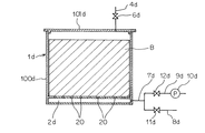
未炭酸化Ca含有原料の予成形体を実質的に気密な容器内に収納した後、該容器内を減圧する脱気工程と、
該脱気工程に引き続き、前記容器内に炭酸ガスを供給して予成形体の未炭酸化Ca含有原料に炭酸化反応を生じさせる炭酸化工程とを有することを特徴とする炭酸固化体の製造方法。
[10]上記[9]の製造方法において、未炭酸化Ca含有原料の予成形体に水を含ませた後、脱気工程を行い、予成形体内部の減圧により前記水の一部を排出することを特徴とする炭酸固化体の製造方法。
[8] After water is contained in the carbonated solid obtained by the production method of any one of [1] to [6] above, a part of the water is obtained by reducing the pressure inside the carbonated solid. Is discharged, and then the carbonized solid body is again subjected to a carbonation reaction in the presence of carbon dioxide gas.
[9] A method for producing a carbonated solid body by bringing a powdery uncarbonated Ca-containing raw material into contact with carbon dioxide gas in a moisture-containing state and solidifying by a carbonation reaction,
A degassing step of depressurizing the inside of the container after storing the preformed uncarbonated Ca-containing raw material in a substantially airtight container;
Subsequent to the degassing step, a carbonized solidified body is produced, comprising: a carbonation step of supplying carbon dioxide gas into the container to cause a carbonation reaction on the uncarbonated Ca-containing raw material of the preform. Method.
[10] In the production method of [9] above, after adding water to the preformed body of the uncarbonated Ca-containing raw material, a degassing step is performed, and a part of the water is discharged by decompression inside the preformed body. A method for producing a carbonate solidified product, characterized by comprising:
[11]上記[9]又は[10]の製造方法において、炭酸化工程が、
容器内に炭酸ガスの供給を行って予成形体の未炭酸化Ca含有原料に炭酸化反応を生じさせる初期炭酸化工程と、
該初期炭酸化工程に引き続き、容器内に供給する炭酸ガス量を減少させるか又は容器内への炭酸ガスの供給を休止する中間処理工程と、
該中間処理工程に引き続き、容器内に供給する炭酸ガス量を増加させるか又は容器内への炭酸ガスの供給を再開し、前記予成形体の未炭酸化Ca含有原料に炭酸化反応を生じさせる後期炭酸化工程とを有することを特徴とする炭酸固化体の製造方法。
[12]上記[11]の製造方法において、中間処理工程では、容器内への炭酸ガスの供給を休止するとともに、容器内雰囲気を空気以下の炭酸ガス濃度とすることを炭酸固化体の製造方法。
[13]上記[9]〜[12]のいずれかの製造方法で得られ、且つ水分を含んだ炭酸固化体の内部を減圧し、しかる後、該炭酸固化体に炭酸ガス存在下で再度炭酸化反応を生じさせることを特徴とする炭酸固化体の製造方法。
[14]上記[9]〜[10]のいずれかの製造方法で得られた炭酸固化体の内部に水を含ませた後、該炭酸固化体の内部を減圧することにより前記水の一部を排出し、しかる後、前記炭酸固化体に炭酸ガス存在下で再度炭酸化反応を生じさせることを特徴とする炭酸固化体の製造方法。
なお、本発明における上記炭酸ガスには、炭酸ガス含有ガスの一部として含有されるものも含まれる。
[11] In the production method of [9] or [10] above, the carbonation step includes
An initial carbonation step in which carbon dioxide gas is supplied into the container to cause a carbonation reaction in the uncarbonated Ca-containing raw material of the preform,
Subsequent to the initial carbonation step, an intermediate treatment step of reducing the amount of carbon dioxide supplied into the container or stopping the supply of carbon dioxide into the container;
Subsequent to the intermediate treatment step, the amount of carbon dioxide supplied into the container is increased or the supply of carbon dioxide into the container is restarted to cause a carbonation reaction on the uncarbonated Ca-containing raw material of the preform. A method for producing a solidified carbonic acid product, comprising a later carbonation step.
[12] In the production method of [11] above, in the intermediate treatment step, the carbon dioxide gas supply to the container is stopped and the atmosphere in the container is set to a carbon dioxide gas concentration equal to or lower than that of air. .
[13] The inside of the carbonated solid obtained by the production method according to any one of the above [9] to [12] is decompressed, and then the carbonated solid is again carbonated in the presence of carbon dioxide gas. A method for producing a solidified carbonic acid product, characterized by causing a solidification reaction.
[14] After water is contained in the carbonated solid obtained by the production method of any one of [9] to [10] above, a part of the water is obtained by reducing the pressure inside the carbonated solid. Is discharged, and then the carbonized solid body is again subjected to a carbonation reaction in the presence of carbon dioxide gas.
In addition, what is contained as a part of carbon dioxide containing gas is also contained in the said carbon dioxide in this invention.
上記[1]〜[8]の発明によれば、炭酸ガスの供給によって原料に炭酸化反応を生じさせる製造工程の途中において、炭酸カルシウムの析出が減少ないしは停止した段階で、原料に供給する炭酸ガス量を減少させるか若しくは炭酸ガスの供給を休止することにより表面付着水への炭酸ガスの溶解を抑制し、この中間工程によって再び炭酸カルシウムの析出反応が効率的に生じるような状態になった段階で、原料に対する定常的な炭酸ガスの供給を再開することにより、原料を効率的に炭酸固化させることができ、良好な品質の炭酸固化体を従来に較べて短い時間で効率的に製造することができる。さらに、上記[4]、[5]、[7]、[8]の発明によれば、炭酸ガスと原料中の未炭酸化Caとを水を介してより効率的に反応させることができ、より良好な品質の炭酸固化体を効率的に製造することができる。
また、上記[9]〜[14]の発明によれば、事前の減圧により予成形体内への炭酸ガスの浸透を効率的に行わせることができるため、良好な品質の炭酸固化体を従来に較べて短い時間で効率的に製造することができる。さらに、上記[10]、[13]、」[14]の発明によれば、炭酸ガスと原料中の未炭酸化Caとを水を介してより効率的に反応させることができ、より良好な品質の炭酸固化体を効率的に製造することができる。
According to the above inventions [1] to [8], the carbonic acid supplied to the raw material when the precipitation of calcium carbonate is reduced or stopped in the course of the production process in which the carbonic acid is supplied to cause a carbonation reaction to the raw material. By reducing the amount of gas or stopping the supply of carbon dioxide, the dissolution of carbon dioxide in the water adhering to the surface was suppressed, and this intermediate process resulted in a state in which the calcium carbonate precipitation reaction occurred efficiently again. By restarting the steady supply of carbon dioxide gas to the raw material at the stage, the raw material can be efficiently carbonated, and a carbonated product of good quality can be efficiently produced in a shorter time than before. be able to. Furthermore, according to the invention of the above [4], [5], [7], [8], carbon dioxide gas and uncarbonated Ca in the raw material can be reacted more efficiently through water, Better quality carbonated solids can be produced efficiently.
In addition, according to the above inventions [9] to [14], carbon dioxide gas can be efficiently permeated into the preformed body by pre-depressurization. It can be manufactured efficiently in a shorter time. Furthermore, according to the inventions of [10], [13], and [14] above, carbon dioxide gas and uncarbonated Ca in the raw material can be reacted more efficiently through water, which is better. It is possible to efficiently produce a quality carbonated solid.
まず、本願の第1の製造方法について説明する。
この方法は、粉粒状の未炭酸化Ca含有原料を、水分を含んだ状態で炭酸ガスと接触させて炭酸化反応で固結させることにより、炭酸固化体を製造する方法であって、未炭酸化Ca含有原料に炭酸ガスの供給を行って、この未炭酸化Ca含有原料に炭酸化反応を生じさせる初期炭酸化工程(A)と、この初期炭酸化工程(A)に引き続き、未炭酸化Ca含有原料に供給する炭酸ガス量を減少させるか又は未炭酸化Ca含有原料への炭酸ガスの供給を休止する中間処理工程(B)と、この中間処理工程(B)に引き続き、未炭酸化Ca含有原料に供給する炭酸ガス量を増加させるか又は未炭酸化Ca含有原料への炭酸ガスの供給を再開し、未炭酸化Ca含有原料に炭酸化反応を生じさせる後期炭酸化工程(C)とを有する。
First, the 1st manufacturing method of this application is demonstrated.
This method is a method for producing a solidified carbonate by bringing a powdered uncarbonated Ca-containing raw material into contact with carbon dioxide gas in a moisture-containing state and solidifying it by a carbonation reaction. An initial carbonation step (A) in which carbon dioxide gas is supplied to the raw material containing carbonized carbon to cause a carbonation reaction in the raw material containing uncarbonated Ca, and subsequent to this initial carbonation step (A), non-carbonation An intermediate treatment step (B) in which the amount of carbon dioxide supplied to the Ca-containing raw material is reduced or the supply of carbon dioxide gas to the non-carbonated Ca-containing raw material is suspended, and this intermediate treatment step (B) is followed by non-carbonation. Late carbonation step (C) in which the amount of carbon dioxide gas supplied to the Ca-containing raw material is increased or the supply of carbon dioxide gas to the non-carbonated Ca-containing raw material is restarted to cause a carbonation reaction in the non-carbonated Ca-containing raw material And have.
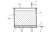
図1は本願の第1の製造方法の一実施形態を示すもので、未炭酸化Ca含有原料を型枠1に充填して原料充填層Aを形成し、この原料充填層A内に炭酸ガスを吹き込むようにしたものである。図1は、原料充填層Aを形成する型枠1を縦断面した状態を示している。
前記型枠1は実質的に気密又は半気密にすることが可能な型枠であって、本実施形態では、容器状の本体100とその上部を閉塞する蓋体101とから構成されている。前記本体100の底部にはガス給気部2(ガス給気用空間)が設けられるとともに、このガス給気部2と本体100との間の隔壁には多数のガス通孔20が形成されている。前記ガス給気部2にはガス供給管3が接続され、このガス供給管3を通じてガス給気部2内に炭酸ガス又は炭酸ガス含有ガス(以下、総称して“炭酸ガス”という)が供給される。また、型枠1の上部には型枠内に供給されたガスの排気を行うための排気管4が接続されている。その他図面において、5,6は各配管系に設けられた開閉弁である。
FIG. 1 shows an embodiment of the first production method of the present application. An uncarbonated Ca-containing raw material is filled in a
The
型枠1内にはスラグなどの粉粒状の未炭酸化Ca含有原料が装入され、原料充填層Aが形成される。未炭酸化Ca含有原料が炭酸ガスと接触して炭酸化反応により固結するには、先に述べたように水分(原料粒子の表面付着水)が必要であり、このため未炭酸化Ca含有原料は適度な水分を含有している必要がある。このため必要に応じて未炭酸化Ca含有原料に水分を添加する。この水分添加は型枠1に装入する前に行ってもよいし、装入後に行ってもよい。また、型枠装入後に行う場合には、型枠1の上部を開放した状態で、型枠1ごと水槽内の水に浸漬してもよいし、原材料充填層Aの上部から十分な量の水を散水してもよい。通常、原料充填層の含水率は3〜12%、好ましくは5〜9%程度とするのが適当である。
上記のように水分を含んだ原料充填層Aを形成した後、型枠1内に吹き込まれる炭酸ガスが原料充填層全体に良く浸透するようにするため型枠に蓋体101を装着し、型枠1を気密又は半気密状態にする。
以上のようにして原料充填層Aを形成した後、以下に述べるような工程(A)〜(C)を順に行い、炭酸固化体を製造する。
In the
After forming the raw material filled layer A containing moisture as described above, the
After forming the raw material packed layer A as described above, steps (A) to (C) as described below are sequentially performed to produce a solidified carbonate.
・初期炭酸化工程(A)
この工程では、未炭酸化Ca含有原料に所定時間(原料充填層の規模やガス流速などによって異なるが、一般的には8〜24時間程度)炭酸ガスの供給を行って、未炭酸化Ca含有原料に炭酸化反応を生じさせる。この工程は未炭酸化Ca含有原料の炭酸化を目的としたものであるため、定常的な炭酸ガスの供給を行うが、後述する後期炭酸化工程(C)に較べて原料からCaイオンが溶出しやすく、顕著な発熱を伴う活発な炭酸化反応が生じる。図1の実施形態では、ガス供給管3を通じて供給された炭酸ガスはガス給気部2に導入された後、ガス通孔20から上方の原料充填層A内に吹き込まれる。原料充填層A内を通過する炭酸ガスの一部は、原料粒子からその表面付着水に溶出したCaイオンと反応し、原料粒子の表面にCaCO3が析出し、これがバインダーとなって原料充填層Aの固結が進行する。炭酸ガスの残りは原料充填層Aを通過して排気管4から型枠1外に排出される。また、場合によっては、排気管4の開閉弁6を閉じた状態で原料充填層A内に炭酸ガスを供給するようにしてもよいが、その場合には、時々開閉弁6を開にして型枠1内に溜まったガスを放出し、型枠1内の炭酸ガス濃度が所定レベル以上に維持されるようにすることが好ましい。
・ Initial carbonation process (A)
In this step, carbon dioxide gas is supplied to the uncarbonated Ca-containing raw material for a predetermined time (generally depending on the scale of the raw material packed bed, gas flow rate, etc., but generally about 8 to 24 hours). A carbonation reaction is caused in the raw material. This process is intended for the carbonation of uncarbonated Ca-containing raw materials, so a steady supply of carbon dioxide gas is carried out, but Ca ions are eluted from the raw materials compared to the later carbonation process (C) described later. Active carbonation reaction with significant exotherm occurs. In the embodiment of FIG. 1, the carbon dioxide gas supplied through the
・中間処理工程(B)
以上のような炭酸化処理(初期炭酸化工程)を所定時間続けると、原料粒子からのCaイオンの溶解速度自体が遅くなること、原料粒子表面にCaCO3の膜が形成され、これがCaイオンの溶出を妨げるようになること、などの要因によってCaイオンの表面付着水中への溶出が遅くなる。一方において、原料に対して炭酸ガスは供給され続けるため、表面付着水中の炭酸ガス濃度(CO2分圧)が増加してpHが低下し、重炭酸カルシウムの飽和状態となるため、炭酸カルシウムの析出反応が停止ないしは大幅に減少する。
このため、適当な段階で未炭酸化Ca含有原料に供給する炭酸ガス量を減少させるか又は未炭酸化Ca含有原料への炭酸ガスの供給を休止する(中間処理工程)。この工程では、例えば以下のような方法を採ることができる。
・ Intermediate treatment process (B)
When the carbonation treatment (initial carbonation step) as described above is continued for a predetermined time, the dissolution rate of Ca ions from the raw material particles itself decreases, and a CaCO 3 film is formed on the surface of the raw material particles. Due to factors such as hindering elution, the elution of Ca ions into the surface-attached water is delayed. On the other hand, since carbon dioxide continues to be supplied to the raw material, the concentration of carbon dioxide in the surface-attached water (CO 2 partial pressure) increases and the pH decreases, resulting in a saturated state of calcium bicarbonate. The precipitation reaction is stopped or significantly reduced.
For this reason, the amount of carbon dioxide supplied to the uncarbonated Ca-containing material is reduced at an appropriate stage, or the supply of carbon dioxide to the uncarbonated Ca-containing material is suspended (intermediate treatment step). In this step, for example, the following method can be employed.
(1)ガス供給管3を通じた炭酸ガスの供給を休止するか若しくはガス供給量を大幅に減少させる。
(2)ガス供給管3を通じた炭酸ガスの供給を休止した後、ガス供給管3を通じて型枠1内に空気を供給し、未炭酸化Ca含有原料内部の雰囲気を空気と置換する。
(3)ガス供給管3を通じた炭酸ガスの供給を休止した後、ガス供給管3を通じて型枠1内に空気未満の炭酸ガス濃度のガス(例えば、窒素ガス)を供給し、未炭酸化Ca含有原料内部の雰囲気を当該ガスと置換する。
(4)ガス供給管3を通じた炭酸ガスの供給を休止した後、 ガス供給管3を吸引ポンプ(図示せず)に接続し、この吸引ポンプによる吸引で未炭酸化Ca含有原料内部を減圧することにより、未炭酸化Ca含有原料内部の雰囲気を空気未満の炭酸ガス濃度とする。
これら(1)〜(4)の方法は任意に選択できるが、未炭酸化Ca含有原料内部の炭酸ガス濃度を短時間で且つ十分に低減させたい場合には、(2)〜(4)のいずれかの方法、好ましくは(3)又は(4)の方法、特に好ましくは(4)の方法が望ましい。(4)の方法では、減圧による脱気によって原料粒子の表面付着水中の炭酸ガス濃度を短時間に低減させることができる。
(1) Stop the supply of carbon dioxide gas through the
(2) After stopping the supply of carbon dioxide gas through the
(3) After stopping the supply of carbon dioxide gas through the
(4) After stopping the supply of carbon dioxide gas through the
These methods (1) to (4) can be arbitrarily selected. However, when it is desired to sufficiently reduce the carbon dioxide concentration inside the uncarbonated Ca-containing raw material in a short time, (2) to (4) Any method, preferably the method (3) or (4), particularly preferably the method (4) is desirable. In the method (4), the concentration of carbon dioxide in the water adhering to the surface of the raw material particles can be reduced in a short time by degassing under reduced pressure.
以上の操作を行うことにより、原料粒子の表面付着水への炭酸ガスの溶解が実質的に停止するとともに、(a)原料充填層A中のCO2分圧の低下→(b)表面付着水中の炭酸ガスの脱気→(c)表面付着水のpH上昇→(d)炭酸カルシウムの析出→(e)表面付着水中のCaイオン濃度の低下→(f)原料粒子から表面付着水中へのCaイオンの溶出速度上昇、という機構によって、再び炭酸カルシウムの析出反応が効率的に生じるような状態となる。
この中間処理工程(B)を行う時間等は特に限定されないが、原料充填層A中のCO2分圧を十分に低下させることが好ましいことから、例えば、原料充填層内部の雰囲気を空気や他のガス(例えば、窒素ガス)で置換する場合には、原料充填層の体積の5倍以上、好ましくは10倍以上の量(トータル量)の空気やガスが原料充填層中に供給される程度の時間を目安とする。
By performing the above operations, the dissolution of carbon dioxide gas in the surface adhering water of the raw material particles is substantially stopped, and (a) the CO 2 partial pressure in the raw material packed bed A is reduced → (b) the surface adhering water Degassing of carbon dioxide gas → (c) Increasing pH of surface adhering water → (d) Precipitation of calcium carbonate → (e) Decreasing Ca ion concentration in surface adhering water → (f) Ca from raw material particles to surface adhering water Due to the mechanism of increasing the elution rate of ions, a state in which the precipitation reaction of calcium carbonate occurs efficiently again is obtained.
Although the time for performing this intermediate treatment step (B) is not particularly limited, it is preferable to sufficiently reduce the CO 2 partial pressure in the raw material packed bed A. In the case of replacing with a gas (for example, nitrogen gas), the amount of air or gas that is 5 times or more, preferably 10 times or more the volume of the raw material packed bed (total amount) is supplied into the raw material packed bed. As a guide.
・後期炭酸化工程(C)
上記のような中間処理工程(B)を所定時間行うことによって、上述した(a)〜(f)の機構により炭酸カルシウムの析出反応が再び活性化された段階で、未炭酸化Ca含有原料に対する定常的な炭酸ガスの供給を再開する。すなわち、例えば上記(1)〜(4)の操作を行っている場合にはこれを終了し、初期炭酸化工程(A)と同様に、ガス供給管3を通じた未炭酸化Ca含有原料内への炭酸ガスの供給を行う。
この後期炭酸化工程(C)は原料充填層Aが十分に固結するまで行われるもので、その実施時間は特に限定されないが、例えば、炭酸ガス供給速度を初期炭酸化工程(A)と同じにした場合、同工程(A)の1/30〜1/3程度の時間が目安となる。現象的には、炭酸カルシウムの析出によって表面付着水中のCaイオン濃度が低下する一方で、表面付着水中への炭酸ガスの溶解が続くと、表面付着水のpHが低下し、表面付着水はpH8以下のCa(HCO3)2の溶液となるので、炭酸カルシウムの析出が生じにくくなる。したがって、このように表面付着水がpH8以下になる時点が後期炭酸化工程(C)の終了の目安となる。後期炭酸化工程(C)終了後、固結した原料充填層Aを脱型し、製品である炭酸固化体を取り出す。
なお、上記中間処理工程(B)と後期炭酸化工程(C)は、これを2回以上繰り返して行うこともできる。例えば、原料充填層Aの大きさや原料粒度によって炭酸化処理の効率には差があり、上記中間処理工程(B)と後期炭酸化工程(C)を2回以上行った方が、処理効率面で有利な場合もあるからである。
・ Late carbonation process (C)
By performing the intermediate treatment step (B) as described above for a predetermined time, the calcium carbonate precipitation reaction is activated again by the above-described mechanisms (a) to (f), and the uncarbonated Ca-containing raw material is thus treated. Resume steady carbon dioxide supply. That is, for example, when the operations (1) to (4) are performed, the operation is terminated, and into the uncarbonated Ca-containing raw material through the
This late carbonation step (C) is performed until the raw material packed bed A is sufficiently solidified, and its implementation time is not particularly limited. For example, the carbon dioxide supply rate is the same as that of the initial carbonation step (A). In this case, a time of about 1/30 to 1/3 of the step (A) is a guide. Phenomenologically, the Ca ion concentration in the surface-attached water decreases due to the precipitation of calcium carbonate, but if the carbon dioxide gas continues to dissolve in the surface-attached water, the pH of the surface-attached water decreases, and the surface-attached water has a pH of 8 Since it becomes the following Ca (HCO 3 ) 2 solution, precipitation of calcium carbonate hardly occurs. Therefore, the point at which the surface adhering water becomes
The intermediate treatment step (B) and the late carbonation step (C) can be repeated twice or more. For example, there is a difference in the efficiency of the carbonation treatment depending on the size of the raw material packed bed A and the raw material particle size, and it is better to perform the intermediate treatment step (B) and the late carbonation step (C) twice or more in terms of treatment efficiency. This is because it may be advantageous.
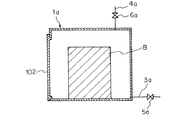
図1に示した実施形態は型枠1内に原料充填層Aを形成し、この原料充填層内に炭酸ガスを吹き込むようにしたものであるが、本願の第1の製造方法は、未炭酸化Ca含有原料を炭酸ガス雰囲気内に置き、炭酸ガスを原料内部に浸透させるような実施形態を採ることもできる。この場合には、未炭酸化Ca含有原料を圧縮成形などによって予成形し、この予成形されたものを炭酸ガス雰囲気内に置いて炭酸固化させる。
図2は、その一実施形態を示すもので、処理容器を縦断面した状態で示している。
処理容器1aは実質的に気密にすることが可能な容器であって、その側部には原料出し入れ部102が設けられている。この処理容器1aにはガス供給管3aが接続され、このガス供給管3を通じて処理容器1a内に炭酸ガスが供給される。また、処理容器1aの上部には処理容器内に供給されたガスの排気を行うための排気管4aが接続されている。その他図面において、5a,6aは各配管系に設けられた開閉弁である。
In the embodiment shown in FIG. 1, a raw material filling layer A is formed in a
FIG. 2 shows the embodiment, and shows the processing container in a longitudinal section.
The processing container 1a is a container that can be substantially airtight, and a raw material taking-in / out
粉粒状の未炭酸化Ca含有原料には、先に述べたような理由から予め所定の水分が添加されるとともに、圧縮成形などの方法により任意の形状に予成形される。なお、未炭酸化Ca含有原料を予成形するに当たっては、予成形体内の貫通気孔が過剰に塞がれないことを限度として、セメントなどのポゾラン反応物質、糖蜜、デンプン、リグニン、パルプ廃液などのバインダーを未炭酸化Ca含有原料に配合してもよい。未炭酸化Ca含有原料の予成形体Bは、処理容器1a内に装入(収納)され、処理容器1a内は気密にされる。そして、この状態で先に述べたような工程(A)〜(C)を順に行い、炭酸固化体を製造する。
すなわち、初期炭酸化工程(A)では、ガス供給管3aを通じて処理容器1a内に所定時間、未炭酸化Ca含有原料の炭酸化を目的として定常的な炭酸ガスの供給を行う。供給された炭酸ガスの一部は予成形体Bの表面から内部に浸透し、未炭酸化Ca含有原料に炭酸化反応を生じさせる。炭酸ガスの残りは排気管4aから処理容器1a外に排出される。また、場合によっては、図1の実施形態と同様に、排気管4aの開閉弁6aを閉じた状態で処理容器1a内に炭酸ガスを供給するようにしてもよい。
The powdery uncarbonated Ca-containing raw material is preliminarily molded into an arbitrary shape by a method such as compression molding, in addition to predetermined moisture added in advance for the reasons described above. In addition, when pre-molding raw materials containing uncarbonated Ca, pozzolanic reactants such as cement, molasses, starch, lignin, pulp waste liquid, etc., as long as the through-holes in the preform are not blocked excessively You may mix | blend a binder with an uncarbonated Ca containing raw material. The preform B of the uncarbonated Ca-containing raw material is charged (stored) in the processing container 1a, and the processing container 1a is hermetically sealed. Then, the steps (A) to (C) as described above are sequentially performed in this state to produce a solidified carbonate.
That is, in the initial carbonation step (A), a steady carbon dioxide gas is supplied through the gas supply pipe 3a into the processing vessel 1a for a predetermined time for the purpose of carbonation of the uncarbonated Ca-containing material. Part of the supplied carbon dioxide gas penetrates from the surface of the preform B to the inside, causing a carbonation reaction to occur in the uncarbonated Ca-containing raw material. The remainder of the carbon dioxide gas is discharged out of the processing container 1a from the
以上のような炭酸化処理(初期炭酸化工程)を所定時間続けた後、適当な段階、すなわち、原料粒子の表面付着水中の炭酸ガス濃度が増加してpHが低下し、重炭酸カルシウムの飽和状態となった段階で中間処理工程(B)に移行し、処理容器1a内に供給する炭酸ガス量を減少させるか又は処理容器1a内への炭酸ガスの供給を休止する。この結果、予成形体B内部に供給(浸透)される炭酸ガス量が減少するか又は炭酸ガスの供給(浸透)が休止される。この場合、図1の実施形態と同様に、例えば以下のような方法を採ることができる。
(1)ガス供給管3aを通じた炭酸ガスの供給を休止するか若しくはガス供給量を大幅に減少させる。
(2)ガス供給管3aを通じた炭酸ガスの供給を休止した後、ガス供給管3aを通じて処理容器1a内に空気を供給し、処理容器1a内の雰囲気を空気と置換する。
(3)ガス供給管3aを通じた炭酸ガスの供給を休止した後、ガス供給管3aを通じて処理容器1a内に空気未満の炭酸ガス濃度のガス(例えば、窒素ガス)を供給し、処理容器1a内の雰囲気を当該ガスと置換する。
(4)ガス供給管3aを通じた炭酸ガスの供給を休止した後、ガス供給管3aを吸引ポンプ(図示せず)に接続し、この吸引ポンプによる吸引で処理容器1a内を減圧することにより、処理容器1a(及び予成形体B)内の雰囲気を空気未満の炭酸ガス濃度とする。
After the carbonation treatment (initial carbonation step) as described above is continued for a predetermined time, the carbon dioxide gas concentration in the surface adhering water of the raw material particles increases and the pH decreases, so that the calcium bicarbonate is saturated. When the state is reached, the process proceeds to the intermediate processing step (B), and the amount of carbon dioxide supplied into the processing container 1a is reduced or the supply of carbon dioxide into the processing container 1a is stopped. As a result, the amount of carbon dioxide supplied (penetrated) into the preform B decreases or the supply (penetration) of carbon dioxide is suspended. In this case, for example, the following method can be adopted as in the embodiment of FIG.
(1) Stop the supply of carbon dioxide gas through the gas supply pipe 3a or greatly reduce the gas supply amount.
(2) After stopping the supply of carbon dioxide gas through the gas supply pipe 3a, air is supplied into the processing container 1a through the gas supply pipe 3a, and the atmosphere in the processing container 1a is replaced with air.
(3) After stopping the supply of carbon dioxide gas through the gas supply pipe 3a, a gas (for example, nitrogen gas) having a carbon dioxide concentration less than air is supplied into the processing container 1a through the gas supply pipe 3a, and the inside of the processing container 1a The atmosphere is replaced with the gas.
(4) After stopping the supply of carbon dioxide gas through the gas supply pipe 3a, the gas supply pipe 3a is connected to a suction pump (not shown), and the inside of the processing container 1a is decompressed by suction by the suction pump, The atmosphere in the processing container 1a (and the preform B) is set to a carbon dioxide gas concentration less than air.
これら(1)〜(4)の方法は任意に選択できるが、処理容器1a(及び予成形体B)内の炭酸ガス濃度を短時間で且つ十分に低減させたい場合には、(2)〜(4)のいずれかの方法、好ましくは(3)又は(4)の方法、特に好ましくは(4)の方法が望ましい。(4)の方法では、減圧による脱気によって原料粒子の表面付着水中の炭酸ガス濃度を短時間に低減させることができる。
以上の操作を行うことにより、原料粒子の表面付着水への炭酸ガスの溶解が実質的に停止するとともに、上述した(a)〜(f)の機構によって炭酸カルシウムの析出反応が再び活性化される。
These methods (1) to (4) can be arbitrarily selected. However, when it is desired to sufficiently reduce the carbon dioxide concentration in the processing container 1a (and the preform B) in a short time, (2) to (2) to The method (4), preferably the method (3) or (4), particularly preferably the method (4) is desirable. In the method (4), the concentration of carbon dioxide in the water adhering to the surface of the raw material particles can be reduced in a short time by degassing under reduced pressure.
By performing the above operation, the dissolution of carbon dioxide gas in the water adhering to the surface of the raw material particles is substantially stopped, and the precipitation reaction of calcium carbonate is reactivated by the mechanisms (a) to (f) described above. The
上記のような中間処理工程(B)を適当な時間行うことによって炭酸カルシウムの析出反応が活性化された段階で、後期炭酸化工程(C)に移行し、処理容器1aに対する定常的な炭酸ガスの供給を再開する。すなわち、例えば、上記(1)〜(4)の操作を行っている場合はこれを終了し、初期炭酸化工程(A)と同様に、ガス供給管3aを通じた処理容器1a内への炭酸ガスの供給を行う。
この後期炭酸化工程(C)は予成形体Bが十分に固結するまで行われ、後期炭酸化工程(C)終了後、製品である固結した予成形体B(炭酸固化体)を処理容器1aから取り出す。
この場合も、上記中間処理工程(B)と後期炭酸化工程(C)は、これを2回以上繰り返して行うことができる。なお、各工程(A)〜(C)を行う各時間は、図1で述べた実施形態と同様である。
なお、以上述べた本願の第1の製造方法の一連の工程において、各工程での処理時間に特別な制限はない。したがって、例えば、初期炭酸化工程(A)に引き続き中間処理工程(B)と後期炭酸化工程(C)を2回以上繰り返して行う場合において、初期炭酸化工程(A)の処理時間と2回以上行われる各後期炭酸化工程(C)の処理時間とが同程度の長さであっても構わない。
At the stage where the precipitation reaction of calcium carbonate is activated by performing the intermediate treatment step (B) as described above for an appropriate time, the process proceeds to the late carbonation step (C), and steady carbon dioxide gas for the treatment vessel 1a. Restart the supply. That is, for example, when the operations (1) to (4) are performed, the operation is terminated, and the carbon dioxide gas into the processing container 1a through the gas supply pipe 3a is the same as in the initial carbonation step (A). Supply.
This late carbonation step (C) is performed until the preform B is sufficiently solidified, and after completion of the late carbonation step (C), the solidified preform B (carbonate solidified product) is processed. Remove from container 1a.
Also in this case, the intermediate treatment step (B) and the late carbonation step (C) can be repeated twice or more. In addition, each time which performs each process (A)-(C) is the same as that of embodiment described in FIG.
In the series of steps of the first manufacturing method of the present application described above, there is no particular limitation on the processing time in each step. Therefore, for example, when the intermediate carbonation step (B) and the late carbonation step (C) are repeated twice or more subsequent to the initial carbonation step (A), the initial carbonation step (A) is performed twice as long as the treatment time. The processing time of each late carbonation process (C) performed above may be comparable length.
また、以上述べた本願の第1の製造方法の一連の工程完了後に、炭酸固化体の強度をさらに高めるため、再炭酸化工程を付加してもよい。この再炭酸化工程では、水分を含んだ炭酸固化体に炭酸ガス存在下で再度炭酸化反応を生じさせる。スラグなどの粉粒状の未炭酸化Ca含有原料の充填層を炭酸化反応により固結させた炭酸固化体は全体に微細な貫通気孔を有しており、その内部に水を含ませる(浸透させる)ことができる。また、再炭酸化される炭酸固化体は、既に炭酸化反応によって生成したCaCO3によって固結しているが、未炭酸化Ca含有原料中には未だ炭酸化していないCaが相当量含まれており、また、各原料粒子の全表面が析出したCaCO3で覆われている訳ではないので、上記再炭酸化の際にも原料粒子から表面付着水にCaイオンが溶出し、炭酸化反応が進行することになる。 In addition, after completion of the series of steps of the first production method of the present application described above, a recarbonation step may be added in order to further increase the strength of the carbonate solidified body. In this recarbonation step, a carbonation reaction is caused again in the presence of carbon dioxide in the carbonated solid body containing water. The carbonated solidified body obtained by consolidating a packed bed of granular uncarbonated Ca-containing raw material such as slag by a carbonation reaction has fine through-holes as a whole, and contains water (permeates it). )be able to. The carbonated solid to be recarbonated is already consolidated by CaCO 3 produced by the carbonation reaction, but the uncarbonated Ca-containing raw material contains a considerable amount of Ca that has not yet been carbonated. In addition, since the entire surface of each raw material particle is not covered with the precipitated CaCO 3 , Ca ions are eluted from the raw material particles into the surface adhering water during the re-carbonation, and the carbonation reaction is caused. Will progress.
また、この再炭酸化工程では、先に述べた本願の第1の製造方法の一連の工程を利用することができる。すなわち、この場合には、炭酸固化体が入れられた適当な容器内に炭酸ガスの供給を行って炭酸固化体に炭酸化反応を生じさせる初期炭酸化工程(A1)と、この初期炭酸化工程(A1)に引き続き、容器内に供給する炭酸ガス量を減少させるか又は容器内への炭酸ガスの供給を休止する中間処理工程(B1)と、この中間処理工程(B1)に引き続き、容器内に供給する炭酸ガス量を増加させるか又は容器内への炭酸ガスの供給を再開し、前記炭酸固化体に炭酸化反応を生じさせる後期炭酸化工程(C1)とを有するものである。 Moreover, in this recarbonation process, a series of processes of the first manufacturing method of the present application described above can be used. That is, in this case, an initial carbonation step (A1) in which carbonic acid gas is supplied into a suitable container containing the carbonized solidified body to cause a carbonation reaction in the carbonized solidified body, and this initial carbonation step. Subsequent to (A1), the intermediate processing step (B1) in which the amount of carbon dioxide gas supplied into the container is reduced or the carbon dioxide gas supply to the container is stopped, and the intermediate processing step (B1), The carbon dioxide gas supplied to the container is increased, or the supply of carbon dioxide gas into the container is restarted to have a late carbonation step (C1) in which a carbonation reaction is caused in the carbonate solidified product.
このような実施形態では、初期炭酸化工程(A1)を所定時間続けた後、適当な段階、すなわち、原料粒子の表面付着水中の炭酸ガス濃度が増加してpHが低下し、重炭酸カルシウムの飽和状態となった段階で中間処理工程(B1)に移行し、容器内に供給する炭酸ガス量を減少させるか又は容器内への炭酸ガスの供給を休止する。この場合、例えば、図1,図2の実施形態で述べた(1)〜(4)の方法を採ることができ、その詳細は先に述べたとおりである。
以上の操作を行うことにより、原料粒子の表面付着水への炭酸ガスの溶解が実質的に停止するとともに、先に述べた(a)〜(f)の機構によって炭酸カルシウムの析出が活性化する。
上記のような中間処理工程(B1)を適当な時間行うことによって炭酸カルシウムの析出反応が再び活性化された段階で、後期炭酸化工程(C1)に移行し、容器に対する定常的な炭酸ガスの供給を再開する。
この場合も、上記中間処理工程(B1)と後期炭酸化工程(C1)は、これを2回以上繰り返して行うことができる。
In such an embodiment, after the initial carbonation step (A1) is continued for a predetermined time, the carbon dioxide gas concentration in the water adhering to the surface of the raw material particles is increased and the pH is lowered. When the saturation state is reached, the process proceeds to the intermediate treatment step (B1), and the amount of carbon dioxide supplied into the container is reduced or the supply of carbon dioxide into the container is stopped. In this case, for example, the methods (1) to (4) described in the embodiments of FIGS. 1 and 2 can be adopted, and the details thereof are as described above.
By performing the above operation, the dissolution of carbon dioxide gas in the water adhering to the surface of the raw material particles is substantially stopped, and the precipitation of calcium carbonate is activated by the mechanisms (a) to (f) described above. .
At the stage where the precipitation reaction of calcium carbonate is activated again by performing the intermediate treatment step (B1) as described above for an appropriate time, the process shifts to the late carbonation step (C1), and the steady carbon dioxide gas is supplied to the container. Restart supply.
Also in this case, the intermediate treatment step (B1) and the late carbonation step (C1) can be repeated twice or more.
次に、以上述べた本願の第1の製造方法のより好ましい実施形態について説明する。この実施形態には、上述した第1の製造方法の一連の工程に対して、(a)初期炭酸化工程前に減圧工程を付加する形態、(b)一連の工程完了後に、減圧工程及びこれに続く炭酸化工程を含む再炭酸化工程を付加する形態、(c)以上の(a),(b)で行う両工程を付加する形態、がある。
先に述べたように、スラグなどの粉粒状の未炭酸化Ca含有原料を炭酸化反応により固結させて炭酸固化体を製造する際の原料中の未炭酸化CaとCO2との反応は、原料粒子の表面に存在する水(表面付着水)に原料粒子間を流れるCO2が溶解するとともに、原料粒子側からはCaイオンが溶出し、この水に溶解・溶出したCO2とCaイオンとが反応(炭酸化反応)することにより、原料粒子表面にCaCO3が析出するものであると考えられる。
Next, a more preferred embodiment of the first manufacturing method of the present application described above will be described. In this embodiment, (a) a mode in which a pressure reduction step is added before the initial carbonation step, and (b) a pressure reduction step after completion of the series of steps and the series of steps of the first manufacturing method described above. There is a mode in which a re-carbonation step including a carbonation step following is added, and a mode in which both steps (c) and (a) and (b) are added.
As described above, the reaction between uncarbonated Ca and CO 2 in the raw material when a solidified carbonized raw material such as slag is solidified by a carbonation reaction to produce a carbonated solid is as follows. CO 2 flowing between the raw material particles dissolves in the water (surface adhering water) existing on the surface of the raw material particles, and Ca ions are eluted from the raw material particle side, and the dissolved CO 2 and Ca ions are dissolved and eluted in the water. It is considered that CaCO 3 precipitates on the surface of the raw material particles due to the reaction (carbonation reaction).
特許文献1などに示される従来技術では、未炭酸化Ca含有原料に適量の水分(例えば、含水率5〜10%程度)を添加した状態で炭酸化処理が行われているが、その際の水分添加の方法は、単純に未炭酸化Ca含有原料と水を混合するだけであるため、原料充填層内での水の分布状態が不均一となりやすい。この結果、水の多いところではCO2の通り路が十分に確保されないためCO2が十分に流れず、このため炭酸化反応が生じにくく、また、僅かに炭酸化反応が生じる場所もCaイオンが溶け込んだ水の表面部分(すなわち、原料粒子表面から離れた場所)であるため、生成するCaCO3は原料粒子どうしの結合に十分に寄与できないものと考えられる。一方、水が少ないところではCO2の通り路が十分に確保されるためCO2は流れるが、肝心の水分が少ないため、原料から溶出するCaイオンが少なく、この場合も炭酸化反応が生じにくくなるものと考えられる。したがって、水の分布状態が不均一であると、得られる炭酸固化体は炭酸化不足により強度不足を生じたり、強度のばらつきが大きいものとなってしまう。
In the prior art disclosed in
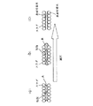
そこで、この本発明の好ましい形態では、原料充填層(炭酸固化体を再炭酸化させて強度向上を図る場合には“炭酸固化体”)内での水の分布状態を均一化するため、水分を含んだ原料充填層の内部を一旦減圧する処理を行い、しかる後、初期炭酸化工程(炭酸固化体を再炭酸化させて強度向上を図る場合には、再炭酸化工程)を行う。上記のような減圧処理を行うことにより、水の分布状態が均一化すると考えられる原理を、原料充填層の場合を例に図4(模式図)に基づいて説明する。
図4(a)は、適量の水(通常、炭酸化処理に必要且つ十分な量若しくはそれに近い量の水)を含んだ原料充填層(例えば、水を添加して混合した未炭酸化Ca含有原料を型枠に装入して構成された原料充填層)の内部を示している。この状態での原料粒子の間隙部分は、間隙の大きさや表面張力等の影響により水の存在状態にばらつきがあり、CO2の通り路を塞ぐように水が多量に存在する部分と、炭酸化反応に必要な量の水(原料粒子の表面付着水)が十分に存在していない部分とがある。そして、この状態で原料充填層内部を減圧すると、部分的に偏在していた水が引かれて移動し、表面付着水量が少なかった原料粒子の表面に付着する。この結果、原料粒子の間隙部分での水の存在状態が均一化され、図4(b)に示すように、各原料粒子に表面付着水が均一に存在し且つ原料粒子間にCO2の通り路となる間隙が適切に確保された状態が原料充填層全体に実現することになる。なお、上記減圧により原料充填層内に存在する水のうちの一部が充填層外に排出される場合もある。
Therefore, in this preferred embodiment of the present invention, in order to uniformize the water distribution state in the raw material packed bed (in the case of improving the strength by re-carbonizing the carbonate solidified body), Then, the inside of the raw material packed layer containing is temporarily depressurized, and then an initial carbonation step (recarbonation step in the case of increasing the strength by re-carbonizing the carbonized solid) is performed. Based on FIG. 4 (schematic diagram), the principle that the distribution state of water is considered to be uniform by performing the pressure reduction treatment as described above will be described with reference to FIG.
FIG. 4A shows a raw material packed layer (for example, containing uncarbonated Ca mixed with water added thereto) containing an appropriate amount of water (usually a sufficient amount of water necessary and close to the carbonation treatment). The inside of a raw material packed bed configured by charging raw materials into a mold is shown. The gap portion of the raw material particles in this state has a variation in the water existence state due to the influence of the size of the gap, surface tension, etc., and a portion where water is present so as to block the passage of CO 2 and carbonation There is a portion where the amount of water necessary for the reaction (water adhering to the surface of the raw material particles) is not sufficiently present. When the inside of the raw material packed bed is depressurized in this state, the partially distributed water is drawn and moves, and adheres to the surface of the raw material particles having a small amount of surface adhering water. As a result, the presence of water in the gaps between the raw material particles is made uniform, and as shown in FIG. 4B, the surface adhering water is uniformly present in each raw material particle, and CO 2 is present between the raw material particles. A state where a gap serving as a path is appropriately secured is realized in the entire raw material packed bed. In addition, a part of the water existing in the raw material packed bed may be discharged out of the packed bed due to the reduced pressure.
そして、以上のように減圧処理によって水(間隙水)の分布状態が適正化された原料充填層に、初期炭酸化工程において炭酸ガス存在下で炭酸化反応を生じさせることにより、原料充填層全体で効率的且つ均一に炭酸化反応が進行し、この結果、生成したCaCO3による原料粒子間の結合力が向上し、炭酸固化体の強度を高めることができる。ここで、炭酸ガス存在下で炭酸化反応を生じさせるのに実際に使用するガスは、炭酸ガス又は炭酸ガス含有ガスである。
また、原料充填層を炭酸化反応で固結させた炭酸固体化の強度を向上させるため、炭酸固化体に再度炭酸化反応(再炭酸化)を生じさせる場合の原理も上記と同様である。
この場合、再炭酸化の対象となるのは、上述した方法によって得られた炭酸固化体である。先に述べたように、スラグなどの粉粒状の未炭酸化Ca含有原料の充填層を炭酸化反応により固結させた炭酸固化体は全体に微細な貫通気孔を有しており、その内部に水を含ませる(浸透させる)ことができる。この炭酸固化体に対して、強度向上を目的として再炭酸化を行うものであるが、この際、炭酸固化体内での水の分布状態を均一化するため、炭酸固化体の内部を減圧する処理を行う。
Then, a carbonation reaction is caused in the presence of carbon dioxide gas in the initial carbonation step in the raw material packed layer in which the distribution state of water (pore water) is optimized by the depressurization treatment as described above. Thus, the carbonation reaction proceeds efficiently and uniformly. As a result, the binding force between the raw material particles by the generated CaCO 3 is improved, and the strength of the carbonated solidified body can be increased. Here, the gas actually used to cause the carbonation reaction in the presence of carbon dioxide is carbon dioxide or a gas containing carbon dioxide.
In addition, in order to improve the strength of solidification of carbonic acid obtained by solidifying the raw material packed layer by the carbonation reaction, the principle in the case of causing a carbonation reaction (recarbonation) again in the carbonic acid solidified body is the same as described above.
In this case, the carbonic acid solidified product obtained by the above-described method is the object of recarbonation. As mentioned above, the solidified carbonized body obtained by solidifying a packed bed of granular uncarbonated Ca-containing raw material such as slag by a carbonation reaction has fine through-holes in its entirety. Water can be included (permeated). This carbonated solid is re-carbonated for the purpose of improving the strength. At this time, in order to uniformize the distribution state of water in the carbonated solid, the inside of the carbonated solid is decompressed. I do.
この場合に、炭酸固化体内の水の分布状態が均一化すると考えられる原理は、先に述べた原料充填層の場合と同様である。すなわち、図4(a)が適量の水(通常、炭酸化処理に必要且つ十分な量若しくはそれに近い量の水)を含んだ炭酸固化体の内部を示すものとすると、この状態での原料粒子の間隙部分は、間隙の大きさや表面張力等の影響により水の存在状態にばらつきがあり、CO2の通り路を塞ぐように水が多量に存在する部分と、炭酸化反応に必要な量の水(原料粒子の表面付着水)が十分に存在していない部分とがある。そして、この状態で炭酸固化体内部を減圧すると、部分的に偏在していた水が引かれて移動し、表面付着水量が少なかった原料粒子の表面に付着する。この結果、原料粒子の間隙部分での水の存在状態が均一化され、図4(b)に示すように、各原料粒子に表面付着水が均一に存在し且つ原料粒子間にCO2の通り路となる間隙が適切に確保された状態が炭酸固化体全体に実現することになる。なお、上記減圧により炭酸固化体内に存在する水のうちの一部が外部に排出される場合もある。 In this case, the principle that the distribution state of the water in the carbonized solidified body is assumed to be uniform is the same as in the case of the raw material packed bed described above. That is, when FIG. 4 (a) shows the inside of a carbonized solid body containing an appropriate amount of water (usually a sufficient and sufficient amount of water necessary for carbonation treatment), the raw material particles in this state In the gap portion of the water, there are variations in the presence of water due to the influence of the size of the gap, surface tension, etc., and the amount of water necessary to block the CO 2 passage and the amount required for the carbonation reaction. There is a part where water (water adhering to the surface of the raw material particles) is not sufficiently present. And if the inside of a carbonic acid solid body is pressure-reduced in this state, the partially unevenly distributed water will be drawn and moved, and it will adhere to the surface of the raw material particle | grains with little surface adhesion water amount. As a result, the presence of water in the gaps between the raw material particles is made uniform, and as shown in FIG. 4B, the surface adhering water is uniformly present in each raw material particle, and CO 2 is present between the raw material particles. A state where a gap serving as a path is appropriately secured is realized in the entire carbonated solid body. Note that part of the water present in the carbonized solidified body may be discharged to the outside due to the reduced pressure.
そして、以上のように減圧処理によって水(間隙水)の分布状態が適正化された炭酸固化体に炭酸ガス存在下で再度炭酸化反応を生じさせることにより、炭酸固化体全体で効率的且つ均一に炭酸化反応が進行し、この結果、新たに生成したCaCO3により原料粒子間の結合力が向上し、炭酸固化体の強度をさらに高めることができる。ここで、再炭酸化される炭酸固化体は、既に炭酸化反応によって生成したCaCO3によって固結しているが、先に述べたように、原料中には未だ炭酸化していないCaが相当量含まれており、また、各原料粒子の全表面が析出したCaCO3で覆われている訳ではないので、上記再炭酸化の際にも原料粒子から表面付着水にCaイオンが溶出し、炭酸化反応が進行することになる。 As described above, the carbonic acid solidified body in which the distribution state of water (pore water) has been optimized by the depressurization treatment is caused to generate a carbonation reaction again in the presence of carbon dioxide gas. As a result, the binding force between the raw material particles is improved by the newly generated CaCO 3 , and the strength of the carbonate solidified body can be further increased. Here, the carbonated solid to be recarbonated is already consolidated by CaCO 3 produced by the carbonation reaction, but as described above, a considerable amount of Ca that has not yet been carbonated is contained in the raw material. In addition, since the entire surface of each raw material particle is not covered with the precipitated CaCO 3 , Ca ions are eluted from the raw material particles into the surface adhering water even during the above re-carbonization, and carbonic acid is added. The chemical reaction proceeds.
また、原料充填層を炭酸固化させるに当たり、上述した減圧処理で原料充填層内部の水(間隙水)の分布状態を均一化した上で炭酸化を行い、これにより得られた炭酸固化体をさらに再炭酸化するとともに、この際にも、上述した減圧処理で炭酸固化体の水(間隙水)の分布状態を均一化した上で再炭酸化を行うようにすることができる。すなわち、この実施形態では、水分を含んだ原料充填層内部を減圧処理した後、初期炭酸化工程とこれに続く一連の工程を行うことにより原料充填層を固結させ、さらに、このようにして得られた炭酸固化体内部に必要に応じて水(炭酸化反応に必要な水)を含ませた後、炭酸固化体内部を減圧処理し、しかる後、炭酸固化体に炭酸ガス存在下で再度炭酸化反応を生じさせるものであり、これにより、特に高い強度を有する炭酸固化体を得ることができる。 Further, when the raw material packed bed is solidified by carbonization, the distribution state of water (pore water) inside the raw material packed bed is made uniform by the above-described decompression treatment, and then carbonized, and the resulting solid carbonate is further obtained. In addition to re-carbonization, the carbonation-solidified water (pore water) can be re-carbonized after the distribution state of water (pore water) is made uniform by the above-described decompression treatment. That is, in this embodiment, after the inside of the raw material packed layer containing moisture is subjected to reduced pressure treatment, the raw material packed layer is consolidated by performing an initial carbonation step and a series of subsequent steps. After containing water (water necessary for carbonation reaction) as needed inside the obtained carbonic acid solidified body, the inside of the carbonic acid solidified body is treated under reduced pressure, and then the carbonic acid solidified body is again added in the presence of carbon dioxide gas. A carbonation reaction is caused, and thereby a solidified carbonate having a particularly high strength can be obtained.
次に、本願の第1の製造方法の他の好ましい形態について説明する。
この形態では、原料充填層(炭酸固化体を再炭酸化させて強度向上を図る場合には“炭酸固化体”)内での水の分布状態を均一化するため、原料充填層の内部に水を十分に含ませた後、原料充填層の内部を減圧してその水の一部(すなわち、原料粒子の表面付着水以外の余分な水)を排出する処理を行い、しかる後、初期炭酸化工程(炭酸固化体を再炭酸化させて強度向上を図る場合には、再炭酸化工程)を行う。上記のような処理を行うことにより水の分布状態が均一化すると考えられる原理を、原料充填層の場合を例に図5(模式図)に基づいて説明する。
Next, another preferred embodiment of the first manufacturing method of the present application will be described.
In this form, in order to uniformize the distribution of water in the raw material packed bed (in the case where the strength is improved by re-carbonizing the carbonized solid), water is placed inside the raw material packed bed. After sufficient inclusion, the inside of the raw material packed bed is depressurized to discharge part of the water (that is, excess water other than the water adhering to the surface of the raw material particles), and then the initial carbonation The step (recarbonation step when the carbonated solid is recarbonated to improve strength) is performed. The principle that the water distribution state is made uniform by performing the above treatment will be described with reference to FIG. 5 (schematic diagram) taking the case of a raw material packed bed as an example.
図5(a)は、原料充填層内部に水を十分に含ませた状態を示している。この状態では原料粒子の間隙の多くに水が存在するとともに、その間隙水中に気泡が存在している。この気泡は原料充填層に水を含ませる際に充填層内に閉じ込めたれた気泡であり、このような気泡は原料充填層全体に広く存在している。そして、この状態で原料充填層内部を減圧すると、図5(b)に示すように間隙水中の気泡が大きく膨張し、この気泡が間隙水を原料充填層外部に押し出し、最終的には図5(c)に示すように、原料粒子表面に付着した水(表面付着水)を残して間隙水の大部分が原料充填層の外に流出する。つまり、炭酸化反応に不必要なだけでなく、原料充填層内でのCO2の通過を阻害する間隙水の大部分が原料充填層内部から除かれる。この結果、各原料粒子に表面付着水が均一に存在し且つ原料粒子間にCO2の通り路となる間隙が適切に確保された状態が原料充填層全体に実現することになる。
そして、以上のような処理によって水(間隙水)の分布状態が適正化された原料充填層に、初期炭酸化工程において炭酸ガス存在下で炭酸化反応を生じさせることにより、原料充填層全体で効率的且つ均一に炭酸化反応が進行し、この結果、生成したCaCO3による原料粒子間の結合力が向上し、炭酸固化体の強度を高めることができる。ここで、炭酸ガス存在下で炭酸化反応を生じさせるのに実際に使用するガスは、炭酸ガス又は炭酸ガス含有ガスである。
FIG. 5A shows a state in which water is sufficiently contained inside the raw material packed bed. In this state, water exists in most of the gaps between the raw material particles, and bubbles exist in the gap water. These bubbles are bubbles trapped in the packed bed when water is contained in the packed material layer, and such bubbles are widely present in the entire packed material layer. When the inside of the raw material packed bed is depressurized in this state, bubbles in the interstitial water expand greatly as shown in FIG. 5B, and the bubbles push out the interstitial water to the outside of the raw material packed layer, and finally FIG. As shown in (c), most of the interstitial water flows out of the raw material packed bed leaving the water adhering to the surface of the raw material particles (surface adhering water). That is, not only is the carbonation reaction unnecessary, but most of the interstitial water that obstructs the passage of CO 2 in the raw material packed bed is removed from the raw material packed bed. As a result, a state in which surface adhering water is uniformly present in each raw material particle and a gap as a passage for CO 2 is appropriately secured between the raw material particles is realized in the entire raw material packed bed.
Then, a carbonation reaction is caused in the initial carbonation step in the presence of carbon dioxide gas in the raw material packed bed in which the distribution state of water (pore water) has been optimized by the treatment as described above. The carbonation reaction proceeds efficiently and uniformly. As a result, the binding force between the raw material particles by the generated CaCO 3 is improved, and the strength of the carbonated solidified body can be increased. Here, the gas actually used to cause the carbonation reaction in the presence of carbon dioxide is carbon dioxide or a gas containing carbon dioxide.
また、原料充填層を炭酸化反応で固結させた炭酸固体化の強度を向上させるため、炭酸固化体に再度炭酸化反応(再炭酸化)を生じさせる場合の原理も上記と同様である。
この場合、再炭酸化の対象となるのは、上述した方法によって得られた炭酸固化体である。先に述べたように、スラグなどの粉粒状の未炭酸化Ca含有原料の充填層を炭酸化反応により固結させた炭酸固化体は全体に微細な貫通気孔を有しており、その内部に水を含ませる(浸透させる)ことができる。この炭酸固化体に対して、強度向上を目的として再炭酸化を行うものであるが、この際、炭酸固化体内での水の分布状態を均一化するため、炭酸固化体の内部に水を十分に含ませた後、炭酸固化体の内部を減圧してその水の一部(すなわち、原料粒子の表面付着水以外の余分な水)を排出する処理を行う。
In addition, in order to improve the strength of solidification of carbonic acid obtained by solidifying the raw material packed layer by the carbonation reaction, the principle in the case of causing a carbonation reaction (recarbonation) again in the carbonic acid solidified body is the same as described above.
In this case, the carbonic acid solidified product obtained by the above-described method is the object of recarbonation. As mentioned above, the solidified carbonized body obtained by solidifying a packed bed of granular uncarbonated Ca-containing raw material such as slag by a carbonation reaction has fine through-holes in its entirety. Water can be included (permeated). This carbonated solid is re-carbonated for the purpose of improving the strength. At this time, in order to make the water distribution in the carbonated solid uniform, water must be sufficiently added inside the carbonated solid. Then, the inside of the carbonic acid solidified body is depressurized and a part of the water (that is, extra water other than the water adhering to the surface of the raw material particles) is discharged.
この場合に、炭酸固化体内の水の分布状態が均一化すると考えられる原理は、先に述べた原料充填層の場合と同様である。すなわち、図5(a)が炭酸固化体内部に水を十分に含ませた状態を示すものとすると、この状態では原料粒子の間隙の多くに水が存在するとともに、その間隙水中に気泡が存在している。そして、この状態で炭酸固化体内部を減圧すると、図5(b)に示すように間隙水中の気泡が大きく膨張し、この気泡が間隙水を炭酸固化体外部に押し出し、最終的には図5(c)に示すように、原料粒子表面に付着した水(表面付着水)を残して間隙水の大部分が炭酸固化体の外に流出する。つまり、炭酸化反応に不必要なだけでなく、炭酸固化体内でのCO2の通過を阻害する間隙水の大部分が炭酸固化体内部から除かれる。この結果、各原料粒子に表面付着水が均一に存在し且つ原料粒子間にCO2の通り路となる間隙が適切に確保された状態が炭酸固化体全体に実現することになる。 In this case, the principle that the distribution state of the water in the carbonized solidified body is assumed to be uniform is the same as in the case of the raw material packed bed described above. That is, assuming that FIG. 5 (a) shows a state in which water is sufficiently contained in the solidified carbonic acid, water exists in many of the gaps between the raw material particles and bubbles exist in the gap water. is doing. Then, when the inside of the carbonated solid is depressurized in this state, the bubbles in the pore water greatly expand as shown in FIG. 5B, and the bubbles push the pore water out of the carbonate solid, and finally FIG. As shown in (c), most of the interstitial water flows out of the carbonate solid body, leaving the water (surface adhering water) adhering to the surface of the raw material particles. That is, not only is the carbonation reaction unnecessary, but most of the interstitial water that inhibits the passage of CO 2 in the carbonized solidified body is removed from the carbonized solidified body. As a result, a state in which the surface adhering water is uniformly present in each raw material particle and a gap serving as a passage for CO 2 is appropriately ensured between the raw material particles is realized in the entire carbonic acid solidified body.
そして、以上のような処理によって水(間隙水)の分布状態が適正化された炭酸固化体に炭酸ガス存在下で再度炭酸化反応を生じさせることにより、炭酸固化体全体で効率的且つ均一に炭酸化反応が進行し、この結果、新たに生成したCaCO3により原料粒子間の結合力が向上し、炭酸固化体の強度をさらに高めることができる。ここで、再炭酸化される炭酸固化体は、既に炭酸化反応によって生成したCaCO3によって固結しているが、原料中には未だ炭酸化していないCaが相当量含まれており、また、各原料粒子の全表面が析出したCaCO3で覆われている訳ではないので、上記再炭酸化の際にも原料粒子から表面付着水にCaイオンが溶出し、炭酸化反応が進行することになる。 Then, by causing the carbonized solid body in which the distribution state of water (pore water) has been optimized by the above-described treatment to generate a carbonation reaction again in the presence of carbon dioxide gas, the entire carbonized solid body is efficiently and uniformly obtained. The carbonation reaction proceeds, and as a result, the newly generated CaCO 3 improves the bonding strength between the raw material particles, and can further increase the strength of the carbonated solid. Here, the carbonated solid body to be recarbonated is solidified by CaCO 3 already generated by the carbonation reaction, but the raw material contains a considerable amount of Ca that has not yet been carbonated, Since the entire surface of each raw material particle is not covered with the precipitated CaCO 3 , Ca ions are eluted from the raw material particles into the surface adhering water during the re-carbonation, and the carbonation reaction proceeds. Become.
また、原料充填層を炭酸固化させるに当たり、上述した方法で原料充填層内部の水(間隙水)の分布状態を均一化した上で炭酸化を行い、これにより得られた炭酸固化体をさらに再炭酸化するとともに、この際にも、上述した方法で炭酸固化体の水(間隙水)の分布状態を均一化した上で再炭酸化を行うようにすることができる。すなわち、この実施形態では、原料充填層内部に水を含ませた後、この原料充填層内部を減圧することによりその水の一部(すなわち、原料粒子の表面付着水以外の余分な水)を排出し、しかる後、初期炭酸化工程とこれに続く一連の工程を行うことより原料充填層を固結させ、さらに、このようにして得られた炭酸固化体内部に水を含ませた後、炭酸固化体内部を減圧することによりその水の一部(すなわち、原料粒子の表面付着水以外の余分な水)を排出し、しかる後、炭酸固化体に炭酸ガス存在下で再度炭酸化反応を生じさせるものであり、これにより、特に高い強度を有する炭酸固化体を得ることができる。
以上述べた好ましい実施形態における原料充填層又は炭酸固化体の「減圧処理(図4及び図5のいずれの場合も含む)−炭酸化処理」は、これを複数回繰り返して実施してもよい。この場合、例えば最初に図5の原理に基づく「減圧処理−炭酸化処理」を行い、次いで、図4の原理に基づく「減圧処理−炭酸化処理」を行うようにすることもできる。
In addition, when the raw material packed bed is solidified by carbonation, the distribution state of water (pore water) inside the raw material packed bed is made uniform by the above-described method, and then carbonation is performed. In addition to the carbonation, the carbonation solidified body water (pore water) can be redistributed after the distribution state of water (pore water) is made uniform by the above-described method. That is, in this embodiment, after water is contained in the raw material packed bed, a part of the water (that is, extra water other than the water adhering to the surface of the raw material particles) is reduced by reducing the pressure in the raw material packed bed. After discharging, after solidifying the raw material packed bed by performing an initial carbonation step and a series of subsequent steps, and further containing water in the carbonate solidified body thus obtained, By decompressing the inside of the carbonate solidified body, a part of the water (that is, extra water other than the water adhering to the surface of the raw material particles) is discharged, and then the carbonized solid body is again subjected to a carbonation reaction in the presence of carbon dioxide gas. As a result, a solidified carbonate having a particularly high strength can be obtained.
The “depressurization treatment (including any of FIGS. 4 and 5) —carbonation treatment” of the raw material packed bed or the carbonated solid body in the preferred embodiment described above may be repeated a plurality of times. In this case, for example, first, “decompression treatment-carbonation treatment” based on the principle of FIG. 5 may be performed, and then “decompression treatment-carbonation treatment” based on the principle of FIG. 4 may be performed.
以上述べた好ましい形態において、未炭酸化Ca含有原料の充填層又はこれを炭酸固化させて得られた炭酸固化体に水を含ませる方法は任意であり、例えば、原料充填層又は炭酸固化体を水中に浸漬する方法(原料充填層の場合には、型枠などの充填層保持容器ごと水中に浸漬させる)、原料充填層又は炭酸固化体に散水する方法などにより、それらに水を含ませることができる。また、予め十分に水を含ませた未炭酸化Ca含有原料を型枠などの容器に装入するようにしてもよい。
原料充填層又は炭酸固化体の内部を減圧する方法も任意であり、例えば、原料充填層を形成すべき型枠を気密にできるようにし、この型枠に真空ポンプを備えた排気(吸引)機構を接続し、この排気機構により型枠内部(すなわち、原料充填層又は炭酸固化体の内部)を減圧するようにしてもよい。また、型枠などから取り出した炭酸固化体を別に用意した気密容器に収容し、この気密容器内を上記のような排気(吸引)機構により減圧するようにしてもよい。
In the preferred embodiment described above, the method of adding water to the packed layer of the uncarbonated Ca-containing raw material or the carbonated solid obtained by carbonizing the raw material is arbitrary. For example, the raw material packed layer or the carbonated solid is Incorporate water in the water by the method of immersing in water (in the case of a raw material packed layer, immersing the packed layer holding container such as a mold in water), watering the raw material packed layer or carbonated solidified body, etc. Can do. In addition, an uncarbonated Ca-containing raw material sufficiently containing water in advance may be charged into a container such as a mold.
The method of reducing the pressure inside the raw material packed layer or the solidified carbonic acid body is also optional. For example, an exhaust (suction) mechanism is provided which can form a mold in which the raw material packed layer is to be formed and is equipped with a vacuum pump. And the inside of the mold (that is, the inside of the raw material packed bed or the carbonate solidified body) may be depressurized by this exhaust mechanism. Alternatively, the carbonic acid solidified body taken out from the mold or the like may be accommodated in a separately prepared airtight container, and the inside of the airtight container may be decompressed by the exhaust (suction) mechanism as described above.
上記減圧工程での減圧の程度にも特別な制限はないが、原料充填層又は炭酸固化体の内部の水を速やかに移動させ或いは余分な水を速やかに排出させるためには、原料充填層又は炭酸固化体の内部を0.8気圧以下、より望ましくは0.2気圧以下に減圧することが好ましい。
炭酸化処理される原料充填層又は炭酸固化体中の含水率は、原料充填層又は炭酸固化体内部の空隙率(気孔率)などによっても異なるが、通常は1〜7%、好ましくは2〜5%程度とするのが適当である。また、粒径が実質的に3mm以下の未炭酸化Ca含有原料を用いる場合には、一般に3〜11%、好ましくは5〜9%程度の含水率とするのが適当である。したがって、減圧処理により原料充填層又は炭酸固化体中の水の一部を排出させる場合には、減圧処理後の含水率が上記の範囲になるよう、減圧処理前の含水率、減圧の程度、原料充填層又は炭酸固化体内部の空隙率(気孔率)などを調整することが好ましい。
原料充填層又は炭酸固化体に炭酸ガス存在下で炭酸化反応を生じさせるには、通常、上記型枠又は気密容器内に炭酸ガスを供給し、原料充填層又は炭酸固化体の内部に炭酸ガスを吹き込むか、或いは原料充填層又は炭酸固化体を気密容器の炭酸ガス雰囲気内に置き、原料充填層又は炭酸固化体の内部に炭酸ガスを浸透させる。
There is no particular limitation on the degree of decompression in the decompression step, but in order to quickly move the water inside the raw material packed bed or the carbonated solidified body or to quickly discharge excess water, the raw material packed bed or The inside of the carbonated solid is preferably decompressed to 0.8 atm or less, more preferably 0.2 atm or less.
Although the water content in the raw material packed bed or carbonic acid solidified body to be carbonized varies depending on the porosity (porosity) inside the raw material packed bed or carbonic acid solidified body, it is usually 1 to 7%, preferably 2 to 2. It is appropriate to set it to about 5%. In addition, when using an uncarbonated Ca-containing raw material having a particle size of substantially 3 mm or less, it is appropriate that the water content is generally about 3 to 11%, preferably about 5 to 9%. Therefore, when discharging a part of the water in the raw material packed bed or the carbonated solid body by the reduced pressure treatment, the moisture content before the reduced pressure treatment, the degree of reduced pressure, so that the moisture content after the reduced pressure treatment is in the above range, It is preferable to adjust the porosity (porosity) or the like inside the raw material packed layer or the carbonated solidified body.
In order to cause a carbonation reaction to occur in the raw material packed bed or carbonic acid solidified body in the presence of carbon dioxide gas, carbon dioxide gas is usually supplied into the mold or the airtight container, and carbon dioxide gas is supplied into the raw material packed bed or carbonic acid solidified body. Or the raw material packed layer or the carbonated solid is placed in the carbon dioxide gas atmosphere of the airtight container, and the carbon dioxide gas is infiltrated into the raw material packed layer or the carbonated solid.
次に、以上述べた好ましい実施形態の具体的例について説明する。
図6はその一例を示すもので、原料充填層を形成する型枠を縦断面した状態を示している。
前記型枠1cは実質的に気密にすることが可能な型枠であって、図1と同じく容器状の本体100cとその上部を閉塞する蓋体101cとから構成されている。前記本体100cの底部にはガス給排気部2c(ガス給排気用空間)が設けられるとともに、このガス給排気部2cと本体100cとの間の隔壁には多数のガス通孔20cが形成されている。前記ガス給排気部2cには、ガス給排気管7cが接続されるとともに、このガス給排気管7cには、炭酸ガス又は炭酸ガス含有ガス(以下、総称して“炭酸ガス”という)を供給するためのガス供給管8cと、型枠1c内の減圧を行うための吸引ポンプ10cを備えた吸引管9cが接続されている。また、型枠1cの上部には型枠内に供給されたガスの排気を行うための排気管4cが接続されている。その他図面において、6c、11c、12cは各配管系に設けられた開閉弁である。
Next, specific examples of the preferred embodiments described above will be described.
FIG. 6 shows an example of this, and shows a state in which a mold for forming a raw material filling layer is longitudinally cross-sectioned.
The
図6における1つの実施形態(図4の作用を狙いとする実施形態)では、型枠1c内には原料などの粉粒状の未炭酸化Ca含有原料が装入され、適量の水(通常、炭酸化処理に必要且つ十分な量若しくはそれに近い量の水)を含んだ原料充填層Aが形成される。この水は、型枠1cに装入される前の未炭酸化Ca含有原料に添加してもよいし、原料充填層Aに添加してもよい。
上記のように原料充填層Aを形成後、蓋体101cを装着して型枠1cを気密状態にし、しかる後、吸引管9cの吸引ポンプ10cを用いた吸引により型枠1c内から排気を行う。これにより原料充填層A(型枠)の内部が減圧され、原料充填層A内には先に述べたような水(間隙水)の適切な分布状態、すなわち、各原料粒子に表面付着水が均一に存在し且つ原料粒子間にCO2の通り路となる間隙が適切に確保された状態が実現する。
次いで、開閉弁11c,12cの操作によって吸引管9cとガス供給管8cとを切り替え、ガス供給管8cから型枠1c内に炭酸ガスを供給して初期炭酸化工程を開始し、以降は図1の実施形態と同様の一連の工程を行う。
In one embodiment in FIG. 6 (embodiment aiming at the action of FIG. 4), the
After forming the raw material filling layer A as described above, the
Next, the
また、図6における他の実施形態(図5の作用を狙いとする実施形態)では、まず、型枠1c内に形成された原料充填層Aに十分な水を含ませるが、その方法としては、型枠1cの上部を開放した状態で、型枠ごと水槽内の水に浸漬してもよいし、原材料充填層Aの上部から十分な量の水を散水してもよい。また、予め十分に水を含ませた未炭酸化Ca含有原料を型枠1c内に装入するようにしてもよい。
上記のように原料充填層Aに水を十分に含ませた後、蓋体101cを装着して型枠1cを気密状態にし、しかる後、吸引管9cの吸引ポンプ10cを用いた吸引により型枠1c内から排気を行う。これにより原料充填層A(型枠)の内部が減圧され、原料充填層A内の空気及び水(間隙水)が原料充填層から押し出され、ガス通孔20、ガス給排気部2cを経由して型枠1cから排出される。この結果、原料充填層A内には先に述べたような水(間隙水)の適切な分布状態、すなわち、各原料粒子に表面付着水が均一に存在し且つ原料粒子間にCO2の通り路となる間隙が適切に確保された状態が実現する。
Further, in another embodiment in FIG. 6 (an embodiment aiming at the action of FIG. 5), first, a sufficient amount of water is contained in the raw material filling layer A formed in the
After sufficiently containing water in the raw material packed layer A as described above, the
次いで、開閉弁11c,12cの操作によって吸引管9cとガス供給管8cとを切り替え、ガス供給管8cから型枠1c内に炭酸ガスを供給して初期炭酸化工程を開始し、以降は図1の実施形態と同様の一連の工程を行う。
以上のような各実施形態の製造方法により十分な強度を有する炭酸固化体が製造されるが、この炭酸固化体の強度をさらに高めるために、上記のような工程で得られた炭酸固化体をそのまま型枠内に収納した状態で、或いは別の容器に移して再炭酸化を行うようにしてもよい。
その際、上記原料充填層Aを炭酸固化させる場合と同様に、(a)炭酸固化体の内部を一旦減圧処理し、しかる後、炭酸ガスを供給して再炭酸化を実施する方法、(b)炭酸固化体に十分な水を含ませた後、炭酸固化体の内部を減圧処理して余分な水を排出し、しかる後、炭酸ガスを供給して再炭酸化を実施する方法、(c)先に述べたような初期炭酸化工程(A1)、中間処理工程(B1)、後期炭酸化工程(C2)を順次行う方法、などの方法を採ることができる。
炭酸固化体を再炭酸化する場合、上記原料充填層を炭酸固化させる場合と同様に、炭酸固化体内に炭酸ガスを吹き込む方法と、炭酸固化体を炭酸ガス雰囲気内に置いて炭酸ガスを内部に浸透させる方法とがあり、いずれの方法を用いてもよい。
Next, the
The carbonated solid having sufficient strength is produced by the production method of each embodiment as described above. In order to further increase the strength of the carbonated solid, the carbonated solid obtained in the above steps is used. Re-carbonation may be performed in a state where it is housed in the mold as it is, or in another container.
At that time, as in the case of carbonizing the raw material packed bed A, (a) a method in which the inside of the carbonic acid solidified body is once subjected to reduced pressure treatment, and then carbon dioxide gas is supplied to perform recarbonation, (b ) A method in which a sufficient amount of water is contained in the carbonic acid solidified body, and then the inside of the carbonized solidified body is subjected to reduced pressure to discharge excess water, and then carbon dioxide is supplied to perform recarbonation. (C ) A method such as a method of sequentially performing the initial carbonation step (A1), the intermediate treatment step (B1), and the late carbonation step (C2) as described above can be employed.
When re-carbonizing the carbonic acid solidified body, the carbon dioxide gas is blown into the carbonized solidified body in the same manner as in the case of carbonizing the raw material packed layer, and the carbonic acid gas is placed inside the carbonic acid gas atmosphere. Any method may be used.
図7は、炭酸固化体内に炭酸ガスを吹き込む方法の実施状況の一例を示すものであって、処理容器を縦断面した状態を示している。処理容器の装置構成は、図6の実施形態とほぼ同様である。すなわち、処理容器1d(この容器は図6のような型枠であってもよい)は実質的に気密にすることが可能な容器であって、この例では、本体100dとその上部を閉塞する蓋体101dとから構成され、本体100dの底部には多数のガス通孔20を有するガス給排気部2d(ガス給排気用空間)が設けられている。このガス給排気部2dには、ガス給排気管7dが接続されるとともに、このガス給排気管7dには、炭酸ガスを供給するためのガス供給管8dと、処理容器1d内の減圧を行うための吸引ポンプ10dを備えた吸引管9dが接続されている。また、処理容器1dの上部には処理容器1d内に供給されたガスの排気を行うための排気管4dが接続されている。その他図面において、6d,11d,12dは各配管系に設けられた開閉弁である。
FIG. 7 shows an example of the implementation status of the method of blowing carbon dioxide into the carbonized solidified body, and shows a state in which the processing container is longitudinally sectioned. The apparatus configuration of the processing container is substantially the same as that of the embodiment of FIG. That is, the
図7における1つの実施形態(図4の作用を狙いとする実施形態)では、前記処理容器内1dに、容器内壁面との間に大きな隙間を生じないように、粉粒状の未炭酸化Ca含有原料を炭酸固化させて得られた炭酸固化体Bが入れられる。これにより、処理容器底部のガス給排気部2dから導入された炭酸ガスを炭酸固化体内部(原料粒子間の間隙=貫通気孔)を通過するようにして流すことができる。炭酸固化体Bは適量の水(通常、炭酸化処理に必要且つ十分な量若しくはそれに近い量の水)を含んでいる。
上記のように処理容器1d内に炭酸固化体Bを入れた後、蓋体101dを装着して処理容器1dを気密状態にし、しかる後、吸引管9dの吸引ポンプ10dを用いた吸引により処理容器1d内から排気を行う。これにより炭酸固化体B(処理容器)の内部が減圧され、炭酸固化体B内には先に述べたような水(間隙水)の適切な分布状態、すなわち、各原料粒子に表面付着水が均一に存在し且つ原料粒子間にCO2の通り路となる間隙が適切に確保された状態が実現する。
In one embodiment in FIG. 7 (embodiment aiming at the action of FIG. 4), granular uncarbonated Ca is formed in the
After the carbonated solid B is placed in the
次いで、開閉弁11d,12dの操作によって吸引管9dとガス供給管8dとを切り替え、ガス供給管8dから処理容器1d内に炭酸ガスを一定期間(例えば、数時間〜数百時間程度)供給する。炭酸ガスはガス給排気部2dに導入された後、ガス通孔20から上方の炭酸固化体B内に吹き込まれる。炭酸固化体B内を通過する炭酸ガスの一部は、原料粒子からその表面付着水に溶出したCaイオンと反応し、原料粒子の表面にCaCO3が析出し、これがバインダーとなって炭酸固化体Bの固結状態がさらに高められる。以上のような炭酸ガスの供給を一定期間行った後、処理容器1dから炭酸固化体Bを取り出す。なお、以上述べた「減圧処理−炭酸化処理」は、これを複数回繰り返して実施してもよい。
Next, the
図7における他の実施形態(図5の作用を狙いとする実施形態)では、上記実施形態と同様に、処理容器内1dに炭酸固化体Bが入れられる。この実施形態では、まず、炭酸固化体Bに十分な水を含ませるが、その方法としては、処理容器1dの上部を開放した状態で、処理容器ごと水槽内の水に浸漬してもよいし、炭酸固化体Bの上部から十分な量の水を散水してもよい。また、処理容器1dに入れる前に浸漬又は散水によって炭酸固化体Bに水を含ませるようにしてもよい。
In another embodiment in FIG. 7 (embodiment aiming at the action of FIG. 5), the carbonate solid B is placed in the
上記のように炭酸固化体Bに水を十分に含ませた後、蓋体101dを装着して処理容器1dを気密状態にし、しかる後、吸引管9dの吸引ポンプ10dを用いた吸引により処理容器1d内から排気を行う。これにより炭酸固化体B(処理容器)の内部が減圧され、炭酸固化体B内の空気及び水(間隙水)が炭酸固化体Bから押し出され、ガス通孔20、ガス給排気部2dを経由して処理容器1dから排出される。この結果、炭酸固化体B内には先に述べたような水(間隙水)の適切な分布状態、すなわち、各原料粒子に表面付着水が均一に存在し且つ原料粒子間にCO2の通り路となる間隙が適切に確保された状態が実現する。
次いで、開閉弁11d,12dの操作によって吸引管9dとガス供給管8dとを切り替え、ガス供給管8dから処理容器1d内に炭酸ガスを一定期間(例えば、数時間〜数百時間程度)供給し、炭酸固化体Bの再炭酸化処理を行う。この再炭酸化処理の条件や作用効果等は先に述べた実施形態と同様である。この再炭酸化処理後、処理容器1dから炭酸固化体Bを取り出す。なお、以上述べた「減圧処理−炭酸化処理」は、これを複数回繰り返して実施してもよい。
After sufficiently containing water in the carbonated solid B as described above, the
Subsequently, the
図8は、炭酸固化体を炭酸ガス雰囲気内に置いて炭酸ガスを内部に浸透させる方法の実施状況の一例を示すもので、処理容器を縦断面した状態を示している。前記処理容器1eは実質的に気密にすることが可能な容器であって、この例では、本体100eとその上部を閉塞する蓋体101eとから構成されている。前記本体100eにはガス給排気管3eが接続されるとともに、このガス給排気管7eには、炭酸ガスを供給するためのガス供給管8eと、処理容器1e内の減圧を行うための吸引ポンプ10eを備えた吸引管9eとが接続されている。また、処理容器1eの上部には処理容器1e内に供給されたガスの排気を行うための排気管4eが接続されている。その他図面において、6e,11e,12eは各配管系に設けられた開閉弁である。
FIG. 8 shows an example of the implementation status of a method in which a carbonic acid solid body is placed in a carbon dioxide atmosphere and carbon dioxide permeates into the inside, and shows a state in which the processing vessel is longitudinally sectioned. The
図8における1つの実施形態(図4の作用を狙いとする実施形態)では、前記処理容器内1eに粉粒状の未炭酸化Ca含有原料を炭酸固化させて得られた炭酸固化体Bが入れられる。この炭酸固化体Bは適量の水(通常、炭酸化処理に必要且つ十分な量若しくはそれに近い量の水)を含んでいる。次いで、処理容器1eに蓋体101eを装着して処理容器1eを気密状態にし、しかる後、吸引管9eの吸引ポンプ10eを用いた吸引により処理容器1e内から排気を行う。これにより炭酸固化体B(処理容器)の内部が減圧され、炭酸固化体B内には先に述べたような水(間隙水)の適切な分布状態、すなわち、各原料粒子に表面付着水が均一に存在し且つ原料粒子間にCO2の通り路となる間隙が適切に確保された状態が実現する。
In one embodiment in FIG. 8 (embodiment aiming at the action of FIG. 4), a carbonated solid B obtained by carbonizing a granular uncarbonated Ca-containing raw material into the
次いで、開閉弁11e,12eの操作によって吸引管9eとガス供給管8eとを切り替え、ガス供給管8eから処理容器1e内に炭酸ガスを一定期間(例えば、数時間〜数百時間程度)供給する。処理容器1e内に供給された炭酸ガスの一部は炭酸固化体Bの表面から内部に浸透し、原料粒子からその表面付着水に溶出したCaイオンと反応し、原料粒子の表面にCaCO3が析出し、これがバインダーとなって炭酸固化体Bの固結状態が高められる。以上のような炭酸ガスの供給を一定期間行った後、処理容器1eから炭酸固化体Bを取り出す。なお、以上述べた「減圧処理−炭酸化処理」は、これを複数回繰り返して実施してもよい。
Next, the
図8における本発明法の他の実施形態(図5の作用を狙いとする実施形態)では、上記実施形態と同様に、処理容器内1eに炭酸固化体Bが入れられる。この実施形態では、まず、炭酸固化体Bに十分な水を含ませるが、その方法としては、処理容器1eの上部を開放した状態で、処理容器ごと水槽内の水に浸漬してもよいし、炭酸固化体Bの上部から十分な量の水を散水してもよい。また、処理容器1eに入れる前に浸漬又は散水によって炭酸固化体Bに水を含ませるようにしてもよい。
In another embodiment of the method of the present invention in FIG. 8 (embodiment aiming at the action of FIG. 5), the carbonated solid B is put in the
上記のように炭酸固化体Bに水を十分に含ませた後、蓋体101eを装着して処理容器1eを気密状態にし、しかる後、吸引管9eの吸引ポンプ10eを用いた吸引により処理容器1e内から排気を行う。これにより炭酸固化体B(処理容器)の内部が減圧され、炭酸固化体B内の空気及び水(間隙水)が炭酸固化体から押し出され、処理容器1eから排出される。この結果、炭酸固化体B内には先に述べたような水(間隙水)の適切な分布状態、すなわち、各原料粒子に表面付着水が均一に存在し且つ原料粒子間にCO2の通り路となる間隙が適切に確保された状態が実現する。
次いで、開閉弁11e,12eの操作によって吸引管9eとガス供給管8eを切り替え、ガス供給管8eから処理容器1e内に炭酸ガスを一定期間(例えば、数時間〜数百時間程度)供給し、炭酸固化体Bの再炭酸化処理を行う。この再炭酸化処理の条件や作用効果等は先に述べた実施形態と同様である。この再炭酸化処理後、処理容器1eから炭酸固化体Bを取り出す。なお、以上述べた「減圧処理−炭酸化処理」は、これを複数回繰り返して実施してもよい。
After sufficiently containing water in the carbonated solid B as described above, the
Subsequently, the
次に、本願の第2の製造方法について説明する。
この製造方法は、未炭酸化Ca含有原料を予成形した予成形体を効率的に炭酸固化させて炭酸固化体を製造することを目的としたものであり、粉粒状の未炭酸化Ca含有原料を、水分を含んだ状態で炭酸ガスと接触させて炭酸化反応で固結させることにより、炭酸固化体を製造する方法であって、未炭酸化Ca含有原料の予成形体を実質的に気密な容器内に収納した後、この容器内を減圧する脱気工程(X)と、この該脱気工程(X)に引き続き、前記容器内に炭酸ガスを供給して予成形体の未炭酸化Ca含有原料に炭酸化反応を生じさせる炭酸化工程(Y)とを有する。
Next, the 2nd manufacturing method of this application is demonstrated.
This production method is intended to produce a carbonate solid by efficiently carbonizing a preform obtained by pre-molding an uncarbonated Ca-containing raw material. Is a method of producing a carbonated solid body by bringing it into contact with carbon dioxide gas in a moisture-containing state and solidifying it by a carbonation reaction, wherein the preformed body of the uncarbonated Ca-containing raw material is substantially airtight. Degassing step (X) for depressurizing the inside of the container after storage in a clean container, and subsequent to the degassing step (X), carbon dioxide gas is supplied into the container to uncarbonate the preform. A carbonation step (Y) for causing a carbonation reaction to occur in the Ca-containing raw material.
図3は本願の第2の製造方法の一実施形態を示すもので、処理容器を縦断面した状態で示している。
この処理容器1bは、図2に示すものと同様である。すなわち、処理容器1bは実質的に気密にすることが可能な容器であって、その側部には原料出し入れ部102bが設けられている。
この処理容器1bにはガス給排気管7が接続されるとともに、このガス給排気管7には、炭酸ガスを供給するためのガス供給管8と、処理容器1b内の減圧を行うための吸引ポンプ10を備えた吸引管9が接続されている。また、処理容器1bの上部には処理容器内に供給されたガスの排気を行うための排気管4bが接続されている。その他図面において、6b、11、12は各配管系に設けられた開閉弁である。
FIG. 3 shows one embodiment of the second manufacturing method of the present application, and shows the processing container in a longitudinal section.
This
A gas supply /
粉粒状の未炭酸化Ca含有原料には、先に述べたような理由から予め所定の水分が添加されるとともに、圧縮成形などの方法により任意の形状に予成形される。なお、未炭酸化Ca含有原料を予成形するに当たっては、図2の実施形態で述べたように、バインダーを未炭酸化Ca含有原料に配合してもよい。未炭酸化Ca含有原料の予成形体Cは、処理容器1b内に装入(収納)され、処理容器1b内は気密にされる。そして、この状態で以下に述べるような工程(X)、(Y)を順に行い、炭酸固化体を製造する。
・脱気工程(X)
この工程では、吸引管9の吸引ポンプ10を用いた吸引により処理容器1b内を減圧する。当然、未炭酸化Ca含有原料の予成形体Cの内部も減圧・脱気された状態となる。
この脱気工程(X)における処理容器1b内の減圧の程度に特別な制限はないが、続く炭酸化工程(Y)での処理効率の観点から、処理容器1b内部を0.8気圧以下、より望ましくは0.4気圧以下に減圧することが好ましい。
The powdery uncarbonated Ca-containing raw material is preliminarily molded into an arbitrary shape by a method such as compression molding, in addition to predetermined moisture added in advance for the reasons described above. In preforming the uncarbonated Ca-containing material, a binder may be blended with the uncarbonated Ca-containing material as described in the embodiment of FIG. The preformed body C of uncarbonated Ca-containing raw material is charged (stored) in the
・ Deaeration process (X)
In this step, the inside of the
There is no particular limitation on the degree of pressure reduction in the
また、この脱気工程(X)では、図4に示した原理により、予成形体C内は水(間隙水)の適切な分布状態、すなわち、各原料粒子に表面付着水が均一に存在し且つ原料粒子間にCO2の通り路となる間隙が適切に確保された状態が実現する。また、予成形体Cに水を十分に含ませた後、脱気工程(X)を行うことにより、図5に示す原理により予成形体C内の空気及び水(間隙水)が押し出され、この結果、予成形体C内には水(間隙水)の適切な分布状態、すなわち、各原料粒子に表面付着水が均一に存在し且つ原料粒子間にCO2の通り路となる間隙が適切に確保された状態が実現する。予め予成形体Cに十分な水を含ませるには、処理容器1bを開放した状態で、容器ごと水槽内の水に浸漬してもよいし、予成形体Cの上部から十分な量の水を散水してもよい。
In this degassing step (X), according to the principle shown in FIG. 4, the preform C has an appropriate distribution state of water (pore water), that is, surface adhering water is uniformly present in each raw material particle. and a gap to be Torimichi of CO 2 is achieved properly secured state between the raw material particles. Further, after sufficiently containing water in the preform C, the deaeration step (X) is performed to push out the air and water (pore water) in the preform C according to the principle shown in FIG. As a result, an appropriate distribution state of water (pore water) in the preform C, that is, a gap where the surface adhering water is uniformly present in each raw material particle and the passage of CO 2 is provided between the raw material particles is appropriate. The state secured in this is realized. In order to allow the preform C to contain sufficient water in advance, the
・炭酸化工程(Y)
上記の脱気工程(X)に引き続き、開閉弁11,12の操作によって吸引管9とガス供給管8とを切り替え、ガス供給管8から処理容器1b内に、未炭酸化Ca含有原料の予成形体Cの炭酸化を目的として定常的な炭酸ガスの供給を所定時間(例えば、0.5〜3時間程度)行う。
未炭酸化Ca含有原料の予成形体Cの内部は減圧・脱気された状態にあるため、炭酸ガスの一部は予成形体Cの表面から内部に効率的に浸透し、未炭酸化Ca含有原料に炭酸化反応を生じさせる。炭酸ガスの残りは排気管4bから処理容器1b外に排出される。
・ Carbonation process (Y)
Subsequent to the degassing step (X), the
Since the inside of the preformed body C of the raw material containing uncarbonated Ca is in a depressurized and degassed state, a part of the carbon dioxide gas efficiently penetrates from the surface of the preformed body C to the inside, and the uncarbonated Ca A carbonation reaction is caused to occur in the contained raw material. The remainder of the carbon dioxide gas is discharged out of the
また、場合によっては、排気管4bの開閉弁6bを閉じた状態で処理容器1b内に炭酸ガスを供給するようにしてもよい。この場合、処理容器1b内に炭酸ガスを供給した後、処理容器1bを密封し、容器内のガス圧力が実質的に一定になった時点で炭酸化工程(Y)を終了するようにすればよい。容器内のガス圧力が実質的に一定になった時点で、予成形体Cの炭酸化が完了したと判断できるからである。なお、後述するように炭酸化工程(Y)が、初期炭酸化工程(a)と中間処理工程(b)と後期炭酸化工程(c)とを有する場合における、後期炭酸化工程(c)(但し、後期炭酸化工程を2回以上行う場合には、最終の後期炭酸化工程)についても、同様の実施形態を採ることができる。
なお、上記脱気工程(X)と炭酸化工程(Y)は、これを2回以上繰り返して行うことができる。例えば、予成形体Cの大きさや原料粒度によって炭酸化処理の効率には差があり、上記脱気工程(X)と炭酸化工程(Y)を2回以上行った方が、処理効率面で有利な場合もあるからである。
In some cases, carbon dioxide gas may be supplied into the
The degassing step (X) and the carbonation step (Y) can be repeated twice or more. For example, there is a difference in the efficiency of the carbonation treatment depending on the size of the preform C and the particle size of the raw material, and the treatment efficiency is better when the degassing step (X) and the carbonation step (Y) are performed twice or more. This is because it may be advantageous.
また、この本願の第2の製造方法には、上述した本願の第1の製造方法の工程を組み合わせることもできる。
すなわち、この実施形態では、上記炭酸化工程(Y)が、容器内に炭酸ガスの供給を行って予成形体の未炭酸化Ca含有原料に炭酸化反応を生じさせる初期炭酸化工程(a)と、この初期炭酸化工程(a)に引き続き、容器内に供給する炭酸ガス量を減少させるか又は容器内への炭酸ガスの供給を休止する中間処理工程(b)と、この中間処理工程(b)に引き続き、容器内に供給する炭酸ガス量を増加させるか又は容器内への炭酸ガスの供給を再開し、前記予成形体の未炭酸化Ca含有原料に炭酸化反応を生じさせる後期炭酸化工程(c)とを有するものである。
In addition, the second manufacturing method of the present application can be combined with the above-described steps of the first manufacturing method of the present application.
That is, in this embodiment, the carbonation step (Y) is an initial carbonation step (a) in which carbonation gas is supplied into the container to cause a carbonation reaction on the uncarbonated Ca-containing raw material of the preform. Then, following this initial carbonation step (a), an intermediate treatment step (b) in which the amount of carbon dioxide gas supplied into the container is reduced or the supply of carbon dioxide gas into the vessel is stopped, and this intermediate treatment step ( Subsequent to b), the amount of carbon dioxide supplied into the container is increased or the supply of carbon dioxide into the container is restarted to cause a carbonation reaction on the uncarbonated Ca-containing raw material of the preform. And (c).
この場合には、初期炭酸化工程(a)を所定時間続けた後、適当な段階、すなわち、原料粒子の表面付着水中の炭酸ガス濃度が増加してpHが低下し、重炭酸カルシウムの飽和状態となった段階で中間処理工程(b)に移行し、処理容器1b内に供給する炭酸ガス量を減少させるか又は処理容器1b内への炭酸ガスの供給を休止する。この場合、例えば、図2の実施形態で述べた(1)〜(4)の方法を採ることができ、その詳細は先に述べたとおりである。
以上の操作を行うことにより、原料粒子の表面付着水への炭酸ガスの溶解が実質的に停止するとともに、先に述べた(a)〜(f)の機構によって炭酸カルシウムの析出が活性化する。
In this case, after the initial carbonation step (a) is continued for a predetermined time, the carbon dioxide concentration in the water adhering to the surface of the raw material particles is increased to lower the pH, and the saturated state of calcium bicarbonate. At this stage, the process proceeds to the intermediate processing step (b), and the amount of carbon dioxide supplied into the
By performing the above operation, the dissolution of carbon dioxide gas in the water adhering to the surface of the raw material particles is substantially stopped, and the precipitation of calcium carbonate is activated by the mechanisms (a) to (f) described above. .
上記のような中間処理工程(b)を適当な時間行うことによって炭酸カルシウムの析出反応が再び活性化された段階で、後期炭酸化工程(c)に移行し、処理容器1bに対する定常的な炭酸ガスの供給を再開する。
この後期炭酸化工程(c)は予成形体Cが十分に固結するまで行われ、後期炭酸化工程(c)終了後、製品である固結した予成形体C(炭酸固化体)を処理容器1bから取り出す。
この場合も、上記中間処理工程(b)と後期炭酸化工程(c)は、これを2回以上繰り返して行うことができる。また、各工程(a)〜(b)の期間は、図1及び図2で述べた実施形態と同様である。
At the stage where the precipitation reaction of calcium carbonate is activated again by performing the intermediate treatment step (b) as described above for an appropriate time, the process shifts to the late carbonation step (c), and the steady carbonation for the
This late carbonation step (c) is performed until the preformed body C is sufficiently solidified, and after completion of the late carbonation step (c), the solidified preformed body C (carbonated solidified body) as a product is treated. Remove from
Also in this case, the intermediate treatment step (b) and the late carbonation step (c) can be repeated twice or more. Moreover, the period of each process (a)-(b) is the same as that of embodiment described in FIG.1 and FIG.2.
以上述べた本願の第2の製造方法の一連の工程完了後に、炭酸固化体の強度をさらに高めるため、再炭酸化工程を付加してもよい。この再炭酸化工程は、先に本願の第1の製造方法で述べた形態と同様である。したがって、この再炭酸化工程は、炭酸固化体が入れられた適当な容器内に炭酸ガスの供給を行って炭酸固化体に炭酸化反応を生じさせる初期炭酸化工程(A1)と、この初期炭酸化工程(A1)に引き続き、容器内に供給する炭酸ガス量を減少させるか又は容器内への炭酸ガスの供給を休止する中間処理工程(B1)と、この中間処理工程(B1)に引き続き、容器内に供給する炭酸ガス量を増加させるか又は容器内への炭酸ガスの供給を再開し、前記炭酸固化体に炭酸化反応を生じさせる後期炭酸化工程(C1)とを有するものであることが特に好ましい。その詳細は、本願の第1の製造方法で述べたとおりである。また、その際に、さらに好ましい実施形態として、図8に示した方法により再炭酸化処理を行うことができる。 In order to further increase the strength of the carbonated solid after completion of the series of steps of the second production method of the present application described above, a recarbonation step may be added. This recarbonation step is the same as that described in the first production method of the present application. Therefore, this re-carbonation step includes an initial carbonation step (A1) in which carbonic acid gas is supplied into an appropriate container in which the carbonic acid-solidified substance is placed to cause a carbonation reaction in the carbonic acid-solidified material, and this initial carbonation step. Following the conversion step (A1), the intermediate treatment step (B1) for reducing the amount of carbon dioxide gas supplied into the container or stopping the supply of carbon dioxide gas into the container, and the intermediate treatment step (B1), It has a late carbonation step (C1) for increasing the amount of carbon dioxide gas supplied into the container or restarting the supply of carbon dioxide gas into the container to cause a carbonation reaction in the carbonate solidified body. Is particularly preferred. The details are as described in the first manufacturing method of the present application. At that time, as a more preferred embodiment, the recarbonation treatment can be performed by the method shown in FIG.
本発明により製造される炭酸固化体の形状は任意であり、例えば断面形状が円形、楕円形、三角形、四角形以上の多角形、星形など、或いは全体形状が球形状、楕球形、四面体以上の多面体形、円錐体形、柱状形、テトラポット形など、任意の形状とすることができる。
また、本発明により製造される炭酸固化体は、漁礁・藻礁造成用石材、築磯用石材、水質浄化用石材、通水性舗装用石材、通水性被覆ブロック、埋設排水溝用ブロック、水耕栽培用ベース材、浄水用フィルター、給水用容器をはじめとする種々の用途に使用することができる。
The shape of the carbonic acid solidified body produced by the present invention is arbitrary, for example, the cross-sectional shape is circular, elliptical, triangular, quadrilateral or more polygonal, star shape, etc., or the overall shape is spherical, elliptical, tetrahedral or higher The shape may be any shape such as a polyhedron shape, a cone shape, a columnar shape, or a tetrapot shape.
Carbonated solids produced by the present invention include fishing reef and algae reef building stones, building stones, water purification stones, water-permeable paving stones, water-permeable covering blocks, buried drainage blocks, hydroponics It can be used for various purposes including cultivation base materials, water purification filters, and water supply containers.
以下、本願の第1および第2の製造方法における好ましい製造条件について説明する。
粉粒状の未炭酸化Ca含有原料を炭酸化反応によって固結させることにより炭酸固化体を製造する方法にあっては、未炭酸化Ca含有原料中に含まれる未炭酸化Ca、すなわちCaO及び/又はCa(OH)2は、少なくとも固体粒子の組成の一部として含まれるものであればよく、したがって、鉱物としてのCaO、Ca(OH)2の他に、2CaO・SiO2、3CaO・SiO2、ガラスなどのように組成の一部として固体粒子中に存在するものも含まれる。
Hereinafter, preferable manufacturing conditions in the first and second manufacturing methods of the present application will be described.
In the method of producing a carbonate solidified body by solidifying a powdery uncarbonated Ca-containing raw material by a carbonation reaction, uncarbonated Ca contained in the uncarbonated Ca-containing raw material, that is, CaO and / or Alternatively, Ca (OH) 2 only needs to be included as at least a part of the composition of the solid particles. Therefore, in addition to CaO and Ca (OH) 2 as minerals, 2CaO · SiO 2 , 3CaO · SiO 2 are used. Also included are those present in solid particles as part of the composition, such as glass.
粉粒状の未炭酸化Ca含有原料としては、上記のように少なくとも組成の一部として未炭酸化Caを含むものであれば特に制限はないが、未炭酸化Caの含有率が高く、しかも資源のリサイクルを図ることができるという点で、鉄鋼製造プロセスで発生するスラグ、コンクリート(例えば、廃コンクリート)などが特に好ましい。一般に、鉄鋼製造プロセスで発生するスラグのCaO濃度は約13〜55mass%、また、コンクリート(例えば、廃コンクリート)のCaO濃度は約5〜15mass%(セメント中のCaO濃度:50〜60mass%)であり、また、これらは入手も容易であるため、未炭酸化Ca含有原料として極めて好適な素材であるといえる。したがって、未炭酸化Ca含有原料の少なくとも一部が、また特に望ましくは主たる原料がスラグ及び/又はコンクリートであることが好ましい。 The powdered uncarbonated Ca-containing raw material is not particularly limited as long as it contains uncarbonated Ca as at least a part of the composition as described above, but the content of uncarbonated Ca is high, and resources In particular, slag, concrete (for example, waste concrete) generated in the steel manufacturing process is particularly preferable in that it can be recycled. Generally, the CaO concentration of slag generated in the steel manufacturing process is about 13 to 55 mass%, and the CaO concentration of concrete (for example, waste concrete) is about 5 to 15 mass% (CaO concentration in cement: 50 to 60 mass%). In addition, since these are easily available, it can be said that they are extremely suitable materials as uncarbonated Ca-containing raw materials. Therefore, it is preferable that at least a part of the uncarbonated Ca-containing raw material, and particularly preferably, the main raw material is slag and / or concrete.
鉄鋼製造プロセスで発生するスラグとしては、高炉徐冷スラグ、高炉水砕スラグなどの高炉系スラグ、予備処理、転炉、鋳造などの工程で発生する脱炭スラグ、脱燐スラグ、脱硫スラグ、脱珪スラグ、鋳造スラグなどの製鋼系スラグ、鉱石還元スラグ、電気炉スラグなどを挙げることができるが、これらに限定されるものではなく、また、2種以上のスラグを混合して用いることもできる。
また、鉄鋼製造プロセスで発生するスラグには相当量の鉄分(粒鉄などの鉄分)が含まれており、このようなスラグをそのまま使用すると、この鉄分の分だけ原料中でのCaO濃度が低下するため、スラグとしては地金(鉄分)回収処理を経たスラグを用いることが好ましい。この地金(鉄分)回収処理は、スラグ中に含まれている鉄分を鉄鋼製造プロセスにリサイクルするために一般に行われているもので、通常、スラグはこの地金回収を行うために粉砕処理され、磁気選別などの手段によりスラグ中に含まれる鉄分の相当量が回収除去される。
Slag generated in the steel manufacturing process includes blast furnace slag, blast furnace granulated slag, blast furnace slag, decarburization slag, dephosphorization slag, desulfurization slag, Examples include steel slag such as silica slag and cast slag, ore reduction slag, electric furnace slag, and the like. However, the present invention is not limited thereto, and two or more slags can be mixed and used. .
In addition, the slag generated in the steel manufacturing process contains a considerable amount of iron (iron such as granular iron). If such slag is used as it is, the CaO concentration in the raw material is reduced by this amount of iron. Therefore, as the slag, it is preferable to use a slag that has undergone a metal (iron) recovery process. This bullion (iron) recovery process is generally performed to recycle the iron contained in the slag into the steel manufacturing process. Normally, the slag is pulverized to recover this bullion. A considerable amount of iron contained in the slag is recovered and removed by means such as magnetic sorting.
また、コンクリートとしては、例えば、建築物や土木構造物の取壊しなどにより生じた廃コンクリートなどを用いることができる。
また、未炭酸化Ca含有材としては、上記のスラグやコンクリート以外に、モルタル、ガラス、アルミナセメント、CaO含有耐火物などが挙げられ、これらの1種以上を単独でまたは混合して、或いはスラグ及び/又はコンクリートと混合して使用することもできる。
これらの材料は必要に応じて粉粒状に破砕処理され、原料として用いられる。
未炭酸化Ca含有原料は、その全量が未炭酸化Caを含む固体粒子である必要はない。すなわち、未炭酸化Ca含有原料に含まれる未炭酸化Caの炭酸化によって炭酸固化体のバインダーとして十分な量のCaCO3が生成されるのであれば、未炭酸化Ca含有原料に未炭酸化Caを含まない固体粒子が含まれていてもよい。このような固体粒子としては、例えば、天然石、砂、可溶性シリカ、フライアッシュ、クリンカーアッシュ、金属(例えば、金属鉄、酸化鉄)などが挙げられる。
Moreover, as concrete, the waste concrete etc. which were produced by the demolition of a building or a civil engineering structure etc. can be used, for example.
Examples of the non-carbonated Ca-containing material include mortar, glass, alumina cement, CaO-containing refractories, etc., in addition to the above slag and concrete, and one or more of these may be used alone or in combination, or slag And / or mixed with concrete.
These materials are crushed into powder as necessary and used as raw materials.
The uncarbonated Ca-containing raw material does not need to be solid particles whose entire amount contains uncarbonated Ca. That is, if the carbonation of the uncarbonated Ca contained in the uncarbonated Ca-containing raw material produces a sufficient amount of CaCO 3 as a binder for the solidified carbonic acid, the uncarbonated Ca-containing raw material is converted into the uncarbonated Ca-containing raw material. Solid particles not containing may be contained. Examples of such solid particles include natural stone, sand, soluble silica, fly ash, clinker ash, metal (for example, metal iron, iron oxide) and the like.
また、これらのうち金属鉄、酸化鉄、可溶性シリカなどは、本発明法により製造された炭酸固化体が水中沈設用材料として用いられる場合に、水中の硫黄や燐の固定剤、海藻類などの水生植物の栄養源などとして有効に作用する。また、これら以外にも任意の成分(粒子)を適量、すなわち炭酸固化体の強度低下などを招かない限度で含むことができる。
また、バインダーとなる成分として、例えば、セメントや水砕スラグ微粉末などを少量添加してもよい。
粉粒状の未炭酸化Ca含有原料の粒度に特別な制限はないが、CO2との接触面積を確保して反応性を高めるためにはある程度粒度が細かい方が好ましく、具体的には実質的に(すなわち、不可避的に含まれる粒度の大きい固体粒子を除き)20mm以下、特に望ましくは5mm以下の粒度のものが好ましい。
Among these, metallic iron, iron oxide, soluble silica, and the like, such as a fixing agent for sulfur and phosphorus in water, seaweeds, etc., when the carbonate solid produced by the method of the present invention is used as an underwater sedimentation material, It works effectively as a nutrient source for aquatic plants. In addition to these, an arbitrary component (particle) can be contained in an appropriate amount, that is, as long as the strength of the carbonated solid is not reduced.
Moreover, you may add a small amount of cement, granulated slag fine powder, etc. as a component used as a binder, for example.
There is no particular limitation on the particle size of the powdered uncarbonated Ca-containing raw material, but in order to ensure the contact area with CO 2 and increase the reactivity, it is preferable that the particle size is fine to some extent, specifically, (Ie, excluding solid particles with a large particle size inevitably contained), preferably having a particle size of 20 mm or less, particularly preferably 5 mm or less.
未炭酸化Ca含有原料に炭酸化反応を生じさせるために使用される炭酸ガス又は炭酸ガス含有ガスとしては、例えば、一貫製鉄所内で排出される石灰焼成工場排ガス(通常、CO2:25%前後)や加熱炉排ガス(通常、CO2:6.5%前後)などが好適であるが、これらに限定されるものではない。また、ガス中のCO2濃度が低すぎると処理効率が低下するという問題を生じるが、それ以外の問題は格別ない。したがって、CO2濃度は特に限定しないが、効率的な処理を行うには3%以上のCO2濃度とすることが好ましい。
また、炭酸ガスの供給量にも特別な制限はないが、一般的な目安としては0.004〜0.5m3/min・t(原料ton)程度のガス供給量が確保できればよい。また、ガス供給時間(炭酸化処理時間)にも特別な制約はないが、目安としては炭酸ガスの供給量が未炭酸化Ca含有原料の重量の3%以上となる時点、すなわち、ガス量に換算すると原料1t当たり15m3以上、好ましくは200m3以上の炭酸ガスが供給されるまでガス供給を行うことが好ましい。
Examples of the carbon dioxide gas or carbon dioxide-containing gas used for causing a carbonation reaction in an uncarbonated Ca-containing raw material include, for example, exhaust gas from a lime burning factory (usually around CO 2 : 25%) discharged in an integrated steelworks ) and the furnace exhaust gas (normally, CO 2: Although 6.5% before and after) and the like are preferred, but the invention is not limited thereto. In addition, if the CO 2 concentration in the gas is too low, there arises a problem that the processing efficiency is lowered, but other problems are not exceptional. Therefore, the CO 2 concentration is not particularly limited, but it is preferable to set the CO 2 concentration to 3% or more for efficient treatment.
Moreover, there is no special restriction | limiting in the supply amount of a carbon dioxide gas, However, As a general guideline, the gas supply amount of about 0.004-0.5m < 3 > / min * t (raw material ton) should just be ensured. Further, there is no special restriction on the gas supply time (carbonation treatment time), but as a guideline, the time when the supply amount of carbon dioxide gas becomes 3% or more of the weight of the uncarbonated Ca-containing raw material, that is, the gas amount Convert to the raw material 1t per 15 m 3 or more, preferably it is preferable to carry out the gas supply to 200 meters 3 or more carbon dioxide is supplied.
供給される炭酸ガス又は炭酸ガス含有ガスは常温でよいが、ガスが常温よりも高温であればそれだけ反応性が高まるため有利である。但し、ガスの温度が過剰に高いと未炭酸化Ca含有原料の水分を乾燥させたり、或いはCaCO3がCaOとCO2に分解してしまうため、高温ガスを用いる場合でもこのような分解を生じない程度の温度のガスを用いる必要がある。
また、炭酸ガス又は炭酸ガス含有ガスは原料の乾燥を防ぐために加湿した状態で未炭酸化Ca含有原料に供給されることが好ましい。このため未炭酸化Ca含有原料にガスを供給するに当たっては、炭酸ガス又は炭酸ガス含有ガスを一旦水中に吹き込んでH2Oを飽和させた後、原料に供給することが好ましく、これにより未炭酸化Ca含有原料の乾燥を防止して炭酸化反応を促進させることができる。
The supplied carbon dioxide gas or carbon dioxide-containing gas may be at normal temperature, but if the gas is higher than normal temperature, it is advantageous because the reactivity increases accordingly. However, if the temperature of the gas is excessively high, moisture of the uncarbonated Ca-containing raw material is dried or CaCO 3 is decomposed into CaO and CO 2 , so that such decomposition occurs even when a high temperature gas is used. It is necessary to use a gas with a temperature of a certain level.
Further, the carbon dioxide gas or the carbon dioxide-containing gas is preferably supplied to the uncarbonated Ca-containing raw material in a humidified state in order to prevent the raw material from being dried. For this reason, when supplying a gas to an uncarbonated Ca-containing raw material, it is preferable to blow carbon dioxide gas or a carbon dioxide-containing gas into water to saturate H 2 O and then supply the raw material to the raw material. The carbonation reaction can be promoted by preventing drying of the Ca-containing material.
[実施例1]
図1に示すような構造の1m×1m×1mの型枠に対して水を加えた製鋼スラグ(粒径:−3mm)を装入した後、加圧振動成形機で加振して高さ約0.5mの原料充填層を形成した。型枠の底部から炭酸ガス含有ガス(CO2:25%)を前記原料充填層に吹き込み原料を炭酸固化させた。
本発明例では、本発明条件に従い初期炭酸化工程(A)、中間処理工程(B)及び後期炭酸化工程(C)の3工程を経て炭酸固化体の製造を行った。一方、比較例では、常時炭酸ガス含有ガスの供給を行って炭酸固化体の製造を行った。それぞれの製造条件と、製造された炭酸固化体から採取した試験体(コア)の圧縮強度を表1に示す。
[Example 1]
A steelmaking slag (particle size: -3 mm) with water added to a 1 m × 1 m × 1 m formwork having a structure as shown in FIG. A raw material packed layer of about 0.5 m was formed. Carbon dioxide-containing gas (CO 2 : 25%) was blown into the raw material packed bed from the bottom of the mold to solidify the raw material.
In the present invention example, according to the conditions of the present invention, a carbonated solid was produced through three steps of an initial carbonation step (A), an intermediate treatment step (B), and a late carbonation step (C). On the other hand, in the comparative example, a carbonic acid gas-containing gas was constantly supplied to produce a solidified carbonate. Table 1 shows the respective production conditions and the compressive strength of the test specimen (core) taken from the produced carbonate solidified body.

[実施例2]
製鋼スラグ(粒径:−5mm)にバインダーとして糖蜜とパルプ廃液を混合し、これを0.5m×0.5m×0.5mのサイズに圧縮成形した予成形体(含水率:8%)を、図3に示すような構造の1m×1m×1mの気密容器内に入れ、この気密容器内の空気を30分間吸引排気して容器内部を−30cmHgまで減圧した後、気密容器内に炭酸ガス含有ガス(CO2:25%)を給気し、大気圧程度で1時間封止した。以上の減圧/炭酸ガス封止を80回繰り返すことで炭酸固化体の製造を行った。この炭酸固化体から採取した試験体(コア)の気孔率及び圧縮強度は以下のとおりであった。
気孔率:28%
圧縮強度:105kgf/cm2
[Example 2]
A preformed body (water content: 8%) obtained by mixing molasses and pulp waste liquid as a binder into steelmaking slag (particle size: -5 mm) and compression-molding this to a size of 0.5 m x 0.5 m x 0.5 m , Put in a 1 m × 1 m × 1 m airtight container having a structure as shown in FIG. 3, suck and exhaust the air in the airtight container for 30 minutes, and reduce the inside of the container to −30 cmHg, and then carbon dioxide gas in the airtight container The contained gas (CO 2 : 25%) was supplied and sealed at about atmospheric pressure for 1 hour. The carbonic acid solidified body was produced by repeating the above decompression / carbon dioxide sealing 80 times. The porosity and compressive strength of the test specimen (core) collected from the carbonated solid were as follows.
Porosity: 28%
Compressive strength: 105 kgf / cm 2
[実施例3]
上記[実施例1]の発明例1で得られた炭酸化固化体に水を含ませ、これを気密性のある小型容器内に入れ、下記の工程(1)〜(3)に従い再炭酸化処理を行った。すなわち、工程(1)を20時間行った後、「工程(2):4時間→工程(3):20時間」を10回繰り返し、処理を終了した。炭酸ガス含有ガスとしてはCO2:25%のガスを用いた。
(1)容器内への炭酸ガス含有ガス(CO2:20%、CO2供給量:50L/min)の供給・封入
(2)容器の大気開放
(3)容器内への炭酸ガス含有ガスの供給・封入(CO2:20%、CO2供給量:50L/min)
この再炭酸化処理後の炭酸固化体から採取した試験体(コア)の気孔率及び圧縮強度は以下のとおりであった。
気孔率:38.3%
圧縮強度:142kgf/cm2
[Example 3]
Water is contained in the carbonated solidified body obtained in Invention Example 1 of [Example 1] above, and this is put into an airtight small container, and recarbonated according to the following steps (1) to (3). Processed. That is, after performing step (1) for 20 hours, “step (2): 4 hours → step (3): 20 hours” was repeated 10 times to complete the treatment. As the carbon dioxide-containing gas, a gas of CO 2 : 25% was used.
(1) Supplying and sealing carbon dioxide containing gas (CO 2 : 20%, CO 2 supply: 50 L / min) into the container (2) Opening the container to the atmosphere (3) Carbon dioxide containing gas into the container Supply / encapsulation (CO 2 : 20%, CO 2 supply amount: 50 L / min)
The porosity and compressive strength of the test specimen (core) collected from the carbonated solid after the recarbonation treatment were as follows.
Porosity: 38.3%
Compressive strength: 142 kgf / cm 2
[実施例4]
上記[実施例1]の発明例1で得られた炭酸化固化体に水を含ませ、これを気密性のある小型容器内に入れ、下記の工程(1)〜(4)に従い再炭酸化処理を行った。すなわち、工程(1)で容器内を減圧した後、工程(2)を1時間行い、次いで、「工程(3):1時間→工程(4):1時間」を10回繰り返し、処理を終了した。炭酸ガス含有ガスとしてはCO2:25%のガスを用いた。
(1)容器内を−34cmHgまで減圧して15分間保持
(2)容器内への炭酸ガス含有ガスの供給・封入(CO2:20%、CO2供給量:50L/min)
(3)容器の大気開放
(4)容器内への炭酸ガス含有ガスの供給・封入(CO2:20%、CO2供給量:50L/min)
この再炭酸化処理後の炭酸固化体から採取した試験体(コア)の気孔率及び圧縮強度は以下のとおりであった。
気孔率:38.4%
圧縮強度:136kgf/cm2
[Example 4]
Water is contained in the carbonated solidified product obtained in Invention Example 1 of the above [Example 1], which is put into an airtight small container, and recarbonated according to the following steps (1) to (4). Processed. That is, after reducing the pressure in the container in step (1), step (2) is performed for 1 hour, and then “step (3): 1 hour → step (4): 1 hour” is repeated 10 times to complete the process. did. As the carbon dioxide-containing gas, a gas of CO 2 : 25% was used.
(1) Depressurize the container to -34 cmHg and hold for 15 minutes (2) Supply / enclose carbon dioxide-containing gas into the container (CO 2 : 20%, CO 2 supply amount: 50 L / min)
(3) Opening the container to the atmosphere (4) Supplying and sealing carbon dioxide containing gas into the container (CO 2 : 20%, CO 2 supply amount: 50 L / min)
The porosity and compressive strength of the test specimen (core) collected from the carbonated solid after the recarbonation treatment were as follows.
Porosity: 38.4%
Compressive strength: 136 kgf / cm 2
[実施例5]
上記[実施例1]の発明例1と同じ条件で、気密型の型枠内に製鋼スラグの原料充填層を形成した。まず、型枠内を−33cmHgまで減圧して15分保持し、次いで、[実施例1]の発明例1と同じ条件で充填層を炭酸固化させる処理を行い、炭酸固化体を製造した。この炭酸固化体から採取した試験体(コア)の気孔率及び圧縮強度は以下のとおりであった。
気孔率:38.5%
圧縮強度:121kgf/cm2
[Example 5]
A raw material packed layer of steel slag was formed in an airtight mold under the same conditions as Invention Example 1 in [Example 1] above. First, the inside of the mold was depressurized to -33 cmHg and held for 15 minutes, and then a treatment for solidifying the packed layer under the same conditions as in Example 1 of [Example 1] was performed to produce a solidified carbonate. The porosity and compressive strength of the test specimen (core) collected from the carbonated solid were as follows.
Porosity: 38.5%
Compressive strength: 121 kgf / cm 2
1,1c 型枠
1a,1b,1d,1e 処理容器
2 ガス給気部
2c,2d ガス給排気部
3,3a ガス供給管
4,4a,4b,4c,4d,4e 排気管
7,7c,7d,7e ガス給排気管
8,8c,8d,8e ガス供給管
9,9c,9d,9e 吸引管
10,10c,10d,10e 吸引ポンプ
20 ガス通孔
100,100c,100d,100e 本体
101,101c,101d,101e 蓋体
A 原料充填層
B 炭酸固化体
C 予成形体
1,
Claims (6)
未炭酸化Ca含有原料の予成形体を実質的に気密な容器内に収納した後、該容器内を減圧する脱気工程と、
該脱気工程に引き続き、前記容器内に炭酸ガスを供給して予成形体の未炭酸化Ca含有原料に炭酸化反応を生じさせる炭酸化工程とを有することを特徴とする炭酸固化体の製造方法。 A method for producing a carbonated solid body by bringing a powdered uncarbonated Ca-containing raw material into contact with carbon dioxide gas in a state containing moisture and solidifying by a carbonation reaction,
A degassing step of depressurizing the inside of the container after storing the preformed uncarbonated Ca-containing raw material in a substantially airtight container;
Subsequent to the degassing step, a carbonized solidified body is produced, comprising: a carbonation step of supplying carbon dioxide gas into the container to cause a carbonation reaction on the uncarbonated Ca-containing raw material of the preform. Method.
容器内に炭酸ガスの供給を行って予成形体の未炭酸化Ca含有原料に炭酸化反応を生じさせる初期炭酸化工程と、
該初期炭酸化工程に引き続き、容器内に供給する炭酸ガス量を減少させるか又は容器内への炭酸ガスの供給を休止する中間処理工程と、
該中間処理工程に引き続き、容器内に供給する炭酸ガス量を増加させるか又は容器内への炭酸ガスの供給を再開し、前記予成形体の未炭酸化Ca含有原料に炭酸化反応を生じさせる後期炭酸化工程とを有することを特徴とする請求項1又は2に記載の炭酸固化体の製造方法。 Carbonation process
An initial carbonation step in which carbon dioxide gas is supplied into the container to cause a carbonation reaction in the uncarbonated Ca-containing raw material of the preform,
Subsequent to the initial carbonation step, an intermediate treatment step of reducing the amount of carbon dioxide supplied into the container or stopping the supply of carbon dioxide into the container;
Subsequent to the intermediate treatment step, the amount of carbon dioxide supplied into the container is increased or the supply of carbon dioxide into the container is restarted to cause a carbonation reaction on the uncarbonated Ca-containing raw material of the preform. It has a late carbonation process, The manufacturing method of the carbonate solidification body of Claim 1 or 2 characterized by the above-mentioned.
Priority Applications (1)
| Application Number | Priority Date | Filing Date | Title |
|---|---|---|---|
| JP2010019816A JP5263190B2 (en) | 2003-11-25 | 2010-01-30 | Method for producing carbonated solid |
Applications Claiming Priority (3)
| Application Number | Priority Date | Filing Date | Title |
|---|---|---|---|
| JP2003393392 | 2003-11-25 | ||
| JP2003393392 | 2003-11-25 | ||
| JP2010019816A JP5263190B2 (en) | 2003-11-25 | 2010-01-30 | Method for producing carbonated solid |
Related Parent Applications (1)
| Application Number | Title | Priority Date | Filing Date |
|---|---|---|---|
| JP2004101533A Division JP4506236B2 (en) | 2003-11-25 | 2004-03-30 | Method for producing carbonated solid |
Publications (2)
| Publication Number | Publication Date |
|---|---|
| JP2010095443A true JP2010095443A (en) | 2010-04-30 |
| JP5263190B2 JP5263190B2 (en) | 2013-08-14 |
Family
ID=42257399
Family Applications (1)
| Application Number | Title | Priority Date | Filing Date |
|---|---|---|---|
| JP2010019816A Expired - Lifetime JP5263190B2 (en) | 2003-11-25 | 2010-01-30 | Method for producing carbonated solid |
Country Status (1)
| Country | Link |
|---|---|
| JP (1) | JP5263190B2 (en) |
Cited By (4)
| Publication number | Priority date | Publication date | Assignee | Title |
|---|---|---|---|---|
| EP3119730B1 (en) | 2014-03-21 | 2020-04-29 | The Royal Institution for the Advancement of Learning / McGill University | Method for making carbonate-bonded construction products from steel-making residues |
| EP3097405B1 (en) * | 2014-01-22 | 2021-10-20 | Solidia Technologies, Inc. | Method and apparatus for curing co2 composite material objects at near ambient temperature and pressure |
| CN114231065A (en) * | 2021-12-21 | 2022-03-25 | 湖北工业大学 | In-situ accelerated carbonation lime-based coating and preparation and use methods thereof |
| WO2022118731A1 (en) * | 2020-12-03 | 2022-06-09 | 株式会社フジタ | Method for fixing carbon dioxide to concrete, and concrete structure including concrete |
Citations (3)
| Publication number | Priority date | Publication date | Assignee | Title |
|---|---|---|---|---|
| JPS5359715A (en) * | 1976-11-10 | 1978-05-29 | Kubota Ltd | Method of curing cement products |
| JPS63103878A (en) * | 1986-10-17 | 1988-05-09 | 太平洋セメント株式会社 | Carbonation curing process for gamma type dilime silicate |
| JP2002356385A (en) * | 2001-06-01 | 2002-12-13 | Clion Co Ltd | Method of manufacturing carbon dioxide hardened compact |
-
2010
- 2010-01-30 JP JP2010019816A patent/JP5263190B2/en not_active Expired - Lifetime
Patent Citations (3)
| Publication number | Priority date | Publication date | Assignee | Title |
|---|---|---|---|---|
| JPS5359715A (en) * | 1976-11-10 | 1978-05-29 | Kubota Ltd | Method of curing cement products |
| JPS63103878A (en) * | 1986-10-17 | 1988-05-09 | 太平洋セメント株式会社 | Carbonation curing process for gamma type dilime silicate |
| JP2002356385A (en) * | 2001-06-01 | 2002-12-13 | Clion Co Ltd | Method of manufacturing carbon dioxide hardened compact |
Cited By (6)
| Publication number | Priority date | Publication date | Assignee | Title |
|---|---|---|---|---|
| EP3097405B1 (en) * | 2014-01-22 | 2021-10-20 | Solidia Technologies, Inc. | Method and apparatus for curing co2 composite material objects at near ambient temperature and pressure |
| US11517874B2 (en) | 2014-01-22 | 2022-12-06 | Solidia Technologies, Inc. | Method and apparatus for curing CO2 composite material objects at near ambient temperature and pressure |
| EP3119730B1 (en) | 2014-03-21 | 2020-04-29 | The Royal Institution for the Advancement of Learning / McGill University | Method for making carbonate-bonded construction products from steel-making residues |
| WO2022118731A1 (en) * | 2020-12-03 | 2022-06-09 | 株式会社フジタ | Method for fixing carbon dioxide to concrete, and concrete structure including concrete |
| CN114231065A (en) * | 2021-12-21 | 2022-03-25 | 湖北工业大学 | In-situ accelerated carbonation lime-based coating and preparation and use methods thereof |
| CN114231065B (en) * | 2021-12-21 | 2022-12-02 | 湖北工业大学 | In-situ accelerated carbonation lime-based coating and preparation and use methods thereof |
Also Published As
| Publication number | Publication date |
|---|---|
| JP5263190B2 (en) | 2013-08-14 |
Similar Documents
| Publication | Publication Date | Title |
|---|---|---|
| JP5263190B2 (en) | Method for producing carbonated solid | |
| JP3828897B2 (en) | Method for stabilizing steelmaking slag and stabilized steelmaking slag | |
| JP4240638B2 (en) | Manufacturing method of artificial stone | |
| JP2006045048A (en) | Solidified body of steel-making slag and method for producing the same | |
| JP4506236B2 (en) | Method for producing carbonated solid | |
| CN112321262A (en) | Low-alkalinity environment-friendly curing agent for river and lake dredging bottom mud and use method thereof | |
| KR20120120321A (en) | Iron ion supply material, method for manufacturing iron ion supply material, and method for supplying iron ion | |
| JP2002012480A (en) | Method of manufacturing carbonated solid | |
| JP5531555B2 (en) | Stone for underwater settling | |
| CN112919834A (en) | Soft soil foundation curing agent and construction method for curing soft soil foundation | |
| ES2754783T3 (en) | Method of producing a bonded object comprising a pressure molded carbonated granular material | |
| He et al. | Wet grinding carbonation technique: Achieving rapid carbon mineralization of concrete slurry waste under low CO2 flow rate | |
| JP4474907B2 (en) | Method for producing carbonated solid | |
| JP4539121B2 (en) | Method for producing carbonated solid | |
| JP4474906B2 (en) | Method for producing carbonated solid | |
| CN115536432B (en) | Carbon dioxide mineralization maintenance method for concrete prefabricated part | |
| US11427510B1 (en) | Method and article for improving the strength of carbonated calcium hydroxide compacts | |
| JP2002003921A (en) | Method for producing fixed carbonic | |
| JP4934945B2 (en) | Method for producing carbonated solid | |
| JP2001253785A (en) | Method of producing porous solidified body by carbon dioxide fixation | |
| JP4474690B2 (en) | Porous stone for water purification and water purification method | |
| JP4797402B2 (en) | Equipment for underwater organism settlement and method for producing the same | |
| JP3198279B2 (en) | Stone production method using slag etc. as main raw material | |
| CN114085054A (en) | Method for preparing functional water permeable material by using multi-source solid waste | |
| JP4645195B2 (en) | Method for producing carbonated solid |
Legal Events
| Date | Code | Title | Description |
|---|---|---|---|
| A621 | Written request for application examination |
Free format text: JAPANESE INTERMEDIATE CODE: A621 Effective date: 20100130 |
|
| A977 | Report on retrieval |
Free format text: JAPANESE INTERMEDIATE CODE: A971007 Effective date: 20120306 |
|
| A131 | Notification of reasons for refusal |
Free format text: JAPANESE INTERMEDIATE CODE: A131 Effective date: 20121016 |
|
| A521 | Request for written amendment filed |
Free format text: JAPANESE INTERMEDIATE CODE: A523 Effective date: 20121212 |
|
| TRDD | Decision of grant or rejection written | ||
| A01 | Written decision to grant a patent or to grant a registration (utility model) |
Free format text: JAPANESE INTERMEDIATE CODE: A01 Effective date: 20130402 |
|
| A61 | First payment of annual fees (during grant procedure) |
Free format text: JAPANESE INTERMEDIATE CODE: A61 Effective date: 20130415 |
|
| R150 | Certificate of patent or registration of utility model |
Ref document number: 5263190 Country of ref document: JP Free format text: JAPANESE INTERMEDIATE CODE: R150 Free format text: JAPANESE INTERMEDIATE CODE: R150 |
|
| R250 | Receipt of annual fees |
Free format text: JAPANESE INTERMEDIATE CODE: R250 |
|
| R250 | Receipt of annual fees |
Free format text: JAPANESE INTERMEDIATE CODE: R250 |
|
| R250 | Receipt of annual fees |
Free format text: JAPANESE INTERMEDIATE CODE: R250 |
|
| EXPY | Cancellation because of completion of term |