JP2010095044A - Vehicular pedestrian protective device and its installation structure - Google Patents
Vehicular pedestrian protective device and its installation structure Download PDFInfo
- Publication number
- JP2010095044A JP2010095044A JP2008265505A JP2008265505A JP2010095044A JP 2010095044 A JP2010095044 A JP 2010095044A JP 2008265505 A JP2008265505 A JP 2008265505A JP 2008265505 A JP2008265505 A JP 2008265505A JP 2010095044 A JP2010095044 A JP 2010095044A
- Authority
- JP
- Japan
- Prior art keywords
- vehicle
- plate portion
- pedestrian protection
- protection device
- plate
- Prior art date
- Legal status (The legal status is an assumption and is not a legal conclusion. Google has not performed a legal analysis and makes no representation as to the accuracy of the status listed.)
- Granted
Links
Images

Abstract
Description
本発明は、車両用歩行者保護装置及びその取付構造に係り、特に、車両前部の下部部位に設置されて、車両前面に衝突乃至は接触した歩行者の脚部に接触せしめられることにより、歩行者の脚部に反力を及ぼして、かかる脚部を保護する車両用歩行者保護装置とそのような車両用歩行者保護装置の車両への有利な取付構造とに関するものである。 The present invention relates to a pedestrian protection device for a vehicle and its mounting structure, in particular, by being installed at a lower part of the front part of the vehicle and being brought into contact with a leg part of a pedestrian that collided with or contacted the front of the vehicle, The present invention relates to a vehicle pedestrian protection device that exerts a reaction force on a leg portion of a pedestrian to protect the leg portion, and an advantageous attachment structure of such a vehicle pedestrian protection device to a vehicle.
従来から、自動車等の車両においては、衝突時に生ずる衝撃エネルギーを吸収し、車体や乗員を保護することを主な目的として、車両の前面や後面、或いは側面等に、各種の保護装置が設置されている。また、近年では、車両の前面に歩行者が衝突(接触)した際に歩行者を保護する装置も、車両前面に設置されるようになってきている。 Conventionally, in vehicles such as automobiles, various protection devices have been installed on the front, rear, or side surfaces of the vehicle mainly for the purpose of absorbing impact energy generated in the event of a collision and protecting the vehicle body and passengers. ing. In recent years, a device for protecting a pedestrian when a pedestrian collides (contacts) with the front of the vehicle has also been installed on the front of the vehicle.
そして、かかる歩行者保護装置の一種として、フロントバンパの内側や、フロントバンパとは独立して、その下部に設置されて、歩行者が車両前面に衝突したときに入力される衝撃荷重に対する反力を歩行者の脚部に作用せしめることで、歩行者をボンネット等の衝撃吸収可能な部材にて受け止めさせることにより、歩行者の保護及び安全を図るようにした装置が、知られている。 As a kind of such pedestrian protection device, a reaction force against an impact load input when a pedestrian collides with the front of the vehicle is installed inside the front bumper or under the front bumper and below the front bumper. There is known a device that protects and protects a pedestrian by causing the pedestrian to act on a leg portion of the pedestrian to cause the pedestrian to be received by a shock-absorbing member such as a bonnet.
また、そのような歩行者保護装置に関して、従来から各種の構造が提案されている。例えば、車両の前部の下部部位に、車両の前後方向に延びるように配置されて、後側部分において車両に取り付けられると共に、前側部分に、車両前後方向に延びる補強リブや断面コ字状の補強ビード等からなる補強部が一体形成されたプレート部を有し、このプレート部の前端部において、車両の前面に衝突した歩行者の脚部に接触することにより、歩行者の脚部に反力を及ぼして、歩行者の脚部を保護し得るように構成した車両用歩行者保護装置が、提案されている(例えば、下記特許文献1及び2参照)。
Various structures have been proposed for such pedestrian protection devices. For example, it is arranged in the lower part of the front part of the vehicle so as to extend in the front-rear direction of the vehicle, and is attached to the vehicle in the rear part, and the front part has a reinforcing rib or U-shaped cross section extending in the vehicle front-rear direction. It has a plate part integrally formed with a reinforcing part composed of a reinforcing bead, etc., and at the front end part of this plate part, it comes into contact with the leg part of the pedestrian that has collided with the front surface of the vehicle, so A vehicle pedestrian protection device configured to exert force to protect a pedestrian's legs has been proposed (see, for example,
かくの如き構造を有する歩行者保護装置にあっては、例えば、プレート部とそれに設けられる補強部とを合成樹脂材料にて一体成形すれば、十分な軽量性と優れた成形性が確保され得る。また、プレート部の前側部分の剛性が、そこに形成された補強部によって十分に確保され得る。以て、所望の歩行者保護性能が、コンパクトな構造にて有利に発揮され得るのである。 In the pedestrian protection device having such a structure, for example, if the plate portion and the reinforcing portion provided on the plate portion are integrally formed of a synthetic resin material, sufficient lightness and excellent moldability can be secured. . Further, the rigidity of the front portion of the plate portion can be sufficiently ensured by the reinforcing portion formed there. Therefore, the desired pedestrian protection performance can be advantageously exhibited with a compact structure.
ところが、そのような従来の車両用歩行者保護装置について、本発明者等が様々な角度から検討を加えたところ、かかる従来装置は、以下の如き改良点を有していることが、判明した。 However, when the present inventors have examined the conventional pedestrian protection device for vehicles from various angles, it has been found that the conventional device has the following improvements. .
すなわち、従来の歩行者保護装置では、車両の前部の下部部位に位置する、例えばラジエータサポートやフロントクロス等に対して、プレート部の後端部のみにおいて取り付けられている。このため、歩行者の車両前面への衝突時に生ずる衝撃荷重の入力方向や入力角度等によっては、プレート部の前側部分を上方に持ち上げるような作用力が発生して、プレート部に対して、車両への取付部等を回転中心とした回転モーメントが加わり、それによって、補強リブや補強ビード等にて補強された前側部分よりも強度の低い後側部分において屈曲してしまう恐れがあった。そして、そうなったときには、歩行者の車両前面への衝突時に生ずる衝撃荷重に対する反力を、歩行者の脚部に対して十分に作用せしめることが困難となり、その結果、歩行者の保護性能の低下が惹起される危惧さえもあったのである。また、このようなプレート部の屈曲変形は、車両に対する取付部の少ない、プレート部の車幅方向両端部側で発生し易く、また、前端部が後端部よりも上方に位置するような形状をプレート部が有しているときにも生じ易いのである。 That is, in the conventional pedestrian protection apparatus, it is attached only at the rear end portion of the plate portion, for example, to a radiator support, a front cross, or the like, which is located at a lower portion of the front portion of the vehicle. For this reason, depending on the input direction and input angle of the impact load generated when the pedestrian collides with the front of the vehicle, an action force that lifts the front portion of the plate portion upward is generated. A rotational moment with the mounting portion or the like as the center of rotation is applied, which may cause bending at the rear portion having a lower strength than the front portion reinforced with reinforcing ribs or reinforcing beads. And when it becomes so, it becomes difficult to make reaction force with respect to the impact load which arises at the time of a pedestrian's collision with the vehicle front fully act on a pedestrian's leg, and as a result, pedestrian's protection performance There was even a fear that the decline would be triggered. Further, such bending deformation of the plate portion is likely to occur at both ends in the vehicle width direction of the plate portion with few attachment portions to the vehicle, and the front end portion is positioned above the rear end portion. This is also likely to occur when the plate portion has.
ここにおいて、本発明は、上述せる如き事情を背景にして為されたものであって、その解決課題とするところは、衝撃荷重の入力時におけるプレート部の屈曲変形が有利に防止されて、所望の歩行者保護性能が、確実に発揮され得るように改良された車両用歩行者保護装置の構造を提供することにある。また、本発明にあっては、そのような車両用歩行者保護装置を車両に対して有利に取り付け得る車両用歩行者保護装置の取付構造を提供することをも、その解決課題とするものである。 Here, the present invention has been made in the background as described above, and the problem to be solved is that the bending deformation of the plate portion at the time of input of impact load is advantageously prevented, and is desired. An object of the present invention is to provide a structure of a vehicle pedestrian protection device that is improved so that the pedestrian protection performance of the vehicle can be reliably exhibited. Further, in the present invention, it is an object of the present invention to provide a mounting structure for a pedestrian protection device for a vehicle that can advantageously attach such a pedestrian protection device for a vehicle to a vehicle. is there.
そして、本発明にあっては、上記した課題、又は本明細書全体の記載や図面から把握される課題を解決するために、以下に列挙せる如き各種の態様において、好適に実施され得るものであるが、また、以下に記載の各態様は、任意の組み合わせにおいても、採用可能である。なお、本発明の態様乃至は技術的特徴は、以下に記載のものに何等限定されることなく、明細書全体の記載並びに図面に開示の発明思想に基づいて、認識され得るものであることが、理解されるべきである。 And in the present invention, in order to solve the above-mentioned problems or the problems grasped from the entire description and drawings of the present specification, it can be suitably implemented in various modes as listed below. However, each aspect described below can be adopted in any combination. It should be noted that aspects or technical features of the present invention are not limited to those described below, and can be recognized based on the description of the entire specification and the inventive concept disclosed in the drawings. Should be understood.
(1) 車両の前部の下部部位に、車両の前後方向に延びるように配置されて、後側部分において車両に取り付けられると共に、前側部分に補強部が設けられたプレート部を有し、該プレート部の前端部において、車両の前面に衝突した歩行者の脚部に接触することにより、該脚部を保護し得るように構成した車両用歩行者保護装置であって、車両の高さ方向に延び出して、且つ車幅方向に広がる縦壁部が、前記プレート部に対して、前記後側部分に位置するように一体形成されていると共に、該縦壁部の上側部位から車両の後方に延び出して、且つ車幅方向に広がる横壁部が、該縦壁部に一体形成されていることを特徴とする車両用歩行者保護装置。 (1) It is arranged at the lower part of the front part of the vehicle so as to extend in the front-rear direction of the vehicle, and is attached to the vehicle at the rear part, and has a plate part provided with a reinforcing part at the front part, A vehicle pedestrian protection device configured to protect a leg portion by contacting a leg portion of a pedestrian that has collided with the front surface of the vehicle at a front end portion of the plate portion, the height direction of the vehicle A vertical wall portion extending to the vehicle width direction and extending in the vehicle width direction is formed integrally with the plate portion so as to be positioned at the rear portion, and from the upper portion of the vertical wall portion to the rear of the vehicle A pedestrian protection device for vehicles, wherein a lateral wall portion extending in the vehicle width direction and extending in the vehicle width direction is integrally formed with the vertical wall portion.
(2) 前記縦壁部の前面と前記横壁部の上面とに対して、補強リブが、それぞれ一体形成されている上記態様(1)に記載の車両用歩行者保護装置。 (2) The vehicle pedestrian protection device according to the aspect (1), in which reinforcing ribs are integrally formed with the front surface of the vertical wall portion and the upper surface of the horizontal wall portion.
(3) 前記縦壁部が、前記プレート部の前後方向と直角な幅方向の両側の端部において、それぞれの前記後側部分に位置するように設けられている上記態様(1)又は(2)に記載の車両用歩行者保護装置。 (3) The above aspect (1) or (2), wherein the vertical wall portion is provided so as to be positioned at each of the rear side portions at both end portions in the width direction perpendicular to the front-rear direction of the plate portion. ) Pedestrian protection device for vehicles.
(4) 車両の前部の下部部位に、車両の前後方向に延びるように配置されて、後側部分において車両に取り付けられると共に、前側部分に補強部が設けられたプレート部を有し、該プレート部の前端部において、車両の前面に衝突した歩行者の脚部に接触することにより、該脚部を保護し得るように構成した車両用歩行者保護装置を車両に取り付けるための構造であって、上記態様(1)乃至(3)のうちの何れか一つに記載の車両用歩行者保護装置を用い、該車両用歩行者保護装置が取り付けられるべき車両の被取付部位に、上方に向かって突出し且つ車幅方向に広がる板状形態を有して設けられた剛性の板状突部に対して、該車両用歩行者保護装置の前記縦壁部の後面と前記横壁部の下面とが、該車両用歩行者保護装置の前記プレート部の前端部に対する前記歩行者の脚部の接触によって当接することにより、車両の後方と下方への該プレート部の変位が規制される位置に、該車両用歩行者保護装置を配置して、車両に取り付けることを特徴とする車両用歩行者保護装置の取付構造。 (4) It is arranged at the lower part of the front part of the vehicle so as to extend in the front-rear direction of the vehicle, and is attached to the vehicle at the rear part, and has a plate part provided with a reinforcing part at the front part, It is a structure for attaching to a vehicle a pedestrian protection device for a vehicle configured to protect the leg by contacting the leg of a pedestrian that has collided with the front of the vehicle at the front end of the plate. Then, using the vehicle pedestrian protection device according to any one of the above aspects (1) to (3), the vehicle pedestrian protection device is mounted on a portion to be mounted on the vehicle. A rear surface of the vertical wall portion and a lower surface of the horizontal wall portion of the pedestrian protection device for a vehicle with respect to a rigid plate-shaped protrusion provided so as to protrude toward the vehicle and spread in the vehicle width direction. The plate of the pedestrian protection device for vehicles The vehicle pedestrian protection device is disposed at a position where displacement of the plate portion to the rear and downward of the vehicle is regulated by contacting the pedestrian's leg with the front end of the vehicle. A structure for mounting a pedestrian protection device for a vehicle, wherein the pedestrian protection device is mounted on a vehicle.
すなわち、本発明に従う車両用歩行者保護装置においては、プレート部の後端部に、車両の高さ方向に延びる縦壁部が一体的に設けられると共に、この縦壁部の上部に、車両の後方に延びる横壁部が一体形成されている。このため、例えば、プレート部が取り付けられるべき車両の被取付部位に対して、上方に向かって突出し且つ車幅方向に広がる剛性の板状突部が設けられている場合に、かかる板状突部が縦壁部と横壁部との間に位置するように、プレート部を配置して、車両に取り付ければ、プレート部の車両後方側への変位が、板状突部に対する縦壁部の当接によって規制されると共に、プレート部の下方への変位が、板状突部に対する横壁部の当接によって規制されるようになる。これによって、プレート部への衝撃荷重の入力時に、プレート部の前端部に対して、それを後方や下方に押圧するように加えられる押圧力に基づいて、プレート部の前側部分を持ち上げるような作用力が発生し、プレート部に対して、車両への取付部等を回転中心とした回転モーメントが加わえられたときにも、かかる取付部等を回転中心として、プレート部が回転するようなことが、有利に阻止され得る。そして、その結果、そのような回転によって、プレート部が、補強部により補強された前側部分よりも強度の低い後側部分において屈曲することが、極めて効果的に防止され得る。 That is, in the vehicle pedestrian protection device according to the present invention, a vertical wall portion extending in the height direction of the vehicle is integrally provided at the rear end portion of the plate portion, and at the upper portion of the vertical wall portion, A lateral wall portion extending rearward is integrally formed. For this reason, for example, in the case where a rigid plate-like protrusion that protrudes upward and spreads in the vehicle width direction is provided with respect to the mounted part of the vehicle to which the plate part is to be attached, the plate-like protrusion If the plate portion is arranged and attached to the vehicle so that the plate portion is positioned between the vertical wall portion and the horizontal wall portion, the displacement of the plate portion toward the vehicle rear side causes the vertical wall portion to abut against the plate-like protrusion. And the downward displacement of the plate portion is restricted by the contact of the lateral wall portion with the plate-like protrusion. As a result, when an impact load is input to the plate portion, the front portion of the plate portion is lifted based on the pressing force applied to the front end portion of the plate portion so as to press it backward or downward. When a force is generated and a rotational moment is applied to the plate part with the attachment part to the vehicle as the center of rotation, the plate part must rotate around the attachment part. Can be advantageously prevented. And as a result, it can prevent very effectively that a plate part bends in the rear side part where intensity | strength is lower than the front side part reinforced by the reinforcement part by such rotation.
従って、かくの如き本発明に従う車両用歩行者保護装置にあっては、歩行者の車両前面への衝突時に生ずる衝撃荷重の入力時に、プレート部の屈曲変形に起因して、歩行者保護性能が低下することが有利に防止され、以て、所望の歩行者保護性能が、極めて安定的に且つ確実に発揮され得ることとなるのである。 Therefore, in the vehicle pedestrian protection apparatus according to the present invention as described above, the pedestrian protection performance is caused by the bending deformation of the plate portion when the impact load generated when the pedestrian collides with the front surface of the vehicle. The reduction is advantageously prevented, so that the desired pedestrian protection performance can be exhibited very stably and reliably.
そして、本発明に従う車両用歩行者保護装置の取付構造にあっても、上記せる本発明に従う車両用歩行者保護装置において奏される作用・効果と実質的に同一の作用・効果が、極めて有効に享受され得るのである。 Even in the mounting structure for a pedestrian protection device for a vehicle according to the present invention, substantially the same operations and effects as those exhibited in the pedestrian protection device for a vehicle according to the present invention described above are extremely effective. Can be enjoyed.
以下、本発明を更に具体的に明らかにするために、本発明の実施の形態について、図面を参照しつつ、詳細に説明することとする。 Hereinafter, in order to clarify the present invention more specifically, embodiments of the present invention will be described in detail with reference to the drawings.
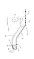
先ず、図1には、本発明に従う歩行者保護装置の一実施形態としての自動車の前面に設置されたフロントバンパの内側に取り付けられる歩行者保護装置が、その上面形態において、概略的に示されている。かかる図1から明らかなように、本実施形態の歩行者保護装置は、プレート部10を有している。
First, FIG. 1 schematically shows a pedestrian protection device attached to the inside of a front bumper installed on the front surface of an automobile as an embodiment of a pedestrian protection device according to the present invention in the form of its top surface. ing. As is clear from FIG. 1, the pedestrian protection device of this embodiment has a
このプレート部10は、例えば、ポリプロピレンやABS樹脂等の合成樹脂材料からなり、図1における左右方向で、歩行者保護装置の自動車への設置状態下において車幅方向、つまり自動車の左右方向に延びる方向(以下からは左右方向と言う)の寸法が、車幅よりも所定寸法だけ短く、且つ図1における上下方向で、自動車の前後方向に延びる方向(以下からは前後方向と言う)の寸法が、左右方向の寸法よりも十分に短くされた、全体として、略横長矩形状を呈する薄肉の平板材にて構成されている。
The
図1及び図2に示されるように、かかるプレート部10においては、後側の半分に満たない大きさの部分が、平板形態を呈し、歩行者保護装置の自動車への設置状態下において水平に広がる上面と下面とを備えた後側平板部12とされている。また、そのような後側平板部12を除く前側の部分のうち、前端側の部位が、後側平板部12に対して、それよりも高い位置で、平行に延びる平板形態を呈する前側平板部14とされている。更に、かかる前側部分の後端側部位、つまり前側平板部14と後側平板部12との間の中間部位が、前側平板部14の後端から後側平板部12の前端に向かって下傾して延び出して、それら両平板部14,12を一体的に連結する中間傾斜板部16とされている。
As shown in FIG. 1 and FIG. 2, in such a
そして、後側平板部12の左右方向中央部位の後端部には、板厚方向に貫通する、所定の固定ボルト等が挿通可能な挿通孔18が、左右方向に所定間隔をおいて複数(ここでは、3個)設けられている。後述するように、これら各挿通孔18に挿通された固定ボルトによって、プレート部10が、自動車に取り付けられるようになっている。このことから明らかなように、ここでは、後側平板部12にて、車両に取り付けられるべき、プレート部の後側部分が構成されている。
A plurality of
一方、プレート部10の前側平板部14と中間傾斜板部16には、それらの左右方向の両サイド部位を除いた中間部位に、補強ビード20の複数(ここでは、5個)が、左右方向に一定の距離を隔てて、互いに隣り合うように位置せしめられた状態で、一体的に設けられている。これら複数の補強ビード20は、何れも、プレート部10の上面から上方に突出し、前側平板部14の前後方向の中間部から中間傾斜板部16の後端に至るまで、同一高さで、前後方向に真っ直ぐに延びる長手矩形筐体状の全体形状を有している。換言すれば、下方に向かって開口するコ字状の車幅方向断面形状を有して、前側平板部14と中間傾斜板部16とに跨って、前後方向に真っ直ぐに延びる凹溝形態を呈している。
On the other hand, the front side
また、前側平板部14においては、補強ビード20の形成部位よりも前端側の部分に、薄肉平板形状を有して、前後方向に延びる前側補強リブ22の複数が、互いに左右方向に間隔を隔てて、一体的に立設されている。更に、互いに隣り合う補強ビード20同士の間にも、薄肉平板形状を有して、左右方向に延びる前側補強リブ22が、補強ビード20同士を連結するように、一体的に立設されている。
Moreover, in the front side
このように、補強ビード20や前側補強リブ22が、前側平板部14と中間傾斜板部16に設けられていることによって、それら前側平板部14と中間傾斜板部16とに対して、十分な補強構造が付与されている。このことから明らかなように、本実施形態では、補強ビード20と前側補強リブ22とにて、補強部が構成され、また、そのような補強ビード20と前側補強リブ22とが設けられた前側平板部14と中間傾斜板部16とにて、補強部が設けられたプレート部の前側部分が構成されている。
As described above, the reinforcing
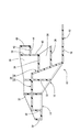
そして、かかる本実施形態の歩行者保護装置にあっては、図1及び図3から明らかなように、前側平板部14と中間傾斜板部16の補強ビード20や前側補強リブ22が設けられていない左右の両サイド部位に、それらが形成される中央部位よりも一段高くされた段差部24が、それぞれ設けられている。この段差部24も、その前側部分が、前側平板部14よりも更に高い位置で、後側平板部12や前側平板部14と平行に広がる側方平板部26とされている一方、後側部分が、側方平板部26の後端から後側平板部12の左右方向両端側部位の後端に向かって下傾して延び出して、それら側方平板部26と後側平板部12とを一体的に連結する側方傾斜板部28とされている。
In the pedestrian protection apparatus according to this embodiment, as is apparent from FIGS. 1 and 3, the reinforcing
そのような段差部24の側方平板部26の上面と下面には、前後方向と左右方向とにそれぞれ延び出して、互いに直交する薄肉平板状の第一補強リブ30と第二補強リブ32が、それぞれ、複数個ずつ一体形成されている。
On the upper surface and the lower surface of the side
一方、段差部24の側方傾斜板部28の上面(側方平板部26の上面と連続する面で、且つ後方に向かって位置する面)には、第一平行板部34と第二平行板部36とが、上下方向に所定距離を隔てた位置において、後方に向かって、互いに平行に且つ後側平板部12とも平行に延び出すようにして、一体形成されている。これら第一平行板部34と第二平行板部36は、何れも、側方平板部26と略同一の厚さ及び幅を有する矩形の平板形状を有しており、それぞれの後端側部分が、後側平板部12の上方において、後側平板部12と所定距離を隔てて、対向配置されている。
On the other hand, the first
そして、後側平板部12の上方に位置する、第一平行板部34の後端には、後側平板部12と直角な上方に向かって所定高さで延びる縦壁部38が、一体的に設けられている。この縦壁部38は、第一平行板部34や側方平板部26と略同一の厚さ及び幅を有する矩形の平板形状を有している。即ち、縦壁部38は、プレート部10に対して、後側平板部12の上方に位置するように一体形成されており、かかるプレート部10(歩行者保護装置)の自動車への設置状態下で、自動車の高さ方向に延び出し、且つ車幅方向に広がって、配置されるようになっている。そして、このような縦壁部38の後面が、縦壁部38の配置形態と同様に、プレート部10の自動車への設置状態下で、自動車の高さ方向に延び出し、且つ車幅方向に広がる後側接触面40とされている。
A
また、かかる縦壁部38は、側方平板部26に左右方向に延びるように設けられた複数の第二補強リブ32のうち、側方平板部26の後端側部位に位置する第二補強リブ32と、前後方向に所定距離隔てて対向配置されている。そして、この第二補強リブ32と縦壁部38との間には、側方平板部26に対して前後方向に延びるように設けられた第一補強リブ30が、側方平板部26から延長して延び出して、それら第二補強リブ32と縦壁部38とを相互に連結するように一体形成されている。第一平行板部34と第二平行板部36との間にも、第二補強リブ32と縦壁部38との間に延びる第一補強リブ30に対応位置して、前後方向に延びる第一補強リブ30が、第一及び第二平行板部34,36同士を連結するように、複数設けられている。これによって、第一及び第二平行板部34,36、更にはそれに一体形成された縦壁部38の変形強度が、有利に高められている。
Further, the
そして、そのような縦壁部38の後面の高さ方向中間部には、横壁部42が、後方に向かって、後側平板部12と平行に延びるようにして、一体形成されている。この横壁部42、縦壁部38と略同一の厚さ及び幅を有する矩形の平板形状を有している。即ち、横壁部42は、プレート部10に対して、後側平板部12の上方に位置するように一体形成されており、また、かかるプレート部10(歩行者保護装置)の自動車への設置状態下で、自動車の前後方向に延び出し、且つ車幅方向に広がって、配置されるようになっている。そして、このような横壁部42の下面が、横壁部42の配置形態と同様に、プレート部10の自動車への設置状態下で、自動車の前後方向に延び出し、且つ車幅方向に広がる下側接触面44とされている。
And the
換言すれば、本実施形態では、前後方向に延び出して、且つ左右方向に広がる平板の前側部分を下側に屈曲してなる如き形態を有する屈曲板部が、プレート部10の左右方向の両側端部に対して、後側平板部12の上方に位置するように、それぞれ一体形成され、それら各屈曲板部の上下方向に延びる前側部分にて、縦壁部38が構成されている一方、前後方向に延びる後側部分にて、横壁部42が構成されている。そして、それにより、上下方向に延びる縦壁部38の後側接触面40と、前後方向に延びる横壁部42の下側接触面44とにて、所定の角度(ここでは90°)で屈曲する、一つの連続した屈曲面からなるストッパ面が、プレート部10の左右方向の両側端部において、後側平板部12の上方に位置するように形成されているのである。
In other words, in the present embodiment, the bent plate portions having such a shape that the front portion of the flat plate extending in the front-rear direction and extending in the left-right direction is bent downward are provided on both sides of the
なお、横壁部42の後端には、上方に向かって、縦壁部38と平行に延びる補助壁部46が、縦壁部38の上端側部位と前後方向に所定距離を隔てて対向位置するように一体形成されている。そして、それら縦壁部38と補助壁部46との間にも、第二補強リブ32と縦壁部38との間に延びる第一補強リブ30に対応位置して、前後方向に延びる第一補強リブ30が、縦壁部38と補助壁部46とを互いに連結するように、複数設けられている。これによって、横壁部42の変形強度が、有利に高められている。
At the rear end of the
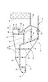
そして、かくの如き構造とされた本実施形態の歩行者保護装置は、例えば、図4に示されるような構造において、自動車の前部の下部部位に取り付けられる。 And the pedestrian protection apparatus of this embodiment made into such a structure is attached to the lower site | part of the front part of a motor vehicle in the structure as shown, for example in FIG.
すなわち、歩行者保護装置は、補強ビード20や前側補強リブ22が複数設けられたプレート部10の前側平板部14を自動車の前面から突出させて、その前端部を、図示しないフロントバンパのバンパカバー内に突入させる一方、プレート部10の後側後側平板部12を前後方向に水平に延出させて、かかる後側平板部12における後端部の上面を、自動車の前部に、車幅方向に延びるように固設された、ラジエータ48を支持するラジエータサポート50の下面に接触させた状態で、配置される。そして、後側平板部12の後端部に設けられた複数の挿通孔18に、固定ボルト52がそれぞれ1個ずつ挿通されて、それら各固定ボルト52がラジエータサポート50に螺入されることで、プレート部10の後側平板部12が、その後端部において、ラジエータサポート50に固定される。
That is, the pedestrian protection device projects the front
ここで、ラジエータサポート50には、各種の理由から、車幅方向の両側の各端部に、上方に向かって突出し、且つ車幅方向に広がる板状形態を呈する金属製の板状突部54が設けられる場合が多い。そこで、本実施形態の歩行者保護装置にあっては、ラジエータサポート50に取り付けられる取付部位たるプレート部10の後側平板部12上に位置して、上下方向に延びる縦壁部38の後側接触面40が、かかる板状突部54の先端に対して、それよりも水平方向の前方側に、所定距離を隔てて位置せしめられると共に、左右方向に延びる横壁部42の下側接触面44が、板状突部54の先端に対して、それよりも鉛直方向の上方に離間位置せしめられた状態で、プレート部10が、自動車の前部の下部部位に配置される。そして、そのような配置状態下で、上記の如く、プレート部10が、ラジエータサポート50に対してボルト固定される。
Here, for various reasons, the
かくして、歩行者保護装置が、自動車前面の下部部位に、前後方向に水平に延びるように配されて、プレート部10の前端部をバンパカバー内に突入させつつ、その全体が、バンパカバーに入力される衝撃荷重の入力方向を含む水平面に平行に延出位置せしめられるのである。
Thus, the pedestrian protection device is arranged at the lower part of the front surface of the automobile so as to extend horizontally in the front-rear direction, and the entire front end of the
従って、本実施形態の歩行者保護装置にあっては、自動車前面への設置状態下で、歩行者が自動車前面に衝突して、歩行者の脚部がフロントバンパのバンパカバーに接触乃至は衝突せしめられた際に、かかる歩行者の脚部が、バンパカバーを介して、プレート部10の前端部に接触する。このとき、プレート部10の前側平板部14と中間傾斜板部16とからなる前側部分が複数の補強ビード20と複数の前側補強リブ22とによって補強されているため、かかるプレート部10の前端部への衝撃荷重の入力により、プレート部10において生ずる衝撃荷重に対する反力が、歩行者の脚部に対して、瞬時に且つ確実に作用せしめられる。その結果、歩行者が、自動車のボンネットにて受け止められて、衝撃吸収が図られることで、歩行者の保護及び安全が効果的に図られ得るようになっているのである。
Therefore, in the pedestrian protection device according to the present embodiment, the pedestrian collides with the front of the automobile and the pedestrian's legs contact or collide with the bumper cover of the front bumper under the installation state on the front of the automobile. When squeezed, the leg portion of the pedestrian comes into contact with the front end portion of the
そして、かかる歩行者保護装置においては、特に、前述せる如く、プレート部10のラジエータサポート50への取付状態下で、上下方向に延びる縦壁部38の後側接触面40と左右方向、つまり車幅方向に延びる横壁部42の下側接触面44とが、ラジエータサポート50から延び出す板状突部54に対して、自動車の前方と上方とに離間位置せしめられて、かかる板状突部54の先端部をくわえ込むように配置される。
In such a pedestrian protection device, as described above, in particular, when the
このため、プレート部10の前端部への衝撃荷重の入力時には、図4に白抜きの矢印:アで示されるように、プレート部10を後方側向かって押圧する作用力によって、歩行者保護装置の全体が、主に、プレート部10の挿通孔18の内周面と固定ボルト52の外周面との間に存在するスキの分だけ、後方に変位させられるようになるが、このとき、図4に二点差線で示されるように、板状突部54の先端が、縦壁部38の後側接触面40に当接する。これによって、歩行者保護装置の後方への変位が規制されるようになる。
For this reason, when an impact load is input to the front end portion of the
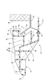
また、本実施形態の歩行者保護装置では、衝撃荷重の入力位置たるプレート部10の前端部が、プレート部10のラジエータサポート50への取付部位よりも高い位置にあるため、プレート部10の前端部への衝撃荷重の入力時に、プレート部10を後方側向かって押圧する作用力に加えて、図5に白抜きの矢印:イで示されるように、プレート部10を下側に向かって押圧する作用力が加えられる。それによって、歩行者保護装置の全体が、下側に変位させられるようになるが、このとき、図5に二点差線で示されるように、板状突部54の先端が、横壁部42の下側接触面44に当接し、以て、歩行者保護装置の下側への変位が規制されるようになる。
Moreover, in the pedestrian protection apparatus of this embodiment, since the front end part of the
そして、そのように、縦壁部38の後側接触面40と横壁部42の下側接触面44とに対する板状突部54の先端の当接によって、歩行者保護装置の後方側と下側への変位が規制されるようになっているところから、プレート部10の前端部への衝撃荷重の入力時に、プレート部10を後方や下方に押圧する押圧力に基づいて、図5に矢印:ウで示されるように、プレート部10の前端部を持ち上げる方向に、例えば、プレート部10の中間傾斜板部16と後側平板部12との境界の屈曲部やプレート部10のラジエータサポート50へのボルト固定部位を回転中心として回転させる回転力が加えられても、歩行者保護装置が、それらの屈曲部や固定部位を回転中心として回転させられることが、阻止されるようになる。
Then, the rear side and the lower side of the pedestrian protection device are brought into contact with the
しかも、縦壁部38と横壁部42とが、ラジエータサポート50に固定するための固定ボルト52が存在しないプレート部10の左右方向の両端側部位に設けられている。それ故、ラジエータサポート50に固定されないために、上記のプレート部10に対する回転力が発生し易いプレート部10の左右方向の両端側部位での回転が、より有効に規制される。
In addition, the
これによって、かかる歩行者保護装置では、プレート部10の前端部への衝撃荷重の入力によりプレート部10が回転させられるときに、その回転中心となり易い中間傾斜板部16と後側平板部12との境界の屈曲部分や、後側平板部12のラジエータサポート50への固定部位等において屈曲することが、効果的に防止されるようになっている。
Accordingly, in such a pedestrian protection device, when the
従って、かくの如き本実施形態の歩行者保護装置にあっては、歩行者の自動車前面への衝突時に生ずる衝撃荷重の入力時に、プレート部10の屈曲変形に起因して、歩行者保護性能が低下することが有利に防止され、以て、所望の歩行者保護性能が、極めて安定的に且つ確実に発揮され得ることとなるのである。
Therefore, in the pedestrian protection apparatus of this embodiment as described above, the pedestrian protection performance is caused by the bending deformation of the
また、本実施形態では、縦壁部38の前面と横壁部42の上面とに対して、第一補強リブ30が一体形成されて、それら縦壁部38と横壁部42の強度が有利に高められている。それ故、プレート部10に対する衝撃荷重の入力に起因したプレート部10の変位によって、縦壁部38や横壁部42が、ラジエータサポート50に設けられる板状突部54に当接した際に、そのときの衝撃により、それら縦壁部38や横壁部42が変形し、それが、プレート部10の変位規制に悪影響を及ぼすようなことが有利に防止され得る。その結果として、歩行者保護性能が、より安定的に発揮され得ることとなる。
In the present embodiment, the first reinforcing
さらに、本実施形態の歩行者保護装置においては、他の部位に比して、回転モーメントが発生し易いプレート部10の左右方向の両側の端部に、縦壁部38と横壁部42が設けられて、プレート部10の変位及び回転規制が図られているため、そのようなプレート部10の変位や回転に起因した屈曲変形が、更に確実に防止され、これによっても、より安定した歩行者保護性能が、更に確実に発揮され得るのである。
Furthermore, in the pedestrian protection device of the present embodiment, the
また、かかる歩行者保護装置では、プレート部10の前端部が、自動車に取り付けられるプレート部10の後端部よりも上側に位置せしめられているために、衝撃荷重の入力時に、プレート部10の回転が発生し易くなっているものの、縦壁部38と横壁部42とによるプレート部10の変位規制に基づいて、そのようなプレート部10の回転が有利に阻止され得る。それ故、優れた歩行者保護性能が効果的に確保され得る。
Moreover, in this pedestrian protection device, since the front end portion of the
以上、本発明の具体的な構成について詳述してきたが、これはあくまでも例示に過ぎないのであって、本発明は、上記の記載によって、何等の制約をも受けるものではない。 The specific configuration of the present invention has been described in detail above. However, this is merely an example, and the present invention is not limited by the above description.
例えば、縦壁部38と横壁部42は、プレート部10に対して、その後側部分に位置するように設けられておれば良い。従って、例えば、図6に示されるように、プレート部10の後側部分たる後側平板部12に対して、縦壁部38を上方に延びるように一体的に立設すると共に、この縦壁部38に対して、その上側部位から後方に延び出すように一体形成することも出来る。なお、図6に示された実施形態に関しては、図1乃至図5に示された前記実施形態と同一の構造とされた部材及び部位について、図1乃至図5と同一の符号を付すことにより、その詳細な説明は省略した。
For example, the
また、縦壁部38における横壁部42の形成位置は、板状突部54と接触する縦壁部38の後側接触面40が確保され得る位置ならば、特に限定されるものではない。即ち、横壁部42は、縦壁部38の下端部の除いた高さ方向中間部や上端部を含む上側部位のうちの何れの部位に設けられていても良いのである。
Moreover, the formation position of the
それら縦壁部38と横壁部42のプレート部10に対する形成位置は、板状突部54の配設位置に応じて適宜に変更され得るものである。それ故、縦壁部38と横壁部42は、例示されたプレート部10の左右方向両側端部に限らず、プレート部10の左右方向の中間部に設けられていても良く、或いは縦壁部38と横壁部42のうちの少なくとも何れか一方が、プレート部10の左右方向の幅と同一の幅を有して、プレート部10の全幅に亘って連続して広がるように形成されていても、何等差し支えない。
The formation positions of the
また、プレート部10の左右方向両側端部に設けられた段差部24は、本発明において必須のものではない。
Moreover, the
板状突部54の形状や形成位置も、例示のものに何等限定されるものではない。
The shape and the formation position of the plate-
プレート部10の前側部分に設けられる補強部は、例えば、補強ビードだけにて、或いは補強リブのみによっても構成され、更には、それら補強ビードや補強リブ以外の構造体等によっても構成され得る。なお、補強部を補強ビードや補強リブにて構成する場合にあっても、それら補強ビードや補強リブの全体形状や断面形状、或いは配設形態、配設個数等は、プレート10の大きさ等に応じて適宜に決定されるところである。
The reinforcement part provided in the front side part of the
プレート部10の全体形状も、例示された形状に、特に限定されるものではなく、例えば、屈曲部のない平板形状とされていても、何等差し支えない。
The overall shape of the
また、前記実施形態では、歩行者保護装置の全体が、合成樹脂材料を用いて形成されていたが、この歩行者用保護装置としての歩行者保護装置の材質は、何等これに限定されるものではなく、例えば、アルミニウムやアルミニウム合金等の比較的に軽量で、成形性に優れた金属材料を用いて構成することも出来る。 Moreover, in the said embodiment, although the whole pedestrian protection apparatus was formed using the synthetic resin material, the material of the pedestrian protection apparatus as this pedestrian protection apparatus is what is limited to this at all Instead, for example, a metal material that is relatively lightweight and excellent in formability, such as aluminum or an aluminum alloy, may be used.
さらに、車両前部の下部部位への歩行者用保護装置(歩行者保護装置)の設置構造も、例示の構造に、特に限定されるものではない。即ち、プレート部(プレート部10)の後側部分(後側平板部12)が固定される車両の部位や固定方式が、種々変更され得るのである。 Furthermore, the installation structure of the pedestrian protection device (pedestrian protection device) in the lower part of the front portion of the vehicle is not particularly limited to the illustrated structure. In other words, the vehicle portion and the fixing method to which the rear portion (rear flat plate portion 12) of the plate portion (plate portion 10) is fixed can be variously changed.
加えて、本発明は、自動車の前部の下部部位に取り付けられる歩行者保護装置と、かかる歩行者保護装置の自動車への取付構造の他、自動車以外の車両の前部の下部部位に取り付けられる車両用歩行者保護装置と、かかる車両用歩行者保護装置の車両への取付構造の何れに対しても、有利に適用され得るものであることは、勿論である。 In addition, this invention is attached to the lower part of the front part of vehicles other than a motor vehicle besides the pedestrian protection apparatus attached to the lower part of the front part of a motor vehicle, the attachment structure to the motor vehicle of this pedestrian protection device. Of course, the present invention can be advantageously applied to both the pedestrian protection device for vehicles and the structure for mounting the pedestrian protection device for vehicles on the vehicle.
以上、本発明の具体的な構成について詳述してきたが、これはあくまでも例示に過ぎないのであって、本発明は、各種の形態において実施され得るものである。従って、当業者の知識に基づいて採用される本発明についての種々なる変更、修正、改良に係る各種の実施の形態が、何れも、本発明の趣旨を逸脱しない限りにおいて、本発明の範疇に属するものであることが、理解されるべきである。 The specific configuration of the present invention has been described in detail above. However, this is merely an example, and the present invention can be implemented in various forms. Accordingly, various embodiments relating to various changes, modifications, and improvements of the present invention adopted based on the knowledge of those skilled in the art are all within the scope of the present invention without departing from the spirit of the present invention. It should be understood that it belongs.
10 プレート部 12 後側平板部
14 前側平板部 16 中間傾斜板部
20 補強ビード 22 前側補強リブ
30 第一補強リブ 32 第二補強リブ
38 縦壁部 42 横壁部
50 ラジエータサポート 44 板状突部
DESCRIPTION OF
Claims (4)
車両の高さ方向に延び出して、且つ車幅方向に広がる縦壁部が、前記プレート部に対して、前記後側部分に位置するように一体形成されていると共に、該縦壁部の上側部位から車両の後方に延び出して、且つ車幅方向に広がる横壁部が、該縦壁部に一体形成されていることを特徴とする車両用歩行者保護装置。 It is arranged at a lower part of the front part of the vehicle so as to extend in the front-rear direction of the vehicle, and is attached to the vehicle at the rear part, and has a plate part provided with a reinforcing part at the front part, A pedestrian protection device for a vehicle configured to protect the legs by contacting the legs of a pedestrian that has collided with the front of the vehicle at the front end,
A vertical wall portion extending in the vehicle height direction and extending in the vehicle width direction is formed integrally with the plate portion so as to be positioned at the rear side portion, and above the vertical wall portion. A pedestrian protection device for vehicles, wherein a lateral wall portion extending rearward from the part and extending in the vehicle width direction is formed integrally with the longitudinal wall portion.
請求項1乃至請求項3のうちの何れか1項に記載の車両用歩行者保護装置を用い、該車両用歩行者保護装置が取り付けられるべき車両の被取付部位に、上方に向かって突出し且つ車幅方向に広がる板状形態を有して設けられた剛性の板状突部に対して、該車両用歩行者保護装置の前記縦壁部の後面と前記横壁部の下面とが、該車両用歩行者保護装置の前記プレート部の前端部に対する前記歩行者の脚部の接触によって当接することにより、車両の後方と下方への該プレート部の変位が規制される位置に、該車両用歩行者保護装置を配置して、車両に取り付けることを特徴とする車両用歩行者保護装置の取付構造。
It is arranged at a lower part of the front part of the vehicle so as to extend in the front-rear direction of the vehicle, and is attached to the vehicle at the rear part, and has a plate part provided with a reinforcing part at the front part, A structure for attaching to a vehicle a pedestrian protection device for a vehicle configured to protect the leg by contacting the leg of a pedestrian that has collided with the front of the vehicle at the front end,
The vehicle pedestrian protection device according to any one of claims 1 to 3, wherein the vehicle pedestrian protection device is to be attached to a mounted portion of the vehicle and is projected upward. The rear surface of the vertical wall portion and the lower surface of the horizontal wall portion of the pedestrian protection device for a vehicle with respect to a rigid plate-shaped protrusion provided with a plate shape extending in the vehicle width direction are The vehicle pedestrian protection device is in a position where the displacement of the plate portion in the rearward and downward direction of the vehicle is restricted by contacting the pedestrian's leg with the front end of the plate portion. An installation structure for a pedestrian protection device for a vehicle, wherein the pedestrian protection device is arranged and attached to a vehicle.
Priority Applications (1)
| Application Number | Priority Date | Filing Date | Title |
|---|---|---|---|
| JP2008265505A JP5340690B2 (en) | 2008-10-14 | 2008-10-14 | Mounting structure for vehicle pedestrian protection device |
Applications Claiming Priority (1)
| Application Number | Priority Date | Filing Date | Title |
|---|---|---|---|
| JP2008265505A JP5340690B2 (en) | 2008-10-14 | 2008-10-14 | Mounting structure for vehicle pedestrian protection device |
Publications (2)
| Publication Number | Publication Date |
|---|---|
| JP2010095044A true JP2010095044A (en) | 2010-04-30 |
| JP5340690B2 JP5340690B2 (en) | 2013-11-13 |
Family
ID=42257046
Family Applications (1)
| Application Number | Title | Priority Date | Filing Date |
|---|---|---|---|
| JP2008265505A Expired - Fee Related JP5340690B2 (en) | 2008-10-14 | 2008-10-14 | Mounting structure for vehicle pedestrian protection device |
Country Status (1)
| Country | Link |
|---|---|
| JP (1) | JP5340690B2 (en) |
Cited By (3)
| Publication number | Priority date | Publication date | Assignee | Title |
|---|---|---|---|---|
| JP2012076536A (en) * | 2010-09-30 | 2012-04-19 | Fuji Heavy Ind Ltd | Pedestrian protecting device for vehicle |
| CN103079900A (en) * | 2010-10-08 | 2013-05-01 | 日产自动车株式会社 | Bumper for vehicle |
| JP2013203322A (en) * | 2012-03-29 | 2013-10-07 | Fuji Heavy Ind Ltd | Energy absorption bracket |
Citations (5)
| Publication number | Priority date | Publication date | Assignee | Title |
|---|---|---|---|---|
| JP2002274298A (en) * | 2001-03-15 | 2002-09-25 | Fuji Heavy Ind Ltd | Bumper structure for vehicle |
| JP2006273212A (en) * | 2005-03-30 | 2006-10-12 | Honda Motor Co Ltd | Vehicle front structure |
| JP2007055543A (en) * | 2005-08-26 | 2007-03-08 | Kojima Press Co Ltd | Pedestrian protecting device for vehicle |
| JP2007176338A (en) * | 2005-12-28 | 2007-07-12 | Kojima Press Co Ltd | Pedestrian protection device for vehicle |
| JP2007246044A (en) * | 2006-03-20 | 2007-09-27 | Mazda Motor Corp | Front structure of automobile |
-
2008
- 2008-10-14 JP JP2008265505A patent/JP5340690B2/en not_active Expired - Fee Related
Patent Citations (5)
| Publication number | Priority date | Publication date | Assignee | Title |
|---|---|---|---|---|
| JP2002274298A (en) * | 2001-03-15 | 2002-09-25 | Fuji Heavy Ind Ltd | Bumper structure for vehicle |
| JP2006273212A (en) * | 2005-03-30 | 2006-10-12 | Honda Motor Co Ltd | Vehicle front structure |
| JP2007055543A (en) * | 2005-08-26 | 2007-03-08 | Kojima Press Co Ltd | Pedestrian protecting device for vehicle |
| JP2007176338A (en) * | 2005-12-28 | 2007-07-12 | Kojima Press Co Ltd | Pedestrian protection device for vehicle |
| JP2007246044A (en) * | 2006-03-20 | 2007-09-27 | Mazda Motor Corp | Front structure of automobile |
Cited By (3)
| Publication number | Priority date | Publication date | Assignee | Title |
|---|---|---|---|---|
| JP2012076536A (en) * | 2010-09-30 | 2012-04-19 | Fuji Heavy Ind Ltd | Pedestrian protecting device for vehicle |
| CN103079900A (en) * | 2010-10-08 | 2013-05-01 | 日产自动车株式会社 | Bumper for vehicle |
| JP2013203322A (en) * | 2012-03-29 | 2013-10-07 | Fuji Heavy Ind Ltd | Energy absorption bracket |
Also Published As
| Publication number | Publication date |
|---|---|
| JP5340690B2 (en) | 2013-11-13 |
Similar Documents
| Publication | Publication Date | Title |
|---|---|---|
| JP4317203B2 (en) | Pedestrian protection device for vehicles | |
| US10596994B2 (en) | Front structure of vehicle | |
| JP5751238B2 (en) | Fender support structure | |
| JP4890113B2 (en) | Pedestrian protection device for vehicles | |
| US7478832B2 (en) | Knee bolster bracket structure of vehicle | |
| JP2010052729A (en) | Front structure of automobile | |
| JP4479550B2 (en) | Engine under cover mounting structure | |
| JP2009262778A (en) | Vehicular pedestrian protector | |
| JP5020519B2 (en) | Bumper structure for vehicles | |
| JP4479637B2 (en) | Bumper structure for vehicles | |
| JP2012116351A (en) | Front end structure of vehicle | |
| JP5340690B2 (en) | Mounting structure for vehicle pedestrian protection device | |
| JP4890114B2 (en) | Pedestrian protection device for vehicles | |
| JP5882163B2 (en) | Radiator grill | |
| JP2007168594A (en) | Pedestrian protection device for vehicle | |
| JP5004124B2 (en) | Pedestrian protection device for vehicles | |
| JP6514732B2 (en) | Pedestrian protection structure at the front of the vehicle | |
| JP2011246040A (en) | Pedestrian protecting device for vehicle | |
| JP6444824B2 (en) | Bumper absorber | |
| JP5109569B2 (en) | Front bumper structure | |
| JP4905678B2 (en) | Body structure at the front of the vehicle | |
| JP4797085B2 (en) | Shock absorption structure in the engine room | |
| JP5122310B2 (en) | Vehicle front bumper device | |
| JP2008110679A (en) | Bumper reinforcement of automobile | |
| JP2006056404A (en) | Underrun protector structure |
Legal Events
| Date | Code | Title | Description |
|---|---|---|---|
| A621 | Written request for application examination |
Free format text: JAPANESE INTERMEDIATE CODE: A621 Effective date: 20111004 |
|
| A131 | Notification of reasons for refusal |
Free format text: JAPANESE INTERMEDIATE CODE: A131 Effective date: 20121225 |
|
| A977 | Report on retrieval |
Free format text: JAPANESE INTERMEDIATE CODE: A971007 Effective date: 20121228 |
|
| A521 | Written amendment |
Free format text: JAPANESE INTERMEDIATE CODE: A523 Effective date: 20130225 |
|
| TRDD | Decision of grant or rejection written | ||
| A01 | Written decision to grant a patent or to grant a registration (utility model) |
Free format text: JAPANESE INTERMEDIATE CODE: A01 Effective date: 20130730 |
|
| A61 | First payment of annual fees (during grant procedure) |
Free format text: JAPANESE INTERMEDIATE CODE: A61 Effective date: 20130807 |
|
| R150 | Certificate of patent or registration of utility model |
Ref document number: 5340690 Country of ref document: JP Free format text: JAPANESE INTERMEDIATE CODE: R150 Free format text: JAPANESE INTERMEDIATE CODE: R150 |
|
| R250 | Receipt of annual fees |
Free format text: JAPANESE INTERMEDIATE CODE: R250 |
|
| R250 | Receipt of annual fees |
Free format text: JAPANESE INTERMEDIATE CODE: R250 |
|
| R250 | Receipt of annual fees |
Free format text: JAPANESE INTERMEDIATE CODE: R250 |
|
| R250 | Receipt of annual fees |
Free format text: JAPANESE INTERMEDIATE CODE: R250 |
|
| LAPS | Cancellation because of no payment of annual fees |