JP2010087265A5 - - Google Patents
Download PDFInfo
- Publication number
- JP2010087265A5 JP2010087265A5 JP2008255041A JP2008255041A JP2010087265A5 JP 2010087265 A5 JP2010087265 A5 JP 2010087265A5 JP 2008255041 A JP2008255041 A JP 2008255041A JP 2008255041 A JP2008255041 A JP 2008255041A JP 2010087265 A5 JP2010087265 A5 JP 2010087265A5
- Authority
- JP
- Japan
- Prior art keywords
- adhesive tape
- tape
- width direction
- tension
- chuck
- Prior art date
- Legal status (The legal status is an assumption and is not a legal conclusion. Google has not performed a legal analysis and makes no representation as to the accuracy of the status listed.)
- Pending
Links
- 239000002390 adhesive tape Substances 0.000 claims description 202
- 239000000758 substrate Substances 0.000 claims description 29
- 238000005304 joining Methods 0.000 claims description 20
- 238000003825 pressing Methods 0.000 claims description 6
- 230000001276 controlling effect Effects 0.000 claims description 3
- 235000012431 wafers Nutrition 0.000 description 73
- 230000001681 protective Effects 0.000 description 19
- 238000003475 lamination Methods 0.000 description 10
- 230000037303 wrinkles Effects 0.000 description 8
- 238000003860 storage Methods 0.000 description 7
- 239000004065 semiconductor Substances 0.000 description 5
- 239000000853 adhesive Substances 0.000 description 4
- 230000001070 adhesive Effects 0.000 description 4
- 238000000227 grinding Methods 0.000 description 3
- 238000011084 recovery Methods 0.000 description 3
- 239000007787 solid Substances 0.000 description 3
- 230000001429 stepping Effects 0.000 description 3
- 238000005520 cutting process Methods 0.000 description 2
- 238000010586 diagram Methods 0.000 description 2
- 238000004519 manufacturing process Methods 0.000 description 2
- 239000000463 material Substances 0.000 description 2
- 230000002093 peripheral Effects 0.000 description 2
- 229920002379 silicone rubber Polymers 0.000 description 2
- 239000004945 silicone rubber Substances 0.000 description 2
- 239000004821 Contact adhesive Substances 0.000 description 1
- 239000000969 carrier Substances 0.000 description 1
- 238000006243 chemical reaction Methods 0.000 description 1
- 230000000052 comparative effect Effects 0.000 description 1
- 230000000875 corresponding Effects 0.000 description 1
- 238000002788 crimping Methods 0.000 description 1
- 230000001419 dependent Effects 0.000 description 1
- 238000009826 distribution Methods 0.000 description 1
- 238000007667 floating Methods 0.000 description 1
- 238000000034 method Methods 0.000 description 1
- 230000003287 optical Effects 0.000 description 1
- 238000002360 preparation method Methods 0.000 description 1
- 230000007261 regionalization Effects 0.000 description 1
- 230000003578 releasing Effects 0.000 description 1
- 239000011347 resin Substances 0.000 description 1
- 229920005989 resin Polymers 0.000 description 1
- 238000007789 sealing Methods 0.000 description 1
- 238000004642 transportation engineering Methods 0.000 description 1
- 238000004804 winding Methods 0.000 description 1
Images


Description
本発明は、基板への接着テープ貼り付け装置に関する。さらに詳しくは、半導体ウエハ等の基板への接着テープの貼り付け時に接着テープの幅方向の張力を所定の張力に調整しながら基板へ貼り付ける基板への接着テープ貼り付け装置に関する。 The present invention relates Installing Ri lamination adhesive tape device to the substrate. More particularly, to adhesive tape pasted the width direction of the tension of the adhesive tape adhesive tape lamination joining apparatus with Ri to the substrate pasted to a substrate while adjusting the predetermined tension when on a substrate such as a semiconductor wafer.
従来より、半導体チップの製造工程で、パターンの形成されたウエハのパターン形成面に保護テープを貼り付けておき、その裏面を研削して薄厚化させた後、その研削面にダイアタッチフィルムを貼り付ける。続いてウエハのダイアタッチフィルム貼着面を下にして該ウエハをダイシングテープにマウントし、前記保護テープを剥離テープ等で剥離した後、該ウエハをダイシングしてチップ化することが行なわれている。この半導体チップを前記ダイアタッチフィルムを介してダイパッドにマウントし、封止樹脂で封止して半導体装置が形成されている。 Conventionally, in a semiconductor chip manufacturing process, a protective tape is applied to the pattern forming surface of a wafer on which a pattern is formed, the back surface is ground and thinned, and then a die attach film is applied to the ground surface. with that. Then the wafer was mounted on a dicing tape die attach film bonding surface of the wafer down to, after removing the previous SL protective tape peeling tape, it is made to be chips by dicing the wafer Yes. The semiconductor chip is mounted on a die pad via the die attach film and sealed with a sealing resin to form a semiconductor device.
上記のように半導体の製造工程においては、保護テープやダイアタッチフィルムといった各種の接着テープをウエハに貼り付けることが行なわれているが、接着テープの貼り付け時に適正な張力を持ってウエハ等の基板に貼り付けを行なわないと接着テープの残存応力によりウエハが反り、特に最近の薄厚化したウエハ(例えば100μm以下)では、反ったウエハが破損する場合がある。 As described above, in the semiconductor manufacturing process, various adhesive tapes such as a protective tape and a die attach film are attached to a wafer. If it is not attached to the substrate, the wafer warps due to the residual stress of the adhesive tape. In particular, in a recent thinned wafer (for example, 100 μm or less), the warped wafer may be damaged.
また、接着テープとして例えばウエハのパターン形成面上に貼り付けられる保護テープを用いる場合、その保護テープの貼り付けは、保護テープをウエハ上に引き出し、貼り付けローラで保護テープを押圧してウエハに貼り付け、その後、ウエハ外周に沿って保護テープを切断し、余剰部分の保護テープを剥離させて、この余剰部分の保護テープを巻き取って行なわれる。 In the case of using the protective tape pasted on the pattern formation surface of e.g. a wafer as an adhesive tape, paste the protective tape is pulled out the protective tape on the wafer, by pressing the protective tape Installing Ri pasting roller paste the wafer, then along the outer periphery of the wafer by cutting the protective tape, by peeling off the excess portion protective tape, Ru performed winds the protective tape of this excess portion.
しかし、上記の保護テープの貼り付けは、ウエハに保護テープを貼り付けた後、外周部分に沿って保護テープがくり貫かれるため、保護テープを巻き取る際に、未使用の保護テープ部分とくり貫かれて円形状の穴が開いた部分とで張力の差が生じ、穴が開いた部分の保護テープが幅方向に収縮して、未使用部分の保護テープがしわになってしまう問題があった。 However, since the protective tape is applied to the wafer after the protective tape is applied to the wafer, the protective tape is cut along the outer peripheral portion. There is a problem that the tension difference occurs between the part that penetrates and the circular hole is opened, and the protective tape of the part with the hole shrinks in the width direction, and the protective tape of the unused part is wrinkled. It was.
この状態でウエハに保護テープを貼り付けると、保護テープにしわや気泡が入り、裏面研削時にパターン面が汚染されたり、均一に研磨できない問題があった。 When a protective tape is applied to the wafer in this state, wrinkles and bubbles enter the protective tape, and there is a problem that the pattern surface is contaminated during the backside grinding or cannot be uniformly polished.
そこで、接着テープ供給ロールから引き出したテープを掛け渡すガイドローラに中央部が凸となるようなテーパーローラを使用し、接着テープの幅方向外側に向けて張力が働くようにした貼り付け装置が開示されている(例えば特許文献1)。 Therefore, by using the tapered low la as center protruding guide rollers to pass over the tape pulled out from the adhesive tape supply roll, lamination with Ri which is to work the tension outward in the width direction of the adhesive tape An apparatus is disclosed (for example, Patent Document 1).
また、接着テープが幅方向に弛まないよう接着テープの両端を把持した一対のテープチャックをシリンダの駆動で接着テープの幅方向外側に向けて互いに離反駆動させ、接着テープを幅方向に引っ張ることが知られている(例えば特許文献2)。 Also, contact adhesive tape drives away from each other a pair of tape chuck gripping the ends of the adhesive tape so as not to slacken in the width direction toward the outside in the width direction of the adhesive tape in the drive of the cylinder, pulling the adhesive tape in the width direction Is known (for example, Patent Document 2).
ところで、上記特許文献1の装置は、一定形状のテーパーローラを使用しているため、絶えず一定の張力でしかも外側方向に向かってしか張力を調整できない問題があり、接着テープの種類を交換する毎にテーパーローラの形状や材質等を見直し、テーパーローラを交換しなければならない問題がある。
However, apparatus of
また、接着テープの幅方向の張力調整ができないため、引っ張り張力が過剰な場合、接着テープの幅方向に残存応力が発生し、貼り付け後のウエハが反ったり、破損する場合があり、また、引っ張り張力が過小な場合、接着テープにしわが入ったり、気泡が入る問題がある。 In addition, because the tension in the width direction of the adhesive tape cannot be adjusted, if the tensile tension is excessive, residual stress occurs in the width direction of the adhesive tape, and the wafer after pasting may be warped or damaged. When the tensile tension is too small, there is a problem that the adhesive tape is wrinkled or bubbles are generated.
また、特許文献2のようにシリンダで強制的にテープチャックを接着テープの幅方向に引っ張って弛みを無くす方法は、シリンダでの一定の張力でしか張力を付与できず、接着テープの種類を変更するごとにシリンダ圧力の調整が必要となる問題や、細かい微調整ができないために引っ張り張力が過剰となったり、過小となったりする問題がある。
Also, as in
上記のように引っ張り張力が過小となった場合はテープ弛みが発生し、貼り付け時にしわが入ったり、気泡が入ったりする問題があり、接着テープとして保護テープを用いる場合は裏面研削時に均一に研磨できない問題や、接着テープとしてダイアタッチフィルムを用いる場合ではダイボンド時に接着不良が発生する場合がある。 If the tensile tension is too low as described above, tape loosening will occur, causing wrinkles or air bubbles when sticking, and when using protective tape as adhesive tape, it will be uniform during back grinding. In the case of using a die attach film as a problem that cannot be polished or as an adhesive tape , adhesion failure may occur during die bonding.
また、接着テープとしてドライフィルムレジストを用いる場合、厚みが30μm程度のものもあり、微小な幅方向への張力制御を行わなければ、容易にしわが入ってしまい、適用できない問題がある。 In addition, when a dry film resist is used as an adhesive tape , there are some having a thickness of about 30 μm, and there is a problem that wrinkles easily occur unless the tension control in a minute width direction is performed, and cannot be applied.
また、シリンダに代えてボールネジを使用し、テープチャックを所定量幅方向へ駆動して制御することも考えられるが、ボールネジのピッチでしか駆動できず、微細な駆動が困難であり、微細な幅方向への張力制御が困難となる問題がある。 In addition, it is conceivable to use a ball screw instead of the cylinder and drive the tape chuck in the width direction by a predetermined amount to control it. However, it can be driven only with the pitch of the ball screw, and it is difficult to drive finely. There is a problem that it is difficult to control the tension in the direction.
請求項1の発明は、その上面に基板を吸着保持する貼り付けテーブルと、前記基板より広幅でロール状に巻き回された接着テープの幅方向両側付近を把持する左右一対のテープ把持部材を備え、該テープ把持部材で該接着テープを把持しながら所定量基板上に引き出すテープチャック機構と、この引き出した接着テープを押圧して該基板に貼り付ける貼り付けローラとを備える基板への接着テープ貼り付け装置であって、
前記両テープ把持部材は、
それぞれが前記接着テープの上面側に位置する上側チャックと該接着テープの下面側に位置する下側チャックからなり、前記両チャック間での該接着テープの把持と該接着テープの幅方向に沿った互いの接近離反動が可能に構成され、
前記テープチャック機構は、
前記左右のテープ把持部材を接着テープの幅方向内側に向けて付勢する弾性部材と、
前記左右のテープ把持部材を互いに接近離反駆動させるとともに接着テープを把持した際に該接着テープの幅方向に働く張力をトルク値として検出するモータとを備え、
前記接着テープをテープ把持部材で把持する際に上側チャックと下側チャックとが接着テープの幅方向に沿って前記弾性部材で内側端に位置するように付勢された状態で上側チャックと下側チャックとで接着テープを把持するとともに前記モータで所定のトルク値となるように左右のテープ把持部材を互いに離反動させることにより該接着テープの幅方向への張力が所定の張力となるように制御しながら基板に接着テープを貼り付けるようにした基板への接着テープ貼り付け装置である。
The invention of
The both tape gripping members are
Each comprises an upper chuck located on the upper surface side of the adhesive tape and a lower chuck located on the lower surface side of the adhesive tape, and the grip of the adhesive tape between the chucks and along the width direction of the adhesive tape It is configured to be able to move toward and away from each other,
The tape chuck mechanism,
An elastic member for biasing the tape-holding member before Symbol left toward the inner side in the width direction of the adhesive tape,
And a motor to detect a torque value the tension acting in the width direction of the adhesive tape when gripping the adhesive tape causes the dynamic drive closer away counter to one another tape grip members of said left and right,
Upper side chuck and down in a state where the upper chuck and the lower chuck is energized so as to be positioned inner end by the elastic member along the width direction of the adhesive tape when gripping the adhesive tape by the tape gripping member The adhesive tape is gripped by the side chuck, and the left and right tape gripping members are moved away from each other so that a predetermined torque value is obtained by the motor so that the tension in the width direction of the adhesive tape becomes a predetermined tension. control while an adhesive tape stuck joining apparatus with Ri to the substrate so as to paste the adhesive tape to the substrate.
上記のような構成を採用することで接着テープを把持する際に幅方向への張力をモータでトルク値として検出しながら絶えず適正な張力に保つことができる。 By adopting the above-described configuration, it is possible to constantly maintain an appropriate tension while detecting the tension in the width direction as a torque value with a motor when gripping the adhesive tape.
使用するモータにはトルク値の検出が可能なステッピングモータやサーボモータ等が好ましく使用できる。 As the motor to be used, a stepping motor, a servo motor or the like capable of detecting a torque value can be preferably used.
また、請求項2の発明は、前記弾性部材の接着テープ幅方向内側に向けての付勢力は、前記左右のテープ把持部材が接着テープの幅方向へ接近離反動する際の摺動抵抗よりも大きく、かつ前記接着テープの幅を所定幅に保つために必要な張力よりも低く設定されている請求項1に記載の基板への接着テープ貼り付け装置である。
Further, in the invention of
上記のように、前記弾性部材の接着テープ幅方向内側に向けての付勢力を、前記左右のテープ把持部材が接着テープの幅方向へ接近離反動する際の摺動抵抗よりも大きく、かつ前記接着テープの幅を所定幅に保つために必要な張力よりも低く設定することで、微小な接着テープの幅方向への張力をテープ把持部材の接近離反動時の摺動抵抗に左右されずにモータでのトルク値の検出が可能となる。また、左右のテープ把持部材の接着テープ幅方向への接近離反動の摺動抵抗を限りなくゼロに近づけるように小さくしておけば、微小な接着テープの幅方向への張力をテープ把持部材の接近離反動時の摺動抵抗に左右されずにモータでのトルク値の検出が可能となる。 As described above, the urging force of the elastic member toward the inner side in the adhesive tape width direction is larger than the sliding resistance when the left and right tape gripping members approach and separate in the width direction of the adhesive tape, and the width of the adhesive tape by setting lower to than the tension required to keep a predetermined width is dependent tension in the width direction of the micro-adhesive tape to the sliding resistance when approaching away recoil tape gripping member Therefore, it is possible to detect the torque value at the motor. Further, if reduced to as close to zero as possible the sliding resistance of the approaching away reaction to the adhesive tape width direction of the left and right of the tape-holding member, tension tape in the width direction of the small adhesive tape The torque value at the motor can be detected without being influenced by the sliding resistance when the gripping member approaches and separates .
さらに、弾性部材の接着テープ幅方向内側に向けての付勢力を左右のテープ把持部材が内側端に復帰する程度に小さく設定しておけば、微小な接着テープの幅方向への張力をモータでのトルク値として検出可能となる。 Furthermore, if the biasing force of the elastic member toward the inner side in the adhesive tape width direction is set so small that the left and right tape gripping members return to the inner ends, the tension in the width direction of the minute adhesive tape can be adjusted with a motor. The torque value can be detected.
前記テープチャック機構を前記接着テープの上面側に位置する上側チャックと該接着テープの下面側に位置する下側チャックとからなり前記両チャック間での該接着テープの把持と該接着テープの幅方向に沿った互いの接近離反動が可能な左右一対のテープ把持部材と、前記左右のテープ把持部材を接着テープの幅方向内側に向けて付勢する弾性部材と、 左右のテープ把持部材を互いに接近離反駆動させるとともに接着テープを把持した際に該接着テープの幅方向に働く張力をトルク値として検出するモータとから構成され、前記接着テープをテープ把持部材で把持する際に上側チャックと下側チャックとが接着テープの幅方向に沿って前記弾性部材で内側端に位置するように付勢された状態で上側チャックと下側チャックとで接着テープを把持するとともに前記モータで所定のトルク値となるように左右のテープ把持部材を互いに離反動させることにより該接着テープの幅方向への張力が所定の張力となるように制御しながら基板に接着テープを貼り付けるようにしたので、接着テープをテープ把持部材でチャックした際に絶えず設定した張力で接着テープを保持でき、接着テープの貼り付けられた基板が接着テープの残存応力によって反ったり、破損したりすることがない。 The adhesive tape gripping the said adhesive tape with the tape chuck mechanism between the chucks composed of a lower chuck you position the lower surface of the upper side chuck and said adhesive tape you position the upper surface of the adhesive tape a pair of left and right tape-holding member capable of approaching away recoil of each other along the width direction of the elastic member for urging the tape-holding member of the right and left in the width direction inner side of the adhesive tape, the right and left tape gripping member is composed of a motor for detecting the tension acting in the width direction of the adhesive tape as a torque value at the time of holding the adhesive tape together to close the release counter-drive motion to each other, the upper and the adhesive tape when gripped by tape-holding member the adhesive tape between the upper side chuck and the lower chuck while the chuck and the lower chuck is energized so as to be positioned inner end by the elastic member along the width direction of the adhesive tape Adhesive tape to the substrate while gripping and controlling the tension in the width direction of the adhesive tape to be a predetermined tension by moving the left and right tape gripping members apart from each other so that a predetermined torque value is obtained by the motor since such a paste, the adhesive tape can hold adhesive tape tension constantly set upon chucked by tape-holding member, pasted substrate of the adhesive tape is warped by residual stress of the adhesive tape, broken There is nothing to do.
また、テープチャック機構の左右のテープ把持部材の接着テープ幅方向への接近離反動の摺動抵抗を限りなくゼロに近づけ、弾性部材の接着テープ幅方向内側に向けての付勢力を左右のテープ把持部材が内側端に復帰する程度に小さく設定することで、接着テープを把持した際に接着テープの幅方向に働く微小な張力をトルク値としてモータで検出でき、微小な範囲での接着テープ幅方向の張力を制御することが可能となる。 Also, the sliding resistance of the tape gripping mechanism's left and right tape gripping members approaching and moving back and forth in the adhesive tape width direction is as close to zero as possible, and the urging force of the elastic member toward the inner side of the adhesive tape width direction is applied to the left and right tapes. By setting it so small that the gripping member returns to the inner end, the minute tension acting in the width direction of the adhesive tape when gripping the adhesive tape can be detected by the motor as a torque value, and the width of the adhesive tape in a minute range It becomes possible to control the tension in the direction.
上記により、ローテンションで接着テープを基板に貼り付けることが可能となり、薄厚化されたウエハであっても、貼り付け時の接着テープに残存応力が発生せず、貼り付け後のウエハが反ったり、破損したりすることがない。 With the above, it becomes possible to attach the adhesive tape to the substrate with low tension, and even when the wafer is thinned, no residual stress is generated in the adhesive tape at the time of attachment, and the wafer after attachment is warped. No damage or damage.
また、予め設定した適正な張力となるようにテープ把持部材の接着テープ幅方向への張力を付与するように制御しながら接着テープを基板上に引き出すことができ、さらに適正な張力を保持した状態で基板に接着テープを貼り付けるようにしたので、極薄のドライフィルムレジスト(例えば50μm以下)のような接着テープであっても基板に貼り付けた際に気泡が入ったり、しわが入ったりすることがない。 In addition, the adhesive tape can be pulled out onto the substrate while controlling to apply the tension in the width direction of the adhesive tape of the tape gripping member so that the appropriate tension is set in advance. Since the adhesive tape is attached to the substrate, bubbles or wrinkles may occur when it is attached to the substrate even if it is an extremely thin dry film resist (for example, 50 μm or less). There is nothing.
また、接着テープの貼り付け時においても幅方向への張力を保持するようにしているので、貼り付けローラが作用する際に働く幅方向への張力も適正に制御され、しわが入ったり、収縮力が働いたりすることがない。 Also, since to hold the tension in the width direction even when affixed to the adhesive tape, is tension also properly controlled in the width direction of the Installing Ri bonded roller acts upon acts, or contains wrinkles , Contraction force does not work.
以下に本発明の接着テープ貼り付け装置の一実施形態について図1乃至図9に基づいて説明する。なお、図中においてウエハ3及び接着テープ6は、理解を容易にするために誇張して描いてある。
Be described with reference to FIGS. 1 to 9 for the embodiment of an adhesive tape joining with Ri joining apparatus of the present invention will be described below. In the figure, the
図1のように接着テープ貼り付け装置1は、機台5上に接着テープ6を貼り付ける前のウエハ3を収納するウエハ収納部4と、ウエハ3の位置決めを行なうアライメント部22と、ウエハに接着テープ6を貼り付ける接着テープ貼り付けユニット2と、接着テープ6が貼り付けられた貼り付け済ウエハ47を収納する貼り付け済ウエハ収納部48と、ウエハ収納部4からウエハ3を1枚ずつ取り出して搬送する搬送ロボット7から構成されている。
Adhesive tape joining joining
前記ウエハ収納部4は、ウエハ3を多段状に収納するカセットで構成され、適宜な昇降手段により前記カセットが昇降動するようになっており、搬送ロボット7の吸着ハンドが進入して、ウエハ3を1枚ずつ吸着して取り出すようになっている。
The
搬送ロボット7は、先端部に吸着ハンドが設けられており、この吸着ハンドは伸縮と回転が自在に構成され、ウエハ収納部4から取り出したウエハ3をアライメント部22及び接着テープ貼り付けユニット2の貼り付けテーブル40上へと搬送するとともに接着テープ6の貼り付けが完了した貼り付け済ウエハ47を貼り付け済ウエハ収納部48へと搬送して収納するようになっている。
Carrier robot 7 is suction hand is provided at the distal end portion, the suction hand has stretch and rotation is constituted freely, the
アライメント部22は、ウエハ6をその上面で吸着し、図示しない適宜な駆動源で回転される回転テーブル8と、前記回転テーブル8で回転されるウエハ6の外周部分に設けられたノッチやオリフラを適宜な光学手段等で検出するアライメントセンサ9が設けられている。
The
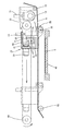
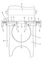
図1及び図2のように接着テープ貼り付けユニット2は、位置決めされたウエハ3をその上面で吸着保持する貼り付けテーブル40と、広幅でロール状の接着テープ6を供給する接着テープ供給リール11と、接着テープ6から剥離ローラ49で剥離されるセパレータ10を巻取るセパレータ巻取リール12と、接着テープ6を把持して引き出すテープチャック機構16と、引き出された接着テープ6をウエハ3に押圧して接着する貼り付けローラ14と、ウエハ3に貼り付けられた接着テープ6をウエハ3の円周方向に沿って切断するカッターユニット41と、切断された余剰部分の接着テープ6を巻取って回収する接着テープ回収リール13とから構成されている。
Figure 1 and the adhesive tape joining only
図2及び図3のように貼り付けテーブル40は、その上面でウエハ3を吸着保持するようになっており、機台5上に立設されたレール52と貼り付けテーブル40の垂直下方に設けられた支持枠51に設けられたスライダ53とが摺動可能に嵌合しており、機台5上に設けられたシリンダ50が作用して貼り付けテーブル40は昇降動するようになっている。
Only table with Ri bonded as shown in FIGS. 2 and 3 40 is adapted to place the
なお、ウエハ3の接着テープ6の貼り付け面と貼り付けテーブル40の外周上面の高さは、貼り付け条件に応じて適宜調整すればよく、外周、内周のテーブル面の高さは適宜な公知手段により調整可能にしておけば良い。
The height of the upper surface of an outer periphery of the attachment surface and bonded only table 40 with Ri of the
また、接着テープ供給リール11から引き出された接着テープ6はガイドローラ74を経由してテンションローラ54に導かれ、このテンションローラ54の位置が平行に保たれるよう制御して引き出し方向のテープ張力が適正に保たれ残存応力が発生しないようになっている。
Further, the
なお、上記の接着テープ6の引き出し時の張力は、自然な力で幅方向への収縮が発生しない程度の力で行なわれる。
The tension when the
前記接着テープ6は剥離ローラ49により、粘着面を保護しているセパレータ10が剥離されセパレータ巻取リール12に巻き取られる。この時、セパレータ10の巻取張力はテンションローラ55により制御され、接着テープ6からセパレータ10を剥離する際に接着テープ6に及ぶ張力を最小限に保つようになっている。なお、セパレータ10が使用されない接着テープ6も使用できる。
The
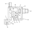
また、前記テープチャック機構16は、図1乃至図6のように支持枠56と支持枠57の内側に設けられている。また、前記テープチャック機構16は、前記支持枠56、57の間に前記両支持枠56、57と平行に設けられた支持枠32及び支持枠33と、これらの両支持枠32、33間に懸架された支持枠26とで形成されている。
The
また、前記両支持枠32、33の外側にはスライダ55、55が設けられており、これらスライダ55、55が、支持枠56と支持枠57の内側に設けられたレール54、54と摺動可能に嵌合することで、前記テープチャック機構16がレール54、54に沿って水平動するようになっている。また、前記支持枠57の外側にこの支持枠57に沿って無端ベルト34が設けられ、駆動プーリ59と従動プーリ61との間に張架されている。前記駆動プーリ59は、支持枠57に固定枠を介して固定されたモータ60の軸に接続され、前記ベルト34が前記モータ60の駆動により、回転駆動されるようになっている。前記テープチャック機構16の支持枠33の外側上方には支持板が外側に向けて延設され、この支持板が、支持枠57の開口部を介して前記ベルト34に締結されており、前記モータ60を駆動することで前記テープチャック機構16がレール54、54に沿って図5の実線位置から二点鎖線位置までを水平動するようになっている。
Further, the and the
また、前記両支持枠32、33の下端には、軸30が両支持枠32、33に対して回転可能に軸支され、この軸30の両支持枠32、33間の左右にはロール形状の一対の下側チャック25、25が軸30に対して摺動可能に設けられるとともに前記左右の下側チャック25、25は軸30に対して反時計回りにのみ回転するように図示しない係合ピン等が設けられている。
A
また、これらの左右の下側チャック25、25の間には剥離ローラ24が軸30に固定されており、この剥離ローラ24は左右の下側チャック25、25とともに軸30の回転に伴って共に回転するようになっている。なお、下側チャック25、剥離ローラ24は、接着テープ6の粘着面に接するので離型作用のあるシリコーンゴム等で形成することが好ましい。
Further, a peeling
また、軸30は、支持枠33を貫通して、その一端にギア35が固定されている。前記支持枠33の外側には前記軸30と平行に軸75が設けられ、その一端は支持枠33に軸支されている。前記軸75の他端側にはギア36が固定され、前記ギア35と係合している。
The
また、このギア35と軸30には図示しない適宜なクラッチ機構が設けられており、テープチャック機構16で接着テープ6を把持して引き出す際は、クラッチが切れて軸30は回転しないようになっており、後述する余剰部分の接着テープ6を貼り付けテーブル40から剥離する際にはクラッチが繋がって軸30が回転駆動されるようになっている。
The
また、前記ギア36の上方には支持枠57の外側に並設されたラック38及びギア36と係合するピニオン37が設けられ、このピニオン37は支持枠33の外側に軸支されたピニオン軸76の一端に設けられている。
Above the
従って、テープチャック機構16の接着テープ6の引き出し方向への往動時には軸30は回転せず、復動時は軸30が反時計回りに回転するようになっている。
Accordingly, the
また、上記左右の下側チャック25、25の外側には、ばね等の弾性部材18、18が設けられて左右の下側チャック25、25をストッパ70、70に向けて付勢しており、図7のように左右の下側チャック25、25はストッパ70、70に当接する内側端67、67に位置するようになっている。
Further, on the outside of the left and right
この弾性部材18の付勢力は、上記内側端67、67に復帰する程度の付勢力(例えばバネ定数0.01kg/mm以下。但し下側チャック25の重量や軸30の摺動抵抗により適宜選定すれば良い。)で、軸30の摺動抵抗も限りなくゼロに近づくようにしておくことが、テープチャック機構16で極僅かな幅方向への張力を制御する上で好ましい。
Biasing force of the
上記軸30の摺動抵抗や弾性部材18の付勢力が大きい場合、それを打ち消すだけのモータ20でのトルク付与が必要であり、接着テープ6の幅方向に与える張力が上記摺動抵抗及び付勢力よりも微小な場合、モータ20でその幅方向への張力を検出することができないからである。
When the sliding resistance of the
また、上記左右の下側チャック25、25の各々上方にはL字形状の上側チャック17、17が設けられ、左右の上側チャック17、17は後方にスライダ28が設けられてスライドガイド27前方の支持板31に敷設されたレール29と摺動可能に嵌合し、上下動可能になっている。
Further, L-shaped upper chucks 17 and 17 are provided above the left and right
また、上側チャック17は、図6のようにその上方が支持枠68に設けられたシリンダ19の軸と接続され、前記シリンダ19の駆動により上下動可能になっており、前記上側チャック17が下降した際に上側チャック17と下側チャック25との間で接着テープ6を把持するようになっている。また、前記上側チャック17と下側チャック25とでテープ把持部材69が形成されている。
The
なお、上側チャック17のテープ把持面はシリコーンゴム等滑りを防止する部材を設けておけば良い。
Note that the tape gripping surface of the
また、前記スライドガイド27は支持枠32と支持枠33の間に接着テープ6の幅方向に沿って懸架された上下2本のレール軸23、23に摺動可能に設けられており、前記スライドガイド27が支持枠68に取り付けられることにより上側チャック17が両レール軸23、23に沿って接着テープ6の幅方向に水平動可能になっている。
The
また、前記左右両側の支持枠68、68は図4乃至図6のように後方がベルト21に互いに上下対称となるように接続され、このベルト21を駆動することで、両支持枠68、68を介して左右の上側チャック17、17が接近離反動するようになっている。なお、前記ベルト21は、滑りが発生しないようにタイミングベルトが好ましく使用される。
Further, the left and right support frames 68 and 68 are connected to the
また、ベルト21は、トルク値を検出可能なモータ20にプーリを介して接続されており、このモータ20を予め設定したトルク値となるように駆動することで、左右の上側チャック17、17と下側チャック25、25が接着テープ6を把持した状態で幅方向に駆動され、接着テープ6に所定の張力が掛かるように制御される。
Further, the
上記モータ20は例えばステッピングモータ、サーボモータ等、トルク値を検出可能なモータが適宜利用できる。
As the
また、レール軸23に対するガイド27の摺動抵抗及び軸30に対する下側チャックの摺動抵抗は限りなく小さくゼロに近づくようにすることがモータ20で微小なトルク値を検出する面で好ましい。
Further, it is preferable that the sliding resistance of the
また、弾性部材18の下側チャック25の付勢力は、下側チャック25がストッパ70と当接する内側端67に復帰する程度に小さくすることが、モータ20で微小なトルク値を検出する面で好ましい。
Further, the biasing force of the
また、前記貼り付けローラ14は、適宜な支持枠に軸支され、シリンダ71によって上下動可能に設けられるとともに、前記支持枠の一端は、支持枠57の開口部を介してベルト66と接続されている。
Also, the
前記ベルト66は、支持枠57の後方に設けられたモータ64の駆動プーリ63と従動プーリ65に掛け渡されており、モータ64を駆動することで前記貼り付けローラ14が貼り付けテーブル40上を往復動するようになっている。
The
また、前記貼り付けローラ14は下降時に接着テープ6上を押圧転動しながらウエハ3に圧着して貼り付けるようになっている。なお、接着テープ6の種類に応じて適宜貼り付けローラ14にヒータを内蔵すれば良い。
Further, said
また、貼り付けローラ14の前方には接着テープ6の引き出し時に接着テープ6が加熱された貼り付けローラ14と接しないようにガイドするガイドローラ15が設けられている。なお、貼り付けローラ14を加熱しない場合は、ガイドローラ15を設けなくても良い。
The
また、上記カッターユニット41は、上記貼り付けテーブル40の上方に設けられ、カッター46と、このカッター46をウエハ3の外形に沿った円周方向に駆動するモータ45と、前記モータ45を支持する支持枠44と、この支持枠44を昇降動させることで前記カッター46を昇降動させるシリンダ43とから構成されている。前記支持枠44の下方には、モータ45が設けられ、モータ45の軸と接続された支持板にカッター46が設けられている。前記モータ45を駆動することでウエハ3の外周に沿って円周方向に接着テープ6を切断するようになっている。なお、適宜オリフラ用のカッターやノッチ用のカッターを設けても良い。
Moreover, the
また、前記支持枠44は後方にスライダ73が設けられ、前記スライダ73は、支持枠57の上下方向に敷設されたレール72と摺動可能に嵌合している。また、前記モータ45の固定された支持枠44は、支持枠57に固定された支持板42上に設けられたシリンダ43と接続されており、このシリンダ43の駆動で、カッターユニット41は貼り付けテーブル40に対して昇降動可能になっている。
Further, the
また、前記接着テープ回収リール13は、テープチャック機構16に設けられた剥離ローラ24及び下側チャック25、25で剥離された不用部分の接着テープ6を巻き取って回収するようになっており、接着テープ供給リール11及びテンションローラ54と連動して接着テープ6の引き出し方向に必要以上の張力が掛からないように制御されるようになっている。
The adhesive
以上が本発明の接着テープ貼り付け装置1の構成であり、次に本発明のテープチャック機構16部の動作機構について図7に基づいて説明する。
The above is the configuration of the adhesive tape joining
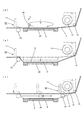
図7の実線位置のように接着テープ6がウエハ3に貼り付けられた後、接着テープ6がカッターユニット41の作用でウエハ3の外形に沿って切断されてくり貫かれるので、くり貫き部分と未使用部分の間で該接着テープ6に張力分布に差が生じ、接着テープ6が幅方向に収縮する。
After the
なお、次の貼り付けに際し、接着テープ6をテープ把持部材69で把持する位置は、接着テープ6が幅方向に収縮した位置を避ける方が、幅方向の張力の影響を受けないようにする点で好ましいが、前記接着テープ6の捨て代を少なくして有効に利用するためには、テープ把持部材69で接着テープ6を把持する位置は次の貼り付け時に影響しない程度に接近させることが好ましいので、図7及び図8(a)のように接着テープ6のくり貫き部分のテープ送り方向後方側寄りの一部を把持することになる。
It should be noted that the position where the
上記のように接着テープ6が幅方向に収縮した状態で、下側チャック25、25及び上側チャック17、17が内側端67、67に寄った状態(すなわち、接着テープ6の幅方向内側に向けてはテープチャック機構16の幅方向への引張力が発生しない状態)で上側チャック17、17をシリンダ19の作用で閉じ、接着テープ6をテープ把持部材69、69でチャックして把持する。
With the
次に、モータ20を作用させ、予め設定された所定のトルク値(上記接着テープ6のくり貫き部の幅が未使用部分の幅となる程度)となるように制御することで、図中二点鎖線位置のように接着テープ6の幅が所定の幅となるように幅方向の張力が制御される。
Next, the
上記の状態で、接着テープ6を貼り付けテーブル40上に保持されたウエハ3上に引き出し、幅方向の張力を保持した状態で後述する接着テープ6の貼り付けが行なわれるので
、テープ把持部材69で把持した接着テープ6の送り方向後方側の幅方向への張力が適正に保たれる。従って、接着テープ6の引き出し時及びウエハ3への貼り付け時に絶えず接着テープ6の幅方向への張力が適正に保たれ、残存応力によるウエハ3の反りや破損が発生せず、さらに接着テープ6にしわや気泡が入らないように貼り付けを行うことができる。
In the above state, the drawer on the
次に接着テープ貼り付け装置1での接着テープ6の基板への接着について以下に説明する。
It will be described below adhesion to the substrate of the
図1のように貼り付け前ウエハ収納部4を適宜な機構で昇降動作させ、搬送ロボット7の吸着ハンドの上面でウエハ3を1枚ずつ吸着させて取り出し、アライメント部22の吸着テーブル8上に移載する。
Is moved up and down by an appropriate mechanism to only front
吸着テーブル8上に移載されたウエハ3は吸着テーブル8上に吸着保持され、図示しない適宜な回転機構で回転駆動されて、ウエハ3の外周に設けられたノッチやオリフラをアライメントセンサ9で検出して、次の接着テープ6の貼り付け工程に備えて位置決めが行なわれる。
The
上記位置決めが行なわれたウエハ3は接着テープ貼り付けユニット2の貼り付けテーブル40上に位置決めされた状態で移載され、前記貼り付けテーブル40に吸着保持される。
次に、図8及び図9に基づいて、接着テープ貼り付けユニット2でのウエハ3への接着テープ6の貼り付け動作について説明する。
Next, with reference to FIGS. 8 and 9, it will be described pasting operation of the
図8(a)のように、テープチャック機構16が、水平動して、接着テープ6の把持位置まで移動し、テープ把持部材69の上側チャック17がシリンダ19の作用で下降して接着テープ6を該上側チャック17と下側チャック25で把持し、接着テープ6を保持する。この時、左右の下側チャック25、25は、接着テープ6を把持する直前まで弾性部材18による極僅かな付勢力でそれぞれストッパ70、70に向けて付勢されているので、両下側チャック25、25が内側端67、67に設けられたストッパ70、70にそれぞれ当接した状態で接着テープ6が把持され、接着テープ6の幅方向外側に向けては張力が発生しない。
As shown in FIG. 8A, the
次にモータ20を予め設定された張力値と対応するトルク値となるようにモータ20を駆動させることにより、接着テープ6の幅方向外側に向けて左右のテープ把持部材69、69を互いに離反する方向に水平動させ、その適正なトルク値を保持した状態に保つ。
Next, by driving the
なお、接着テープ6への幅方向への張力については、各種の材質、厚み等に応じて予め貼り付けテスト等を行い、最適な条件を求めておけば、その張力値を予め入力しておくことでその張力値となるようモータ20のトルク値が制御される。
In addition, about the tension | tensile_strength in the width direction to the
上記により、接着テープ6の幅方向外側に向けて適正な張力が付与され、この状態で図8(a)の実線位置までテープチャック機構16を駆動させることで、適正な幅方向への張力を保持した状態で接着テープ6がウエハ3の保持された貼り付けテーブル40上に引き出される。
As described above, an appropriate tension is applied toward the outer side of the
なお、この時、接着テープ6を引き出す方向への張力も制御するようにしておけば、引き出し方向への張力も適正化することが可能となる。
At this time, if the tension in the pulling-out direction of the
次に図8(b)のように貼り付けテーブル40が接着テープ6と間隔を保った位置まで上昇するとともに、貼り付けローラ14がシリンダ39の作用で下降し、貼り付けテーブル40の貼り付け開始端に接着テープ6を押圧して圧着する。
Then with 8 bonded only table 40 with Ri as (b) is raised to a position keeping the
前記貼り付けローラ14は、図8(c)のようにウエハ3上を押圧転動しながら水平動し、貼り付けテーブル40の貼り付け終端部で上昇して図8(a)の初期位置に戻る。
The Installing
続いて、図9(d)のようにカッターユニット41がシリンダ43の作用で下降し、モータ43を駆動させて、接着テープ6をウエハ3の外形に沿って円周方向に切断する。
Then,
図9(e)のように貼り付けテーブル40をシリンダ50の作用で下降させる。
Figure 9 only table 40 with Ri bonded as (e) is lowered by the action of the
続いて、図3及び図4のようにギア35のクラッチが係合することでラック38とピニオン37の駆動力がギア36を通じてギア35に伝達され、剥離ローラ24が回転駆動されながら、図9(f)のように上側チャック17が上昇して接着テープ6の把持を解放した後、テープチャック機構16が貼り付けテーブル40の貼り付け終端部方向に向けて水平動し、接着テープ6の余剰部分が剥離ローラ24により剥離される。
Subsequently, as shown in FIGS. 3 and 4, when the clutch of the
接着テープ6が貼り付けられた貼り付け済ウエハ47は、貼り付けテーブル40の吸着を解いた後、貼り付けテーブル40に設けられた図示しない浮上ピンにより貼り付けテーブル40から浮上させられ、搬送ロボット7の吸着ハンドで貼り付け済ウエハ収納部48に収納される。
以上が本発明の接着テープ貼り付け装置1での接着テープ6のウエハ3への貼り付け工程であり、次に本発明の接着テープ貼り付け装置1を適用して実際に貼り付けを行なった結果を以下に示す。
Adhesive tape joining with Ri only a process of attaching the
なお、実施例の共通条件としてモータ20とプーリ径との関係で最大(100%)張力が11.8Nとなるステッピングモータとプーリを使用し、弾性部材18にはバネ定数0.003kg/mのものを使用して実験を行なった。この時の軸30の内側端67から下側チャック25を幅方向外側に向けて移動させた際の負荷値は0.25Nであった。
As a common condition of the embodiment, a stepping motor and a pulley having a maximum (100%) tension of 11.8 N in relation to the
実施例1:8インチウエハ(厚み720μm)を使用し、厚み31μmのドライフィルムレジストをモータ20のトルク出力を5%設定で貼り付けた場合、しわや気泡無くウエハに貼り付けることができた。なお、この時の幅方向への張力は0.59Nであり、上記下側チャック25の移動抵抗力0.25Nを差し引くと、接着テープの幅方向に働く張力は0.34Nとなる。
Example 1 When an 8-inch wafer (thickness: 720 μm) was used and a dry film resist having a thickness of 31 μm was attached at a torque output of the
実施例2:8インチウエハ(厚み720μm)を使用し、厚み135μmの保護テープをモータ20のトルク出力を15%設定で貼り付けた場合、しわや気泡無くウエハに貼り付けることができた。なお、この時の幅方向への張力は1.77Nであり、上記下側チャック25の移動抵抗力0.25Nを差し引くと、接着テープの幅方向に働く張力は1.52Nとなる。
Example 2: When an 8-inch wafer (thickness: 720 μm) was used and a protective tape having a thickness of 135 μm was applied at a torque output of the
比較例1:上記実施例2の条件で弾性部材18のみをバネ定数0.022kg/mmのものに変更すると、下側チャック25の移動抵抗力は5.4Nとなり、移動抵抗力よりも小さい値の幅方向への張力をモータ20で検出することができず、幅方向への張力が過大となって貼り付け時にウエハ3に残存応力が働き、裏面研削後のウエハが幅方向に反った。
Comparative Example 1: When only the
以上が、本発明の実施例の一例であるが、モータ20、プーリ径、バネ定数、移動抵抗力は使用する接着テープ6に応じて許容可能なように適宜選択できる。
Although the above is an example of the Example of this invention, the
なお、上記実施形態ではテープチャック機構16の下側把持部分にローラを用い、剥離動作を兼用して行なえる構成としたが、これには限定されず、ローラではなく板状のもの等も使用でき、剥離動作は別の機構を用いて行うこともできる。
In the above embodiment, a roller is used for the lower gripping portion of the
また、上記実施形態では広幅のロール状テープを途中で幅方向に切断することなく(エンドレス状態)使用したが、先端部分が幅方向に切断された一端を有するロール状テープであっても使用できる。 Moreover, in the said embodiment, although the wide roll-shaped tape was used without cut | disconnecting in the width direction in the middle (endless state), even if it is a roll-shaped tape which has the end part by which the front-end | tip part was cut | disconnected in the width direction, it can be used. .
また、上記の実施例は一例であり、モータ20、弾性部材18等、接着テープの種類に応じて適宜変更できる。
Moreover, said Example is an example and can be suitably changed according to the kind of adhesive tapes, such as the
1 接着テープ貼り付け装置
2 接着テープ貼り付けユニット
3 ウエハ(基板)
4 貼り付け前ウエハ収納部
5 機台
6 接着テープ
7 搬送ロボット
8 吸着テーブル
9 アライメントセンサ
10 セパレータ
11 接着テープ供給リール
12 セパレータ回収リール
13 接着テープ回収リール
14 貼り付けローラ
15 ガイドローラ
16 テープチャック機構
17 上側チャック
18 弾性部材
19 シリンダ
20 モータ
21 ベルト
22 アライメント部
23 レール軸
24 剥離ローラ
25 下側チャック
26 支持枠
27 スライドガイド
28 スライダ
29 レール
30 軸
31 支持板
32 支持枠
33 支持枠
34 ベルト
35 ギア
36 ギア
37 ピニオン
38 ラック
39 シリンダ
40 貼り付けテーブル
41 カッターユニット
42 支持板
43 シリンダ
44 支持枠
45 モータ
46 カッター
47 貼り付け済ウエハ
48 貼り付け済ウエハ収納部
49 剥離ローラ
50 シリンダ
51 支持枠
52 レール
53 スライダ
54 レール
55 ガイド
56 支持枠
57 支持枠
58 ガイドローラ
59 駆動プーリ
60 モータ
61 従動プーリ
62 ベルト
63 駆動プーリ
64 モータ
65 プーリ
66 ベルト
67 内側端
68 支持枠
69 テープ把持部材
70 ストッパ
71 シリンダ
72 レール
73 スライダ
74 ガイドローラ
75 軸
76 ピニオン軸
1 Installing Ri lamination
4 adhered only front
75 axes
76 pinion shaft
Claims (2)
前記両テープ把持部材は、
それぞれが前記接着テープの上面側に位置する上側チャックと該接着テープの下面側に位置する下側チャックからなり、前記両チャック間での該接着テープの把持と該接着テープの幅方向に沿った互いの接近離反動が可能に構成され、
前記テープチャック機構は、
前記左右のテープ把持部材を接着テープの幅方向内側に向けて付勢する弾性部材と、
前記左右のテープ把持部材を互いに接近離反駆動させるとともに接着テープを把持した際に該接着テープの幅方向に働く張力をトルク値として検出するモータとを備え、
前記接着テープをテープ把持部材で把持する際に上側チャックと下側チャックとが接着テープの幅方向に沿って前記弾性部材で内側端に位置するように付勢された状態で上側チャックと下側チャックとで接着テープを把持するとともに前記モータで所定のトルク値となるように左右のテープ把持部材を互いに離反動させることにより該接着テープの幅方向への張力が所定の張力となるように制御しながら基板に接着テープを貼り付けるようにしたことを特徴とする基板への接着テープ貼り付け装置。 And pasting only table with Ri for attracting and holding the substrate on its upper surface, provided with a pair of left and right tape gripping member for gripping the width direction on both sides near the wound adhesive tape in roll form with wider than the substrate, said tape-holding member a tape chuck mechanism to withdraw a predetermined amount onto the substrate while holding the adhesive tape in, with Ri pasting adhesive tape by pressing the drawer adhesive tape to the substrate and a form roller with Ri bonded pasted to the substrate an apparatus,
The both tape gripping members are
Each comprises an upper chuck located on the upper surface side of the adhesive tape and a lower chuck located on the lower surface side of the adhesive tape, and the grip of the adhesive tape between the chucks and along the width direction of the adhesive tape It is configured to be able to move toward and away from each other,
The tape chuck mechanism,
An elastic member for biasing the tape-holding member before Symbol left toward the inner side in the width direction of the adhesive tape,
And a motor to detect a torque value the tension acting in the width direction of the adhesive tape when gripping the adhesive tape causes the dynamic drive closer away counter to one another tape grip members of said left and right,
Upper side chuck and down in a state where the upper chuck and the lower chuck is energized so as to be positioned inner end by the elastic member along the width direction of the adhesive tape when gripping the adhesive tape by the tape gripping member The adhesive tape is gripped by the side chuck, and the left and right tape gripping members are moved away from each other so that a predetermined torque value is obtained by the motor so that the tension in the width direction of the adhesive tape becomes a predetermined tension. while controlling the adhesive tape paste joining apparatus to the substrate, characterized in that the pasted adhesive tape to the substrate.
Priority Applications (1)
| Application Number | Priority Date | Filing Date | Title |
|---|---|---|---|
| JP2008255041A JP2010087265A (en) | 2008-09-30 | 2008-09-30 | Adhesive tape affixing device to substrate |
Applications Claiming Priority (1)
| Application Number | Priority Date | Filing Date | Title |
|---|---|---|---|
| JP2008255041A JP2010087265A (en) | 2008-09-30 | 2008-09-30 | Adhesive tape affixing device to substrate |
Publications (2)
| Publication Number | Publication Date |
|---|---|
| JP2010087265A JP2010087265A (en) | 2010-04-15 |
| JP2010087265A5 true JP2010087265A5 (en) | 2011-11-10 |
Family
ID=42250927
Family Applications (1)
| Application Number | Title | Priority Date | Filing Date |
|---|---|---|---|
| JP2008255041A Pending JP2010087265A (en) | 2008-09-30 | 2008-09-30 | Adhesive tape affixing device to substrate |
Country Status (1)
| Country | Link |
|---|---|
| JP (1) | JP2010087265A (en) |
Families Citing this family (10)
| Publication number | Priority date | Publication date | Assignee | Title |
|---|---|---|---|---|
| JP5172885B2 (en) | 2010-04-05 | 2013-03-27 | 株式会社エヌ・ティ・ティ・ドコモ | Radio relay station apparatus, radio base station apparatus, and relay frequency allocation method |
| JP5570891B2 (en) * | 2010-07-06 | 2014-08-13 | 株式会社ディスコ | Grinding equipment |
| JP6034682B2 (en) * | 2012-12-07 | 2016-11-30 | リンテック株式会社 | Sheet sticking device and sheet sticking method |
| KR101547387B1 (en) | 2012-12-13 | 2015-08-26 | 주식회사 쿠온솔루션 | Wafer processing apparatus and method |
| KR101681842B1 (en) * | 2015-09-18 | 2016-12-12 | 주식회사 쿠온솔루션 | Apparatus and method for taping wafer |
| CN110277328B (en) * | 2018-03-15 | 2021-08-13 | 北京北方华创微电子装备有限公司 | Method and device for desorbing wafer and semiconductor processing equipment |
| JP7130401B2 (en) * | 2018-03-29 | 2022-09-05 | 日東電工株式会社 | Adhesive tape applying method and adhesive tape applying apparatus |
| JP7114329B2 (en) | 2018-05-11 | 2022-08-08 | キヤノン株式会社 | WEB PROCESSING APPARATUS AND PROCESSING METHOD OF PROCESSED PRODUCT |
| KR102233318B1 (en) * | 2020-10-12 | 2021-03-29 | 제너셈(주) | Tape mounter |
| CN114678321B (en) * | 2022-05-27 | 2022-08-23 | 山东睿芯半导体科技有限公司 | Chip mounting device |
Family Cites Families (8)
| Publication number | Priority date | Publication date | Assignee | Title |
|---|---|---|---|---|
| JPH01143211A (en) * | 1987-11-27 | 1989-06-05 | Takatori Haitetsuku:Kk | Sticking and cutting of protective tape for wafer and device therefor |
| JPH0251249A (en) * | 1988-08-15 | 1990-02-21 | Nitto Denko Corp | Apparatus for automatic adhesion of semiconductor wafer |
| JP3328381B2 (en) * | 1993-06-24 | 2002-09-24 | 日東電工株式会社 | Automatic protection tape sticking device for semiconductor wafers |
| JPH07263524A (en) * | 1994-03-22 | 1995-10-13 | Teikoku Seiki Kk | Tape stretching device in semiconductor fabrication apparatus, and semiconductor fabrication apparatus including the tape stretching device |
| JP3447518B2 (en) * | 1996-08-09 | 2003-09-16 | リンテック株式会社 | Adhesive sheet sticking apparatus and method |
| JP2006100728A (en) * | 2004-09-30 | 2006-04-13 | Nitto Denko Corp | Protective tape removing method and device using the same |
| JP4836827B2 (en) * | 2007-02-22 | 2011-12-14 | 日東電工株式会社 | Adhesive tape pasting device |
| JP4963613B2 (en) * | 2007-02-27 | 2012-06-27 | リンテック株式会社 | Sheet pasting device and sheet pasting method |
-
2008
- 2008-09-30 JP JP2008255041A patent/JP2010087265A/en active Pending
Similar Documents
| Publication | Publication Date | Title |
|---|---|---|
| JP2010087265A5 (en) | ||
| JP4326519B2 (en) | Protective tape peeling method and apparatus using the same | |
| JP2010087265A (en) | Adhesive tape affixing device to substrate | |
| JP4698517B2 (en) | Protective tape peeling method and apparatus using the same | |
| JP4964070B2 (en) | Protective tape peeling method and protective tape peeling apparatus | |
| JP5937404B2 (en) | Protective tape peeling method and protective tape peeling apparatus | |
| JP2006100728A (en) | Protective tape removing method and device using the same | |
| JP4295271B2 (en) | Protective tape peeling method and apparatus using the same | |
| JP2006278927A (en) | Method and device for pasting tape to wafer | |
| KR20080006619A (en) | Adhering apparatus | |
| JP2009094132A (en) | Protective tape separation method and apparatus using the same | |
| JP4953738B2 (en) | Adhesive tape cutting method and adhesive tape attaching apparatus using the same | |
| JP4868591B2 (en) | Method and apparatus for attaching tape to substrate | |
| JP2004047976A (en) | Method and device for bonding protective tape | |
| TW200842964A (en) | Adhesive tape joining apparatus | |
| WO2006051684A1 (en) | Sheet cutting method and sheet mounting method | |
| JP4318471B2 (en) | How to apply and peel off protective tape | |
| JP4371890B2 (en) | Pasting device and pasting method | |
| JP4918539B2 (en) | Protective tape peeling device | |
| WO2005101486A1 (en) | Wafer processing device and wafer processing method | |
| JP5159566B2 (en) | Sheet peeling apparatus and peeling method | |
| JP2004155593A (en) | Adhesion device for adhesive tape piece | |
| WO2017038470A1 (en) | Sheet detachment device and detachment method | |
| JP2010062270A5 (en) | ||
| JP4886971B2 (en) | Pasting device |