JP2010078347A - ブレーカの電流検出器 - Google Patents
ブレーカの電流検出器 Download PDFInfo
- Publication number
- JP2010078347A JP2010078347A JP2008244067A JP2008244067A JP2010078347A JP 2010078347 A JP2010078347 A JP 2010078347A JP 2008244067 A JP2008244067 A JP 2008244067A JP 2008244067 A JP2008244067 A JP 2008244067A JP 2010078347 A JP2010078347 A JP 2010078347A
- Authority
- JP
- Japan
- Prior art keywords
- magnetic core
- holder
- current detector
- hall element
- cover
- Prior art date
- Legal status (The legal status is an assumption and is not a legal conclusion. Google has not performed a legal analysis and makes no representation as to the accuracy of the status listed.)
- Granted
Links
Images


Landscapes
- Measuring Instrument Details And Bridges, And Automatic Balancing Devices (AREA)
- Breakers (AREA)
Abstract
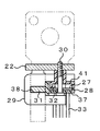
【解決手段】 この電流検出器21は、端子バー22の折曲部31を取り囲むU字形の磁気コア26と、磁気コア26の空隙部36の磁束密度を検出するホール素子が実装されたホール素子基板27と、ホール素子基板27を磁気コア26に対し一定の位置に保持するホルダ28と、磁気コア26の基部39を覆うカバー29と、ホルダ28およびカバー29を端子バー22に共締めするネジ30とを備える。磁気コア26の脚部34をホルダ28の係止溝35に挿入する。ホール素子基板27をホルダ28の定置部37に装着し、ホール素子を磁気コア26の空隙部36に定置する。カバー29に挟持部41を設け、挟着部41と定置部37との間にホール素子基板27を挟持する。
【選択図】 図6
Description
(1)線路導体を取り囲む磁気コアと、磁気コアの空隙部に発生した磁束の密度を検出する磁電変換素子と、磁気コアおよび磁電変換素子を一定の相関位置に保持するホルダと、ホルダを線路導体に組み付ける組付手段とを備えたことを特徴とする電流検出器。
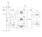
(a)ブレーカ1の線路電流をホール素子32で検出するので、変流器(CT)と比較し、電流検出器21を小型に構成し、ケーシング2内にコンパクトに設置できる。
(b)特に、磁気コア26をU字形に形成したので、電流検出器21が端子バー22の周辺に占めるスペースを縮小し、ケーシング2の小型化を促進できる。
(d)また、ホルダ28を端子バー22に組み付けたので、端子バー22に対する磁気コア26とホール素子32の相関位置を固定し、線路電流をより高精度に検出できる。
(f)ホール素子基板27をホルダ28の定置部37とカバー29の挟持部41とで挟み付けたので、磁気コア26の空隙部36にホール素子32を確実に定置し、電流検出精度を長期間安定させることができる。
(g)ホルダ28とカバー29をネジ30で端子バー22に共締めしたので、電流検出器21の複数の部品を端子バー22に容易に一体化でき、このアセンブリーをブレーカ1のケーシング2に簡単に装着できる。
21 電流検出器
22 端子バー
26 磁気コア
27 ホール素子基板
28 ホルダ
29 カバー
30 ネジ
32 ホール素子
34 脚部
35 係止溝
36 空隙部
37 定置部
39 基部
40 被覆部
41 挟持部
Claims (4)
- ブレーカの線路導体に流れる電流を検出する電流検出器において、線路導体を取り囲む磁気コアと、磁気コアの空隙部に発生した磁束の密度を検出する磁電変換素子と、磁気コアおよび磁電変換素子を一定の相関位置に保持するホルダと、ホルダを線路導体に組み付ける組付手段とを備えたことを特徴とする電流検出器。
- 前記磁気コアをU字形またはC字形に形成し、前記ホルダに磁気コアの一対の脚部を係止する係止部と、磁電変換素子を磁気コアの空隙部に定置する定置部とを設けた請求項1記載の電流検出器。
- 前記磁気コアの基部を覆うカバーを備え、カバーに挟持部を形成し、挟持部と前記定置部との間に磁電変換素子を挟持した請求項2記載の電流検出器。
- 前記組付手段がネジを含み、ネジでホルダとカバーを線路導体に共締めした請求項3記載の電流検出器。
Priority Applications (1)
| Application Number | Priority Date | Filing Date | Title |
|---|---|---|---|
| JP2008244067A JP5150432B2 (ja) | 2008-09-24 | 2008-09-24 | ブレーカの電流検出器 |
Applications Claiming Priority (1)
| Application Number | Priority Date | Filing Date | Title |
|---|---|---|---|
| JP2008244067A JP5150432B2 (ja) | 2008-09-24 | 2008-09-24 | ブレーカの電流検出器 |
Publications (2)
| Publication Number | Publication Date |
|---|---|
| JP2010078347A true JP2010078347A (ja) | 2010-04-08 |
| JP5150432B2 JP5150432B2 (ja) | 2013-02-20 |
Family
ID=42208990
Family Applications (1)
| Application Number | Title | Priority Date | Filing Date |
|---|---|---|---|
| JP2008244067A Active JP5150432B2 (ja) | 2008-09-24 | 2008-09-24 | ブレーカの電流検出器 |
Country Status (1)
| Country | Link |
|---|---|
| JP (1) | JP5150432B2 (ja) |
Cited By (5)
| Publication number | Priority date | Publication date | Assignee | Title |
|---|---|---|---|---|
| JP2013113687A (ja) * | 2011-11-28 | 2013-06-10 | Toyota Industries Corp | 電流検出装置 |
| JP2014026739A (ja) * | 2012-07-24 | 2014-02-06 | Nitto Kogyo Co Ltd | 配電機器 |
| JP2014035322A (ja) * | 2012-08-10 | 2014-02-24 | Tokai Rika Co Ltd | コアホルダ及び電流センサ |
| JP2014235156A (ja) * | 2013-06-05 | 2014-12-15 | 株式会社豊田自動織機 | 電流検出装置 |
| JP2015523847A (ja) * | 2012-07-09 | 2015-08-13 | ソーラーボス、インク. | 太陽電池パネルにおける逆電流障害の防止 |
Citations (3)
| Publication number | Priority date | Publication date | Assignee | Title |
|---|---|---|---|---|
| JPH0451666U (ja) * | 1990-09-05 | 1992-04-30 | ||
| JPH0686080U (ja) * | 1993-05-21 | 1994-12-13 | スタンレー電気株式会社 | 電流検出装置 |
| JPH07280846A (ja) * | 1994-04-15 | 1995-10-27 | Nippon Telegr & Teleph Corp <Ntt> | 電流測定部付きブレーカー |
-
2008
- 2008-09-24 JP JP2008244067A patent/JP5150432B2/ja active Active
Patent Citations (3)
| Publication number | Priority date | Publication date | Assignee | Title |
|---|---|---|---|---|
| JPH0451666U (ja) * | 1990-09-05 | 1992-04-30 | ||
| JPH0686080U (ja) * | 1993-05-21 | 1994-12-13 | スタンレー電気株式会社 | 電流検出装置 |
| JPH07280846A (ja) * | 1994-04-15 | 1995-10-27 | Nippon Telegr & Teleph Corp <Ntt> | 電流測定部付きブレーカー |
Cited By (5)
| Publication number | Priority date | Publication date | Assignee | Title |
|---|---|---|---|---|
| JP2013113687A (ja) * | 2011-11-28 | 2013-06-10 | Toyota Industries Corp | 電流検出装置 |
| JP2015523847A (ja) * | 2012-07-09 | 2015-08-13 | ソーラーボス、インク. | 太陽電池パネルにおける逆電流障害の防止 |
| JP2014026739A (ja) * | 2012-07-24 | 2014-02-06 | Nitto Kogyo Co Ltd | 配電機器 |
| JP2014035322A (ja) * | 2012-08-10 | 2014-02-24 | Tokai Rika Co Ltd | コアホルダ及び電流センサ |
| JP2014235156A (ja) * | 2013-06-05 | 2014-12-15 | 株式会社豊田自動織機 | 電流検出装置 |
Also Published As
| Publication number | Publication date |
|---|---|
| JP5150432B2 (ja) | 2013-02-20 |
Similar Documents
| Publication | Publication Date | Title |
|---|---|---|
| US5943204A (en) | Electronic trip unit with dedicated override current sensor | |
| CN101496245B (zh) | 配电盘 | |
| JP5150432B2 (ja) | ブレーカの電流検出器 | |
| JP4893358B2 (ja) | 漏電遮断器の漏電引外し装置 | |
| TW421811B (en) | Circuit breaker with a power-on information apparatus | |
| US20060290454A1 (en) | Measuring device for measuring differential current, trip module comprising one such measuring device and switchgear unit having one such module | |
| JP2008159456A (ja) | 漏電遮断器 | |
| JP5116582B2 (ja) | 漏電遮断器 | |
| CN1637968B (zh) | 为用在低压断路器中的电子保护装置供电的装置 | |
| JP5731876B2 (ja) | 電流検出装置およびこれを用いた電力量計 | |
| JP2708988B2 (ja) | 電流検出装置 | |
| JP2013161752A (ja) | 回路遮断器 | |
| KR101604279B1 (ko) | 직류 회로차단기용 직류 전류 센서 | |
| JP4012098B2 (ja) | 漏電遮断器 | |
| JP2727738B2 (ja) | 配線用遮断器 | |
| JP5908300B2 (ja) | 回路遮断器 | |
| JP2785415B2 (ja) | 漏電遮断器 | |
| JP5922423B2 (ja) | 回路遮断器 | |
| JP5922426B2 (ja) | 回路遮断器 | |
| JP7561721B2 (ja) | 変流器一体形電流センサおよび遮断器 | |
| US11821923B2 (en) | Arrangement and switching device with contactless current measuring capability | |
| KR20010027246A (ko) | 교류 전류센서 및 이것을 내장하는 전력기기 | |
| JP3375277B2 (ja) | 漏電遮断器 | |
| JP5274958B2 (ja) | 瞬時遮断機構を備えたブレーカ | |
| WO1998042001A1 (en) | Earth leakage circuit breaker |
Legal Events
| Date | Code | Title | Description |
|---|---|---|---|
| A621 | Written request for application examination |
Free format text: JAPANESE INTERMEDIATE CODE: A621 Effective date: 20110829 |
|
| A977 | Report on retrieval |
Free format text: JAPANESE INTERMEDIATE CODE: A971007 Effective date: 20120629 |
|
| A131 | Notification of reasons for refusal |
Free format text: JAPANESE INTERMEDIATE CODE: A131 Effective date: 20120710 |
|
| A521 | Request for written amendment filed |
Free format text: JAPANESE INTERMEDIATE CODE: A523 Effective date: 20120831 |
|
| TRDD | Decision of grant or rejection written | ||
| A01 | Written decision to grant a patent or to grant a registration (utility model) |
Free format text: JAPANESE INTERMEDIATE CODE: A01 Effective date: 20121106 |
|
| A61 | First payment of annual fees (during grant procedure) |
Free format text: JAPANESE INTERMEDIATE CODE: A61 Effective date: 20121203 |
|
| R150 | Certificate of patent or registration of utility model |
Ref document number: 5150432 Country of ref document: JP Free format text: JAPANESE INTERMEDIATE CODE: R150 |
|
| FPAY | Renewal fee payment (event date is renewal date of database) |
Free format text: PAYMENT UNTIL: 20151207 Year of fee payment: 3 |
|
| R250 | Receipt of annual fees |
Free format text: JAPANESE INTERMEDIATE CODE: R250 |
|
| R250 | Receipt of annual fees |
Free format text: JAPANESE INTERMEDIATE CODE: R250 |
|
| R250 | Receipt of annual fees |
Free format text: JAPANESE INTERMEDIATE CODE: R250 |
|
| R250 | Receipt of annual fees |
Free format text: JAPANESE INTERMEDIATE CODE: R250 |
|
| R250 | Receipt of annual fees |
Free format text: JAPANESE INTERMEDIATE CODE: R250 |
|
| R250 | Receipt of annual fees |
Free format text: JAPANESE INTERMEDIATE CODE: R250 |
|
| R250 | Receipt of annual fees |
Free format text: JAPANESE INTERMEDIATE CODE: R250 |