JP2010077670A - Apparatus for feeding soil improving material - Google Patents
Apparatus for feeding soil improving material Download PDFInfo
- Publication number
- JP2010077670A JP2010077670A JP2008246694A JP2008246694A JP2010077670A JP 2010077670 A JP2010077670 A JP 2010077670A JP 2008246694 A JP2008246694 A JP 2008246694A JP 2008246694 A JP2008246694 A JP 2008246694A JP 2010077670 A JP2010077670 A JP 2010077670A
- Authority
- JP
- Japan
- Prior art keywords
- feeder
- speed
- storage tank
- soil
- driving
- Prior art date
- Legal status (The legal status is an assumption and is not a legal conclusion. Google has not performed a legal analysis and makes no representation as to the accuracy of the status listed.)
- Granted
Links
Images


Classifications
-
- A—HUMAN NECESSITIES
- A01—AGRICULTURE; FORESTRY; ANIMAL HUSBANDRY; HUNTING; TRAPPING; FISHING
- A01C—PLANTING; SOWING; FERTILISING
- A01C15/00—Fertiliser distributors
- A01C15/06—Fertiliser distributors with distributing slots, e.g. adjustable openings for dosing
- A01C15/08—Fertiliser distributors with distributing slots, e.g. adjustable openings for dosing with pushers or stirrers in the slots
-
- G—PHYSICS
- G05—CONTROLLING; REGULATING
- G05D—SYSTEMS FOR CONTROLLING OR REGULATING NON-ELECTRIC VARIABLES
- G05D11/00—Control of flow ratio
- G05D11/02—Controlling ratio of two or more flows of fluid or fluent material
- G05D11/13—Controlling ratio of two or more flows of fluid or fluent material characterised by the use of electric means
- G05D11/135—Controlling ratio of two or more flows of fluid or fluent material characterised by the use of electric means by sensing at least one property of the mixture
- G05D11/136—Controlling ratio of two or more flows of fluid or fluent material characterised by the use of electric means by sensing at least one property of the mixture by sensing the viscosity
-
- A—HUMAN NECESSITIES
- A01—AGRICULTURE; FORESTRY; ANIMAL HUSBANDRY; HUNTING; TRAPPING; FISHING
- A01C—PLANTING; SOWING; FERTILISING
- A01C15/00—Fertiliser distributors
Landscapes
- Life Sciences & Earth Sciences (AREA)
- Physics & Mathematics (AREA)
- General Physics & Mathematics (AREA)
- Engineering & Computer Science (AREA)
- Automation & Control Theory (AREA)
- Soil Sciences (AREA)
- Environmental Sciences (AREA)
- Mixers Of The Rotary Stirring Type (AREA)
- Accessories For Mixers (AREA)
- Feeding, Discharge, Calcimining, Fusing, And Gas-Generation Devices (AREA)
Abstract
Description
本発明は土質改良材を土砂に供給する土質改良材供給装置に関する。 The present invention relates to a soil improvement material supply device for supplying a soil improvement material to earth and sand.
粉体供給装置としては、貯留タンク内に貯留した粉体を下部のフィーダによって貯留タンク外部に排出するものが一般的である(特許文献1等参照)。フィーダとしては、スクリュフィーダの他にも、ロータリフィーダ(ロータリバルブ)やベルトコンベヤ、テーブルフィーダ等、様々なものが用いられ得る。
As a powder supply device, a device that discharges powder stored in a storage tank to the outside of the storage tank by a lower feeder is generally used (see
土質改良機は、一般に粉体供給装置である土質改良材供給装置によって粉粒状の石灰等の土質改良材を改質対象土砂に供給し、土砂を土質改良材と混合処理して改良土を生成する。貯留タンクへの土質改良材の充填は、代表的にはサイロを用いて行う場合とフレキシブルコンテナを用いて行う場合があるが、いずれにしても貯留タンクの上部から土質改良材を充填するので土質改良材には落下時に空気が混入する。したがって、このときの空気の混入度合いによって貯留タンク内の土質改良材の嵩密度は変動し、空気混入量が多いほど嵩密度が小さくなる。 A soil conditioner is generally a powder feeder, which supplies a soil conditioner such as pulverized lime to the soil to be reformed using a soil conditioner feeder, and mixes the soil with the soil conditioner to produce improved soil. To do. The storage tank is typically filled with a soil improvement material using a silo or a flexible container, but in any case the soil improvement material is filled from the top of the storage tank. The improved material is mixed with air when dropped. Therefore, the bulk density of the soil quality improving material in the storage tank varies depending on the degree of air mixing at this time, and the bulk density decreases as the amount of air mixing increases.
ここで、土質改良作業では改質対象土砂に対して目標重量の土質改良材を添加し、土砂に対する土質改良材の混合比(改良土品質)を安定に確保することが重要である。土質改良材の供給量制御には、フィーダに取り込まれる土質改良材の量を制御する方法、及びフィーダの駆動速度を制御する方法があるが、後者の方が精度面で優位であり一般的である。また、土質改良材供給装置によって改質対象土砂に土質改良材を直接供給する場合、土質改良材の供給重量自体を計測することは容易ではない。そこで、一般にはフィーダの駆動速度から土質改良材の供給体積を推定し、それに土質改良材の嵩密度を乗じることで供給重量を管理することが行われる。 Here, in the soil improvement work, it is important to add a target weight soil improvement material to the soil to be improved and to ensure a stable mixing ratio (improvement soil quality) of the soil improvement material to the soil. There are two methods for controlling the amount of soil improvement material supplied: a method for controlling the amount of soil improvement material taken into the feeder and a method for controlling the drive speed of the feeder. is there. In addition, when the soil improvement material is directly supplied to the soil to be reformed by the soil improvement material supply device, it is not easy to measure the supply weight of the soil improvement material itself. In general, therefore, the supply volume of the soil improvement material is estimated from the driving speed of the feeder, and the supply weight is managed by multiplying the volume by the bulk density of the soil improvement material.
したがって、空気の混入によって嵩密度が変動すると実際にはフィーダの駆動速度に対する土質改良材の供給重量が変動するが、上記の計算方法では一般に嵩密度を一定値と想定して土質改良材の供給重量を算出するので嵩密度が変動しても演算結果に反映されない。嵩密度によっては土質改良材の供給量の演算結果と実際の値との誤差が大きくなり、土質改良材の供給精度、改良土品質の信頼性にも影響し得る。 Therefore, if the bulk density fluctuates due to air mixing, the supply weight of the soil improvement material will actually fluctuate with respect to the driving speed of the feeder, but the above calculation method generally assumes that the bulk density is a constant value and supplies the soil improvement material. Since the weight is calculated, even if the bulk density fluctuates, it is not reflected in the calculation result. Depending on the bulk density, the error between the calculation result of the supply amount of the soil improvement material and the actual value becomes large, which may affect the supply accuracy of the soil improvement material and the reliability of the improved soil quality.
そこで本発明は、土質改良材の嵩密度の変動による影響を抑制し供給精度を向上させることを目的とする。 Therefore, an object of the present invention is to suppress the influence due to the fluctuation of the bulk density of the soil improvement material and improve the supply accuracy.
(1)上記目的を達成するために、本発明は、土質改良材を土砂に供給する土質改良材供給装置において、土質改良材を貯留する貯留タンクと、前記貯留タンクの下部に設けられ前記貯留タンク内の土質改良材を土砂に供給するフィーダと、前記貯留タンクに設けられ前記貯留タンク内の土質改良材を撹拌する撹拌装置と、前記フィーダの駆動負荷を検出する負荷検出器と、前記フィーダ及び前記撹拌装置を制御する制御装置とを備え、前記制御装置は、前記負荷検出器からの信号を入力する入力部と、前記フィーダの駆動負荷及び前記撹拌装置の駆動速度の対応関係を記憶した記憶部と、前記負荷検出器からの信号及び前記記憶部の記憶情報を基に、前記フィーダの駆動負荷の低下に伴って前記撹拌装置への速度指令値を増大させ、前記フィーダの駆動負荷の上昇に伴って前記撹拌装置への速度指令値を減少させる指令部と、前記指令部で生成された指令値を前記撹拌装置に出力する出力部とを備えたことを特徴とする。 (1) In order to achieve the above object, the present invention provides a soil improvement material supply device that supplies soil improvement material to earth and sand, a storage tank that stores the soil improvement material, and a storage tank that is provided below the storage tank. A feeder for supplying soil improvement material in the tank to the soil, a stirring device provided in the storage tank for stirring the soil improvement material in the storage tank, a load detector for detecting a driving load of the feeder, and the feeder And a control device for controlling the agitation device, wherein the control device stores a correspondence relationship between an input unit for inputting a signal from the load detector, a driving load of the feeder and a driving speed of the agitation device. Based on the storage unit, the signal from the load detector and the storage information of the storage unit, the speed command value to the agitator is increased as the driving load of the feeder decreases, and the A command unit that decreases a speed command value to the stirring device as the driving load of the motor increases, and an output unit that outputs the command value generated by the command unit to the stirring device. And
(2)上記目的を達成するために、また本発明は、土質改良材を土砂に供給する土質改良材供給装置において、土質改良材を貯留する貯留タンクと、前記貯留タンクの下部に設けられ前記貯留タンク内の土質改良材を土砂に供給するフィーダと、前記貯留タンクに設けられ前記貯留タンク内の土質改良材を撹拌する撹拌装置と、前記フィーダ及び前記撹拌装置を制御する制御装置と、前記フィーダの駆動速度を操作する操作装置とを備え、前記制御装置は、前記フィーダ及び前記撹拌装置の駆動速度の指令値の対応関係を記憶した記憶部と、前記操作装置からの信号及び前記記憶部の記憶情報を基に、前記フィーダへの速度指令値の増大に伴って前記撹拌装置への速度指令値を増大させ、前記フィーダへの速度指令値の減少に伴って前記撹拌装置への速度指令値を減少させる指令部と、前記指令部で生成された指令値を前記フィーダ及び前記撹拌装置に出力する出力部とを備えたことを特徴とする。 (2) In order to achieve the above object, the present invention also provides a soil improvement material supply device for supplying a soil quality improvement material to earth and sand, a storage tank for storing the soil quality improvement material, and a lower part of the storage tank. A feeder for supplying soil improvement material in the storage tank to the soil, a stirring device provided in the storage tank for stirring the soil improvement material in the storage tank, a control device for controlling the feeder and the stirring device, An operation device that operates the driving speed of the feeder, and the control device stores a correspondence relationship between command values of the driving speed of the feeder and the stirring device, a signal from the operation device, and the storage portion Based on the stored information, the speed command value to the stirring device is increased as the speed command value to the feeder increases, and the stirring is performed as the speed command value to the feeder decreases. A command unit for reducing the speed command value for the location, characterized in that the command value generated in the command section and an output section for outputting to the feeder and the stirring device.
(3)上記(2)において、好ましくは、前記フィーダの駆動負荷を検出する負荷検出器をさらに備え、前記記憶部は、前記フィーダの駆動負荷の複数の範囲毎に前記フィーダ及び前記撹拌装置の駆動速度の対応関係を記憶しており、前記指令部は、前記負荷検出器からの信号に応じた前記対応関係を参照し前記撹拌装置への速度指令値を生成することを特徴とする。 (3) In the above (2), preferably, it further includes a load detector for detecting a driving load of the feeder, and the storage unit is configured to store the feeder and the stirring device for each of a plurality of ranges of the driving load of the feeder. The correspondence relationship of drive speed is memorize | stored, The said instruction | command part produces | generates the speed command value to the said stirring apparatus with reference to the said correspondence according to the signal from the said load detector.
(4)上記(1)又は(3)において、好ましくは、前記記憶部は、前記フィーダの駆動負荷に対して予め設定した閾値を記憶しており、前記指令部は、前記負荷検出器からの信号を基に演算した前記フィーダの駆動負荷が前記閾値に達したら前記撹拌装置への速度指令値をゼロにすることを特徴とする。 (4) In the above (1) or (3), preferably, the storage unit stores a threshold value set in advance for the driving load of the feeder, and the command unit receives from the load detector. When the feeder driving load calculated based on the signal reaches the threshold value, the speed command value to the stirring device is set to zero.
(5)上記目的を達成するために、また本発明は、土質改良材を土砂に供給する土質改良材供給装置において、土質改良材を貯留する貯留タンクと、前記貯留タンクの下部に設けられ前記貯留タンク内の土質改良材を土砂に供給するフィーダと、前記貯留タンクに設けられ前記貯留タンク内の土質改良材を撹拌する撹拌装置と、前記フィーダの駆動速度を検出する速度検出器と、前記フィーダ及び前記撹拌装置を制御する制御装置とを備え、前記制御装置は、前記速度検出器からの信号を入力する入力部と、前記フィーダの駆動速度及び前記撹拌装置の駆動速度の対応関係を記憶した記憶部と、前記速度検出器からの信号及び前記記憶部の記憶情報を基に、前記フィーダの駆動速度の上昇に伴って前記撹拌装置への速度指令値を上昇させ、前記フィーダの駆動速度の低下に伴って前記撹拌装置への速度指令値を低下させる指令部と、前記指令部で生成された指令値を前記撹拌装置に出力する出力部とを備えたことを特徴とする。 (5) In order to achieve the above object, the present invention provides a soil improvement material supply device for supplying a soil quality improvement material to earth and sand, a storage tank for storing the soil quality improvement material, and a lower part of the storage tank. A feeder for supplying the soil improvement material in the storage tank to the soil, a stirring device provided in the storage tank for stirring the soil improvement material in the storage tank, a speed detector for detecting the driving speed of the feeder, A control device that controls the feeder and the stirring device, and the control device stores a correspondence relationship between an input unit that inputs a signal from the speed detector, a driving speed of the feeder, and a driving speed of the stirring device. The speed command value to the stirring device is increased with the increase in the driving speed of the feeder, based on the storage section, the signal from the speed detector, and the storage information in the storage section. A command unit that reduces a speed command value to the stirring device in accordance with a decrease in the driving speed of the feeder, and an output unit that outputs the command value generated by the command unit to the stirring device. To do.
(6)上記目的を達成するために、また本発明は、土質改良材を土砂に供給する土質改良材供給装置において、土質改良材を貯留する貯留タンクと、前記貯留タンクの下部に設けられ前記貯留タンク内の土質改良材を土砂に供給するフィーダと、前記貯留タンクに設けられ前記貯留タンク内の土質改良材を撹拌する撹拌装置と、前記フィーダの駆動負荷を検出する負荷検出器と、前記フィーダ及び前記撹拌装置を制御する制御装置とを備え、前記制御装置は、前記負荷検出器からの信号を入力する入力部と、フィーダの駆動負荷に対して予め設定した閾値を記憶した記憶部と、前記負荷検出器からの信号を基に演算した前記フィーダの駆動負荷が前記閾値より低い場合、前記撹拌装置への一定の大きさの速度指令値を生成し、前記フィーダの駆動負荷が前記閾値以上の場合、前記撹拌装置への速度指令値をゼロにする指令部と、前記指令部で生成された指令値を前記撹拌装置に出力する出力部とを備えたことを特徴とする。 (6) In order to achieve the above object, the present invention also provides a soil improvement material supply device for supplying a soil quality improvement material to earth and sand, a storage tank for storing the soil quality improvement material, and a lower part of the storage tank. A feeder for supplying the soil improvement material in the storage tank to the soil, a stirring device provided in the storage tank for stirring the soil improvement material in the storage tank, a load detector for detecting a driving load of the feeder, A control unit that controls the feeder and the stirring device, the control unit including an input unit that inputs a signal from the load detector, and a storage unit that stores a preset threshold for the driving load of the feeder; When the feeder driving load calculated based on the signal from the load detector is lower than the threshold value, a constant speed command value to the stirring device is generated, and the feeder When the dynamic load is equal to or greater than the threshold, the apparatus includes a command unit that sets a speed command value to the stirring device to zero, and an output unit that outputs the command value generated by the command unit to the stirring device. And
(7)上記(1)−(6)のいずれかにおいて、好ましくは、前記フィーダは、前記貯留タンクの下部に連設された筒状のケーシング、及び前記ケーシング内に通された回転軸及び前記回転軸の外周部に設けられたスクリュを有するスクリュフィーダであることを特徴とする。 (7) In any one of the above (1) to (6), preferably, the feeder includes a cylindrical casing connected to a lower part of the storage tank, a rotating shaft passed through the casing, and the It is a screw feeder which has a screw provided in the outer peripheral part of the rotating shaft.
本発明によれば、アーチブレーカによって適正な駆動速度で撹拌することによって貯留タンク内の土質改良材の嵩密度を安定化させるので、土質改良材の嵩密度の変動による影響を抑制し供給精度を向上させることができる。 According to the present invention, the bulk density of the soil conditioner in the storage tank is stabilized by stirring at an appropriate driving speed by the arch breaker, so that the influence of fluctuations in the bulk density of the soil conditioner is suppressed and the supply accuracy is reduced. Can be improved.
以下に図面を用いて本発明の実施の形態を説明する。 Embodiments of the present invention will be described below with reference to the drawings.
図1は本発明の第1の実施の形態に係る土質改良材供給装置を備えた自走式土質改良機の全体構造を表す側面図、図2はその平面図である。以下の説明において特に断りのない場合、図1及び図2中の左側を一方側、右側を他方側とする。 FIG. 1 is a side view showing the entire structure of a self-propelled soil conditioner equipped with a soil conditioner supply apparatus according to a first embodiment of the present invention, and FIG. 2 is a plan view thereof. In the following description, the left side in FIGS. 1 and 2 is one side and the right side is the other side unless otherwise specified.
これら図1及び図2に示した自走式土質改良機は、自力走行するための走行体1、改質対象土砂を受け入れるためのホッパ12、ホッパ12に受け入れられた土砂を搬送する搬送コンベヤ13、土砂に土質改良材を供給する土質改良材供給装置14、土砂と土質改良材を混合処理する混合装置19、混合装置19から排出された改良土を搬送し機外に排出する排出コンベヤ26、及び各搭載機器の動力源等を内蔵した動力装置21を備えている。
The self-propelled soil improvement machine shown in FIGS. 1 and 2 includes a traveling
走行体1は、左右一対の走行装置2、及び走行装置2の上部にほぼ平行に延設した一対の本体フレーム3で構成されている。走行装置2は、本体フレーム3の下部に連設したトラックフレーム4、トラックフレーム4の両端にそれぞれ設けた従動輪(アイドラ)5及び駆動輪6、従動輪5及び駆動輪6に掛け回した履帯(無限軌道履帯)7、及び駆動輪6に直結した走行用の駆動装置8を備えている。本体フレーム3上には支持ポスト9a,9bが立設されており、これら支持ポスト9a,9bによって、本体フレーム3の長手方向の一方側の上方に配置した支持フレーム10及び本体フレーム3の長手方向のほぼ中央部の上方に配置した支持フレーム11が支持されている。
The
ホッパ12は、上下が開口した枠型の部材であって上方に向かって拡開するように形成されている。このホッパ12は、支持フレーム10を介して本体フレーム3の長手方向一方側に支持されている。搬送コンベヤ13は、ホッパ12の下方から後述する混合装置19の入口(図示せず)の上方にかけてほぼ水平に延在するように上記支持ポスト9a等によって支持されている。
The
土質改良材供給装置14は、土質改良材を貯留する貯留タンク15、及び貯留タンク15内の土質改良材を土砂に供給するスクリュフィーダ16を備えており、上記支持フレーム11を介し本体フレーム3のほぼ中央部上に配設されている。機体幅方向の片側(図2中上側)には、この土質改良材供給装置14の側方に位置するようにクレーン18(図2参照)が配設されている。このクレーン18は、土質改良材を充填した例えばフレキシブルコンテナ(トンパック)等を貯留タンク15の上方に吊るし、フレキシブルコンテナ内の土質改良材の貯留タンク15への充填を補助するのに用いられる。
The soil improvement
混合装置19は、搬送コンベヤ13から導入された土砂及び土質改良材をパドルミキサ(図示せず)によって混合し改良土を生成するものであって、スクリュフィーダ16の下方に位置するように本体フレーム3の長手方向ほぼ中央上に設けられている。搬送コンベヤ13の放出端(図1中右側端部)からこの混合装置19の土砂及び土質改良材の入口(図示せず)にかけての空間はカバー20で包囲されている。このカバー20で包囲された空間には上記スクリュフィーダ16の土質改良材の排出口64も臨んでおり、混合装置18の入口に投入される際の土砂及び土質改良材の飛散抑制に配慮されている。
The
動力装置21は、本体フレーム3の長手方向他方側の端部に支持部材22を介して支持されている。この動力装置21の前方側(図1及び図2中左側)の区画には運転席23が設けられている。この運転席23には、走行装置2を操作する操作レバー24等が備えられている。また、機体側面の運転席23の下方位置には、走行装置2を除く混合装置19等の各機器を操作する操作盤25が設けられている。
The
排出コンベヤ26は、混合装置19の下方から本体フレーム3の長手方向他方側に向かって所定距離ほぼ水平に延在した後、動力装置21の下方付近から上り傾斜に延在しており、図示しない駆動プーリに連結した駆動装置27(図2参照)によって搬送ベルトを循環駆動させて搬送ベルト上の改良土を搬出する。排出コンベヤ26の上流部分(図1中の左側部分)は図示しない支持部材を介して本体フレーム3に、中間部及び下流側部分(図1中の右側部分)は支持部材29,30を介して動力装置21後方(図1中右側)に設けたアーム28に、それぞれ吊り下げ支持されている。
The
図3は前述した土質改良材供給装置14を抽出して表す側断面図で、本体フレーム3の長手方向に沿った鉛直断面を表している。
FIG. 3 is a side cross-sectional view showing the above-described soil improvement
図3において、貯留タンク15は、上記支持フレーム11上に固定したフレーム41と、フレーム41上に固定され中央が開口した底板42と、この底板42上に連設した水平断面が方形状(円形状でも良い)の蛇腹部43と、この蛇腹部43の上部開口を塞ぐ天板44と、蛇腹部43の下部に連設し下方に向かって縮径するシュート17とを備えている。蛇腹部43は、伸縮自在なフレキシブルな材料、例えばポリエチレン系ゴム材料で構成されており、内部に貯留した土質改良材からの内圧が下方ほど高くなるため、図3に示すように補強リング45のピッチを下方ほど狭くしてある。天板44の中央には土質改良材の受入口47が設けられており、天板44の上面には受入口47を開閉する開閉蓋46が蝶番(図示せず)を介して取付けられている。
In FIG. 3, the
天板44の受入口47の下方位置にはカッタ48が装着されている。このカッタ48は開閉蓋46の下面に支持アーム49を介して垂設された枠体50上に尖頭部を上方に向けた状態で取り付けられている。枠体50の配置は天板44から所定深さだけ低く、カッタ48の頂部は開閉蓋46よりも下側に位置しており、開閉蓋46を閉じるとカッタ48が完全に貯留タンク15内に収容される。貯留タンク15にフレキシブルコンテナ(トンパック)を用いて土質改良材を充填するときには、天板44に設けた開閉蓋46を開き、フレキシブルコンテナをクレーン18で受入口47に挿入し、フレキシブルコンテナを自重でカッタ48に押し付ける。これによって、フレキシブルコンテナの下端部が切り裂かれ、フレキシブルコンテナ内部の土質改良材が貯留タンク15内に流入する。また、フレキシブルコンテナを用いず、自走式土質改良機とは別に設けたサイロからホースを介して貯留タンク15に土質改良材を充填する場合もある。この場合も貯留タンク15へは天板44側から土質改良材が充填される。
A
上記シュート17は、下方に向かって縮径する四角錐状(円錐状としても良い)の部材であり、上下が開口している。シュート17の上部開口54は、蛇腹部43の下端部に連結され、蛇腹部43とシュート17の内部空間が通じている。一方、シュート17の下部開口55はスクリュフィーダ16に連結され、シュート17とスクリュフィーダ16の内部空間が通じている。これにより、貯留タンク15に充填された土質改良材は、上部開口54を介してシュート17に流入し、シュート17にガイドされて下部開口55からスクリュフィーダ16に導入される。このとき、シュート17の下部開口55は、スクリュフィーダ16の軸線に直交する方向にとった幅寸法(図3中の紙面に直交する方向)に対して上記スクリュフィーダ16の軸線方向(図2中の左右方向)にとった長さ寸法が長く形成されている。また、この四角錐状のシュート17の上部開口54から下部開口55に向かって延びる内壁面のコーナー部分(各側壁の境界部分)は、いわゆるR材を張ったり溶接ビードを形成したりしてR状に形成されており、シュート17の内面のコーナー部分に土質改良材が滞留し難いように配慮されている。シュート17の内壁面には、スクリュフィーダ16のケーシング61の内周面と併せてゴムライニング等を施すこともできる。
The
シュート17の内部には、貯留タンク15内の土質改良材を撹拌するアーチブレーカ(撹拌装置)51が設けられている。このアーチブレーカ51は、シュート17に対して回転自在に支持された回転軸52と、この回転軸52に対して所定のピッチで設けられた複数の攪拌棒53と、回転軸52の端部(図3中右端)に直結した駆動装置56とで構成されている。
Inside the
本実施の形態では、回転軸52は本体フレーム3の長手方向に沿って水平に配置されている。各撹拌棒53は下方のスクリュフィーダ16の傾斜に合わせて図3中の左側のものほど短くなっており、下部開口55を介して臨むスクリュ62に各撹拌棒53の先端の回転軌跡を近接させてある。撹拌棒53はまた、回転軸52の軸方向から見て回転軸52の外周部に180度ピッチで設けられており、図3に示した状態から90度回転すると撹拌棒53は全て水平方向を向く。詳細には図示していないが、アーチブレーカ51には、撹拌棒53が水平姿勢となる回転軸52の角度位置を検出するセンサが設けられており、駆動停止時には撹拌棒53が水平を向いた姿勢で停止するように制御される。駆動装置56は油圧モータ(電動でも良い)であってシュート17の外壁部に設けられている。
In the present embodiment, the
この駆動装置56によってアーチブレーカ51が回転駆動されると、シュート17内の土質改良材が攪拌棒53によって攪拌され、シュート17内の架橋の発生が抑制され、また土質改良材の塊がある場合にはその解砕も促進される。さらには、下部開口55近傍の土質改良材をスクリュフィーダ16に送り込む機能も果たし得る。
When the
また、図3では図示省略しているが、天板44の外周部には複数(この例では4つ)の取り付け部が設けられている。これら取り付け部の下部には、図1に示したように支柱が固定的に垂設されている。各支柱は、上記シュート17の底板42に取り付けたガイド筒に上下にスライド可能に通されている。このとき、各支柱にはそれぞれ上下のピン穴が穿設されており、ガイド筒に穿設されたピン穴に上下いずれかのピン穴の位置を合わせてストッパピンを差し込むことによって支柱がガイド筒に固定される。例えば稼動時等には支柱を引き上げて下側のピン穴をストッパピンでガイド筒に固定することによって貯留タンクの内部容積が確保される。一方、例えば自走式土質改良機をトレーラ等で輸送する時には蛇腹部43を縮めて上側のピン穴をストッパピンでガイド筒に固定することにより、貯留タンク15の高さを低くすることができる。先述したアーチブレーカ51は停止時には撹拌棒53が水平を向くように設定してあるので、蛇腹部43を縮めたときにカッタ48を支持する枠体50をアーチブレーカ51の回転軸52の近くまで下げることができ、貯留タンク15の格納姿勢のコンパクト化にも貢献する。
Although not shown in FIG. 3, a plurality (four in this example) of mounting portions are provided on the outer peripheral portion of the
スクリュフィーダ16は、シュート17の下部に連設した円筒状のケーシング61、ケーシング61内に通され回転自在に支持された回転軸66、回転軸66の外周部に設けられたスクリュ62、及びスクリュ62を回転駆動する油圧モータ(電動モータでも良い)である駆動装置63(図3参照)を備えている。
The
ケーシング61の周胴部の上半側には、図5に示したようにシュート17の下部開口55に連接する土質改良材受入口が開口している。この土質改良材受入口は下部開口55と実質同形に形成されており、その周縁部がシュート17の下部開口55の周縁部に対して溶接等によって接合されている。これによってケーシング61はシュート17の下部に固定されている。また、ケーシング61は支持部材68(図3参照)を介してケーシング61の土質改良材の移送方向下流側(図5中の左側)をシュート17の外壁面に固定することにより、より安定に支持されている。また、ケーシング61の土質改良材の移送方向下流側の端部下側には、土質改良材を排出する土質改良材排出口64が形成されている。
On the upper half side of the peripheral body portion of the casing 61, as shown in FIG. 5, a soil improvement material receiving port connected to the
ケーシング61は、図1に示したように、その土質改良材の移送方向の上流側(図1中の右側)が搬送コンベヤ13と同程度の高さに配置され、そこから土質改良材の移送方向下流側(図1中の左側)に向かって上る方向に傾斜し、下流側端部が搬送コンベヤ13の搬送方向下流側端部(図1中の右端)の上方に位置している。このようにケーシング61を傾斜させ、混合装置19の上方のスペースを利用してその上流側部分を下げることにより、ケーシング61の重心を下げ土質改良材供給装置14の全高が低くなるように配慮されている。さらに、ケーシング61が土質改良材移送方向の下流側に向かって上向きに傾斜しているので、スクリュ62の回転と無関係に土質改良材が流動することに対する抵抗にもなっている。
As shown in FIG. 1, the casing 61 has an upstream side (right side in FIG. 1) in the transfer direction of the soil improvement material arranged at the same height as the transport conveyor 13, and transfers the soil improvement material therefrom. It inclines in the direction going up toward the downstream side in the direction (left side in FIG. 1), and the downstream end is located above the downstream end in the transport direction of the transport conveyor 13 (right end in FIG. 1). In this way, the casing 61 is inclined, and the upstream portion of the mixing
ケーシング61の軸方向の両端は、図3に示したように、スクリュ62の回転軸66を貫通させたエンドプレート65によって塞がれている。エンドプレート65を貫通した回転軸66は、エンドプレート65の外面に取り付けられた軸受67により回転自在に支持されている。スクリュ62の回転軸66は、中空のパイプで形成することによって軽量化することができるが、中実の丸棒材又は角棒材を用いることもできる。
As shown in FIG. 3, both ends of the casing 61 in the axial direction are closed by
スクリュ62は、図5に示した通り、回転軸66の外周につる巻き状に設けた螺旋状の羽根であり、シュート17の下部開口55の全体からケーシング61内に土質改良材が取り込まれるように、シュート17の下部開口55に臨む範囲で土質改良材の移送方向の下流側部分を所定の大きさのピッチとし上流側部分のピッチはこれよりも小さくしてある。スクリュ62のピッチは、下流側に行くにつれて連続的に大きくすることもできるが、本実施の形態では下流側に向けて段階的に大きくなるようにしてある。
As shown in FIG. 5, the
スクリュフィーダ16の駆動装置63は、シュート17の本体フレーム3の長手方向の他方側に、駆動伝達機構(図示せず)を収容した駆動伝達部70(図3参照)を介して取り付けられている。駆動伝達部70は、特に図示していないが、駆動装置63の出力軸、この出力軸に設けたスプロケット(又はプーリ)、スクリュ62の回転軸66の他端(図3中右端)に設けたスプロケット(又はプーリ)、及びこれらスプロケット(又はプーリ)に掛け回したチェーン(又はベルト)を収容している。つまり、スクリュフィーダ16は、駆動伝達部70によりチェーン(又はベルト)を介して駆動装置63の駆動力を回転軸66に伝達しスクリュ62を回転させるようになっている。なお、駆動装置63には、回転速度が可変で制御可能なものを用いることが好ましい。例えば駆動装置63を油圧モータとした場合には、回転数検出器で駆動装置63の回転数を検出し、その検出値と目標回転数との差を基に、制御弁装置によって駆動装置63への圧油の供給流量を調整する構成とすれば、駆動装置63の回転速度すなわち土質改良材の時間当たりの供給量を目標値に近付けることができる。
The
上記構成により、スクリュフィーダ16は、シュート17を介して貯留タンク15から導入された土質改良材を図1中左方向(搬送コンベヤ13の搬送方向と反対方向)に移送し、搬送コンベヤ13の土砂搬送方向の下流側端部(図1中右端部)付近を搬送される土砂に添加する機能を果たす。
With the above configuration, the
図4はフィーダ16及びアーチブレーカ51の油圧駆動回路図である。図4において既出図面と同様の部分には既出図面と同符号を付して説明を省略する。
FIG. 4 is a hydraulic drive circuit diagram of the
図4に示すように、図示しないエンジンにより駆動される油圧ポンプ80と、油圧ポンプ80からフィーダ用の駆動装置63への圧油の流れを制御する制御弁81と、油圧ポンプ80からアーチブレーカ用の駆動装置56への圧油の流れを制御する制御弁82とを備えている。制御弁81,82はパイロット作動形の比例電磁式の3位置切り換え弁であり、それぞれ中立位置81a,82aのとき油圧ポンプ80から駆動装置63,56への圧油の流れを遮断し、油圧ポンプ80の吐出する圧油をタンク83に戻す。そして、ソレノイド駆動部81d,82d(又はソレノイド駆動部81e,82e、以下の対応関係同様)に指令信号が入力されて切換位置81b,82b(又は切換位置81c,82c)に切り換わると、油圧ポンプ80からの圧油が供給管路84a,85a(又は供給管路84b,85b)に導かれ、駆動装置63,56が正転(又は逆転)方向に駆動する。
As shown in FIG. 4, a
また、駆動装置63,56にはフィーダ16及びアーチブレーカ51の駆動速度として駆動装置63,56の回転数をそれぞれ検出する回転数検出器86,87が、フィーダ用駆動装置63への正転駆動用の供給管路84aにはフィーダ16の負荷として供給管路84aの圧油の圧力を検出する負荷検出器88が設けられている。これら検出器86−88の検出信号は、フィーダ16及びアーチブレーカ51を含めた各作動機器の動作を制御する制御装置90(図5参照)に出力される。
The
図5は制御装置90の要部を抽出して表す機能ブロック図である。図5において既出図面と同様の部分には既出図面と同符号を付して説明を省略する。
FIG. 5 is a functional block diagram showing the main part of the
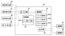
図5に示すように、制御装置90は、操作レバー24や図示しない操作盤を含む操作装置89、また速度検出器86,87及び負荷検出器88からの信号を入力しデジタル信号化する入力部91と、制御手順のプログラムや制御に必要な定数、また演算結果等を格納する記憶部92と、各種演算処理を実行する演算部93と、演算部93で演算・生成された信号をアナログ信号化して上記制御弁81,82を含む各作動機器や表示装置に出力する出力部94とを備えている。
As shown in FIG. 5, the
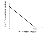
記憶部92は、フィーダ16の駆動負荷及びアーチブレーカ51の駆動速度の対応関係(制御線)を記憶したフィーダ負荷−ブレーカ速度記憶部92aを備えている。フィーダ負荷−ブレーカ速度記憶部92aに記憶された制御線の幾つかの例を図6−図9に示す。
The
図6に示した制御線は、負荷検出器88により検出されたフィーダ16の駆動負荷が0(ゼロ)から増大するのに伴って連続的かつ線形にアーチブレーカ51の駆動速度を減じるもので、フィーダ圧力が最大値Pmaxに到達したところでアーチブレーカ51が停止する。最大値Pmaxは例えば図示しないリリーフ弁により規制された供給管路88の圧力の最大値である。
The control line shown in FIG. 6 decreases the driving speed of the
図7に示した制御線は、図6と同じように負荷検出器88により検出されたフィーダ16の駆動負荷が0(ゼロ)から増大するのに伴ってアーチブレーカ51の駆動速度を減じるものであるが、フィーダ圧力が最大値Pmaxに到達する前に閾値P1(<Pmax)に達した時点でアーチブレーカ51を停止させる。この場合、閾値P1に到達するまではフィーダ16の駆動負荷の増大に伴って連続的かつ線形にアーチブレーカ51を減速してフィーダ16の駆動負荷が閾値P1に達したところで停止させる。フィーダ16の駆動負荷が閾値P1を超えた状態ではアーチブレーカ51は常時停止状態である。
The control line shown in FIG. 7 decreases the driving speed of the
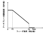
図8に示した制御線では、負荷検出器88により検出されたフィーダ16の駆動負荷が閾値P2(>0)から閾値P3(P2<P3<Pmax)まで増大する間はフィーダ16の駆動負荷の増大に伴ってアーチブレーカ51の駆動速度を線形にかつ連続的に減じている。この制御線では、フィーダ16の駆動負荷が閾値P3に到達した時点ではアーチブレーカ51の駆動速度はまだ0(ゼロ)ではなく一定の大きさを持っているが、フィーダ16の駆動負荷が閾値P3より大きい場合にはアーチブレーカ51は常時停止状態となる。すなわち、フィーダ16の駆動負荷が閾値P3を跨いで変化する場合にはアーチブレーカ51の速度が不連続に変化する。フィーダ16の駆動負荷が閾値P2以下の値で推移している間は所定の速度で駆動する。
In the control line shown in FIG. 8, while the driving load of the
図9に示した制御線では、負荷検出器88により検出されたフィーダ16の駆動負荷が閾値P4(>0)以下の値で推移している間はアーチブレーカ51が設定の速度で駆動し、P4を超えたら停止する。このように、アーチブレーカ51の駆動速度は必ずしも線形に制御する必要はなく、フィーダ16の駆動負荷がある値よりも低いときにアーチブレーカ51を駆動し高いときに停止するといった、ON/OFF制御とすることもできる。また、この例ではアーチブレーカ51の駆動速度が単一の値である単純なON/OFF制御を例示しているが、例えば閾値を複数用意しておき、フィーダ16の駆動負荷の増大に伴ってアーチブレーカ51の駆動速度を段階的(ステップ状)に減少させることもできる。
In the control line shown in FIG. 9, the
なお、図6−図9の制御線では、アーチブレーカ51の駆動速度が連続的かつ線形に減少する場合を例に挙げて説明したが、次数が二次以上の曲線、また多項式により表される曲線で制御線を定義することもできるし、数式的に定義された制御線に限らず経験的に制御線を定めても良い。
In the control lines of FIGS. 6 to 9, the case where the drive speed of the
演算部93は、操作装置89からの操作信号を基にフィーダ16に対する指令値を生成するフィーダ指令部93aと、フィーダ指令部93aによる速度指令値と速度検出器86の信号から演算される実際のフィーダ16の駆動速度の偏差が小さくなるようにフィーダ指令部93aの信号を補正するフィーダ補正部93bと、負荷検出器88からの信号を基にアーチブレーカ51の駆動速度の指令値を生成するブレーカ指令部93cとを備えている。特に図示していないが、ブレーカ指令部93cによる速度指令値と速度検出器87の信号から演算される実際のアーチブレーカ51の駆動速度の偏差が小さくなるようにブレーカ指令部93cの信号を補正する場合には、その役割を果たすブレーカ指令部を設ける。
The
ブレーカ指令部93cは、記憶部92(フィーダ負荷−ブレーカ速度記憶部92a)の記憶情報、すなわち図6−図9に示したような制御線を基に、検出されたフィーダ16の駆動負荷に対応するアーチブレーカ51の駆動速度を算出する。これにより、フィーダ16の駆動負荷の低下に伴ってアーチブレーカ51への速度指令値が増大し、フィーダ16の駆動負荷の上昇に伴ってアーチブレーカ51への速度指令値が減少する。
The
前述した通り、フィーダ負荷−ブレーカ速度記憶部92aに図6に示したような制御線を記憶させておけば、フィーダ16の駆動負荷の全域(0(ゼロ)−最大値Pmaxの範囲)で連続的に、フィーダ16の駆動負荷の低下に伴ってブレーカ速度が増大し、フィーダ16の駆動負荷の上昇に伴ってブレーカ速度が減少する。フィーダ16の駆動負荷に対して図7−図9に示したように予め閾値P1,P3,P4が適宜設定された制御線がフィーダ負荷−ブレーカ速度記憶部92aに記憶されていれば、負荷検出器88からの信号を基に演算したフィーダ16の駆動負荷が閾値に達したらアーチブレーカ51への速度指令値がブレーカ指令部93cによってゼロにされ、アーチブレーカ51が停止する。特に図9に示したような制御線の場合、負荷検出器88からの信号を基に演算したフィーダ16の駆動負荷が閾値P4より小さいか閾値P4以上かでアーチブレーカ51への駆動指令をON/OFFするのみであるので、制御が簡単である。
As described above, if the control line as shown in FIG. 6 is stored in the feeder load-breaker speed storage unit 92a, it is continuous over the entire driving load of the feeder 16 (in the range of 0 (zero) -maximum value Pmax). In particular, the breaker speed increases as the driving load of the
次に上記構成の土質改良機の動作及び作用を説明する。
図1において、油圧ショベル等によりホッパ12に改質対象となる土砂が投入されると、ホッパ12に受け入れられた土砂が搬送コンベヤ13により混合装置19に向かって搬送される。搬送中、搬送コンベヤ13上の土砂に対し土質改良材供給装置14によって土質改良材が供給され、土砂は土質改良材とともに混合装置19に供給される。これら土砂及び土質改良材は、混合装置19内でパドルミキサ(図示せず)によって均一に混合処理される。混合装置19で混合処理された改良土は、排出コンベヤ26上に排出され、この排出コンベヤ26によって機外に搬出される。
Next, the operation and action of the soil improvement machine configured as described above will be described.
In FIG. 1, when the sand to be reformed is put into the
このとき、貯留タンク15への土質改良材の充填は、サイロやフレキシブルコンテナを用いて行われるが、いずれにしても貯留タンク15の上部から土質改良材が充填されるので落下時に土質改良材に空気が混入する。したがって、このときの空気の混入度合いによって貯留タンク内の土質改良材の嵩密度は変動し、空気混入量が多いほど嵩密度が小さくなる。空気の混入によって嵩密度が変動すると実際にはフィーダ16の駆動速度に対する土質改良材の体積値が変動するが、土質改良材の嵩密度を一定と想定しフィーダ16の駆動速度から土質改良材の土砂への供給重量を算出する場合、嵩密度によっては土質改良材の供給量の演算結果と実際の値との誤差が大きくなり、土質改良材の供給精度、改良土品質の信頼性にも影響し得る。
At this time, the
そこで、本実施の形態では、貯留タンク15にアーチブレーカ51を設けて貯留タンク15内の土質改良材を撹拌することで、フィーダ16への土質改良材の流入を阻害する架橋の発生を抑制するのみならず、貯留タンク15内に堆積する土質改良材を脱気して土質改良材の嵩密度を上げる役割を果たす。さらには、フィーダ16の駆動負荷の上昇に伴ってアーチブレーカ51の駆動速度を遅くして場合によっては停止させ、フィーダ16の駆動負荷の減少に伴ってアーチブレーカ51の駆動速度を上げる制御を実行することで、土質改良材の嵩密度の安定化を図るのみならず、必要以上の脱気によって土質改良材の嵩密度が上昇し過ぎてフィーダ16が過負荷に陥ることを抑制することもできる。よって、本実施の形態によれば、土質改良材の嵩密度の変動による影響を抑制し、土砂に対する土質改良材の供給精度を向上させることができる。
Therefore, in the present embodiment, the
図10は本発明の第2の実施の形態に備えられた制御装置の要部を抽出して表す機能ブロック図である。図10は第1の実施の形態の図5に対応する図であり、図10において既出図面と同様の部分には既出図面と同符号を付して説明を省略する。 FIG. 10 is a functional block diagram showing an extracted main part of the control device provided in the second embodiment of the present invention. FIG. 10 is a diagram corresponding to FIG. 5 of the first embodiment. In FIG. 10, the same parts as those in the above-described drawings are denoted by the same reference numerals and the description thereof is omitted.
本実施の形態が第1の実施の形態と相違する点は、アーチブレーカ51の駆動速度をフィーダ16の駆動負荷に応じて制御するのではなく、予め定められたフィーダ16の駆動速度の指令値との対応関係にしたがって増減させる点である。
This embodiment is different from the first embodiment in that the driving speed of the
本実施の形態における制御装置90Bの記憶部92Bには、フィーダ16及びアーチブレーカ51の駆動速度の指令値の対応関係を記憶したフィーダ速度−ブレーカ速度記憶部92bが備えられている。本実施の形態の場合、フィーダ速度−ブレーカ速度記憶部92bには、フィーダ16の駆動負荷に割り当てられた複数の範囲毎にフィーダ15及びアーチブレーカ51の駆動速度の対応関係が記憶されている(フィーダ速度−ブレーカ速度の指令値の対応関係が複数用意されている)。
The
図11はフィーダ速度−ブレーカ速度記憶部92bに記憶されたフィーダ16とアーチブレーカ51の駆動速度の対応関係(制御線)を表す図である。
FIG. 11 is a diagram showing a correspondence relationship (control line) between the feeder speed and the driving speed of the
図11に示した制御線α,β,γによれば、フィーダ16の実際の負荷や速度には関係なく、フィーダ16に対する速度指令値に対応してアーチブレーカ51に対する速度指令値が決定される。図11に示した制御線α,β,γは、フィーダ16の駆動速度の指令値の増加に伴って線形かつ連続的にアーチブレーカ51の駆動速度が上昇する場合を例示しているが、必ずしも線形でなくとも良いし連続的でなくとも良い。例えばフィーダ16の駆動速度の指令値が0(ゼロ)付近で、ある閾値以下の範囲ではアーチブレーカ51への指令値を0としても良いし、アーチブレーカ51への指令値が段階的又は曲線的に変化する制御線であっても良い。アーチブレーカ51への指令値がある一定の値か0かの制御線(ON/OFF制御)であっても良い。
According to the control lines α, β, and γ shown in FIG. 11, the speed command value for the
また、本実施の形態の場合、負荷検出器88からの信号を基に算出したフィーダ16の駆動負荷が上昇した場合、フィーダ16に対する同じ指令値でもアーチブレーカ51に対する指令値が小さくなる制御線に移行する。例えばフィーダ16の駆動負荷に対して負荷範囲A,B,C(A<B<C)を定めておき、通常、制御線βを用いてアーチブレーカ51への指令値を生成するところ、フィーダ16の駆動負荷が上昇して負荷範囲Bを超えて負荷範囲Cに到達した場合、制御線γを用いたアーチブレーカ51の制御に移行する。制御線γを用いてアーチブレーカ51を制御するうちにフィーダ16の駆動負荷が負荷範囲Cを下回って負荷範囲Bに戻ったら再び制御線をγからβに戻す。反対に、制御線βを用いた制御中にフィーダ16の駆動負荷が下降して負荷範囲Bを下回った場合は制御線αを用いたアーチブレーカ51の制御に移行し、制御線αを用いてアーチブレーカ51を制御するうちにフィーダ16の駆動負荷が負荷範囲Aを超えて負荷範囲Bに戻ったら再び制御線をαからβに戻す。
Further, in the case of the present embodiment, when the driving load of the
すなわち本実施の形態において、ブレーカ指令部93cは、操作装置89からの信号及び記憶部92B(フィーダ速度−ブレーカ速度記憶部92b)の記憶情報(制御線)を基に、フィーダ16への速度指令値の増大に伴ってアーチブレーカ51への速度指令値を増大させ、フィーダ16への速度指令値の減少に伴ってアーチブレーカ51への速度指令値を減少させる。また、ブレーカ指令部93cは、負荷検出器88からの信号に応じた対応関係(制御線α,β,γのいずれか)を参照しアーチブレーカ51への速度指令値を生成する。
That is, in the present embodiment, the
その他の構成及び動作については第1の実施の形態と同様であり説明を省略する。 Other configurations and operations are the same as those in the first embodiment, and a description thereof will be omitted.
フィーダ16の駆動速度の指令値を上げることは、それだけ土砂に対する土質改良材の供給速度を上げることを意図するため、フィーダ16が要求する土質改良材の供給量が減少し、なおかつフィーダ16からの土質改良材の排出量の増加に伴う土質改良材の嵩密度の低下を抑制する必要がある。反対に、フィーダ16の駆動速度の指令値を下げることは、それだけ土砂に対する土質改良材の供給速度を下げることを意図するため、フィーダ16が要求する土質改良材の供給量が減少し、アーチブレーカ51で積極搬送することによる土質改良材の嵩密度の上昇を抑制する必要がある。したがって、本実施の形態ではフィーダ16に対する速度指令値の増減に伴ってアーチブレーカ51に対する速度指令値を増減させることで、土質改良材の嵩密度の変動による影響を抑制し、土砂に対する土質改良材の供給精度を向上させることができる。この効果はフィーダ15とアーチブレーカ51の駆動速度の指令値を呼応させるだけでも効果的に得られるが、フィーダ16の駆動負荷の増減に伴って制御線を変更する制御を組み合わせることで更に高められ得る。
Increasing the drive speed command value of the
図12は本発明の第3の実施の形態に備えられた制御装置の要部を抽出して表す機能ブロック図である。図12は第1の実施の形態の図5に対応する図であり、図12において既出図面と同様の部分には既出図面と同符号を付して説明を省略する。 FIG. 12 is a functional block diagram showing an extracted main part of the control device provided in the third embodiment of the present invention. FIG. 12 is a diagram corresponding to FIG. 5 of the first embodiment. In FIG. 12, the same parts as those in the above-described drawings are denoted by the same reference numerals and description thereof is omitted.
本実施の形態が第1の実施の形態と相違する点は、アーチブレーカ51の駆動速度をフィーダ16の駆動負荷に応じて制御するのではなく、フィーダ16の駆動速度の検出値に応じて制御する点である。
The difference between the present embodiment and the first embodiment is that the drive speed of the
本実施の形態における制御装置90Cの記憶部92Cには、フィーダ16の駆動速度及びアーチブレーカ51の駆動速度の対応関係を記憶したフィーダ速度−ブレーカ速度記憶部92cが備えられている。
The
図13はフィーダ速度−ブレーカ速度記憶部92cに記憶されたフィーダ16とアーチブレーカ51の駆動速度の対応関係(制御線)を表す図である。
FIG. 13 is a diagram showing a correspondence relationship (control line) between the feeder speed and the driving speed of the
図13に示した制御線によれば、フィーダ16の実際の駆動速度(検出値)に対応してアーチブレーカ51に対する速度指令値が決定される。図13に示した制御線は、速度検出器86により検出されたフィーダ16の駆動速度の増加に伴って線形かつ連続的にアーチブレーカ51への駆動速度の指令値が上昇する場合を例示しているが、必ずしも線形でなくとも良いし連続的でなくとも良い。例えばフィーダ16の駆動速度が0(ゼロ)付近で、ある閾値以下の範囲ではアーチブレーカ51への指令値を0としても良いし、アーチブレーカ51への指令値が段階的又は曲線的に変化する制御線であっても良い。アーチブレーカ51への指令値がある一定の値か0かの制御線(ON/OFF制御)であっても良い。
According to the control line shown in FIG. 13, the speed command value for the
すなわち本実施の形態において、ブレーカ指令部93cは、速度検出器86からの信号及び記憶部92C(フィーダ速度−ブレーカ速度記憶部92c)の記憶情報(制御線)を基に、フィーダ16の駆動速度の検出値の上昇に伴ってアーチブレーカ51への速度指令値を上昇させ、フィーダ16の駆動速度の検出値の低下に伴ってアーチブレーカ51への速度指令値を低下させる。
That is, in the present embodiment, the
その他の構成及び動作については第1の実施の形態と同様であり説明を省略する。 Other configurations and operations are the same as those in the first embodiment, and a description thereof will be omitted.
フィーダ16の負荷は自己の駆動速度とある程度相関する関係にある。すなわち、フィーダ16に対する速度指令が一定にあるにもかかわらずフィーダ16の駆動速度が下降したらフィーダ16の駆動負荷の上昇が推測される。逆にフィーダ16に対する速度指令が一定にあるにもかかわらずフィーダ16の駆動速度が上昇したらフィーダ16の駆動負荷の下降が推測される。したがって、フィーダ16の駆動速度が下降してフィーダ16の駆動負荷の上昇が推測される場合には第1の実施の形態と同様にアーチブレーカ51の駆動指令値を減少させ、フィーダ16の駆動速度が上昇してフィーダ16の駆動負荷の下降が推測される場合にはアーチブレーカ51の駆動指令値を増加させることで、第1の実施の形態と同様の効果を得ることができる。
The load of the
なお、以上の各実施の形態において、土質改良材供給装置のスクリュフィーダ16を1軸式のものとしたが、スクリュ62を複数本有するものであっても、本発明は適用可能である。また、スクリュ62は1条であったが、複数条のスクリュであっても本発明は適用可能である。また、本発明の土質改良材供給装置を備えた土質改良機として、ホッパ12に直接土砂が投入される自走式土質改良機を例に挙げたが、ホッパ上部に土砂中の異物を除去する振動式(又は固定式)の篩を設けた自走式土質改良機やさらに篩の上方にいわゆる煽りを設けた自走式土質改良機等に代えても良い。また、履帯7を有するクローラ式の走行装置を備えた自走式土質改良機を例に挙げたが、いわゆるホイール式の走行装置を備えた自走式土質改良機であっても良い。また自走機能を有さない固定式の土質改良機に備えられた土質改良材供給装置にも本発明は適用可能である。これらの場合も同様の効果を得る。
In each of the above-described embodiments, the
また、自走式土質改良機の本体フレーム3上に搭載された土質改良材供給装置に本発明を適用した場合を例に挙げて説明したが、別置きの土質改良材供給装置にも本発明は適用可能である。また、本体フレーム3に対して着脱可能な土質改良材供給装置にも本発明は適用可能である。また、定置式のサイロ、自走式のサイロ(例えば特開2003−321850号公報)等にも本発明は適用可能である。さらには、フィーダ16としてスクリュフィーダを備えた土質改良材供給装置に本発明を適用した場合を例に挙げて説明したが、スクリュフィーダの他、ロータリフィーダ(ロータリバルブ)やベルトコンベヤ、テーブルフィーダ等をフィーダとして備えた土質改良材供給装置にも本発明は適用可能である。また貯留タンク内の土質改良材を撹拌する撹拌装置としてアーチブレーカ51を例示したが、図3に示した態様のアーチブレーカに限らず、貯留タンク内の土質改良材を撹拌する機能を有する撹拌装置であれば本発明は適用可能である。これらの場合も同様の効果を得ることができる。
Moreover, although the case where this invention was applied to the soil improvement material supply apparatus mounted on the main body frame 3 of the self-propelled soil improvement machine was described as an example, the present invention is also applied to a separate soil improvement material supply apparatus. Is applicable. The present invention can also be applied to a soil improvement material supply device that can be attached to and detached from the main body frame 3. The present invention can also be applied to stationary silos, self-propelled silos (for example, Japanese Patent Application Laid-Open No. 2003-321850), and the like. Furthermore, although the case where this invention was applied to the soil improvement material supply apparatus provided with the screw feeder as the
14 土質改良材供給装置
15 貯留タンク
16 フィーダ
51 アーチブレーカ
61 ケーシング
62 スクリュ
66 回転軸
86,87 速度検出器
88 負荷検出器
89 操作装置
90,90B,C 制御装置
91 入力部
92,92B,C 記憶部
92a フィーダ負荷−ブレーカ速度記憶部
92b,c フィーダ速度−ブレーカ速度記憶部
93 演算部
93c ブレーカ指令部
94 出力部
α,β,γ 制御線
14 Soil improvement
Claims (7)
土質改良材を貯留する貯留タンクと、
前記貯留タンクの下部に設けられ前記貯留タンク内の土質改良材を土砂に供給するフィーダと、
前記貯留タンクに設けられ前記貯留タンク内の土質改良材を撹拌する撹拌装置と、
前記フィーダの駆動負荷を検出する負荷検出器と、
前記フィーダ及び前記撹拌装置を制御する制御装置とを備え、
前記制御装置は、
前記負荷検出器からの信号を入力する入力部と、
前記フィーダの駆動負荷及び前記撹拌装置の駆動速度の対応関係を記憶した記憶部と、
前記負荷検出器からの信号及び前記記憶部の記憶情報を基に、前記フィーダの駆動負荷の低下に伴って前記撹拌装置への速度指令値を増大させ、前記フィーダの駆動負荷の上昇に伴って前記撹拌装置への速度指令値を減少させる指令部と、
前記指令部で生成された指令値を前記撹拌装置に出力する出力部と
を備えたことを特徴とする土質改良材供給装置。 In soil improvement material supply equipment that supplies soil improvement material to earth and sand,
A storage tank for storing soil improvement materials;
A feeder that is provided at a lower portion of the storage tank and supplies the soil quality improving material in the storage tank to the earth and sand;
An agitation device for agitating the soil conditioner in the storage tank provided in the storage tank;
A load detector for detecting a driving load of the feeder;
A control device for controlling the feeder and the stirring device;
The control device includes:
An input unit for inputting a signal from the load detector;
A storage unit storing a correspondence relationship between the driving load of the feeder and the driving speed of the stirring device;
Based on the signal from the load detector and the stored information in the storage unit, the speed command value to the agitator is increased as the driving load of the feeder decreases, and the driving load of the feeder increases. A command unit for decreasing a speed command value to the stirring device;
A soil quality improving material supply apparatus comprising: an output unit that outputs a command value generated by the command unit to the stirring device.
土質改良材を貯留する貯留タンクと、
前記貯留タンクの下部に設けられ前記貯留タンク内の土質改良材を土砂に供給するフィーダと、
前記貯留タンクに設けられ前記貯留タンク内の土質改良材を撹拌する撹拌装置と、
前記フィーダ及び前記撹拌装置を制御する制御装置と、
前記フィーダの駆動速度を操作する操作装置とを備え、
前記制御装置は、
前記フィーダ及び前記撹拌装置の駆動速度の指令値の対応関係を記憶した記憶部と、
前記操作装置からの信号及び前記記憶部の記憶情報を基に、前記フィーダへの速度指令値の増大に伴って前記撹拌装置への速度指令値を増大させ、前記フィーダへの速度指令値の減少に伴って前記撹拌装置への速度指令値を減少させる指令部と、
前記指令部で生成された指令値を前記フィーダ及び前記撹拌装置に出力する出力部と
を備えたことを特徴とする土質改良材供給装置。 In soil improvement material supply equipment that supplies soil improvement material to earth and sand,
A storage tank for storing soil improvement materials;
A feeder that is provided at a lower portion of the storage tank and supplies the soil quality improving material in the storage tank to the earth and sand;
An agitation device for agitating the soil conditioner in the storage tank provided in the storage tank;
A control device for controlling the feeder and the stirring device;
An operation device for operating the driving speed of the feeder,
The control device includes:
A storage unit storing a correspondence relationship between command values of driving speeds of the feeder and the stirring device;
Based on the signal from the operating device and the stored information in the storage unit, the speed command value to the stirring device is increased with the increase of the speed command value to the feeder, and the speed command value to the feeder is decreased. And a command unit for reducing a speed command value to the stirring device,
The soil improvement material supply apparatus provided with the output part which outputs the command value produced | generated by the said instruction | command part to the said feeder and the said stirring apparatus.
前記フィーダの駆動負荷を検出する負荷検出器をさらに備え、
前記記憶部は、前記フィーダの駆動負荷の複数の範囲毎に前記フィーダ及び前記撹拌装置の駆動速度の対応関係を記憶しており、
前記指令部は、前記負荷検出器からの信号に応じた前記対応関係を参照し前記撹拌装置への速度指令値を生成する
ことを特徴とする土質改良材供給装置。 In the soil improvement material supply apparatus according to claim 2,
A load detector for detecting a driving load of the feeder;
The storage unit stores a correspondence relationship between the driving speed of the feeder and the stirring device for each of a plurality of ranges of the driving load of the feeder,
The said instruction | command part produces | generates the speed command value to the said stirring apparatus with reference to the said correspondence according to the signal from the said load detector, The soil improvement material supply apparatus characterized by the above-mentioned.
前記記憶部は、前記フィーダの駆動負荷に対して予め設定した閾値を記憶しており、
前記指令部は、前記負荷検出器からの信号を基に演算した前記フィーダの駆動負荷が前記閾値に達したら前記撹拌装置への速度指令値をゼロにする
ことを特徴とする土質改良材供給装置。 In the soil improvement material supply device according to claim 1 or 3,
The storage unit stores a preset threshold for the driving load of the feeder,
The command unit sets a speed command value to the stirring device to zero when the driving load of the feeder calculated based on a signal from the load detector reaches the threshold value. .
土質改良材を貯留する貯留タンクと、
前記貯留タンクの下部に設けられ前記貯留タンク内の土質改良材を土砂に供給するフィーダと、
前記貯留タンクに設けられ前記貯留タンク内の土質改良材を撹拌する撹拌装置と、
前記フィーダの駆動速度を検出する速度検出器と、
前記フィーダ及び前記撹拌装置を制御する制御装置とを備え、
前記制御装置は、
前記速度検出器からの信号を入力する入力部と、
前記フィーダの駆動速度及び前記撹拌装置の駆動速度の対応関係を記憶した記憶部と、
前記速度検出器からの信号及び前記記憶部の記憶情報を基に、前記フィーダの駆動速度の上昇に伴って前記撹拌装置への速度指令値を上昇させ、前記フィーダの駆動速度の低下に伴って前記撹拌装置への速度指令値を低下させる指令部と、
前記指令部で生成された指令値を前記撹拌装置に出力する出力部と
を備えたことを特徴とする土質改良材供給装置。 In soil improvement material supply equipment that supplies soil improvement material to earth and sand,
A storage tank for storing soil improvement materials;
A feeder that is provided at a lower portion of the storage tank and supplies the soil quality improving material in the storage tank to the earth and sand;
An agitation device for agitating the soil conditioner in the storage tank provided in the storage tank;
A speed detector for detecting the driving speed of the feeder;
A control device for controlling the feeder and the stirring device;
The control device includes:
An input unit for inputting a signal from the speed detector;
A storage unit storing a correspondence relationship between the driving speed of the feeder and the driving speed of the stirring device;
Based on the signal from the speed detector and the storage information in the storage unit, the speed command value to the agitator is increased as the driving speed of the feeder is increased, and the driving speed of the feeder is decreased. A command unit for reducing a speed command value to the stirring device;
A soil quality improving material supply apparatus comprising: an output unit that outputs a command value generated by the command unit to the stirring device.
土質改良材を貯留する貯留タンクと、
前記貯留タンクの下部に設けられ前記貯留タンク内の土質改良材を土砂に供給するフィーダと、
前記貯留タンクに設けられ前記貯留タンク内の土質改良材を撹拌する撹拌装置と、
前記フィーダの駆動負荷を検出する負荷検出器と、
前記フィーダ及び前記撹拌装置を制御する制御装置とを備え、
前記制御装置は、
前記負荷検出器からの信号を入力する入力部と、
フィーダの駆動負荷に対して予め設定した閾値を記憶した記憶部と、
前記負荷検出器からの信号を基に演算した前記フィーダの駆動負荷が前記閾値より低い場合、前記撹拌装置への一定の大きさの速度指令値を生成し、前記フィーダの駆動負荷が前記閾値以上の場合、前記撹拌装置への速度指令値をゼロにする指令部と、
前記指令部で生成された指令値を前記撹拌装置に出力する出力部と
を備えたことを特徴とする土質改良材供給装置。 In soil improvement material supply equipment that supplies soil improvement material to earth and sand,
A storage tank for storing soil improvement materials;
A feeder that is provided at a lower portion of the storage tank and supplies the soil quality improving material in the storage tank to the earth and sand;
An agitation device for agitating the soil conditioner in the storage tank provided in the storage tank;
A load detector for detecting a driving load of the feeder;
A control device for controlling the feeder and the stirring device;
The control device includes:
An input unit for inputting a signal from the load detector;
A storage unit storing a preset threshold for the driving load of the feeder;
When the driving load of the feeder calculated based on the signal from the load detector is lower than the threshold, a constant speed command value is generated for the stirring device, and the driving load of the feeder is equal to or higher than the threshold. In the case of, the command unit to zero the speed command value to the stirring device,
A soil quality improving material supply apparatus comprising: an output unit that outputs a command value generated by the command unit to the stirring device.
Priority Applications (5)
| Application Number | Priority Date | Filing Date | Title |
|---|---|---|---|
| JP2008246694A JP4695682B2 (en) | 2008-09-25 | 2008-09-25 | Soil improvement material supply equipment |
| US12/545,362 US20100074697A1 (en) | 2008-09-25 | 2009-08-21 | Soil improvement agent supply apparatus |
| EP09011177A EP2169509A2 (en) | 2008-09-25 | 2009-08-31 | Soil improvement agent supply apparatus |
| KR1020090089937A KR20100035114A (en) | 2008-09-25 | 2009-09-23 | Soil improvement agent supply apparatus |
| CN200910175034A CN101683628A (en) | 2008-09-25 | 2009-09-23 | Soil improvement agent supply apparatus |
Applications Claiming Priority (1)
| Application Number | Priority Date | Filing Date | Title |
|---|---|---|---|
| JP2008246694A JP4695682B2 (en) | 2008-09-25 | 2008-09-25 | Soil improvement material supply equipment |
Publications (2)
| Publication Number | Publication Date |
|---|---|
| JP2010077670A true JP2010077670A (en) | 2010-04-08 |
| JP4695682B2 JP4695682B2 (en) | 2011-06-08 |
Family
ID=41511119
Family Applications (1)
| Application Number | Title | Priority Date | Filing Date |
|---|---|---|---|
| JP2008246694A Expired - Fee Related JP4695682B2 (en) | 2008-09-25 | 2008-09-25 | Soil improvement material supply equipment |
Country Status (5)
| Country | Link |
|---|---|
| US (1) | US20100074697A1 (en) |
| EP (1) | EP2169509A2 (en) |
| JP (1) | JP4695682B2 (en) |
| KR (1) | KR20100035114A (en) |
| CN (1) | CN101683628A (en) |
Families Citing this family (8)
| Publication number | Priority date | Publication date | Assignee | Title |
|---|---|---|---|---|
| CN107304849B (en) * | 2016-04-25 | 2019-01-15 | 中冶长天国际工程有限责任公司 | Discharge control method, apparatus and system |
| CN109482097A (en) * | 2018-12-14 | 2019-03-19 | 广州市林业和园林科学研究院 | Matrix compounding lines |
| CN111334304A (en) * | 2020-03-12 | 2020-06-26 | 河南省农业科学院园艺研究所 | Preparation method of environment-friendly acid soil conditioner and mixing and stirring device thereof |
| CN113214838A (en) * | 2021-04-14 | 2021-08-06 | 扬州大学 | Soil permeability and purification capacity improving material and evaluation method of improving material |
| CN113617286A (en) * | 2021-07-23 | 2021-11-09 | 三一汽车制造有限公司 | Control method and control device for automatic sand discharge and mixing station |
| CN114534573B (en) * | 2022-03-01 | 2023-06-20 | 丰曦工业装备(山东省)有限公司 | Pneumatic conveyor |
| CN114644239A (en) * | 2022-04-12 | 2022-06-21 | 西南石油大学 | Screw rod type ton bag unloading machine capable of vibrating and lifting and method |
| CN114797599B (en) * | 2022-05-20 | 2023-07-28 | 新疆农业科学院土壤肥料与农业节水研究所(新疆维吾尔自治区新型肥料研究中心) | Preparation facilities of biological charcoal soil amendment for saline-alkali soil remediation |
Citations (4)
| Publication number | Priority date | Publication date | Assignee | Title |
|---|---|---|---|---|
| JPS6151945U (en) * | 1984-09-07 | 1986-04-08 | ||
| JP2002275934A (en) * | 2001-03-15 | 2002-09-25 | Komatsu Ltd | Rotation control device for swabbing rotor of soil improving apparatus |
| JP2004278216A (en) * | 2003-03-18 | 2004-10-07 | Hitachi Constr Mach Co Ltd | Shredding conveyor apparatus and method of operating the same |
| JP2006200140A (en) * | 2005-01-18 | 2006-08-03 | Shin Caterpillar Mitsubishi Ltd | Raw material hopper device in environmental recycle system work machine |
Family Cites Families (1)
| Publication number | Priority date | Publication date | Assignee | Title |
|---|---|---|---|---|
| JP2003321850A (en) | 2002-05-02 | 2003-11-14 | Hitachi Constr Mach Co Ltd | Self propelling powdery and granular material feeder and earth and sand mixing system using the same |
-
2008
- 2008-09-25 JP JP2008246694A patent/JP4695682B2/en not_active Expired - Fee Related
-
2009
- 2009-08-21 US US12/545,362 patent/US20100074697A1/en not_active Abandoned
- 2009-08-31 EP EP09011177A patent/EP2169509A2/en not_active Withdrawn
- 2009-09-23 CN CN200910175034A patent/CN101683628A/en active Pending
- 2009-09-23 KR KR1020090089937A patent/KR20100035114A/en not_active Application Discontinuation
Patent Citations (4)
| Publication number | Priority date | Publication date | Assignee | Title |
|---|---|---|---|---|
| JPS6151945U (en) * | 1984-09-07 | 1986-04-08 | ||
| JP2002275934A (en) * | 2001-03-15 | 2002-09-25 | Komatsu Ltd | Rotation control device for swabbing rotor of soil improving apparatus |
| JP2004278216A (en) * | 2003-03-18 | 2004-10-07 | Hitachi Constr Mach Co Ltd | Shredding conveyor apparatus and method of operating the same |
| JP2006200140A (en) * | 2005-01-18 | 2006-08-03 | Shin Caterpillar Mitsubishi Ltd | Raw material hopper device in environmental recycle system work machine |
Also Published As
| Publication number | Publication date |
|---|---|
| KR20100035114A (en) | 2010-04-02 |
| US20100074697A1 (en) | 2010-03-25 |
| JP4695682B2 (en) | 2011-06-08 |
| EP2169509A2 (en) | 2010-03-31 |
| CN101683628A (en) | 2010-03-31 |
Similar Documents
| Publication | Publication Date | Title |
|---|---|---|
| JP4695682B2 (en) | Soil improvement material supply equipment | |
| US7855343B2 (en) | Measuring device having hopper with adjustable shape and adjustable opening degrees | |
| KR20040106348A (en) | Device for bagging dry ingredients | |
| EP2707286A1 (en) | Packing machine and method for filling open sacks | |
| JP4488904B2 (en) | Powder filling equipment | |
| KR100903945B1 (en) | Hopper and material input system using the same | |
| JP2010222881A (en) | Soil improving material feeder | |
| CN107738766A (en) | A kind of organic fertilizer automatic quantitative packing system | |
| US4365730A (en) | Dynamic pressure relief device for storage elevation | |
| JP5856339B2 (en) | Grain equipment | |
| CN103895978B (en) | Tons of bagging equipment | |
| JP2013018558A (en) | Feeding device for material to be weighed | |
| JP2010070925A (en) | Soil improving material feeder | |
| JP4108952B2 (en) | Self-propelled soil improvement machine | |
| JP2006240778A (en) | Carrying device | |
| CN207388050U (en) | A kind of plastic grain rabbling mechanism | |
| JP4119282B2 (en) | Soil improvement machine and conveyor device used therefor | |
| CN201559980U (en) | Sealing discharging machine | |
| JP4919381B2 (en) | Hopper gate device | |
| JP2005036526A (en) | Self-propelled soil improving machine | |
| JP2010077660A (en) | Apparatus for feeding soil improving material | |
| JP2007309017A (en) | Soil improving machine | |
| JP3645243B2 (en) | Foamed resin mixed lightweight soil method and foamed resin mixed lightweight soil manufacturing method | |
| JP2009138496A (en) | Soil improving material feeder | |
| JP2010270501A (en) | Soil treatment structure |
Legal Events
| Date | Code | Title | Description |
|---|---|---|---|
| A621 | Written request for application examination |
Free format text: JAPANESE INTERMEDIATE CODE: A621 Effective date: 20100809 |
|
| TRDD | Decision of grant or rejection written | ||
| A01 | Written decision to grant a patent or to grant a registration (utility model) |
Free format text: JAPANESE INTERMEDIATE CODE: A01 Effective date: 20110201 |
|
| A01 | Written decision to grant a patent or to grant a registration (utility model) |
Free format text: JAPANESE INTERMEDIATE CODE: A01 |
|
| A61 | First payment of annual fees (during grant procedure) |
Free format text: JAPANESE INTERMEDIATE CODE: A61 Effective date: 20110225 |
|
| FPAY | Renewal fee payment (event date is renewal date of database) |
Free format text: PAYMENT UNTIL: 20140304 Year of fee payment: 3 |
|
| R150 | Certificate of patent or registration of utility model |
Free format text: JAPANESE INTERMEDIATE CODE: R150 |
|
| LAPS | Cancellation because of no payment of annual fees |